Smart3D软件快速上手操作指南--来自骆大大碧海蓝天赤血丹心之精心整理
- 格式:docx
- 大小:838.04 KB
- 文档页数:5
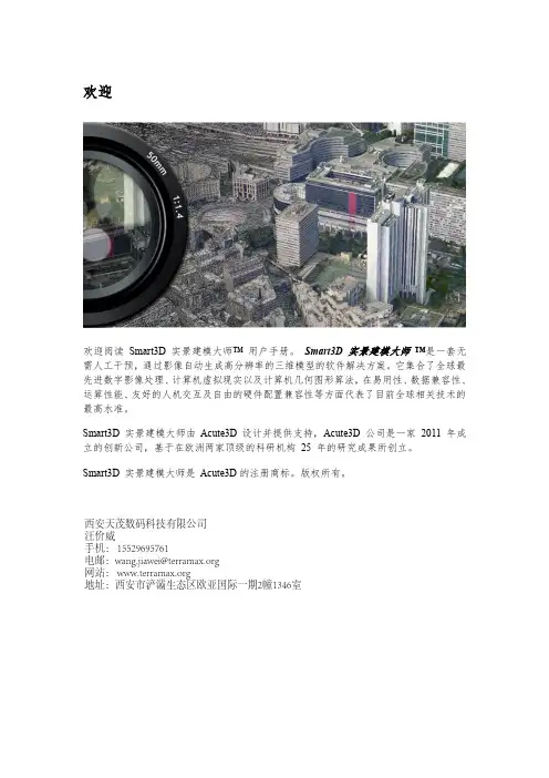
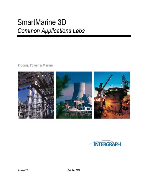
SmartPlant3D_SP3D软件基础操作SmartMarine 3DCommon Applications LabsVersion 7.3October 2007CopyrightCopyright ? 2007 Intergraph Corporation. All Rights Reserved. Including software, file formats, and audiovisual displays; may be used pursuant to applicable software license agreement; contains confidential and proprietary information of Intergraph and/or third parties which is protected by copyright law, trade secret law, and international treaty, and may not be provided or otherwise made available without proper authorization.Restricted Rights LegendUse, duplication, or disclosure by the Government is subject to restrictions as set forth in subparagraph (c) of the Contractor Rights in Technical Data clause at DFARS 252.227-7013, subparagraph (b) of the Rights in Computer Software or Computer Software Documentation clause at DFARS 252.227-7014, subparagraphs (b)(1) and (2) of the License clause at DFARS 252.227-7015, or subparagraphs (c) (1) and (2) of Commercial Computer Software--Restricted Rights at 48 CFR 52.227-19, as applicable. Unpublished---rights reserved under the copyright laws of the United States. Intergraph Corporation Huntsville, Alabama 35894-0001Warranties and LiabilitiesAll warranties given by Intergraph Corporation aboutequipment or software are set forth in your purchase contract, and nothing stated in, or implied by, this document or its contents shall be considered or deemed a modification or amendment of such warranties. Intergraph believes the information in this publication is accurate as of its publication date. The information and the software discussed in this document are subject to change without notice and are subject to applicable technical product descriptions. Intergraph Corporation is not responsible for any error that may appear in this document. The software discussed in this document is furnished under a license and may be used or copied only in accordance with the terms of this license. No responsibility is assumed by Intergraph for the use or reliability of software on equipment that is not supplied by Intergraph or its affiliated companies. THE USER OF THE SOFTWARE IS EXPECTED TO MAKE THE FINAL EVALUATION AS TO THE USEFULNESS OF THE SOFTWARE IN HIS OWN ENVIRONMENT.TrademarksIntergraph, the Intergraph logo, SmartSketch, FrameWorks, SmartPlant, INtools, MARIAN, and PDS are registered trademarks of Intergraph Corporation. Microsoft and Windows are registered trademarks of Microsoft Corporation. MicroStation is a registered trademark of Bentley Systems, Inc. ISOGEN is a registered trademark of Alias Limited. Other brands and product names are trademarks of their respective owners.Table of ContentsTable of ContentsLAB-1: Session File, Tasks, View and Window Management.................................... 4 LAB-2A: Filter Management –System ....................................................................... 8 LAB-2B: Filter Management –Object type (15)LAB-2C: Filter Management –Volume Filter........................................................... 17 LAB-2D: Filter Management – Properties (Optional Lab) . (20)LAB-2E: Filter Management –Properties (Optional Lab) ........................................ 26 LAB-2F: Filter Management –Properties (Optional Lab)......................................... 31 LAB-2G: Filter Management – Properties (Optional Lab) . (34)LAB-3: Creating Surface Style Rule.......................................................................... 37 LAB-4: Work Break Down Structure ........................................................................ 40 LAB-5: Inserting Control Points ................................................................................42 LAB-6: Tool Tip Editing ( Optional lab)................................................................... 44 LAB-7: SQL Filter (This lab is for Advance users only). (47)SmartMarine 3D Common Applications Labs 3Common ApplicationsLAB-1: Session File, Tasks, View and Window Management ObjectiveAfter This Lab Students will be able to Create a session file, modify settings, setup views and move around in a model Lecture: Instructor Needs to explain session template, session file, tasks, options, views and view manipulations 1 2 Start SmartMarine 3D using Start –Programs –Intergraph SmartMarine 3D –SmartMarine 3D. From the New dialog box, select the Empty template and click OK3From the Tasks menu, select Configure Task List4 SmartMarine 3D Common Applications LabsCommon Applications4 5 6 7 8 9Select all tasks from the left side and click Add. Then click OK. Now select Common from the Tasks menu. From the Window menu, select New Window three times such that four windows are open. From the Window menu select Tile Horizontally. Activate GraphicView1 by clicking in its title bar. From the named views pulldown on the Common toolbar, select Front.10 Similarly set GraphicView2 to Top, GraphicView3 to Right and GraphicView4 to Isometric. 11 Select Tools , Options to bring up the Options dialog box. 12 On the units of measure tab, select ft-in for distance.SmartMarine 3D Common Applications Labs 5Common Applications13 On the SmartSketch tab, set the dwell time for stack = 0.1 Seconds 14 Select file, Save as and save the session file on your desktop For SmartMarine 3D Setup and Admin class: This session file can be saved as session template. To save this as template, Select File menu, Save As and save this session template in \ProductDir\CommonApp\SessionT emplates\General The location for the Session Templates can be changed using the Tools->Option dialog box. Open this dialog and select the File Locations Tab. You can change this location to a UNC path and store all your session templates there.6 SmartMarine 3D Common Applications LabsCommon Applications 15 Select File menu –> DefineWorkspace16 Select the available training Ship 17 Under filters, select more to open the Select Filter dialog 18 Expand the Ship Filters folder, Select all filter and Ok on the form19 Ok on the define Workspace Form and Fit all views 20 Practice Different View Manipulation CommandsSmartMarine 3D Common Applications Labs 7Common ApplicationsLAB-2A: Filter Management – SystemObjectiveAfter This Lab Students will be able to Create and or display different type of filters Lecture: Instructor Needs to explain filter creation, display, modify and selection. 1 Select File, Define Workspace2 3 4 5 6Select More… to open the Select Filter dialog Expand the Ship Filters folder, Select all filter and Ok on the form Ok on the define Workspace Form and Fit all views Select File, Define Workspace or CTRL W, select more… Select My Filters folder, Select the Simple Filter Icon to open The New Filter Properties dialog box.8 SmartMarine 3D Common Applications LabsCommon Applica tions 7 8 9 Name the filter “Unit 1” Select Area2 , Unit 1 on the System Tree to select objects Expand Coordinate Systems by clicking on the + sign. Note: Do NOT click the name ‘Coordinate System’10 Press and hold the Ctrl key on the keyboard and select Unit 1 CS. 11 Click OK to accept the filter definition.12 Select the filter “Unit 1” 13 Click OK to accept the selected filter 14 Click OK to bring all Unit1 objects into the workspace.SmartMarine 3D Common Applications Labs 9Common Applications 15 Your View should now resemble the following graphic.16 Select Define Workspace or CTRL W, select more (17)Select My Filters folder, Select the Simple Filter Icon to open The New Filter Properties dialog box. 18 Name the filter “Unit 2”. Select Unit 2 on the System Tree to select objects 19 Expand Coordinate Systems by clicking on the + sign. Note: Do NOT click the name ‘Coordinate System’ 20 Press and hold the Ctrl key on the keyboard and select Unit 2 CS. Click OK to accept the filter definition. 21 Select th e filter “Unit 2”. Click OK to accept the selected filter. 22 Select OK to bring all Unit 2 objects into the workspace10 SmartMarine 3D Common Applications LabsCommon Applications23 Create a new Simple Filter named Building 1, to include Building 1 and Building 1 CS.SmartMarine 3D Common Applications Labs 11Common Applications 24 Create a new Simple Filter named Amines Unit, to include Amines Unit and Amines Unit CS 25 Create a new Simple Filter named Unit 1 & Unit 2, to include Unit 1, Unit 2, Unit 1CS and Unit 2 CS12 SmartMarine 3D Common Applications LabsCommon Applications 26 Your view should resemble this27 Create a new Simple filter Building 1 & Unit 2, to include Building 1, Unit 2, Building 1 CS and Unit 2 CS28 Select Define Workspace and select Unit 1 to Display all objects in Unit 1SmartMarine 3D Common Applications Labs 13Common Applications14 SmartMarine 3D Common Applications LabsCommon ApplicationsLAB-2B: Filter Management – Object type(Delivered Filters – Selection only)After This Lab Students will be able to select objects using object type filters Lecture: Instructor Needs to explain selection of objects using different filters. Also explain/show delivered catalog filters 1 2 3 4 5 Display Unit 1 if not already displayed Select Tools, Select by Filter command to open the Select Filter dialog box. Under Catalog filters, expand Default Filters, SMARTMARINE 3D Object Filters, Object Types and select Structure(select structure filter not the folder) Click OK to select all Structural objects in Displayed filter Your View should now resemble the following graphic.6Select Tools, Hide7Your view should resemble thisSmartMarine 3D Common Applications Labs 15Common Applications8 9Select tools, show all Select T ools, Select by Filter command to open the Select Filter dialog box.10 Under Catalog filters, expand Default Filters, SmartMarine 3D Object Filters, Object Types and select Cableway(select Cableway filter not the folder) 11 Click OK to select all Cableway objects in Displayed filter 12 Select Format Styles, Under Surface Tab select Green Color and select Apply Button 13 System will change all Electrical Objects to Green Color. Note: To change the Cableway back to original color, select cableway objects using same filter, select format - Styles and Select Apply Style by Rule and apply16 SmartMarine 3D Common Applications LabsCommon ApplicationsLAB-2C: Filter Management – Volume FilterObjectiveAfter This Lab Students will be able to Create and/or display filters based on Volumes Lecture: Instructor Needs to explain Volume filter creation, display, modify and selection.1 2 3 4 5 6 7 8Select define WorkSpace and select more Select the My Filters folder Select the Simple Filter Icon to open The New Filter Properties d ialog box Name the filter “Volume Unit 1” Select Ship name on Systems Tab Open Names Space Tab. Open the Layout volume by Clicking on + sign Select Volume Unit 1 Open the Volume Tab, and select Volume Unit 1SmartMarine 3D Common Applications Labs 17Common Applications 9 Click OK10 Select Volume Unit 1 and OK 11 Ok on the define Workspace Form 12 Your view should resemble this13 System display Volume Unit 1, and all objects which are fully or partially inside the volume 14 To display objects only within the volume, select the volume and use clip by objects. Select the Volume(box) and do tools hide.18 SmartMarine 3D Common Applications LabsCommon Applications15 Select Tools->Show All to displays all objects again. Go to View->Clear Clipping to remove the clipped volume. 16 Create a new Filter name Volume Unit 2, to include Shipname from Systems tab, Volume unit 2 from Named space tab and Volume Unit 2 from Volume tab 17 Display Volume Unit 2. Now select the volume unit 2 from space tab on workspace explorer, and clip by object. Hide the Volume box.18. Select Tools->Show All to displays all objects again. Go to View->Clear Clipping to remove the clipped volume SmartMarine 3D Common Applications Labs 19。

3D建模软件的操作方法教程3D建模软件是一种用于创建、编辑和渲染三维模型的工具。
这些软件通常用于游戏开发、动画制作、工业设计等领域。
本教程将介绍一些常见的3D建模软件的操作方法,帮助读者快速上手和熟练掌握使用这些软件的基本技能。
首先,我将介绍几个常见的3D建模软件,它们分别是Autodesk Maya、Blender和SketchUp。
这些软件在3D建模领域具有广泛的应用,并且都有较为友好的用户界面和丰富的功能。
Autodesk Maya是一款功能强大的3D建模软件,适用于游戏开发、动画制作和特效设计等领域。
在使用Maya之前,首先需要了解软件的界面布局。
Maya的界面主要由视窗区域、菜单栏、工具栏、属性编辑器等组成。
在视窗区域,可以通过鼠标或快捷键进行视角的切换和对象的选择。
在菜单栏中,可以找到各种常用的功能和操作命令。
而工具栏则包含了创建、编辑、变换对象等工具。
属性编辑器则用于调整对象的属性和细节。
Blender是一款开源的3D建模软件,适用于各种领域的建模需求。
与Maya相比,Blender的界面可能需要一些时间来适应。
在Blender的界面中,主要包含了视窗区域、工具栏、属性编辑器以及时间线等。
视窗区域用于查看和编辑3D模型,工具栏则包含了各种模型创建与编辑的工具。
属性编辑器用于调整对象的材质、纹理和动画等属性,而时间线则用于控制动画的播放和编辑。
SketchUp是一款简单易用的3D建模软件,适用于建筑和室内设计等领域。
与前两款软件不同,SketchUp的界面更加简洁和直观。
软件界面主要由视窗区域、菜单栏、工具栏以及实体编辑器等组成。
通过视窗区域,用户可以创建、编辑和观察3D模型。
菜单栏包含了各种模型创建和编辑的功能,而工具栏则包含了常用的工具和操作命令。
实体编辑器则用于对模型的几何体进行编辑和属性调整。
无论是哪种3D建模软件,在进行建模之前,首先需要了解基本的操作方法。
首先是对象的创建和编辑。

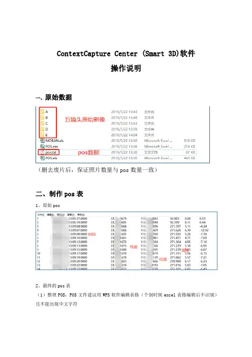
ContextCapture Center (Smart 3D)软件操作说明一、原始数据(删去废片后,保证照片数量与pos数量一致)二、制作pos表1、原始pos2、最终的pos表(1)整理POS:POS文件建议用WPS软件编辑表格(个别时候excel表格编辑后不识别)且不能出现中文字符(2)Photogroups 工作表中,name列需要与photos工作表的 PhotogroupName 一致,如下图所示:(3)5组镜头的经纬度一致,照片名与路径和照片组注意更改。
(4)照片后面的jpg大小写一定要和照片的jpg一样。
三、照片名称更改1、为方便后期操作,统一更改下照片名(1)多个架次可以按照A010001.jpg更改,A01代表第一架次,A02代表第二架次,以此类推。
(2)每改完一个文件夹中的照片后需要点击清除,之后选择下一个文件夹照片,全选再进行操作(注意照片顺序,极少数情况照片排到9999后从0001开始)(3)C组对应的是正视照片四、创建工程1、新建工程(工程不能出现中文路径)打开 Smart3D 软件,输入工程名称和存储路径,这里注意不要勾选创建空区块,因为我们需要直接导入表格来导入区块,示意图如下图所示:此时,导入上述的 Excel 表格(pos信息),如下图所示:关于影像组的基本信息如下图所示:照片组的每一张影像都可以预览到其图像且可以打开其路径检查相片数量和POS数量及曝光点(航路点)3D视图中显示曝光点(航路点)五、空三处理1、导入控制点2、控制点格式(点号 X6位 Y7位)如下图所示3、选择坐标系,如下图所示4、刺控制点(1)“3D试图”中鼠标悬停在控制点上方会出现控制点点号,框选控制点附近的黄色曝光点,记下照片名称(记下数字名称即可),接下来去“测量”中选区正射照片刺一下点(也就是C组对应的照片,按照之前记得数字名称),每个控制点每组镜头刺3~5张照片,这里第一步先刺正射镜头的,为了跑一边空三找“可能是视点”。


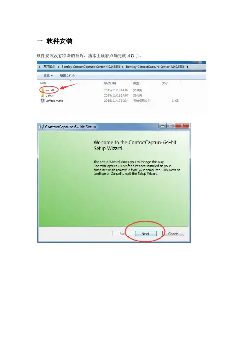
一软件安装软件安装没有特殊的技巧,基本上顺着点确定就可以了。
等待安装完成点击“Finish”之后软件会弹出一个配置框主要软件注册信息和系统配置信息等。
如果是破解版本的,基本上不用管直接点“OK”就可以了。
安装完成之后桌面上会出现三个图标第一个图标是主程序,第二个图标是软件的运行引擎,第三个图标是3D浏览功能图标(如果不是破解版,是需要有注册码支持的,不然软件是没法使用的)* 破解版安装演示的版本为Bentley ContextCapture Center 4.0.0.5556破解版,是支持破解的,破解文件在文件夹的patch文件夹下里面有两个文件第一步,需要复制Bentley.liclib.dll,然后进入到先前安装好的主程序的路径下粘贴复制的Bentley.liclib.dll,在弹出的对话框中选择“复制和替换”,直接替换安装路径下的文件第二步,双击Bentely_Licensing.reg文件,在弹出的注册表编辑器对话框中选择“是”,即可完成软件的破解。
二软件界面介绍1----代表新建一个工程2----代表打开一个已经存在的工程3----菜单栏界面比较简洁,基本上不用去进行复杂的操作,直接点击“新建工程”就可以开始进行操作了。
三简单案例实操下面我们用一组简单的数据来展示Smart3D是怎样进行处理的。
首先在主界面点击“新建工程”在弹出的对话框上,标识为1的位置输入想要新建的工程的名字(用英文和数字,不要使用特殊符合和中文,国外软件一般识别不了中文),标识为2的位置点击后面的“Browse”,选择工程存放的位置(不要选择中文路径,理由同上)。
设置好之后点击“OK”。
软件会进入到待处理界面在这个界面上突然间冒出很多标签,这些我们都不管,直接跳到添加照片的界面直接点击箭头所指的位置,就可以添加照片了全选所有的照片上面可以看到所添加的照片的信息,下面可以直接看到影像的具体参数(软件默认读取影像的EXIF信息)之后在返回“General”界面(主操作界面)软件会提示照片信息是不完整的,意思就是还没有做联合空三,接下来我们此时只需要点击“General”界面的提交联合空三按钮,软件会弹出一个空三设置对话框可以更改一个自己记得住的名字,也可以默认选择好坐标系统(如果人工添加过控制点),也可以用默认的影像独立坐标系统,之后是各种空三参数设置(一般默认就行),选择提交就行,这样软件就会开始准备跑空三。
Smart3D三维建模操作指南(无人机影像)Smart3D是一款强大的三维建模软件,它能够通过无人机影像数据生成高精度的三维模型。
本操作指南旨在帮助用户快速上手使用Smart3D进行三维建模。
步骤一:数据准备在开始三维建模之前,您需要准备无人机拍摄的影像数据。
确保数据完整并按序排列,同时保证数据质量较高,以获得更准确的建模结果。
步骤二:导入影像数据1. 在Smart3D软件打开界面中,点击“导入”按钮。
2. 在弹出的数据导入对话框中,选择您存储影像数据的文件夹。
3. 确认导入的数据类型为无人机影像,并点击“导入”按钮。
4. 等待软件自动导入影像数据。
步骤三:影像对齐1. 导入影像数据后,Smart3D将自动进行影像对齐。
您可以在软件界面中的“对齐”选项中查看对齐的结果。
2. 如果对齐结果不理想,您可以手动调整影像对齐。
选择“对齐”选项中的“手动调整”功能,并按照提示进行操作。
步骤四:建模参数设置1. 在影像对齐完成后,您可以进入建模界面,设置建模参数。
2. 根据建模需求,您可以调整建模精度、建模区域等参数。
确保参数设置合理,以获取符合要求的三维模型。
步骤五:开始建模1. 完成参数设置后,点击建模界面中的“开始建模”按钮。
2. Smart3D将根据您的参数设置,自动开始建模过程。
3. 建模过程可能需要一段时间,耐心等待建模完成。
步骤六:查看和导出建模结果1. 当建模完成后,您可以在Smart3D中查看生成的三维模型。
2. 您可以旋转、缩放和平移模型,以便更详细地观察它。
3. 如果满意建模结果,您可以选择导出模型。
在Smart3D界面中选择“导出”选项,选择导出格式和路径,最后点击“导出”按钮即可。
以上是Smart3D三维建模操作的基本步骤。
通过这些简单的步骤,您可以轻松地使用Smart3D进行无人机影像的三维建模。
祝您使用愉快!*注意:本操作指南仅作为参考,具体操作步骤可能因软件版本而略有不同。
请根据您所使用的软件版本进行操作。
3D3操作手册目录1.系统配置1.1 计算机配置1.2 相机配置1.3 投影仪配置2. 软件安装,注册激活及升级2.1 软件安装2.2 软件激活更新2.2.1 激活秘钥2.2.2 加密狗秘钥2.2.3 激活加密狗2.2.4 激活控软件狗3. 系统搭建3.1 3D扫描仪硬件搭建3.2 计算机设置4. 扫描仪标定4.1 创建/打开标定文件4.1.1 创建新的标定文件4.1.2 打开已有标定文件4.2 标定过程4.2.1 标定设置4.2.2 相机设置4.2.3 settings Calibration4.2.4 获取标定图像4.2.5 获得标定结果5. 获取扫描数据5.1 建立/打开新的工程5.2 转台设置5.3 数据扫描5.3.1 用转台扫描数据5.3.2 手动扫描6. 数据处理6.1 编辑网格6.2 网格操作6.3 数据拼接6.3.1 Alignment——对齐6.3.2 Combine——合并6.3.3 Uncombine——解除合并6.3.4 Finalizing Meshes6.4 数据的导入和导出6.4.1 数据导入6.4.2 数据导出第一章、系统配置3D3Solutions公司推出的FlexScan3D Scanner是一套集软硬件为一体的三维扫面仪,通过结构白光投影方式解析物体表面三维信息,Scanner由投影仪、相机、软件、以及一系列附件构成。
1.1计算机配置1.2相机配置(1)3D扫描仪入门级相机选型推荐方案(价格优先)·单相机扫描仪:PTGrey Chameleon CMLN-13S2M-CS·双相机扫描仪:IDS uEye UI-1545LE·镜头:Fujinon 12.5mm C-Mount Lens(2)3D扫描仪中级用户相机推荐方案(扫描速度优先,适用于扫描面部和人体特征)·130W双/多相机扫描仪:PTGrey FireWire Flea2 FL2G-13S2M or FL2-14S3M ·130W双/多相机扫描仪:IDS uEye GigE UI-5240CP·镜头:Fujinon 12.5mm C-Mount Lens(3)3D扫描仪逆向工程开发级相机推荐方案(精度、分辨率优先)·2M双相机扫描仪:PTGrey Grasshopper GRAS-20S4M-C·2M双相机扫描仪:Duo scanner setup: IDS uEye GigE UI-6250SE·镜头:5MP Fujinon 12.5mm C-Mount Lens1.3投影仪配置最低分辨率:800x600标准投影仪:1500+流明基于DLP(Digital Light Procession)技术LED投影仪:100+流明对比LED投影仪和普通正常投影仪:(1)LED投影仪优势:发热低;体积小巧;使用寿命长 (LED投影仪30,000小时,普通白光投影仪 3,000小时)(2)LED投影仪劣势分辨率、扫描精度、数据质量比较低;低光照,在复杂环境光影响下无法扫描;扫描黑色物体和高对比物体比较困难;选型局限性大。
ContextCapture Center (Smart 3D)软件操作说明一、原始数据(删去废片后,保证照片数量与pos数量一致)二、制作pos表1、原始pos2、最终的pos表(1)整理POS:POS文件建议用WPS软件编辑表格(个别时候excel表格编辑后不识别)且不能出现中文字符(2)Photogroups 工作表中,name列需要与photos工作表的 PhotogroupName 一致,如下图所示:(3)5组镜头的经纬度一致,照片名与路径和照片组注意更改。
(4)照片后面的jpg大小写一定要和照片的jpg一样。
三、照片名称更改1、为方便后期操作,统一更改下照片名(1)多个架次可以按照A010001.jpg更改,A01代表第一架次,A02代表第二架次,以此类推。
(2)每改完一个文件夹中的照片后需要点击清除,之后选择下一个文件夹照片,全选再进行操作(注意照片顺序,极少数情况照片排到9999后从0001开始)(3)C组对应的是正视照片四、创建工程1、新建工程(工程不能出现中文路径)打开 Smart3D 软件,输入工程名称和存储路径,这里注意不要勾选创建空区块,因为我们需要直接导入表格来导入区块,示意图如下图所示:此时,导入上述的 Excel 表格(pos信息),如下图所示:关于影像组的基本信息如下图所示:照片组的每一张影像都可以预览到其图像且可以打开其路径检查相片数量和POS数量及曝光点(航路点)3D视图中显示曝光点(航路点)五、空三处理1、导入控制点2、控制点格式(点号 X6位 Y7位)如下图所示3、选择坐标系,如下图所示4、刺控制点(1)“3D试图”中鼠标悬停在控制点上方会出现控制点点号,框选控制点附近的黄色曝光点,记下照片名称(记下数字名称即可),接下来去“测量”中选区正射照片刺一下点(也就是C组对应的照片,按照之前记得数字名称),每个控制点每组镜头刺3~5张照片,这里第一步先刺正射镜头的,为了跑一边空三找“可能是视点”。
SmartPlant3D结构专业操作⼿册1.1SmartPlant 3D结构专业⼊门⼿册(初版)主要⽬的:为结构专业建模⼈员提供⼊门帮助。
主要内容:⼀、初识SmartPlant 3D⼆、建⽴柱⽹三、建⽴模型四、绘制结构施⼯图如何使⽤:先阅读每节的简介,然后按照操作练习,完成上机操作,最后将会建⽴⼀框架的结构模型,⽣成⼀份图纸。
⼀、初识SmartPlant 3D1.SmartPlant 3D内容简介SmartPlant 3D(以下简称SP3D)是由intergraph公司开发的⼯⼚设计软件。
软件设置不同的Task,将⼯⼚设计中常⽤的专业进⾏分类,⽅便⽤户的使⽤。
软件中设置如下Task: Electrical, Common, Drawings and Reports, Equipment and Furnishings, Grids, Hangers and Supports, HVAC, Layout, Piping, Catalog, Space Management, Structural Analysis, Structure, Systems and Specifications.结构专业在使⽤时,经常⽤到的task有,Common, Drawings and Reports, Grids, Space Management, Structural Analysis, Structure。
其中Common 模块主要实现视图操作、定位、拷贝、粘贴等功能。
Common模块下的操作在其它模块下基本都可以实现。
Drawings and Reports模块能够实现出图和出报表,为满⾜不同公司的要求,图纸和报表⼀般需要定制。
本⼿册仅讲述如何在已经定制好的情况下,如何实现出图、报表⼯作。
Grids模块是柱⽹模块,⽤来定义结构柱⽹及标⾼。
Space Management是空间管理模块,定义Volume,实现出图。
导入数据:首先新建Block,可以在右侧选项中看到有两种加载影像数据的方式,分别为new block(新建区块),import block(导入区块),如下如右侧所示。
点击new block,可以创建一个空的区块。
在空区块中选择photos界面,分别可以选择Add photos和directory。
进行影像导入。
对于Add photos/Add Directories可以直接把影像全部导入,然后在导入的影像中,需要输入拍此相片相机的传感器横边尺寸(毫米)以及镜头焦距信息(毫米),在确认传感器尺寸与焦距信息完整正确填写以后,可以回到General界面;控制点影像关联对于具有像控点的航飞区域,需要在空三运算前将控制点与影像进行人工关联操作,该操作需要在Control points界面下完成。
关联操作如下:控制点编辑器界面添加控制点操作步骤:点击点击输入影像测量点,影像测量编辑器将被打开。
加,影像测量编辑器会同时关闭。
如果需要再输入一个测量点,需要重新点击开始。
在空三完成后,得到一个新区块,并且每张影像具有了精确的内外方为元素,点击提交Submit Reconstruction;在生成的Reconstruction中,点击Spatial framwork选项,可以在该选项下设置Bounding box来限定重建范围;Tiling选项下,将mode配置成Regular planar grid;同时,为Options配置合适的TileSize,用户可以根据软件下一行的建议值,设置Tile size,来确定合适的输出瓦片大小。
6提交成果产品在Reconstruction中的General界面下,点击Sumbit new production。
在Purpose选项中,确定输出的成果形式,如果输出三维模型,可以选择3D Mesh;在Format/Options选项下,选择相应的模型格式,然后保持其他选项默认;后续选项保持默认;点击Engine则任务开始计算。
Smart3d集群步骤
1、集群操作时,所有电脑必须在同一个局域网下。
2、将数据存放在一个盘里,比如说G盘,在G盘新建一个名为jobs的文件夹。
3、在主机上,打开Smart3d Capture Settings工具Configuration中的Job queue
directory路径改到G盘下的jobs。
4、在其他电脑上,找到主机电脑下的共享盘,并把此盘映射到网络位置,即在此电
脑上显示此网络盘,盘符名也必须是G盘。
5、建一个Smart3d工程,此工程也必须在G盘。
6、在建模时,打开主机和集群机上的引擎(橘红色工具),这样便实现了集群操作。
就是说一共有8台机器在运行,则会有8个建模tile同时处理。
Smart3DCapture软件快速上手操作指南Smart3D软件有几个主要的模块:包括Master、Setting、Engine、Viewer等。
• Master是一个非常友好的人机交互界面,相当于一个管理者,它创建任务,管理任务,监视任务的进度等;•
• Setting是一个中间媒介,它主要是帮助Engine指向任务的路径;
• Engine即是引擎端,只负责对所指向的Job Queue中的任务进行处理,可以独立于Master打开或者关闭;
• Viewer则可预览生成的三维场景和模型。
操作步骤如下:
1 新建工程:
首先要点击Start a new project创建一个New project并命名;
再为它选择一个project location,这样就在该路径下得到一个s3m格式的文件,并保存。
2 导入数据:
首先新建Block,可以在右侧选项中看到有两种加载影像数据的方式,分别为new block (新建区块),import block(导入区块),如下如右侧所示。
点击new block,可以创建一个空的区块。
在空区块中选择photos界面,分别可以选择Add photos和Add directory。
进行影像导入。
对于Add photos/Add Directories可以直接把影像全部导入,
然后在导入的影像中,需要输入拍此相片相机的传感器横边尺寸(毫米)以及镜头焦距信息(毫米),在确认传感器尺寸与焦距信息完整正确填写以后,可以回到General界面;
3 控制点影像关联
对于具有像控点的航飞区域,需要在空三运算前将控制点与影像进行人工关联操作,该操作需要在Control points界面下完成。
关联操作如下:
有效的控制点集合需要包含3个或以上的控制点,且每一控制点均具有2张及以上的影像刺点。
如下图所示,
控制点选项卡
控制点编辑器界面
添加控制点操作步骤:
1.选择空间坐标系
在坐标系框中选择控制点坐标系。
2.添加新的控制点
点击,在已选中的坐标系下创建一个新的控制点。
3. 输入控制点的空间坐标
在相应的列中输入控制点的坐标,注意每列对应的坐标轴和单位。
4. 输入影像测量点
点击输入影像测量点,影像测量编辑器将被打开。
在影像测量编辑器重,从左边影像列表中选中需要添加测量点的影像,找到找到控制点的位置,按住shift键+鼠标左键设定影像测量的位置。
点击确认完成对本影像的测量点的添加,影像测量编辑器会同时关闭。
如果需要再输入一个测量点,需要重新点击开始。
重复上述过程,可以增加任意多个影像测量点。
4 提交空三任务
在导入数据并设置完参数后(一般情况下采用默认设置即可),在General界面点击Submit Aerotriangulation,在保持每一步默认的提示下提交任务。
在等待空三任务完成后,可以进行重建操作。
5 提交重建任务
在空三完成后,得到一个新区块,并且每张影像具有了精确的内外方为元素,点击提交Submit Reconstruction;
在生成的Reconstruction中,点击Spatial framwork选项,可以在该选项下设置Bounding box来限定重建范围;
Tiling选项下,将mode配置成Regular planar grid;
同时,为Options配置合适的TileSize,用户可以根据软件下一行的建议值,设置Tile size,来确定合适的输出瓦片大小。
6 提交成果产品
在Reconstruction中的General界面下,点击Sumbit new production。
首先,确定产品输出名称
在Purpose选项中,确定输出的成果形式,如果输出三维模型,可以选择3D Mesh;
在Format/Options选项下,选择相应的模型格式,然后保持其他选项默认;
后续选项保持默认;
点击Engine则任务开始计算。