COP2000系列集成开发环境使用简介
- 格式:pdf
- 大小:1.03 MB
- 文档页数:10
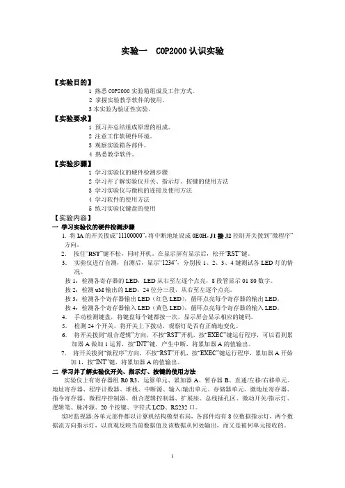
实验一 COP2000认识实验【实验目的】1 熟悉COP2000实验箱组成及工作方式。
2 掌握实验教学软件的使用。
3本实验为验证性实验。
【实验要求】1 预习并总结组成原理的组成。
2 注意工作软硬件环境。
3 观察实验箱各部件。
4 熟悉教学软件。
【实验步骤】1 学习实验仪的硬件检测步骤2 学习并了解实验仪开关、指示灯、按键的使用方法3 学习实验仪与微机的连接及使用方法4 学习软件的使用方法5 练习实验仪键盘的使用【实验内容】一学习实验仪的硬件检测步骤1. 将IA的开关拨成“11100000”,将中断地址设成0E0H,J1接J2控制开关拨到“微程序”方向。
2.按住“RST”键不松,同时开机。
在显示屏有显示后,松开“RST”键。
3.实验仪进行自测,自测后,显示“1234”,分别按1、2、3、4键测试各LED灯的情况。
按1:检测各寄存器的LED,LED从右至左逐个点亮,8段管显示01-80数字。
按2:检测uM输出的LED,24位分三段,从右至左逐个点亮。
按3:检测各个寄存器输出LED(红色LED),循环点亮每个寄存器的输出LED。
按4:检测各个寄存器输入LED(黄色LED),循环点亮每个寄存器的输入LED。
4.手动检测键盘,将键盘每个键都按一次,显示屏会显示相应的键码。
5.检测24个开关,将开关上下拨动,观察灯是否有正确地变化。
6.将开关拨到“组合逻辑”方向,不按“RST”开机,按“EXEC”键运行程序,可以看到累加器A做加1运算,按“INT”键,产生中断,将累加器A的值输出。
7.将开关拨到“微程序”方向,不按“RST”开机,按“EXEC”键运行程序,累加器A开始加1,按“INT”键,将累加器A的值输出。
二学习并了解实验仪开关、指示灯、按键的使用方法实验仪上有寄存器组R0-R3、运算单元、累加器A、暂存器B、直通/左移/右移单元、地址寄存器、程序计数器、堆栈、中断源、输入/输出单元、存储器单元、微地址寄存器、指令寄存器、微程序控制器、组合逻辑控制器、扩展座、总线插孔区、微动开关/指示灯、逻辑笔、脉冲源、20个按键、字符式LCD、RS232口。
imagine making theimpossible possible2000Series controllersBuilt on our experience of design and applications knowledge spanning more than 40 years, the Eurotherm®2000 series brings you performance you can rely on and accuracy you can trust.At the same time no other range of controllers makes operation so easy. Menu driven operation provides easy intuitive and consistent access to all the controller functions.Simply imagine process excellence…and with Eurotherm you will achieve it. Our ranges of controllers provide world class control and versatility with clear, user friendly, operator interfaces. Add to this, a strong sales team of qualified engineers who understand your process, an absolute commitment to innovation by continuously re-investing in research and development; we can and do imagine making the impossible possible for our customers.Internal timer– A 5 mode timer suitable for simple time based profiling applications Universal input–9 different thermocouples, PT100, DC linear and a downloadable customcurveFour outputs–up to 4 outputs including 2 modular with many options including DCoutputsCommunication protocols–Modbus RTU, EI-Bisynch, DeviceNet®Three internal alarms–Configurable as High, Low, Deviation and Deviation High or Low alarms Two outputs– 1 relay and 1 logic (can be used as a relay with an external module)Suitable for•Small ovens •Chillers •Sterilisers •Trace heating •Heat sealing •Dwell timer–simple ramp dwell profile applicationsFour internal alarms–configurable as High, Low, Deviation,Deviation High, Deviation Low, Highand Low current alarmsSuitable for•Cold stores •Ovens and furnaces •Plastic extrusion •Packaging machines •Food and brewing applications •Every 2000 Series controller can be tailored to provide thecontrol solution you need. Modular design and easy, on-site configuration matches application requirements andgives you a temperature and process control solution that’sready to run the first time you switch it on.The 2000 Series provides control strategies ranging fromsimple ON/OFF to PID with advanced overshoot protection, providing the best control for the widest range of applications including valve positioning. Within the 2000Series there is also the 2500 Modular Controller and the 2604/2704 Controllers which, with their enhanced functionality and multiloop capability, offer a powerful addition to the range. Please consult Eurotherm sales for more information on these products.requirements Programming –up to 20, 16 segment programs (4 in the 2416) are available with 8 digital event outputs Four internal alarms –configurable as High, Low, Deviation,Deviation High or Low, high and Low Current alarms high and low output,high and low input 2, High and low setpoint and one Rate of change alarmModular –up to 4 outputs of which 3 aremodular with many different optionswithin the different modulesModules –up to 16 different types of moduleare availableCommunication protocols –Modbus RTU, EI-Bisynch, DeviceNet,Profibus DP Suitable for •Single and multi-zone furnaces •Kilns •Environmental chambers •Simple ratio •Humidity •Chemical and pharmaceutical •Applications •Glass furnaces and lehrs •Set p o in t FFOP Flow Meter FTAT Analytical Sensor PID Loo pPV +2400Dosing Pump Setpoint Easy to use controllers for greater flexibilityT im e Te mp e ra t ur e Setpoint Dwell time Switch off Ramp controlDwell Timer FunctionalityTe mp e ra t ur eEnd Type = DwellT im e End Type = Off Holdback atstart of dwellMaster ProgrammerSlave ControllersPDS communications M P gSC mmunic c ations PDS com In 2000 Series controllers it is possible to use the PDS communication link tosend a setpoint from one controller to a network of slave devices - providingthe economical creation of multi-zone temperature control solutions.PDS setpoint retransmissionRatiometric PyrometerThermocouple Output Switchover between two points 4-20mAmocouple Master Output Slave PDS Retransmission with FeedforwardModbus RTU Modbus Master The 2000 Series uses industry standard protocols such as Modbus RTU, DeviceNet or Profibus DPto communicate with supervisory systems andPLCs over EIA232, EIA485 (2 wire) or EIA422 (4wire). This carries the information and overallcontrol into the supervisory system whilemaintaining local access to the local equipmentensuring overall plant integrity in all situations.CommunicationSometimes it is desirable to control a process using two separate inputs toderive the PV (process value). This could be based on a highest wins, lowestwins, some function of the two inputs, or switching between the two inputs atsome pre-determined point in the process.For example, an application could consist of a thermocouple for measuring upto 800°C and a Ratiometric Pyrometer for measuring the range between700°C and 1,400°C.Typically when the temperature is below 740°C the thermocouple providesthe PV and, when between 740°C and 780°C the controller switches gentlyfrom the thermocouple to the Pyrometer which provides the PV up to 1,400°C.Derived inputsUsing Eurotherm setpoint retransmission over PDScommunications it is possible to use two 2400 controllersas a cascade control system with the output of the first (ormaster controller) forming the setpoint of the second (orslave controller).Eurotherm advanced algorithms enable the use of eithersetpoint or PV feedforward to limit the slave setpoint - forexample ±10% of the master setpoint or PV.Cascade control iTools configuration software enables you to store and clone controller configurations, as well as commission your process control system. This facility significantly reduces installation and commissioning time while commissioning timeEurotherm flexible 2000 Series offers a truly versatilesolution to all your requirements.Selection guide Features Panel size (DIN)IP Rating Single LoopDisplay TypeSupply Voltage Input Type PV Accuracy Control Types SP ProgrammerAnalogue IP/OP Digital IP/OPDigital Comms Alarm TypesPC Configuration21161/321/16IP6521002216e 2208e 1/16DIN rail 1/8IP6522002204e 1/4TC, RTD, mV, mA, V 1 x 4 dig LED TC, RTD, mV, mA, Volts 2 x 4 dig LED <0.25%On/Off. PID none In: 1 Out: 0In: 1 Out: 2none none none none none none none none none none none none none List based <0.25%On/Off. PID, VP none none none In: 1 Out: 1In: 3 Out: 4Modbus, DeviceNet List based 24V dc/ac 85-264V ac 85-264V ac 2132Dual input control Hi, Lo, Dev,Sensor break,Event, Heater failHi, Lo, Dev, Sensor break, Event, Heater fail Hi, Lo, Dev, Sensor break, 2416240824041/161/81/4IP652400TC, RTD, mV,mA, Volts 2 x 4 dig LED <0.2%On/Off. PID, VP 20 x 16 segments In: 2 Out: 3In: 11 Out: 11List based 24V dc/ac 85-264V ac Modbus, DeviceNet, Profibus Special FeaturesMaths EquationCombinational LogicTimers/Counters/TotalsReal Time Clock© Copyright Eurotherm Limited 2011Invensys, Eurotherm, the Eurotherm logo, Chessell, EurothermSuite, M ini8, Eycon, Eyris, EPower, nanodac and Wonderware are trademarks ofInvensys plc, its subsidiaries and affiliates. All other brands may be trademarks of their respective owners.All rights are strictly reserved. No part of this document may be reproduced, modified, or transmitted in any form by any means, nor may it be stored in a retrieval system other than for the purpose to act as an aid in operating the equipment to which the document relates, withoutthe prior written permission of Eurotherm limited.Eurotherm Limited pursues a policy of continuous development and product improvement. The specifications in this documentmay therefore be changed without notice. The information in this document is given in good faith, but is intended for guidance only.Eurotherm Limited will accept no responsibility for any losses arising from errors in this document.Bermuda Bolivia Bosnia and Herzegovina Botswana Brazil Brunei Darussalam Bulgaria Cambodia Cameroon Canada Central African Republic Chad Chile Colombia Congo Costa Rica Côte d’Ivoire Croatia Cyprus Czech Republic Denmark Djibouti Ecuador Egypt El Salvador Eritrea Estonia Ethiopia Fiji Finland Georgia Ghana Greece Greenland Guinea Hungary Iceland Indonesia Iraq Israel Jamaica Japan Jordan Kazakhstan Kenya Kuwait Kyrgyzstan Laos MozambiqueMyanmarNamibiaNicaraguaNigerNigeriaNorwayOmanPakistanPalestinian TerritoryPapua New GuineaParaguayPeruPhilippinesPolandQatarRomaniaRussiaRwandaSaudi Arabia Senegal Serbia and Montenegro Sierra LeoneSingapore Slovakia Slovenia Somalia South AfricaSri Lanka SudanSwaziland SyriaTajikistanTanzania Thailand The GambiaTunisia TurkeyTurkmenistanUganda Ukraine United Arab Emirates Uruguay UzbekistanVenezuelaVietnam Yemen Zambia ZimbabweAUSTRALIA Melbourne Invensys Process Systems Australia Pty. Ltd.T (+61 0) 8562 9800F (+61 0) 8562 9801E info.*************************AUSTRIA Vienna Eurotherm GmbH T (+43 1) 7987601F (+43 1) 7987605E info.*************************BELGIUM & LUXEMBOURG Moha Eurotherm S.A/N.V.T (+32) 85 274080F (+32) 85 274081E info.*************************BRAZIL Campinas-SP Eurotherm Ltda.T (+5519) 3707 5333F (+5519) 3707 5345E ******************************CHINA Eurotherm China T (+86 21) 61451188F (+86 21) 61452602E info.*************************Beijing Office T (+86 10) 5909 5700F (+86 10) 5909 5709/5909 5710E info.*************************FRANCE Lyon Eurotherm Automation SA T (+33 478) 664500F (+33 478) 352490E ******************************GERMANY Limburg Eurotherm Deutschland GmbH T (+49 6431) 2980F (+49 6431) 298119E info.*************************INDIA Mumbai Invensys India Pvt. Ltd.T (+91 22) 67579800F (+91 22) 67579999E info.*************************IRELAND Dublin Eurotherm Ireland Limited T (+353 1) 4691800F (+353 1) 4691300E info.*************************ITALY Como Eurotherm S.r.l T (+39 031) 975111F (+39 031) 977512E info.*************************KOREA Seoul Invensys Operations Management Korea T (+82 2) 2090 0900F (+82 2) 2090 0800E info.*************************NETHERLANDS Alphen a/d Rijn Eurotherm B.V.T (+31 172) 411752F (+31 172) 417260E ******************************POLAND Katowice Invensys Eurotherm Sp z o.o.T(+48 32) 7839500F (+48 32) 7843608/7843609E info.*************************SPAIN MadridEurotherm España SA T(+34 91) 6616001F (+34 91) 6619093E info.*************************SWEDEN MalmoEurotherm AB T(+46 40) 384500F (+46 40) 384545E ******************************SWITZERLAND Wollerau Eurotherm Produkte (Schweiz) AG T (+41 44) 7871040F (+41 44) 7871044E info.*************************UNITED KINGDOM Worthing Eurotherm Limited T (+44 1903) 268500F (+44 1903) 265982E info.*************************U.S.A.Ashburn VA Eurotherm Inc.T (+1 703) 724 7300F (+1 703) 724 7301E info.*************************ED63。
第一章性能特点COP2000计算机组成原理实验系统主要是为配合讲授与学习《计算机组成原理》课程而研制的。
与其它产品相比,具有以下特点:1.1 硬件先进特点1.实时监视器各单元部件都以计算机结构模型布局,清晰明了,各寄存器、部件均有8位数据指示灯显示其二进制值,两个8段码LED显示其十六进制值,清楚明了,两个数据流方向指示灯,以直观反映当前数据值及该数据从何处输出,而又是被何单元接收的。
这是该产品独创的“实时监视器”,使得系统在实验时即使不借助PC机,也可实时监控数据流状态及正确与否,彻底改变了其它实验设备为监控状态必须加入读操作的不真实实验方法,使得学生十分容易认识和理解计算机组成结构。
实验系统各部件可以通过J1、J2、J3座之间不同的连线组合,可进行各部件独立的实验,也可进行各部件组合实验,再通过与控制线的组合,就可构造出不同结构及复杂程度的原理性计算机。
2.开放式设计实验系统的软硬件对用户的实验设计具有完全的开放特性。
与众不同的是:COP2000各实验模块的数据线、地址线与系统之间的挂接是通过三态门,而不是其它实验设备所采用的扁平连线方法,而数据线、地址线是否要与系统连通,则由用户连线控制,这样,就真实的再现了计算机工作步骤。
需要强调指出的是:用“连线跨接”并不能说明其开放特性,而所谓的开放性应指的是运算器、控制器及微程序指定的格式及定义能否进行修改和重新设计。
COP2000系统的运算器采用了代表现代科技的EDA技术设计,随机出厂时,已提供一套已装载的方案,能进行加、减、与、或、带进位加、带进位减、取反、直通八种运算方式,若用户不满意该套方案,也可自行重新设计并通过JTAG口下载。
控制器微指定格式及定义可通过键盘和PC机进行重新设计,从而产生与众不同的指令系统。
系统的数据线、地址线、控制线均在总线插孔区引出,并设计了40芯锁进插座,供用户进行RAM、8251、8255、8253、8259等接口器件的扩展实验。
实验一COP2000认识实验报告摘要:一、引言COP2000是一款基于Windows操作系统的计算机模拟软件,可以用于学习计算机的组织结构和编程语言。
本实验主要通过使用COP2000软件,加深对计算机组织和编程的认识。
二、实验目的1.了解计算机的组成结构和基本原理;2.熟悉使用COP2000软件模拟计算机的组织结构;3.掌握汇编语言基本指令的使用;4.理解汇编指令的执行过程和寄存器的作用。
三、实验内容与方法1.实验环境:COP2000软件;2.实验步骤:(1)打开COP2000软件并创建一个新的项目;(3)编译并运行程序,观察指令的执行过程和结果;(4)通过查阅资料,了解各个指令的功能和寄存器的作用。
四、实验结果与分析我编写了如下的一段简单的汇编语言程序:```MOVAL,10;将10赋值给AL寄存器ADDAL,5;将AL寄存器的值与5相加MOVAH,AL;将AL寄存器的值复制给AH寄存器```在运行程序之后,我发现这段程序的执行结果如下:```AL=10AL=15AH=15```通过观察程序的执行结果,我得出了以下的结论:1.MOV指令用于将一个值赋给特定的寄存器,类似于变量赋值操作;2.ADD指令用于将指定的寄存器中保存的值与给定的操作数相加,并将结果保存到该寄存器中;3.汇编指令的执行顺序是按照程序的顺序依次执行的;4.寄存器的作用是用于暂存和传输数据,不同寄存器有不同的用途,在程序中可以根据需要选择合适的寄存器。
五、实验总结与体会通过本次实验,我对计算机的组织结构和编程语言有了更深入的了解。
我学会了使用COP2000软件模拟计算机的组织结构,并编写了一段简单的汇编语言程序。
通过观察程序的执行过程和结果,我对汇编指令的使用方法和寄存器的作用有了更清楚的认识。
然而,在实验过程中,我也遇到了一些困难。
首先,对于汇编语言的语法和指令集不够熟悉,导致在编写程序时出现了一些错误。
其次,我对一些指令的作用和寄存器的使用方法有一些疑惑,需要查阅资料进行了解和学习。
实验一 COP2000认识实验【实验目的】1 熟悉COP2000实验箱组成及工作方式。
2 掌握实验教学软件的使用。
【实验要求】1 预习并总结组成原理的组成。
2 注意工作软硬件环境。
3 观察实验箱各部件。
4 熟悉教学软件。
【实验步骤】1 学习实验仪的硬件检测步骤2 学习并了解实验仪开关、指示灯、按键的使用方法3 学习实验仪与微机的连接及使用方法4 学习软件的使用方法5 练习实验仪键盘的使用【实验内容】一学习实验仪的硬件检测步骤1. 将IA的开关拨成“11100000”,将中断地址设成0E0H,J1接J2控制开关拨到“微程序”方向。
2.按住“RST”键不松,同时开机。
在显示屏有显示后,松开“RST”键。
3.实验仪进行自测,自测后,显示“1234”,分别按1、2、3、4键测试各LED灯的情况。
按1:检测各寄存器的LED,LED从右至左逐个点亮,8段管显示01-80数字。
按2:检测uM输出的LED,24位分三段,从右至左逐个点亮。
按3:检测各个寄存器输出LED(红色LED),循环点亮每个寄存器的输出LED。
按4:检测各个寄存器输入LED(黄色LED),循环点亮每个寄存器的输入LED。
4.手动检测键盘,将键盘每个键都按一次,显示屏会显示相应的键码。
5.检测24个开关,将开关上下拨动,观察灯是否有正确地变化。
6.将开关拨到“组合逻辑”方向,不按“RST”开机,按“EXEC”键运行程序,可以看到累加器A做加1运算,按“INT”键,产生中断,将累加器A的值输出。
7.将开关拨到“微程序”方向,不按“RST”开机,按“EXEC”键运行程序,累加器A开始加1,按“INT”键,将累加器A的值输出。
二学习并了解实验仪开关、指示灯、按键的使用方法实验仪上有寄存器组R0-R3、运算单元、累加器A、暂存器B、直通/左移/右移单元、地址寄存器、程序计数器、堆栈、中断源、输入/输出单元、存储器单元、微地址寄存器、指令寄存器、微程序控制器、组合逻辑控制器、扩展座、总线插孔区、微动开关/指示灯、逻辑笔、脉冲源、20个按键、字符式LCD、RS232口。

柜面操作平台COP应用手册编写人: 刘世昌编写日期: 2002年7月目录第一章COP平台介绍 (4)1.1概述 (4)1.2COP平台的特点 (4)1.3平台体系结构 (6)1.4COP平台工作原理 (7)1.5COP平台各部分功能 (9)预编译程序 (9)核心处理程序 (9)流程控制与运算模块 (10)窗体运行模块 (10)数据库服务模块 (11)用户自定义模块 (11)设备驱动程序 (11)第二章COP平台配置 (12)2.1COP平台结构 (12)COP平台结构图 (12)COP的平台环境变量 (12)2.2COP组件说明 (13)bin/ 子目录下的可执行文件 (13)device/ 子目录下存放的各种外设驱动命令码和字库. (13)dllib/ 子目录下存放的设备动态库文件 (14)config/ 子目录下存放的配置文件 (14)data/ 子目录存放资源定义和应用程序。
(14)data/function/ 前台应用程序存放路径 (14)data/resource/ 前台资源文件存放路径 (15)2.3COP配置文件说明 (15)系统参数的配置 (15)copsys.cfg的使用及配置方法 (15)comm.cfg的使用及配置方法 (16)host_addr.cfg的使用及配置方法 (16)通讯头配置文件使用及配置方法 (16)copterm终端模式配置 (17)map文件配置 (18)tft.conf传输文件文件配置 (19)2.4COP平台命令 (19)commsvr (19)copc、nn (20)cop 20devload (20)tftserver (21)init_encrypt (21)2.5利用COP解释执行一个小程序 (22)第三章交易编制说明 (23)3.1交易编制基本步骤 (23)3.2交易模板及交易驱动器 (23)交易模板 (23)交易头文件head.h (25)交易驱动器 (31)3.3前端新增交易步骤 (44)3.4特殊交易的实现 (47)第四章COP开发环境 (50)4.1COP目录环境 (50)4.2环境变量 (51)4.3COP命名规则 (53)窗口命名规则 (53)窗口处理程序命名规则 (53)数据域命名规则 (53)数据域处理程序命名规则 (53)表格命名规则 (54)表格处理程序命名规则 (54)菜单命名规则 (54)菜单过程命名规则 (55)列表命名规则 (55)交易处理程序命名规则 (55)键盘事件命名规则 (55)输出对象命名规则 (56)系统程序命名规则 (56)公共程序命名规则 (56)4.4COP程序编写规范 (56)程序规格书 (56)修改说明 (57)操作前端数据库 (57)程序编写风格 (57)4.5COP程序的编写 (58)交易前处理的编写 (58)交易提交前处理的编写 (58)数据域前处理的编写 (59)数据域后处理的编写 (60)窗口前处理的编写 (60)对象处理的编写 (61)公共程序编写 (62)交易调度程序编写 (64)第五章COP平台工具 (65)5.1COP平台工具环境 (65)5.2TOOLS.CFG的使用及配置方法 (65)5.3集成开发工具COPTOOLS (65)5.4平台其他工具 (66)广播工具 (66)版本更新工具 (66)屏幕调整工具 (67)传输文件工具 (67)第一章 COP平台介绍1.1 概述COP 平台UNIX版本是一种金融业务系统客户端开发和运行平台。
cop2000机组课程设计一、课程目标知识目标:1. 学生能够掌握cop2000机组的基本结构及其工作原理,了解其主要部件的功能和相互关系。
2. 学生能够理解cop2000机组的性能参数,如功率、效率、耗油量等,并学会分析这些参数对实际运行的影响。
3. 学生能够掌握cop2000机组的操作流程和安全规范,了解机组维护保养的基本知识。
技能目标:1. 学生能够独立进行cop2000机组的操作,包括启动、运行、停机等环节,并具备处理一般故障的能力。
2. 学生能够运用所学知识对cop2000机组进行性能分析,提出优化运行的建议。
3. 学生能够通过实际操作,掌握机组维护保养的基本技能,提高实际动手能力。
情感态度价值观目标:1. 学生通过学习cop2000机组课程,培养对能源设备行业的兴趣和热爱,增强职业责任感。
2. 学生能够树立安全意识,养成严谨、规范的操作习惯,提高团队合作能力。
3. 学生能够关注环保问题,认识到节能降耗的重要性,形成绿色环保的观念。
课程性质:本课程为专业课,旨在帮助学生掌握cop2000机组的相关知识和技能,培养实际操作能力。
学生特点:学生具备一定的理论基础,对实际操作有较高的兴趣,但动手能力有待提高。
教学要求:注重理论与实践相结合,强化实际操作训练,提高学生的知识运用能力和实践技能。
同时,关注学生的情感态度价值观的培养,使他们在掌握专业知识的同时,形成良好的职业素养。
通过分解课程目标为具体的学习成果,为后续的教学设计和评估提供依据。
二、教学内容本章节教学内容将围绕cop2000机组的基本原理、操作流程、维护保养及性能分析等方面展开。
1. 基本原理:- 介绍cop2000机组的基本结构,包括发动机、发电机、控制系统等主要部件及其功能;- 深入解析cop2000机组的工作原理,探讨各部件间的协同工作方式。
2. 操作流程:- 按照教材相关章节,详细讲解cop2000机组的启动、运行、停机等操作流程;- 强调操作过程中的安全规范,介绍应对突发状况的处理方法。
实验一 COP2000认识实验【实验目的】1 熟悉COP2000实验箱组成及工作方式。
2 掌握实验教学软件的使用。
3本实验为验证性实验。
【实验要求】1 预习并总结组成原理的组成。
2 注意工作软硬件环境。
3 观察实验箱各部件。
4 熟悉教学软件。
【实验步骤】1 学习实验仪的硬件检测步骤2 学习并了解实验仪开关、指示灯、按键的使用方法3 学习实验仪与微机的连接及使用方法4 学习软件的使用方法5 练习实验仪键盘的使用【实验内容】一学习实验仪的硬件检测步骤1. 将IA的开关拨成“11100000”,将中断地址设成0E0H,J1接J2控制开关拨到“微程序”方向。
2.按住“RST”键不松,同时开机。
在显示屏有显示后,松开“RST”键。
3.实验仪进行自测,自测后,显示“1234”,分别按1、2、3、4键测试各LED灯的情况。
按1:检测各寄存器的LED,LED从右至左逐个点亮,8段管显示01-80数字。
按2:检测uM输出的LED,24位分三段,从右至左逐个点亮。
按3:检测各个寄存器输出LED(红色LED),循环点亮每个寄存器的输出LED。
按4:检测各个寄存器输入LED(黄色LED),循环点亮每个寄存器的输入LED。
4.手动检测键盘,将键盘每个键都按一次,显示屏会显示相应的键码。
5.检测24个开关,将开关上下拨动,观察灯是否有正确地变化。
6.将开关拨到“组合逻辑”方向,不按“RST”开机,按“EXEC”键运行程序,可以看到累加器A做加1运算,按“INT”键,产生中断,将累加器A的值输出。
7.将开关拨到“微程序”方向,不按“RST”开机,按“EXEC”键运行程序,累加器A开始加1,按“INT”键,将累加器A的值输出。
二学习并了解实验仪开关、指示灯、按键的使用方法实验仪上有寄存器组R0-R3、运算单元、累加器A、暂存器B、直通/左移/右移单元、地址寄存器、程序计数器、堆栈、中断源、输入/输出单元、存储器单元、微地址寄存器、指令寄存器、微程序控制器、组合逻辑控制器、扩展座、总线插孔区、微动开关/指示灯、逻辑笔、脉冲源、20个按键、字符式LCD、RS232口。
目录一、总体介绍............................................................................................. (1)1.1 概述............................................................................................. (1)1.2 特点............................................................................................. (1)1.3 功能............................................................................................. (2)二、技术指标............................................................................................. (3)三、工作原理............................................................................................. (7)① 主机电路............................................................................................. (7)② 内线电路............................................................................................. (7)③ 中继电路............................................................................................. (8)四、结构与安装............................................................................................. (9)4.1 内部结构............................................................................................. (9)4.2 外围设备............................................................................................. (15)4.3 安装环境............................................................................................. (15)4.4 整机检查与测试 (15)4.5 设置须知............................................................................................. (17)4.6 蓄电池的连接............................................................................................. (18)4.7 地线要求............................................................................................. (19)五、交换机音源及语音............................................................................................. (20)5.1 信号音与音乐............................................................................................. (20)5.2 交换机语音............................................................................................. (21)六、话务处理............................................................................................. (25)6.1 话务处理状态............................................................................................. (25)6.2 值班总机话务功能 (26)6.2.1 总机夜服转移 (26)6.2.2 总机功能锁设置 (27)6.2.3 总机互答 (27)6.2.13 总机插入通话 (28)6.2.14 总机强插通话 (29)6.2.15 总机直接插入分机 (29)6.2.16 转接暂停 (29)七、参数设置............................................................................................. (30)7.1 系统参数............................................................................................. . (30)7.1.2 时间............................................................................................. (30)7.1.3 复位............................................................................................. (31)7.1.4 主板/备板切换 (31)7.1.5 故障诊断与检测 (32)7.2 FLASH(闪存)主机板 (33)7.2.1 FLASH 主机板说明 (33)7.2.2 升级方法 (34)①传送程序数据 (34)②写入或复制数据 (34)③工作程序切换 (35)7.3 分机的号码与级别设置 (35)7.3.1 分机的起点与终点 (35)7.3.2 分机号码 (36)7.3.3 分机级别 (38)7.4 呼叫路由............................................................................................. . (40)7.4.1 出局局号 (40)7.4.2 专向局............................................................................................. (41)7.4.3 等位局............................................................................................. (42)7.4.4 特定市话 (43)7.5 与呼叫有关的参数和开关 (44)7.5.1 缩位拨号(被叫号码替换) (44)7.5.2 分机间禁呼(限呼) (45)7.5.3 分机呼入管制 (45)7.5.4 分机停机 (45)7.5.5 分机来话提示音 (45)7.5.6 分机来话转移 (46)7.5.7 入局呼叫分机转移 (46)7.5.8 分机脉冲发号 (47)7.5.9 外线呼入限制 (47)7.5.10 郊县字头 (47)7.5.11 限制呼叫的电话号码 (48)7.5.12 只能够呼叫的外线电话号码 (48)7.5.13 分机只使用帐卡号码 (49)7.5.14 外线呼入方式 (49)7.5.15 外线密码锁 (49)7.5.16 外线入群呼分机方式 (50)7.6 主要功能参数与设置 (51)7.6.1 分机密码漫游 (51)7.6.2 来电显示 (51)7.6.3 经理/秘书 (52)7.6.4 热线........................................................................................ .. (52)7.6.5 叫醒服务(闹钟) (53)7.6.6 通话限时 (54)7.6.7 电话会议 (54)7.6.8 内外线分组(群)设置 (56)7.6.9 环路外线入局连选设置 (57)7.6.10 帐号计费 (58)7.6.11 IP 电话方式出局 (59)7.6.12 中继汇接 (61)7.6.13 报警(接警)系统 (63)7.6.14 留言........................................................................................ (65)7.6.15 指定录音 (67)7.6.16 分机出局发主叫号码方式 (68)7.6.17 分机‘自限方式’ (68)7.6.18 非本地手机号码前加发‘0’ (69)7.6.19 短号码内线或出局呼叫功能 (70)7.6.20 非 0 加号 (70)7.6.21 被叫全加发号 (70)7.6.22 来电代接 (71)7.7 外线基本参数........................................................................................ . (71)①间局/直局........................................................................................ . (71)②中继出局循环 (71)③外线可调参数设置 (72)④外线开关........................................................................................ (72)⑤外线发号方式 (73)7.8 其它参数........................................................................................ (73)①听数字语音时长 (73)②交换机总机部数 (73)③双音频接收器退出时长 (73)④内线呼叫时长 (73)⑤呼入拆线忙音时长 (73)⑥完号时长............................................................................................. . (74)7.9 其它功能............................................................................................. . (74)①转接(转移)总机设置权 (74)②分机转接功能 (74)③总机转接拍叉与不要拍叉 (74)④分机用户接口出局呼叫提示音 (74)⑤内外振铃区分 (75)⑥用户 E1 中继呼出时主叫号码发送 (75)⑦话务信息不发与发 (75)八、交换机参数的维护与备份............................................................................................. (76)九、计费............................................................................................. (77)9.1 交换机与计费终端的通信协议 (77)9.2 交换机原始话单格式 (77)9.3 话单输出控制............................................................................................. .. (78)9.4 话单时长计算............................................................................................. .. (79)9.5 计费参数设置............................................................................................. .. (79)十、中继 E1 接口及信令............................................................................................. .. (81)10.1 中国 NO.1 信令 (81)10.1.1 线路信令码表 (81)10.1.2 多频记发器(MFC)信令编码。
CC-2000、SD-6000、OPEN-2000系统在电力管理的实际应用电力系统的调度就是对电力系统中所有的设备及其运行状态进行监控和调节,是一个指挥者。
目前电力调度涵盖的范围较大,有自动化系统、继电保护等等。
电力系统调度的任务主要是:尽设备最大能力满足负荷需要,使整个电网安全可靠连续供电,保证电能质量,经济合理利用能源,保证发电、供电、用电各方合法利益。
现代电网实行统一调度、分级管理、分层控制。
2.调度自动化的必要电力系统是一个庞大而且复杂的系统,有几十个到几百个发电厂、变电所和成千上万个电力用户,通过多种电压等级的电力线路,互相连接成网进行生产运行。
电能的生产输送过程是瞬间完成的,而且要满足发电量和用户用电量的平衡。
现在电力系统的发展趋势是电网日益庞大,运行操作日益复杂,所以当电网发生故障后其影响也越来越大。
另一方面,用户对供电可靠性和供电质量的要求日趋严格,这就对电力系统运行调度人员和电力系统调度的自动化水平提出了更高的要求。
电网调度自动化具有较大的经济效益,可以提高电网的安全运行水平。
当发生事故时调度员能及时掌握情况,迅速进行处置,防止事故扩大,减少停电损失。
地调采用自动化调度系统能减少停电率。
当装备有直接监护用户的自动装置以后,可压低尖峰负荷。
若采用分时和交换电价自动计量等经济办法管理电网,经济效益更大。
因此,电网调度自动化是一项促进电力生产技术进步和有显著经济效益的重要工作,是电力系统不可缺少的组成部分。
3.电力系统调度自动化的应用现状目前我国投运的系统主要有CC-2000、SD-6000、OPEN-2000。
这些系统都采用RISC工作站和国际公认的标准:操作系统接口用POSIX,数据库接口用SQL结构化访问语言,人机界面用OSF/MOYIF、X-WINDOWS,网络通信用TCP/IP、X.25.实践应用表明这些系统基本功能均达到国内外同类系统的水平,且各有特点。
(1)CC-2000系统。
如今,全球各大数据中心的电力、散热和空间消耗量正在快速逼近其最大承受能力。
与此同时,相关成本也不断攀升,这一切迫使各企业不得不重新审视其数据中心战略。
最大承受能力可能会阻碍技术部署计划,并对业务增长产生直接影响。
惠普性能优化数据中心 (POD) 为您提供了极具可扩展性、立即可用、且性能高效的数据中心容量,旨在解决您的燃眉之需。
如果您正在寻找一种能够显著降低成本、大幅度提高技术敏捷性的简易部署方法,那么集装箱式数据中心或性能优化的数据中心就是您的正确选择。
为何选择 HP POD?HP POD 采用卓越的技术,可在短短六周之内为您提供灵活高效的数据中心,从而显著缩短数据中心扩建所需的时间。
它提供了适用于电力或密度的各种配置,支持您快速升级或扩展物理基础设施的容量。
作为完整数据中心套件的一部分,HP POD 可帮助您制定战略规划和研发创新产品,并为您提供完整全面的全球支持。
HP POD 目前有两种尺寸:20 英尺(6 米)和 40 英尺(12 米),您可根据各种不同的技术部署加以灵活选择。
20 英尺(6 米)的 POD 机架容量为 500U,提供10 个50U 的业内标准宽度机架。
可提供高达 290 千瓦的非冗余电源容量,或 145 千瓦的 N+N 冗余电源容量。
功能和优势高密度可支持多达 1600 个服务器节点,或大约 5400 个硬•盘驱动器,从而显著提升密度每个机架的电源容量超过 27,000 瓦•20 英尺(6 米)的 POD 可提供等效于 2000 平方英•尺(185.8 平方米)的容量每平方英尺耗电 700 瓦,从而支持繁忙的电力密度•负载快速扩展支持快速扩展数据中心容量•灵活性支持采用由前至后的气流方式的惠普硬件、第三方硬•件和业内标准硬件占地面积较少,且对外界环境无特殊要求;既可作为•独立的解决方案、又可作为现有设备的扩展功能予以部署使用 19 英寸(482 毫米)的全深标准技术机架,支•持您部署与现有数据中心内采用相同技术品牌和尺寸产品惠普性能优化数据中心能源效率采用紧密耦合的散热设计,支持在冷通道进行温度•控制电能利用率 (PUE) 低至 1.25•冗余提供内置电源和散热冗余,其中包括单独向机架提供•的电源相同的数据中心体验和可服务性支持您以在数据中心内的相同使用方式来使用技术机•架,无需移动机架,即可轻松触摸到其前部和后部部署和支持从基本部署到全面管理,均为您提供完整的全球组合•方案,即:HP POD 基础设施服务HP POD 的理想客户环境淘汰陈旧老化的数据中心:这类数据中心在构建时旨在满足当时的需求,如今已变得陈旧老化,面临着电力和散热能力不足的问题。