9000P说明书
- 格式:pdf
- 大小:441.23 KB
- 文档页数:2

y9000 p使用技巧Y9000P是一款性能强悍的游戏笔记本电脑,拥有高配的处理器和显卡,为用户提供卓越的游戏体验。
在使用Y9000P时,可以采用以下技巧来最大化其性能和效果。
1. 保持散热:游戏会对电脑的硬件进行高负载运算,容易导致发热。
为了避免出现过热问题,可以使用笔记本电脑散热底座或者蓝牙键鼠,将Y9000P放在通风良好的环境中,减少内部温度。
2. 清理系统垃圾:定期清理系统垃圾文件可以释放硬盘空间,优化系统性能。
可以使用Windows自带的磁盘清理工具,或者第三方的系统清理软件进行清理。
3. 关闭后台进程:在游玩高性能游戏时,关闭其他不需要的后台进程可以释放系统资源,提高游戏性能。
可以使用任务管理器来关闭后台进程。
4. 调整电源模式:将电源模式调整为“高性能”可以提升Y9000P的性能表现。
可以在电脑设置或者电源管理中进行设置。
5. 定期更新驱动程序:及时更新显卡和其他硬件的驱动程序可以保证Y9000P的最佳性能和稳定性。
可以通过制造商的官方网站或者自动驱动程序更新软件进行更新。
6. 使用游戏优化软件:一些游戏优化软件可以针对不同游戏进行优化,提供更好的游戏性能和图形效果。
可以根据游戏的需求选择合适的优化软件。
7. 合理设置游戏图形参数:在游戏设置中,根据自己的硬件配置和喜好,合理调整游戏图形参数,既可以保证流畅的游戏体验,又可以避免过高负载造成的过热问题。
8. 安装游戏到SSD:如果Y9000P配置了固态硬盘(SSD),建议将游戏安装到SSD上,可以提高游戏加载速度和响应速度。
9. 定期清理硬件:由于游戏操作频繁,游戏笔记本容易积灰。
定期使用吹风机将键盘和散热口的积灰吹掉,保持硬件清洁。
10. 合理使用电池:如果长时间使用Y9000P进行游戏,建议插上电源适配器,以充足的电量支持高性能运行。
使用电池时,可以将电源模式调整为“平衡”,以平衡性能和电池寿命。
通过以上的使用技巧,用户可以充分发挥Y9000P的性能优势,享受流畅而精彩的游戏体验。


联想拯救者R9000P2021款值得买吗联想拯救者R9000P2021款评测RTX 30游戏本新品正式发售以来,在⽤户之间存在的最⼤争议,莫过于因显卡“功耗缩⽔”⽽导致的性能降低问题。
相对于RTX 20系显卡⽽⾔,RTX 30系显卡在光线追踪性能⽅⾯提升巨⼤,但由于依旧存在Max-Q版显卡,因此虽然可能同为RTX 3070、RTX 3060,但⾯对光追游戏时能够提供的帧数却明显不同。
⽐如Max-Q版本的RTX 3070独显,其实际性能其实与标准版RTX 3060相差⽆⼏,尤其是在Max-Q版显卡型号中不再明确标出“Max-Q”字样的情况下,这就给想要购买RTX 30独显游戏本的⽤户造成了极⼤困扰。
在这种背景之下,相当⼀部分⽤户都在等待联想拯救者的到来。
因为就最近⼏年来看,拯救者系列的性能调校,可以说是游戏本⾏业天花板。
在配置相同的情况下,硬件性能能够跑过拯救者的机型寥寥⽆⼏。
⽽性能旗⿎相当之下,拯救者偏偏⼜会在散热⽅⾯占据上风,这就让我们对RTX 30平台的拯救者系列更加期待。
最近我们终于拿到了拯救者系列的最新机型——R9000P 2021,R9000P 2021确实没有缩⽔,可谓是实打实的将锐龙5000系列处理器和RTX 30显卡的实⼒充分展现在我们⾯前。
那么接下来,就让我们通过评测,来看看联想拯救者R9000P 2021究竟能够为⽤户带来怎样的体验?本次我拿到的拯救者R9000P 2021配置如下:处理器:AMD Ryzen 7 5800H内存:2×8GB DDR4硬盘:512GB PCIe NVMe SSD显卡:NVIDIA GeForce RTX 3060 Laptop GPU屏幕:16英⼨/2560×1600/165Hz/500nits雾⾯IPS屏⽹络:Wi-Fi 6 AX201整机配置⼀览·经典设计不⽌于游戏联想拯救者R9000P 2021外观设计保持了系列⼀贯风格,模具可以看做是去年推出的R7000P的改款。

r9000p主板说明书开始之前-警告与注意事项警告请断开台式机主板的交流电源在您连接或者断开电缆时,或者安装或拆除任何主板组件。
如果不遵照该规定,将会导致人身伤害或损坏设备。
台式机主板上的一些电路仍然能够继续工作即使关闭前面板的电源开关。
注意静电放电会损坏台式机主板组件。
在ESD受控的工作站里安装主板。
如事项果没有那样的工作站,请戴上防静电腕或者接触防静电封装的表面在处理主板。
安装I/O防护板主板附带了一个I/O防护板,用来阻挡无线频率的传播,它必须通过辐射认证测试,并能保护内部组件不受到灰尘和外部物体损坏,促进机箱内的空气流通。
安装I/O防护板在机箱中安装台式机主板之前。
将防护板放置在机箱内,如下图所示。
将防护板按进合适的位置,使得它能够紧密和安全地固定。
安装台式机主板请参阅您的机箱手册来获得安装和卸载台式机主板的详细说明。
使用随机箱一起提供的螺丝将主板固定在机箱上。
如果您使用基于BTX的主板和机箱,请务必先安装随BTX机箱附送的SRM如果还未预安装,。
请参阅随主板附带的快速参考指南以螺孔的位置。
的推荐矩范围对于标准低碳钢#6-32螺丝6-10in-lb。
安装处理器请参阅英特尔?奔腾?4处理器安装和使用网页,获取详细处理器安装信息。
注意事项在安装或拆卸处理器之前,请确保已将交流电源已从计算机上拔下电源线断开;备用电源指示灯应该不亮。
否则,可能损坏处理器和主板。
要安装处理器,请按以下说明进行操作:1. 打开插座拉杆而把拉杆向下且远离从插座中移除。
2. 掀起装载盘。
不要触碰插座触针。
3. 从装载盘上取下插座保护盖。
不要丢弃插座保护盖。
务必重新装上插座保护盖将处理器从插座上取下后。
4. 从处理器保护盖中取出处理器。
握住处理器边缘,小心不要触碰处理器底部。
不要丢弃处理器保护盖。
务必重新装上处理器保护盖将处理器从插座上取下后。
5. 用拇指和食指抓住处理器,手指方向如下图所示。
确保手指与插座切口对齐。
凹槽与插座对齐。

Shaver series 9000V-Track Precision Blades8-directionContourDetectHeadsCleansing brush & P. trimmerS9090/43Perfection in every passCuts up to 20% more hair* in a single passThe Shaver 9000 is our most advanced shaver yet. The unique contour detecttechnology offers exceptional coverage over every contour of your face, and theV-Track system guides hairs into the best cutting position for the closest results.Designed for perfectionBlades perfectly guide hairs into position for a close shaveHeads flex in 8 different directions for a superb resultA comfortable shaveGet a comfortable dry or refreshing wet shave with AquatecEasy to useIntuitive icons make the functions easy to use40 minutes cordless use after a one-hour chargeShaver can be rinsed clean under the tapWith 2 year guaranteeGet the most of your shaverClick-on brush for thorough facial cleansingClick-on trimmer for perfect mustache and sideburn trimmingHighlightsV-Track precision blade systemGet the prefect close shave. The V-TrackPrecision Blades gently positions each hair in the best cutting position, even the flat laying and different length of hairs. Cuts 30% closer in less strokes leaving your skin in great condition.8-direction ContourDetectHeadsFollow every contour of your face and neck with 8-directional ContourDetect heads. You'll catch 20% more hairs with every pass.Resulting in an extremely close, smooth shave.Aquatec Wet & DryChoose how you prefer to shave. With the Aquatec Wet & Dry seal, you can opt for a quick yet comfortable dry shave. Or you can shave wet – with gel or foam – even under the shower.SmartClick cleansing brushClick on brush to cleanse more thoroughly than by hand*. Use it with the cleanser of your choice. It removes dead skin cells andincreases micro-circulation, leaving your skin feeling fresh and radiant.SmartClick precision trimmerClick on our skin-friendly Precision Trimmer to finish your look. It’s ideal for maintaining your mustache and trimming your sideburns.3 level LED displayThe intuitive display shows relevantinformation, enabling you to get the bestperformance out of your shaver: - 3-level battery and travel lock indicators - Cleaning Indicator - Battery Low Indicator -Replacement Head Indicator40 minutes of cordless shaveThe advanced charging system gives you two convenient options: 40 minutes of running time after a single one-hour charge, or quick charge for one full shave. All Shaver series 9000models are designed to operate only in cordless mode to ensure safety in wetenvironments.iF DESIGN AWARD 2015Shaver series 9000Precision, control and maneuverability are the defining features of the 9000 shaver. The V-Track system guides hairs into the best cutting position for the closest result, while fully flexible eightdirectional heads catch more hairs for a clean shave in fewer strokes. The “AquaTec Wet &Dry” seal of this shaver allows for acomfortable dry shave or a refreshing wet shave, using a shaving gel or foam for extraskin comfort.Philips Green LogoPhilips Green Products can reduce costs,energy consumption and CO2 emissions. How?They offer a significant environmentalimprovement in one or more of the Philips Green Focal Areas – Energy efficiency,Packaging, Hazardous substances, Weight,Recycling and disposal and Lifetime reliability.SpecificationsShaving PerformanceSkinComfort: AquaTec Wet & Dry Contour following: 8-direction ContourDetectHeadsShaving system: V-Track Precision Blade System, Super Lift & Cut Action AccessoriesSmartClick: Deep facial cleansing brush, Precision trimmerPouch: Travel pouch Ease of useDisplay: 3 level battery indicator, Battery lowindicator, Cleaning indicator, Replace shavingheads indicator, Travel lock indicatorCleaning: Fully washableDesignColor: Oyster MetallicHandle: Ergonomic grip & handlingPowerBattery Type: Lithium-ionRun time: 40 min / 13 shavesCharging: 1 hour full charge, Quick charge for 1shaveAutomatic voltage: 100-240 VMax power consumption: 9 WStand-by power: 0.1 WService2-year guaranteeReplacement head: Replace every 2 yrs withSH90Cleansing brush RQ560 or RQ563: Replaceevery 3-6 monthsSoftwareSoftware update: Philips offers relevantsoftware updates for a period of 2 years afterthe date of purchase* Cuts up to 20% more hair - versus SensoTouch* SmartClick cleansing brush - compared to manualcleansing in same condition, according to the resultsfrom the external clinical test on 30 candidates and in 3hours after cleansing© 2022 Koninklijke Philips N.V.All Rights reserved.Specifications are subject to change without notice. Trademarks are the property of Koninklijke Philips N.V. or their respective owners.Issue date 2022‑04‑13 Version: 4.1.1。

Pro-9000P快速安装手册
东元集团「全智慧型携带式高解析度振动诊断仪」为新世代机电设备振动量测装置,适用于所有旋转机械设备的振动量测、分析与诊断,使用者只要透过简单的安装及配备中的平板计算机的操作,即可获知设备的振动问题。
本产品可以大幅增进维修作业,是工厂、制造商、经销商,辖下维修技师必备工具。
产品内容物
架设与联机4步骤
连接行动电源的输出到智慧物联网关xDAQ-600的电源输入(DC), 将密码锁(Keypro)插
入平板上Type C 接口, 并开启行动电源, 平板默认密码为「demo 」. 待WAN LED(橙色)亮起后约30秒, 表示可以开始进行平板WiFi 联机设定.
平板进入【设定】 【WiFi 】后寻找「TECOM_XXXXXX 」WiFi 网络名称, 此时请确认
「XXXXXX 」6码数字和您的智能物联网关xDAQ-600侧面产品序号卷标上的MAC 地址后6码是一样, 这表示您平板手机搜寻到的WiFi 网络是正确所属诊断仪的WiFi 网络, 按下「TECOM_XXXXXX 」进行网络联机, 出现「已联机」即表示平板和诊断仪联机成功. 此程序仅需一次, 日后您的平板连接诊断仪将自动完成.
安装磁吸式振动规或顶杆到待测装置的正确位置.
完成步骤1~4后即代表联线已经完成, 可以启动平板上PMS 软件开始进行诊断步骤.
图解 : 打开工具箱后, 执行下列步骤
1. 将行动电源接入网关,
2. 将keypro 插入Type C 接口
3. 开启平板上的电源
等约30秒网关启动.
此6码数字必须和手机WiFi 网络上看到的码数字必须一样才能成功连结
4.寻找xDAQ-600 Wi-Fi SSID,并且联机.
5. 选取PMS Tool开启。

Precision Pressure Regulators1P r e c i s i o n P r e s s u r e R e g u l Typical Applications• Environmental Analyzers —Helium or Hydrogen Carrier Gas • Precision Nitrogen Control forChemical Analysis• Laboratory and Process GasChromatography applications • Argon Gas Regulation forBioReagent ManufacturingBack Pressure RegulatorModel 9000Precision Pressure RegulatorProduct SpecificationsThe Parker Precision Fluidics Model 9000 Regulator is a compact,spring-loaded, diaphragm operated back pressure regulator. Designed specifically for precision regulation in low-flow gas applications, it controls upstream pressure rather than downstream pressure and is similar to a relief valve in operation. Model 9000 is performance tested under simulated operating conditions and is cleaned for analyticalinstrument service.Features• Direct-acting and non-relieving• Compact design enables panel mounting• All bar stock construction reduces production variation • Bubble tight shut-off• Panel mount applications• Cleaned for Analytical Service Use • Pressure gauge port included •RoHS and REACH compliantPhysical PropertiesPerformance RatingsPerformance Characteristics** Performance characteristics are based on 60 psig (4.14 barg) helium supply pressure at 50 psig (3.45 barg) outlet pressure.2For more information call +1 603 595 1500 or email ppfinfo @Model 9000Typical Flow CurvesTypical Droop (Flow Sensitivity) Curve 30 psig (2.07 barg) Range SpringTypical Droop (Flow Sensitivity) Curve 60 psig (4.14 barg) Range SpringD e v i a t i o n f r o m S e t P r e s s u r e02101001,0003%2%1%0%Flow SCCM Helium PressureD e v i a t i o n f r o m S e t P r e s s u r e2101001,0003%2%1%0%Flow SCCM Helium PressurePrecision Pressure Regulator3P r e c i s i o For more information call +1 603 595 1500 or email ppfinfo @Principle of OperationA backpressure regulator is designed to regulate inlet pressure. The force of the regulator spring holds the valve closed. When the inlet pressure of the process fluid overcomes the spring setting the valve begins to open. Using a backpressure regulator to precisely control upstream gas pressure is typically more accurate than a relief valve.Model 9000Precision Pressure Regulator4For more information call +1 603 595 1500 or email ppfinfo @Mechanical IntegrationDimensionsBasic DimensionsUnits In (cm)Model 9000Precision Pressure Regulator5P r e c i s i o n P r e s s For more information call +1 603 595 1500 or email ppfinfo @Typical Flow DiagramVOC Emissions Monitoring AnalyzerModel 9000Precision Pressure Regulator6For more information call +1 603 595 1500 or email ppfinfo @Ordering InformationInstallation Guide• May be installed in any orientation.• Support inlet and outlet piping to reduce strain on regulator body.Key Things to Remember:• Choice of Diaphragm Materials – Stainless Steel Diaphragms provide extremely low perme-ability. Coated Fabric Diaphragms, available in Buna or FKM, offer unmatched sensitivity.• Fine Pitch Adjusting Stem – 56 threads/in. (2.2 threads/mm) stem for 15 turns resolution pitch on all regulator adjusting stems gives precise control over incremental pressure adjustments.• Bar Stock Construction and Analytical Service Cleaning – Machined from bar stock in your choice of aluminum or stainless steel. All parts are cleaned to procedures developed specifically for analytical service use, minimizing contaminant generation in low-level analyzer applications.• Extensive Choice of Pressure Range – This ensures maximum resolution at specificpressure and temperature requirements.NOTE: In order to provide the best possible solution for your application, please provide the following requirementswhen contacting Applications Engineering: • Media, Inlet & Outlet Pressures • Mimimum Required Flow Rate.Please click on the ORDER ON-LINE button (or go to www.parker .com/prescision fluidics/regulators) to configure your Precision Pressure Regulator. For more detailed information, visit us on the web orcall Applications Engineering.Model 9000Precision Pressure Regulator7P r e c i s i o n Portfolio ReviewModel 4000Flow control from 0.5 slpm to 10 slpmSmaller SizeModel 9000Model 8286Models 8310 & 8311CustomizationContact Division Applications at (603) 595 1500 or ppfinfo @parker .com.PPF PPR - 002/US October 2016© 2016 Parker Hannifin Corporation Parker Hannifin Corporation Precision Fluidics Division 26 Clinton Dr., Unit 103Hollis, NH 03049Flow control from 1 sccm to 3 slpmFlow control from 1 slpm to 40 slpmFlow control from 10 sccm to 1 slpm Back Pressure RegulatorModel 9000Precision Pressure Regulator。

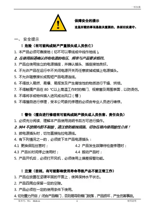
保障安全的提示这里所载的事项是极关重要的,务须切实遵守。
一、安全提示! 危险(有可能构成财产严重损失或人员伤亡)1. 本产品必须可靠接地(切不可以零线或中线作地线)。
2. 在使用前请确认供电电源的电压、频率与产品要求相符。
3. 产品应使用独立的电源插座,并确认插头、插座接地良好。
4. 不允许产品在运行中不关闭电源开关而任意拔掉或插上电源插头。
5. 不允许随意接长或剪短产品电源连线。
6. 不得放入易燃、易爆、易挥发及产生腐蚀性的物质进行干燥、烘焙。
7. 不得触摸产品在80 ℃以上高温工作时的箱门、视察窗及周围表面,以防烫伤。
8. 不得将手或物件插入进风或出风口(槽)9. 不得擅自进行修理,受本公司委托修理的必须由专业人员进行维修。
! 警告(擅自进行修理有可能构成财产损失或人员伤害、责任自负)1. 必须充分阅读、理解本产品使用说明书后方可进行操作。
2. 304不锈钢内胆不耐酸,请注意防腐蚀措施。
切勿在箱内使用酸性介质!3. 拔电源插头时,切勿直接拖拉电源线。
4. 有下列情况之一的,必须拔下本产品电源插头:4.1 更换保险丝管时; 4.2 产品发生故障待检查修理时;4.3 产品长时间停止使用时; 4.4 搬动产品时;5. 产品开机后,必须打开风机,必须使用上偏差报警功能。
! 注意(否则,有可能影响使用寿命导致产品不能正常工作)1. 产品应放置在坚硬牢固的平面上,使其保持水平状态。
2. 产品四周应保留一定的空隙。
3. 产品必须在一定的使用条件下使用。
4. 切勿重力开启/ 闭合产品箱门,否则易导致箱门脱落,产品损坏,产生伤害事故。
二、产品简介1. 外形图台式(适用DHG-9010~9245型)⑧①②③④⑨⑩⑾⑤⑥⑦图一①控温仪②电源开关③风门旋钮④电机开关⑤搁板⑥门封条⑦门把手⑧微型打印机⑨风机⑩循环风口⑾保险管座2. 结构功能概述DHG系列电热鼓风干燥箱由箱体、控温系统、电加热鼓风系统组成。
箱体由优质钢板冲制而成,表面喷塑处理,内胆采用优质镀锌板或镜面不锈钢板(供用户选择)组成。

G9000 SERIESMMS KITINSTALLATION MANUAL480/480 V 1000/1330/1500/1660/2000kVADocument No.: 200150-001Document: 4GBH0153 Rev. BMarch 2020IMPORTANT NOTICENever attempt to install, operate, maintain or dispose of this equipment until you have first read and understood all of the relevant product warnings and user directions that are contained in this Installation manual.The installation of this equipment must only be performed by qualified personnel.The Instructions contained in this manual are not intended to cover all of the details or variations in equipment or to provide for every possible contingency to be met in connection with installation, operation, or maintenance. Should further information be required or should particular problems arise which are not covered sufficiently the matter should be referred to the local TOSHIBA sales office.Nothing in this manual shall alter Toshiba International Corporation’s s tandard terms and conditions or the conditions of any written sales contract.Any Electrical or mechanical modifications to this equipment without prior written consent of TOSHIBA will void all warranties and may void UL/CUL listing. Unauthorized modifications may also result in personal injury, death, or equipment damage.UNINTERRUPTIBLE POWER SYSTEMIf additional information or technical assistance is required call TOSHIBA Customer Support Center at (877) 867-8773, or write to: Toshiba International Corporation, 13131 West Little York Road, Houston, TX 77041-9990 Attn: UPS Product Manager.Keep this manual with the UPS equipment.Job Number:Model Number:Serial Number:Application:Shipping Date:Date of Installation:Inspected By:Purpose and Scope of ManualThis manual provides information on how to safely install, operate, and maintain your TOSHIBA power electronics product. This manual includes a section on General Safety Instructions that describes the warning labels and symbols that are used throughout the manual. Read the manual completely before installing, operating, or performing maintenance on this equipment.This manual and the accompanying drawings should be considered a permanent part of the equipment and should be readily available for reference and review. Dimensions shown in the manual are in metric and/or the Imperial equivalent.TOSHIBA reserves the right, without prior notice, to update information, make product changes, or to discontinue any product or service identified in this publication.TOSHIBA is a registered trademark of TOSHIBA INTERNATIONAL CORPORATION. All other product or trade references appearing in this manual are registered trademarks of their respective owners.TOSHIBA shall not be liable for technical or editorial omissions or mistakes in this manual. Nor shall it be liable for incidental or consequential damages resulting from the use of information contained in this manual.This manual is copyrighted. No part of this manual may be photocopied or reproduced in any form without the prior written consent of TOSHIBA INTERNATIONAL CORPORATION.© Copyright 2020 TOSHIBA INTERNATIONAL CORPORATIONAll rights reserved.Printed in JapanContacting TOSHIBA Customer Support CenterThe TOSHIBA Customer Support Center can be contacted to obtain help in resolving any Uninterruptible Power System problem that you may experience or to provide after sales service support.Toshiba Customer Support Center8 a.m. to 5 p.m. (CST) – Monday through FridayTel (877) 867-8773Fax (713) 896-5212E-mail –**************************You may contact TOSHIBA by writing to:TOSHIBA INTERNATIONAL CORPORATION.SOCIAL INFRASTRUCTURE SYSTEMS GROUPPOWER ELECTRONICS DIVISION13131 West Little York Rd.Houston, TX 77041-9990Attn: UPS Product ManagerFor further information on Toshiba products and services, please visit our website at:/Table of ContentsTable of Contents ................................................................................................................................................................ i ii List of Tables ....................................................................................................................................................................... i ii List of Figures ...................................................................................................................................................................... i ii 1How to use this Manual .. (1)1.1Notice Icons (1)1.2Qualified Personnel (2)2OVERVIEW (3)3MMS KIT Parts List (4)4Installation Procedures (6)5Parallel Operation System Connection (12)List of TablesTable 2-1: Parts List of MMS KIT (4)Table 3-1: Dip Switch Setting on Parallel Interface Board (IFAU-16*) (10)Table 3-2: Status of Jumpers on Parallel Interface Board(IFAU-16*) (11)List of FiguresFigure 1-1: Parallel-Connection between UPSs (3)Figure 2-1: MMS KIT Parts Identification (5)Figure 3-1: Location of IFAU-16* MMS PCB Installation (1000kVA) (6)Figure 3-2: Location of IFAU-16* MMS PCB Installation (1330-2000kVA) (7)Figure 3-3: Cable Connections Between IFAU-16* and Others (8)Figure 3-4: Example of the Inside of Bypass Cabinet after Installation (1000kVA) (9)Figure 3-5: Dip Switch Location on Parallel Interface Board (IFAU-16*) (10)Figure 3-6: Example of Dip Switch Setting (10)Figure 3-7: Location of Jumpers on Parallel Interface Board(IFAU-16*) (11)Figure 4-1: Diagram of Power Wire Connections (Parallel Operation System) (12)Figure 4-2: Diagram of Power Wire and Control Wire Connection (Parallel Operation System) (13)Figure 4-3: UPS Module Parallel Interface Board (IFAU-16*) Interconnections (14)This Page Left Intentionally Blank1 How to use this ManualThis manual is designed for ease of use, giving the user easy and quick reference to information.This manual uses notice icons to draw attention to the user important information regarding the safe operation and installation of the UPS.1.1 Notice IconsThe notice icons used in this manual are explained below, and should be taken into account and adhered to whenever they appear in the text of this manual.Warning: A warning symbol shows potentially hazardous situation or condition which could result in personal injury or death, if not avoided.Caution: A caution symbol shows potentially hazardous situation or condition which could result in personal injury or equipment damage, if not avoided.Note: A Note symbol shows the information the user or the service personnel should observe during the UPS operation or service work. Prohibit: A prohibit symbol shows the act the user or the service personnel should NEVER perform during the UPS installation, operation or service work.Safety Recommendations: If any problems are encountered while following this manual, contact the Toshiba Customer Support Center.WARNINGCAUTION!NOTEPROHIBIT1.2 Qualified PersonnelOnly qualified persons are to install, operate or service this equipment according to all applicable codes and established safety practices.A qualified person must:1) Read this entire instruction manual carefully.2) Be skilled in the installation, construction or operation of the equipment and aware of the hazards involved.3) Be trained and authorized to safely energize, de-energize, clear, ground, lockout and tag circuits in accordancewith established safety practices4) Be trained and authorized to perform the service, maintenance or repair of this equipment5) Be trained in the proper care and use of protective equipment such as rubber gloves, hard hat, safety glasses,face shield, flash clothing, etc. in accordance with established practices6) Be trained in rendering first aid.2 OVERVIEWTOSHIBA G9000 Uninterruptible Power Supply Systems (UPS) need an MMS KIT whenever two or more UPSs are installed in parallel operation configuration.Each UPS requires an MMS KIT installed to allow it to complete the communication circuit with other modules.All UPSs must be de-energized when the MMS KITs are installed and the parallelinterconnections are established between the modules.CAUTIONUPS-1MMSKITUPS-2MMSKITUPS-nMMSKITFigure 2-1: Parallel-Connection between UPSs3 MMS KIT Parts ListTable 3-1: Parts List of MMS KITPart # Part name Qty Remarks1 Parallel Interface board: IFAU-16* (IF3) 12 Cable: CN95 (IFAU-16* - UPJR-D*) 1 1865mmHIF3-20D - HIF3-20D3A Cable: CN94 (IFAU-16* - UPJR-D*) 1 1820mm, J-10P - J-8P 3B Cable: CN96 (IFAU-16* - CSAU-07*) 1 1180mm, J-16P - J-16P 3C Wire: IFAU-16* GNDB(M3 clamp) - Ground bus bar (M4 clamp) 1 1170mm, Green3D Wire: IFAU-16* GNDC(M3 clamp) - Ground bus bar (M4 clamp) 1 1220mm, Green3E Wire: IFAU-16* GNDD(M3 clamp) - Ground bus bar (M4 clamp) 1 1070mm, Green4 Spacer: SQ-14(MBB-314) 85 Ferrite Core: E2530MRC 16 Dust Cover for LAN Jack: LD-DUSTBK6 12 6pcs/pack x 27 Screws (M3) 88 Spring washers (M3) 89 Flat washers (M3) 810 Screws (M4) 111 Cable Tie (T30R) 18 Use as necessary12 Cable Tie (T50R) 2 Use as necessary13 Base (ABMM-A-D) 15 Use as necessaryPart #1: Parallel Interface board (IFAU-16*) Part #2: CablePart #3A, 3B: Cable Part #3C, 3D, 3E: WirePart #5: Ferrite CorePart #4: SpacerPart #6: Dust Cover for LAN Jack Part #7: Screw(M3), Part #10:Screw(M4)Figure 3-1: MMS KIT Parts Identification4 Installation ProceduresFigure 4-1: Location of IFAU-16* MMS PCB Installation (1000kVA)Details of AFront View of bypass cabinet (with door open)IFAU-16*Screw(M3) x8(Upper right of bypass cabinet for 1000kVA UPS ) Step1 Step 1: Screw 8 spacers on the metallic plate (shown in red). Step 2: Secure the parallel interface board IFAU-16* on the spacerswith M3 screws.Step 3: Secure the ferrite core with an M3 screw (shown in pink). Step 4: Cover the modular connectors with the dust cover. Step 5A: Check location of Ground bus for the next step.Step2Step3Step4Spacer x8Dust cover x12Ferrite core Screw(M3) Unit: mm(Front cover)(Front cover)Ground busStep5ADetailsFigure 4-2: Location of IFAU-16* MMS PCB Installation (1330-2000kVA)Front View of bypass cabinet (with door open)Details of AIFAU-16*Screw(M3) x8(Upper right of bypass cabinet for 1330-2000kVA UPS ) Step 1: Screw 8 spacers on the metallic plate (shown in red). Step 2: Secure the parallel interface board IFAU-16* on the spacerswith M3 screws.Step 3: Secure the ferrite core with an M3 screw (shown in pink). Step 4: Cover the modular connectors with the dust cover. Step 5A: Check location of Ground bus for the next step.Step3Ferrite core Screw(M3)Unit: mmStep5ADetailsStep2Ground busSpacer x8Dust cover x12Step1Step4Figure 4-4: Example of the Inside of Bypass Cabinet after Installation (1000kVA)IMPORTANT NOTICEIn cases where there are large amounts of slack LAN cables after installation: Keep cables away from the power conversion circuits and conductorsin order to avoid interference in the parallel control communication. Do not roll cables as doing so may cause signal interference.PROHIBITIFAU-16*Parallel interface boardCSAU-07*Sensor board (Behind this panel)Ground BusExample of 1000kVAUPJR-D*Main control boardIFAU-16*Figure 4-5: Dip Switch Location on Parallel Interface Board (IFAU-16*)Table 4-1: Dip Switch Setting on Parallel Interface Board (IFAU-16*) System No.1 UPSNo.2 UPSNo.3 UPSNo.4 UPSNo.5 UPSNo.6 UPS2 by MMS All ON 1 and 2: ON3 to 8: OFF3 by MMS All ON All OFF 1 & 2: ON 3 to 8: OFF4 by MMS All ON All OFF All OFF 1 & 2: ON 3 to 8: OFF5 by MMS All ON All OFF All OFF All OFF 1 & 2: ON 3 to 8: OFF6 by MMSAll ONAll OFFAll OFFAll OFFAll OFF1 & 2: ON 3 to 8: OFFFigure 4-6: Example of Dip Switch SettingStep 8: Setup the dip switch on IFAU-16* according to Table 4-1.UPS#1 1 to 8: ON (All ON)UPS#2 ~ UPS#(N-1)1 to 8: OFF (All OFF)UPS#N 1 and 2: ON 3 to 8: OFFDip Switch(S1)Step 9: Make sure the status of Jumpers on IFAU-16* according to Table 4-2.JP1SHORT SHORTOPENFigure 4-7: Location of Jumpers on Parallel Interface Board(IFAU-16*)Table 4-2: Status of Jumpers on Parallel Interface Board(IFAU-16*)# Device Status1 JP1 SHORT2 JP6 SHORT3 JP11 OPENSOCIAL INFRASTRUCTURE SYSTEMS GROUPPOWER ELECTRONICS DIVISION13131 West Little York Rd., Houston, TX 77041Tel: 855-803-7087 Fax 713-896-5212US 800/231-1412 Canada 800/872-2192 Mexico 01/800/527-1204 Printed in Japan。
用户指南Legion Y9000P IAH7H、Legion Y9000P IAH7、Legion R9000P ARH7H和Legion R9000P ARH7用前必读使用本文档及其支持的产品之前,请务必先阅读和了解以下信息:•《常规安全与合规性声明》•《安全与保修指南》•《设置指南》第一版(2022年1月)©Copyright Lenovo2022.有限权利声明:如果数据或软件依照美国总务署(GSA)合同提供,其使用、复制或公开受编号为GS-35F-05925的合同的条款的约束。
目录关于本指南 (iii)第1章了解计算机 (1)前视图 (1)底座视图 (2)左视图 (3)右视图 (4)后视图 (5)底视图 (6)功能部件和规格 (7)USB传输速率声明 (8)运行环境 (9)避免身体持续接触特定的发热部分 (9)第2章开始使用您的计算机 (11)使用Windows (11)Windows帮助信息 (11)Lenovo Vantage和联想电脑管家 (11)Novo按钮菜单 (12)打开Novo按钮菜单 (12)双功能键 (12)热键 (12)无打印图标的双功能键 (13)FnLock开关 (13)第3章了解您的计算机 (15)管理电源 (15)检查电池状态 (15)为电池充电 (15)将兼容Power Delivery标准的USB Type-C充电器与计算机配合使用 (15)设置电源按钮行为 (16)电源计划 (16)设置操作模式 (16)更改UEFI/BIOS Setup Utility中的设置..16 UEFI/BIOS Setup Utility是什么 (17)打开UEFI/BIOS Setup Utility (17)启用或禁用Fool Proof Fn Ctrl (17)启用或禁用Always-on (17)启用或禁用Flip to Boot (17)在UEFI/BIOS Setup Utility中设置密码..17密码类型 (18)设置管理员密码 (18)更改或删除管理员密码 (18)设置用户密码 (19)启用开机密码 (19)设置辅助存储设备的密码 (19)更改或删除硬盘密码 (20)第4章帮助和支持 (21)常见问题 (21)自助资源 (21)CRU是什么? (22)您的产品型号适用的CRU (22)致电Lenovo (23)联系Lenovo之前 (23)Lenovo客户支持中心 (23)购买附加服务 (24)附录A声明和商标 (25)©Copyright Lenovo2022iii用户指南关于本指南•本指南适用于下面列出的Lenovo产品型号。
VSI9000系列变频器用户手册前言前言感谢您选用沃森电气科技(湖南)有限公司的VSI9000系列变频调速器(以下简称变频器)!该产品是本公司自主研发和生产的功能全面、性能优异的新一代变频器,融合了多种行业专业化需求和客户个性化需求,尽最大可能地满足您在各种控制场合的需要。
本产品符合GB/T12668-2002的国家标准的要求,通过了国家电控与配电设备质量监督检验中心的型式试验,并通过了ISO9001:2000国际质量体系认证。
本手册阐述了用户安装配线、参数设定、操作运行、故障诊断和故障排除、日常维护保养等相关事宜。
为确保能正确操作该系列变频器,发挥其优越性能,请在装机之前,详细阅读本手册,并请妥善保存,或将本手册交于该机器的使用者。
如对于本变频器的使用存在疑问或有特殊要求,请随时联络本公司的各地办事处或经销商,也可与本公司总部售后服务中心联系,我们将竭诚为您服务。
欢迎选用本公司系列变频器产品:✧VSI9000-G系列通用型变频器✧VSI9000-P系列风机、水泵专用型变频器✧VSI9000-ZS系列注塑机专用型变频器✧VSI9000-ZG系列注塑机一体化变频柜✧VSI9000-L系列拉丝机专用型变频器开箱时,请认真确认以下内容:1.产品是否有破损、碰伤现象,零部件是否有损坏、脱落现象;2.本机铭牌所标注的额定值是否与您的订货要求一致;3.如果装箱清单与您订货资料不符或产品有任何问题,请您随时联络本公司的各地办事处或经销商。
同时请说明产品型号、规格、产品编号、购买日期、破损程度等情况,以便我们第一时间内为您解决。
目录第一章注意事项...........................................11.1安全标识定义..........................................11.2安装注意事项.........................................11.3使用注意事项.........................................21.4报废注意事项.........................................4 第二章技术性能与指标.....................................52.1型号及其含义.........................................52.2铭牌说明.............................................52.3型号规格说明..........................................52.4技术指标说明..........................................7 第三章安装与配线...........................................93.1 安装环境要求.........................................93.2 外形与安装尺寸........................................93.3 操作面板尺寸........................................113.4 安装方向与空间......................................123.5 变频器的配线........................................133.6 主回路端子的配线....................................183.7 控制回路端子的配线..................................203.8 控制回路端子配线补充说明.............................223.9 通讯端子的配线.......................................233.10 选配件...............................................253.11 关于干扰.............................................27 第四章操作与运行..........................................294.1 操作面板.............................................294.2 面板操作方法.........................................334.3 变频器的上电.........................................36 第五章功能参数一览表.....................................375.1 基本运行参数.........................................375.2 频率设定参数.........................................385.3 起动制动参数.........................................385.4 辅助运行参数.........................................395.5 端子功能参数........................................435.6 保护功能参数........................................455.7 故障记录参数........................................455.8 闭环控制参数........................................465.9 简易PLC运行参数....................................475.10 摆频及测量参数......................................485.11厂家参数.............................................495.12状态监控参数.........................................49 第六章功能参数详细说明..................................506.1 基本运行参数.........................................506.2 频率设定参数.........................................566.3 起动制动参数.........................................576.4 辅助运行参数.........................................606.5 端子功能参数........................................666.6 保护功能参数........................................766.7 故障记录参数........................................786.8 闭环控制参数........................................796.9 简易PLC运行参数...................................846.10 摆频及测量参数......................................886.11 厂家参数............................................90 第七章故障诊断及处理.....................................917.1 故障现象及对策.......................................917.2 故障记录查询.........................................937.3 故障复位.............................................94第八章维护与保养..........................................958.1 日常检查与保养.......................................958.2 易损部件的检查与更换.................................978.3 存放及保修...........................................97 第九章应用范例............................................999.1 面板起停及面板调频...................................999.2 三线式控制模式1.....................................1009.3 三线式控制模式2.....................................1019.4 外部起停及外部电压调频..............................1029.5 外部控制方式、多段速运行.............................1029.6 可编程多段速控制....................................103第十章RS485通讯协议...................................10510.1 通讯概述...........................................10510.2 通讯协议说明.......................................10510.3 ASCII通讯协议......................................10610.4 RTU通讯协议.......................................118第一章注意事项为了确保您的人身、设备及财产安全,在使用变频器之前,请务必仔细阅读本章内容,并在以后的搬运、安装、运行、调试与检修过程中遵照执行。
XMT*-9000(常规PID)系列智能数显温度调节仪使用说明书一、概述XMT*9000系列仪表为智能型双排四位显示仪表,分别显示测量值和设定值,仪表为四键操作,参数快捷设置,参数符号显示简洁,输入信息方便,控制方式有二位式、时间比例、模糊PID, 具有参数自整定功能,仪表采用进口超强抗干扰芯片设计、质量可靠,红绿双色双排数码管分别同时显示测量值与设定值。
二、主要技术参数1、测量误差:±0.5F·S±1字,附加冷端补尝误差±1℃2、继电器输出触点容量:阻性负载220V /7A3、驱动固态继电器信号输出:驱动电流≥15mA,电压≥9V4、驱动可控硅脉冲输出:幅度≥3V,宽度≥40us的移相或过零触发脉冲5、控制周期:继电器输出为2~120秒,其它为2秒6、工作电源:85V~242V,50Hz7、工作环境:0~50℃,相对湿度≤85%RH,无腐蚀性及无强电磁辐射场合三、型号和规格常用输入信号及测控范围(特殊规格可另订货)传感器名称分度号测控范围镍铬-铜镍 E 0~700℃镍铬-镍硅 K 0~1300℃热电偶铂铑10%-铂 S 0~1600℃铁—铜镍 J 0~900℃铜电阻 CU50 -50.0~150.0℃热电阻铂电阻 PT100-199.0~200.0℃、-199.9~600.0℃四、仪表面板布置五、内部参数表序 号提示符名 称 说 明设定范围 出厂值 一级菜单 SP 控制点设定按▼▲键设定所需控制点的温度全范围随机1 AL1 报警12 AL2 报警2 只有一路报警时采用报警1,需上下限或上下偏差两路报警时才采用报警2作下限或下偏差报警,有报警输出时相应报警指示灯点亮全范围 随机3 SC传感器误差平移修正测量值有误差时可以通过此项值加或减修正, ±20.0 或±204 P 比例带 比例带= P×20, 其决定了系统比例增益的大小, P 越大, 比例的作用越小,过冲越小, 但太小会增加升温时间; 设置P=0,仪表转为二位式控制状态。
联想拯救者R9000P的键盘灯是怎么打开的?
联想拯救者是⼀款联想公司使⽤win10系统的游戏本的笔记本电脑。
配置是很⾼的,许多的玩家也是⽐较的喜欢。
特别是它的键盘很炫酷,有背光。
但是许多的使⽤者不知道应该怎么开启键盘的背光,今天我们就来说说联想拯救者R9000P是怎么开启键盘灯的吧。
下⾯就是拯救者R9000P开启键盘灯的⽅法。
⼀、按键开启
1、在拯救者系列电脑的键盘上⼀般都有键盘灯,⽽且在按键上都有键盘灯的标识,⼀般按FN+键盘灯按键即可。
2、这⾥我们可以看到空格(Space)键上有灯光的标志,所以是FN+空格键,按下组合键就可以开启。
⼆、在设置中开启
1、笔记本打开后在左下⾓找到开始菜单,或者按键盘上的开始菜单。
2、然后在点击开始菜单后找到设置项。
3、在控制⾯板中点击键盘选项。
4、点击键盘选项后选择点击键盘背光设置为开启即可。
那么以上就是关于联想拯救者R9000P怎么打开键盘灯的全部内容了,感谢⼤家的阅读!希望这篇教程解答能对⼤家有所帮助。
更多相关软件教程请关注。
联想拯救者R9000P分区的磁盘怎么合并怎么合并两个磁
盘分区
联想拯救者R9000P是⼀款⾮常不错的游戏本,可以为⽤户带来很好的游戏体验。
⼀般电脑磁盘都会分为两个或以上分区,有些⼩伙伴可能想将它们合并获得更⼤容量,那么联想拯救者R9000P怎么合并两个磁盘分区呢?
联想拯救者R9000P怎么合并两个磁盘分区?
通过磁盘管理可以实现win10分区合并,但是必要先删除相邻的分区,然后再使⽤“ 磁盘管理”中的“扩展卷”功能。
1、打开磁盘管理。
(键盘按下组合键WIN+R,输⼊“diskmgmt.msc”)
2、找到并删除要合并的分区例如,要将D盘合并到C盘,需要删除D。
右键单击D,然后选择“删除卷”。
请注意,存储在D:上的所有数据都将丢失。
如果有重要数据,建议在合并之前使⽤备份软件创建备份。
3、接下来,右键单击要合并到的分区,然后选择“扩展卷”选项。
4、按照扩展卷向导,接受默认选项以合并分区。
此功能⽆法直接解决分区合并问题,需要删除⼀个分区后并重建,需要删除数据。
PS:
卷⼤⼩总数:为当前磁盘调整后的最终容量估计
最⼤可⽤空间量:为当前磁盘最⼤可扩充的剩余容量
选择空间量:如果希望⾃定义当前磁盘增加的容量,可以⼿动输⼊容量⼤⼩以MB为单位,最⼤不超过“最⼤可⽤空间量”。
公式:卷⼤⼩总数 = 当前分区调整前容量 + 选择空间量
最⼤可⽤空间量 = 当前分区调整前容量 + 未指派空间容量
选择空间量 <= 最⼤可⽤空间量。