机械的外文翻译---TQ160履带式全液压推土机
- 格式:doc
- 大小:165.00 KB
- 文档页数:10
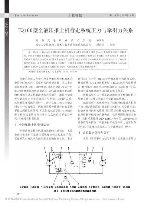

(倒)U形(电路)sink(电机)定子stator(电机)转子rotor 磁极magnetic pole叠装stacked up(汽车)启动:ignite (推土机)铲刀:shovel (仪表等的)指针:hand[在起动马达带动发动机运转时,观察发动机油压表指针是否摆动,能否建起润滑油压。
]建起:set up [建起某压力是指使压力达到某种程度]【机】联轴器:shaft co叩ling2 号极压锂基润滑脂No.2 lubricating grease with extreme pressure lithium2 位 5 通电磁换向阀Two-way and five - connection electromagnetic commutating/change valve60C 辅阀组60C auxiliary valve group60C 主阀组60C Main valve groupJ 型防尘圈J-type dust-proof ringkey switch:钥匙开关,电键开关,键式开关[由几档单健开关组成的形同琴键的开关组。
常见的有直键开关和键盘开关。
(IK)]0 形圈:O-ring 0 型密封圈:O-seal ring S 管总成 S-pipe assemblySAE 法兰片SAE Flange TQ160A 履带式全液压推土机:TQ160AFully Hydraulic Crawler Bulldozer U 型管接管U-pipe connecting pipe U 型管接头U・tube pipe fitting U 型管接头螺母:U-tube connecting nut; U-tube tie-in nut U 型卡U-clamp U 型螺栓U-boltY x型密封圈Yx-type seal ring Y 型管Y-shaped pipeY 字管组件Y-shaped pipe assembly 安全阀safety valve 安装板installation plate 安装垫块:Installation cushion block 安装块:Installation block 扒出棒scratching stick fittings 百叶窗:Shutter, louver 摆阀控制钢管Swing valve control steel pipe 摆阀油缸swing valve oil cylinder 摆阀油缸控制管(摆阀处)Swing-valve oil cylinder control pipe (at the swing valve)摆阀油缸连通管Swing-valve oil cylinder connecting pipe摆缸、插装阀、蓄能器油配管Oil Piping of Swing Cylinder, Cartridge Inserted Valve And Accumulator 摆缸调整swing cylinder adjustment摆缸控制钢管至主阀块胶管Rubber hose from swing cylinder control steel pipe to main valve block 摆摇机构及配阀swing mechanism and distributor valve 摆油缸回油胶管Swing valve oil cylinder oil return rubber hose 摆油缸进油胶管Swing valve oil cylinder suction rubber hose板:Board 拌筒agitation cylinder 包板:Wrapped sheet 保护圈back up ring保护套:Protective bush 背板:Back panel 泵车:Pump Truck/Truck-mounted concrete pump 保真度fidelity紧密耦合in close proximity (to)进口接头Inlet connector 进口小球阀接头体:Inlet small ball valve connector 进料feedstock, charge 进料斗Feed hopper; feeding hopper 进料斗用水管:Feed hopper water service pipe 进料门feeding door 进料速度charging rate 进料小锥:small discharge cone 进气总成:Air Intake Assembly 进水阀intake valve 经济性:economical efficiency 精称阀precise weightingvalve 精称门:precise measuring door 精滤器:secondary filter 精制螺栓:Refine bolt 静线压力:Static Pressure 救援车:wrecking car 卡:Clamp均方根值r.m.s. values=root mean square values 正铉时间函数sinusoidal time function 卡板:Clamp plate 卡箍:Clip 卡键:Clipping Key 卡键帽:Clipping Key Cap; Lock key cap 卡式接头:Bayonet joint 卡套Clamp sleeve 卡子:Shackle 开关柜门锁:Switchboard Door Lock 开口销:Splint pin 可编程程序控制器programmable Logic controller (PLC)空调胶管:Air conditioner rubber pipe 空调系统:Air Conditioning System 空气过滤系统air filtering system空间基波分量space-fundamental component空气滤清器:Air Cleaner 空压机air compressor 空载:no-load 孔用弹性挡圈:Ring baffle for hole 空载功率因数the no-load power factor孔用卡键:Clipping key for hole 控制板:Control board 控制电源按钮power supply control button 控制器:Controller 控制箱支架:Control box support 快速接头:Quick connector 跨导transconductance 扩展模块expansion module 拉扳:Arm tie 拉杆:Coupling bar 拉钩:Draw hook拉簧:Tension spring 劳力氏回转轴承:Rolex rotary bearing 冷凝风机:Condensation blower 拉力pulling force 压应力compressive stress 永久性变形permanent deformation 拉应力tensile stress钗接车架hinged frame 锁紧装置locking device冷凝器总成:Condenser Assembly 冷凝水:condensed water 冷却器Cooler冷却器回油胶管Cooler oil return rubber hose冷却器接头:Cooler connector冷却器座:Cooler seat冷却系统cooling system 冷却装置:Cooling system离地间隙:ground clearance of machine [简称“地隙”。


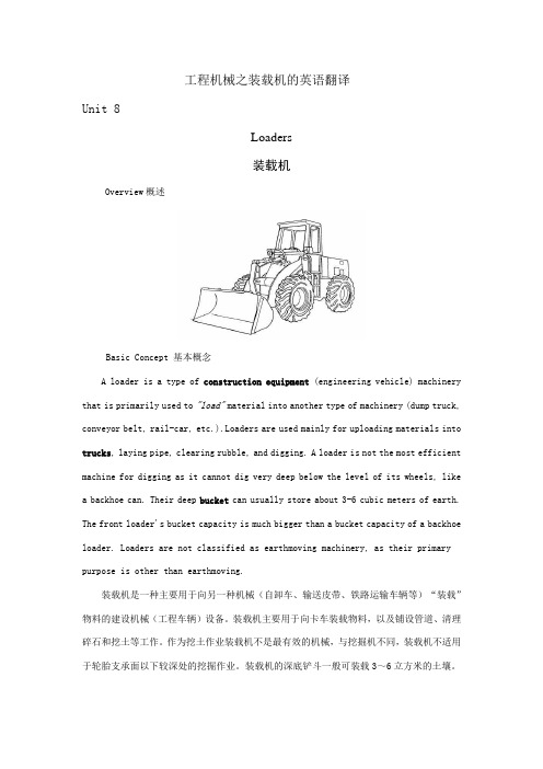
工程机械之装载机的英语翻译Unit 8Loaders装载机Overview概述Basic Concept 基本概念A loader is a type of construction equipment (engineering vehicle) machinery that is primarily used to "load"material into another type of machinery (dump truck, conveyor belt, rail-car, etc.).Loaders are used mainly for uploading materials into trucks, laying pipe, clearing rubble, and digging. A loader is not the most efficient machine for digging as it cannot dig very deep below the level of its wheels, like a backhoe can. Their deep bucket can usually store about 3-6 cubic meters of earth. The front loader's bucket capacity is much bigger than a bucket capacity of a backhoe loader. Loaders are not classified as earthmoving machinery, as their primary purpose is other than earthmoving.装载机是一种主要用于向另一种机械(自卸车、输送皮带、铁路运输车辆等)“装载”物料的建设机械(工程车辆)设备。

工程机械英汉词典Engineering Machinery English-Chinese Dictionary1. Excavator - 挖掘机2. Bulldozer - 推土机3. Crane - 起重机4. Loader - 装载机5. Forklift - 叉车6. Dozer - 推土机7. Roller - 滚压机8. Grader - 平地机9. Paver - 铺路机10. Dump Truck - 自卸车11. Concrete Pump - 混凝土泵12. Mixer Truck - 搅拌车13. Drill Rig - 钻机14. Skid Steer Loader - 小型装载机15. Backhoe Loader - 装载机兼挖掘机16. Asphalt Paver - 沥青铺路机17. Road Roller - 道路压路机18. Tower Crane - 塔吊19. Mobile Crane - 移动式起重机20. Crawler Crane - 履带式起重机21. Wheel Loader - 轮式装载机22. Hydraulic Excavator - 液压挖掘机23. Telescopic Handler - 伸缩臂叉车24. Articulated Boom Lift - 叉车25. Aerial Work Platform - 空中作业平台26. Scissor Lift - 剪叉式吊篮27. Tractor - 拖拉机28. Skid Loader - 履带装载机29. Motor Grader - 自行式平地机30. Bulldozer - 推土机以上是一些常见的工程机械英汉词汇,希望对你有所帮助。
挖掘机外文翻译外文文献中英翻译Excavator Translation: English Translation of Foreign LiteratureAbstract:The translation of foreign literature plays a significant role in acquiring knowledge and broadening horizons. In this article, we will explore the translation of foreign literature related to excavators. By analyzing various examples, we aim to provide an insightful understanding of the translation process and techniques involved in conveying the essence of foreign texts to the target language.1. IntroductionThe field of construction machinery presents numerous challenges when it comes to translation due to the technical nature of the content. Translating related literature helps engineers and professionals gain access to international best practices, safety guidelines, and advancements. One of the key areas within construction machinery is excavators, which serve as the focus of this article's English translation of foreign literature.2. Historical Background and EvolutionBefore delving into translations of foreign literature, it is essential to understand the historical background and evolution of excavators. The first excavators can be traced back to ancient civilizations such as the Egyptians and Greeks. Through detailed research and analysis, these ancient excavation methods have gradually evolved into the sophisticated machinery used today.3. Translation Techniques for Excavator-Related TerminologyTranslating technical terms accurately is crucial in preserving the integrity and clarity of the original text. When it comes to excavators, some terms might not have a direct equivalent in the target language. In such cases, the translator must employ various techniques like borrowing, calque, explanation, or using a closest possible translation. Balancing accuracy and readability is a crucial aspect of this translation process.4. Examples of Translated Excavator LiteratureTo demonstrate the translation techniques mentioned earlier, several examples will be provided in this section. These examples will range from user manuals, safety guidelines, to technical specifications and advancements. Through examining these examples, readers will gain insight into the specific challenges faced during translation and the strategies usedto overcome them.5. Cultural Considerations in Excavator TranslationsIn addition to technical accuracy, cultural considerations play a vital role in translating excavator literature. Different cultures may have varying perceptions and terminologies related to construction machinery. Translators need to be aware of cultural nuances to ensure that the translated materials are not only accurate but also culturally appropriate for the target audience.6. ConclusionIn conclusion, the translation of foreign literature on excavators is of great importance in the field of construction machinery. By accurately conveying the technical details, safety guidelines, and advancements fromforeign texts, engineers and professionals can broaden their knowledge and stay updated with international practices. The translation process involves employing various techniques and considering cultural aspects. As a result, it is crucial for translators to possess both technical expertise and cultural sensitivity when undertaking such translations.Through this article, we have explored the significance of excavator translation, the challenges faced, and the techniques employed. It is the bridge that connects language barriers, facilitates learning, and fosters advancements in the field.。
农业用机械设备外文文献翻译、中英文翻译、外文翻译在公元前1世纪,中国已经开始推广使用耧,这是世界上最早的条播机具,在北方旱作区仍然得到应用。
1636年,希腊制造了世界上第一台播种机。
1830年,俄国人在畜力多铧犁上加装播种装置制成了犁播机。
1860年后,英美等国开始大量生产畜力谷物条播机。
20世纪后,牵引和悬挂式谷物条播机以及运用气力排种的播种机相继出现。
50年代,精密播种机开始得到发展。
中国从20世纪50年代开始引进谷物条播机、棉花播种机等。
60年代,中国先后研制成了悬挂式谷物播种机、离心式播种机、通用机架播种机和气吸式播种机等多种类型,并研制成了磨纹式排种器。
到70年代,中国已经形成了播种中耕通用机和谷物联合播种机两个系列,并成功研制出了精密播种机。
播种机具有播种均匀、深浅一致、行距稳定、覆土良好、节省种子、工作效率高等特点。
正确使用播种机应注意以下10个要点:1)在进田作业前,要清理播种箱内的杂物和开沟器上的缠草、泥土,确保状态良好。
对拖拉机及播种机的各传动、转动部位,按照说明书的要求加注润滑油,尤其是每次作业前要注意传动链条润滑和张紧情况以及播种机上螺栓的紧固情况。
2)机架不能倾斜,播种机与拖拉机挂接后,不得倾斜,工作时应使机架前后呈水平状态。
3)搞好各种调整,按照使用说明书的规定和农艺要求,将播种量、开沟器的行距、开沟覆土镇压轮的深浅调整适当。
Seeder Tips1.Pay n to adding good quality seeds to the seed box to XXX。
Make sure there are no small。
broken。
or impure seeds。
Also。
XXX.2.Before large-scale seeding。
conduct a 20-XXX.3.Choose a suitable route for the seeding machine to move ina straight line at a constant speed。
附录二:外文技术资料及中文翻译1、英文技术资料Belt ConveyorFIELD OF THE INVENTIONThe present invention relates to a belt conveyor having a circulating conveying belt, having carrying rollers, which are arranged between the top strand and the bottom strand of the conveying belt, and having a drive device and a force-transmission device for moving the conveying belt.BACKGROUND OF THE INVENTIONIt is known from practice for force to be transmitted from the drive device to the conveying belt of a belt conveyor via friction fitting. The friction between a driven carrying roller and the conveying belt, for example, may even be sufficient for this purpose. The rest of the carrying rollers are mounted in a movable manner and rotate along.DE 42 44 170 C2 discloses a belt conveyor having an endless conveying belt, the latter being driven by means of a force-transmission device which is present in the form of a friction wheel. A drive shaft extends beneath the bottom strand of the conveying belt. On the inner radius of the belt curve, a motor is connected as a drive device to the drive shaft and, in the region of the outer radius, a friction wheel is seated on the drive shaft and is in contact with the outer surface of the conveying belt. In this case, the friction wheel interacts with a carrying roller functioning as counterpressure roller. The drive shaft is mounted such that it can be moved at an angle both in the region of the outer radius and in the region of the inner radius of the belt curve. The movable-angle mounting of the drive shaft allows adaptation of the extent to which the friction wheel is pressed against the conveying belt in proportion to the actual load. In this way, the wear is reduced if, in part-load operation, the conveying belt is only subjected to the contact-pressure force which is necessary for this purpose.Although the belt conveyor known from DE 42 44 170 C2 reduces the wear of the conveying belt, it cannot rule it out altogether. The task of conveying foodstuffs or other goods which are to be kept clean involves, in addition to the mechanical damage to the conveying belt, the aspect of hygiene and of keeping goods clean. The abraded surface particles of the conveying belt could have a considerable adverse effect on the quality of the goods which are to be conveyed. Moreover, the known belt conveyor requires an extremely high level of structural outlay as far as the movable mounting of the separate drive shaft is concerned. SUMMARY OF THE INVENTIONTaking as departure point the belt conveyor known from DE 42 44 170 C2, the object of the invention is to specify a belt conveyor of the type in question which largely rules out any adverse effect to the surface of the conveying belt of the belt conveyor by the force-transmission device. According to a particularly preferred configuration, the belt conveyor is intended to require just a low level of structural outlay.The above object is achieved by the features of Patent claim 1. According to the latter, a belt conveyor of the type in question is configured such that a pair of elements which interact with one another with a form fit is provided for force-transmission purposes, and that one element is assigned to the force-transmission device and the other element is assigned to the conveying belt.According to the invention, it has been found that the surface of the conveying belt is not adversely affected as a result of the action of the force-transmission device if a separate pair of elements is providedin order to realize force transmission. It has also been found that the use of a pair of movement-converting elements which are known per se and interact with one another with a form fit largely eliminates the disadvantages which are known in the case of friction-fitting movement conversion, in particular wear and abrasion.According to a preferred exemplary embodiment of the belt conveyor according to the invention, the pair of elements could be present as toothed ring and toothed belt, the tooth flanks of the toothed ring and of the toothed belt interacting with one another. It would be possible for the toothed ring to be assigned to the force-transmission device and for the toothed belt to be assigned to the conveying belt.As far as a particularly low level of structural outlay is concerned, a preferred configuration of the abovementioned exemplary embodiment provides that the toothed ring is assigned to a carrying roller, and the latter thus simultaneously assumes the role of the force-transmission device. Via a journal projecting from the carrying roller, the drive takes place by means of a motor. The toothed ring could be plugged onto the carrying roller and fixed releasably—for example via a shaft/hub connection or a feather key—to the same. In the case of a plugged-on toothed ring, it is advantageous that it is possible to use carrying rollers which are already present. It is particularly advantageous for each carrying roller to be assigned at least one toothed ring. Over the entire running path of the conveying belt, it would then be the case that the toothed belt and the toothed rings interengage and move the conveying belt in a dimensionally stable manner. Corresponding to the toothed ring or rings which is/are arranged between the top and bottom strands and belongs/belong to the preferred configuration mentioned above, the toothed belt is arranged on the underside of the conveying belt, and extends in the running direction of the same. Arranging the toothed belt on the underside of the conveying belt once again ensures that the top side of the conveying belt, which is charged if appropriate with goods which are to be kept clean, is not subject to any force transmission, mechanical damage or production of abrasion particles or other contaminants.An expedient development of the preferred configuration of the belt conveyor according to the invention makes provision for the toothed ring to be arranged at the end of the carrying roller. As a result, on the one hand, straightforward maintenance of the force-transmission device is made possible and, on the other hand, this arrangement is also more cost-effective than a, for example, central arrangement. Direct force transmission over a short distance is achieved by a journal for the connection of the drive device projecting from that end of the carrying roller which is provided with the toothed ring.It is particularly advantageous if the toothed belt extends in the region of the side border of the conveying belt. As a result, on the one hand, straightforward production of the conveying belt with the toothed belt is made possible by the direct relationship to the border region and, on the other hand, a role is also played here by the accessibility to the pair of elements for maintenance purposes and, of course, by the coordination between the toothed belt and the arrangement of the toothed ring.In addition to toothed belts and toothed rings with normal toothing, it would also be possible to realize multisplining. This further reduces undesired sliding and thus wear, heating and noise development. In order to absorb high tensile forces, it would be possible for Kevlar filaments to be incorporated in the toothed belt, which usually consists of plastic. It would be possible for the conveying belt to be produced with the toothed belt by welding, vulcanizing or adhesive bonding.According to a particularly preferred configuration, it would be possible for the toothed belt to be a constituent part of a toothed- belt component which is of essentially U-shaped design in the transverse direction of the toothed belt. The U-shape makes it possible for the toothed- belt component simply to be plugged onto the border of the conveying belt until the border region has come into contact with the base part between the U-legs. The inner surface of the toothed- belt component may have been provided with adhesive beforehand. As a result of its shaping and of being produced in this way, the toothed- beltcomponent engages around the side-border region of the conveying belt.While the toothed belt of the conveying belt is subjected to compressive force by the toothed ring, and this largely rules out detachment of the toothed- belt component on the underside of the conveying belt, a counterpressure device could be provided in order to secure that region of the toothed- belt component which extends on the top side of the conveying belt. In design terms, the counterpressure device could be present in the form of an arm which acts on the U-leg of the toothed- belt component on the top side and thus constantly presses the same onto the top side of the conveying belt.As far as reliable guidance is concerned, it would be possible for the toothed belt or the toothed- belt component containing the toothed belt to form a bead. A bead ridge is thus produced over the length of the conveying belt. In the case of a U-shaped toothed- belt component, the bead ridge extends in each case at the free ends of the U-legs, at a distance from the border of the conveying belt, the distance depending essentially on the width of the toothed belt. As an alternative to a bead ridge, it would be possible for the toothed- belt component or for the straightforward toothed belt also to have at least one beveled free end. The guidance measure taken on the toothed belt or on the specific toothed- belt component is provided in order that a guide roller or a pair of guide rollers acts on the beveled surface or on the bead or bead ridge. The guidance measure explained above could be taken equally well in the case of belt curves and straight belt lines and of belt S-shapes bridging different heights.In the case of belt curves, the force acting on the conveying belt is directed toward the inner radius of the belt curve, with the result that the guide rollers, in an advantageous manner which is known per se, could have inclined running surfaces. Correspondingly angled retaining arms as a constituent part of retaining structures for the guide rollers could be arranged in each case in the region of a carrying roller. The guide rollers could be arranged in pairs on the top strand and on the bottom strand of the conveying belt.It should be emphasized at this point that, with the abovementioned configuration of the belt conveyor according to the invention having the bead or beveled free ends, two functions are combined in the pair of form-fitting elements. Not only the force transmission, but also the guidance of the conveying belt, takes place. The dimensional stability of the conveying belt is advantageously increased by the pair of form-fitting elements with the specific configuration of the toothed belt or of the toothed- belt component for action of the guide rollers thereon.In the case of the already cited design of the belt conveyor in the form of a belt curve, the carrying rollers are of conical design and the toothed ring is arranged at the larger-diameter end of the respective carrying roller, that is to say on the outer radius of the belt curve. The drive device is present as a motor and is assigned to the first carrying roller of the belt curve. The form-fitting interengagement of the toothed wheel and toothed belt takes place in the region of each carrying roller, the form fit, in relation to the first, motor-driven carrying roller, serving for force-transmission purposes and, in relation to the rest of the rollers, serving for guiding the conveying belt.The previously explained principle of force transmission via a pair of elements which interact with one another with a form fit could also be used in the case of a straight belt line or in the case of a height-changing belt S-shape. Here, the carrying rollers are of a cylindrical design and the force transmission takes place—as with the belt curve—at a first carrying roller, while the following carrying rollers, likewise equipped with the pair of form-fitting elements, serve for guiding the conveying belt. In contrast to the belt curve, however, it would be possible, in the case of the straight belt line or in the case of the belt S-shape, for the pair of elements to be arranged at the two free ends of the respective carrying roller and on the two border regions of the conveying belt. It would thus be possible specifically for the two border regions of the conveying belt to have a toothed belt or a toothed- belt component which interacts with the toothed rings at the two free ends of each carrying roller. Furthermore, it would also be possible, with these types of construction of the belt conveyor according to the invention, to provideguide rollers.A further advantage of the preferred embodiment of the belt conveyor according to the invention, the toothed ring and toothed belt interacting, consists in the improved capacity for controlling the belt speed in accordance with the current loading. It would be possible to provide a control device which senses a change in the speed by corresponding measuring sensors and adjusts the power of the drive device in line with the safety regulations.In comparison with the force transmission realized by friction fitting, the belt conveyor according to the invention not only has the advantage of better capacity for control, but also has the advantage that the conveying belt has a high level of dimensional stability as a result of the guidance by means of the pair of form-fitting elements and by means of the pairs of guide rollers and can be subjected to higher torques. Overall, it is possible to achieve an increased level of drive power during start-up. In the case of the belt conveyor according to the invention being designed in the form of a belt curve with an inner radius of 400 mm, the carrying rollers rotate at 230 rpm at a maximum speed of 1.5 m/sec.2、中文翻译带式运输机一、领域的发明本发明涉及一种具有循环带式输送机输送带,有托辊,这是链之间的顶部和底部的传送带链排列,有一个传动装置和一个移动传送带力传动装置。
工程机械专业英语推土机(Bulldozers)3Unit11newwords一、单词列表1. Bulldozer(名词):推土机2. Blade(名词):刀片,推土机的铲刀3. Cab(名词):驾驶室4. Track(名词):履带5. Transmission(名词):传动系统6. Hydraulics(名词):液压系统7. Grader(名词):平地机8. Excavator(名词):挖掘机9. Loader(名词):装载机10. Dozer(名词):推土机(口语表达)二、单词解析1. Bulldozer:推土机是工程机械中的一种,主要用于土地平整、挖掘和装载等工作。
2. Blade:推土机的铲刀,用于推土、挖土和装载物料。
3. Cab:驾驶室是推土机操作员的工作场所,通常配备有座椅、控制系统和显示器等。
4. Track:履带是推土机行走部分的关键部件,使推土机能在复杂地形上稳定行驶。
5. Transmission:传动系统负责将发动机的动力传递到推土机的各个工作部件。
6. Hydraulics:液压系统是推土机实现各种动作的关键,如铲刀升降、转向等。
7. Grader:平地机,与推土机类似,主要用于道路、场地平整作业。
8. Excavator:挖掘机,用于挖掘土石方,与推土机在功能上有所区别。
9. Loader:装载机,主要用于装载、搬运物料,与推土机在某些场合可互换使用。
10. Dozer:推土机的口语表达,常用于施工现场的交流。
三、实用例句1. The bulldozer is equipped with a powerful blade for efficient earthmoving.(这台推土机配备了一个强大的铲刀,用于高效的土石方作业。
)2. The operator sits in the cab, controlling thebulldozer with ease.(操作员坐在驾驶室里,轻松地控制着推土机。
Crawler Hydraulic Bulldozer TQ160TQ160A in the reference and absorption of foreign advanced technology, based on a self-developed hydrostatic drive track-type bulldozer. It uses the procurement of international purchasing parts, bulldozer on the performance of the engine, the main hydraulic pump, drive motor and key electrical components of the international brand-name products are used to ensure that the aircraft of superior performance, while also integrated into a number of design Innovative technology1, Main technical parametersDeutz Engine BF6M1013E (imported)Rated Power (kW) / speed (r / min) 137 / 2 300Total mass (kg) 16 500Track center distance (mm) 1 880Ground contact length (mm) 2 430Track Width (mm) 510Ground pressure (kPa) 67Blade (L × H) (mm) 3 420 × 1 150Soil depth of maximum shear blade (mm) 545Blade maximum lift height (mm) 1 095Minimum turning radius (without blade) (mm) 1 900Speed (km / h) forward two block: 0 ~ 4.5,0 ~ 10Back two block: 0 ~ 4.5,0 ~ 102, the main structure and performance characteristics2.1 set axis units frameShown in Figure 1, sets the frame with swing shaft structure, which with the balance beam is connected via a dedicated articulated mechanism to fully meet the bulldozer work in Taiwan, the swing frame required; and racks through the fixed pivot independent of each other , pivot detachable structure, most of the weight machine passed directly to the frame through the pivot, thus greatly reducing the transmission ofthe bulldozer was at work, the impact and prolong the life of the transmission system; pendulum shaft structure Province frame to the traditional structure of the ramp platform support, simplified structure, improved processing technology, reduce production cost and increase rigidity; the final drive and sets the frame separately, without dismantling the case of Taiwan, a direct repair frame Final drive, easy maintenance.2.2 Work equipment controlsWorking. device control by the pilot control system, all actions Blade: upgrade, down, left and right tilt and float, complete with a handle and manipulate very labor-saving, light sensitive, accurate and reliable. Figure 2 shows the blade control handle. At the same time, the aircraft are also used with ripper pilot hydraulic control systems.2.3 Driving and parking brake control systemHydraulic proportional control servo drive control system, the system consists of a dedicated pilot gear pump oil, the forward, backward, left turn and driver-specific in situ hydrostatic steering performance focused on a handle, while the handle is integrated tra vel speakers , speed, and reversing alarm switch block, which greatly simplifies the control system running, so the driver can concentrate on work.When the control lever is in neutral position, the pump will cut off access to the variable ratio power servo control valve oil, zero displacement hydraulic pump, hydraulic motor lock, the vehicle can not walk, so as to achieve the purpose of the safety brake. To ensure the safety of vehicles, aircraft design is still a driven gear shaft safety brake for parking (or emergency parking brake), the brake is normally closed, when the engine stalled or moving the operating handle is in neutral position, the brakes closed under spring force, to achieve braking; and when the manipulation of moving the handle, the role of the control to open the brake fluid, so that bulldozers driving. Parking brake lever by the brake control and emergency brake button control, manipulation of any of them, can achieve braking.2.4 TransmissionShown in Figure 3, TQ160A bulldozers closed double-loopdouble-pump hydraulic system, driven by the engine double variable pump, piston-type variable hydraulic motor driven, hydrostatic drive system components, and finally tracked vehicle driven by the final drive and steering. Each side of the track system by an independent hydrostatic drive, so that bulldozers can easily achieve pivot turn, greatly enhanced the mobility of the bulldozers and work suitability.Our unique control system of the engine closed-loop constant power control system, the central controller (CPU) load based on the size of bulldozers at any time suffered moderator pump swashplate angle control drive system flow to the machine to automatically according to the size of external load adjust speed, fully meet the bulldozers at work on speed and power requirements to ensure the efficiency of machine, to prevent overloading the engine and can make full use of engine power.TQ160A bulldozer driven by electric motor two-block variable motor, the whole block forward and backward are the two to meet the needs of different conditions.2.5 Intelligent alarm systemTQ160A three bulldozers with complete intelligent alarm system, through the instrument panel meters, LED, buzzer and LCD monitors to keep it informed of the vehicle running all kinds of information, such as: engine temperature, oil pressure, hydraulic oil temperature, working hours, engine speed and battery charge and discharge; the sensors to collect information processed by the CPU through the liquid crystal display to determine a text or voice expressed in the form, such as thework of the solenoid valve opening, engine speed and the machine appears failure, etc.; The display can also work to select the operating mode of the engine.2.6 MaintenanceAs a result of hydrostatic transmission system, eliminating the torque converter drive bulldozers, power transmission, a central transmission, steering clutches and steering brakes and other components, greatly simplifying the whole structure, so that maintenance of the transmission system is convenient.In order to facilitate the hydraulic system pressure measurement, to help repair and maintenance, the aircraft pressure measurement using a centralized approach, all the measurement points are located in the left cabinets, open the box lid can see, very convenient. The aircraft left engine cover, left box spring cover support oil and gas are used, open save time and effort.2.7Modeling and machine vision drivers.Whole shape of beautiful and unique machine, the cab structure with six sides, so as to increase the door width of the cab, front blade to enhance the hydraulic cylinder, compared with the traditional style, greatly improved vision.2.8 configurationROPS / FOPS cab, straight tilting blade and the machine after the traction frame is a standard configuration. At the same time, users can use optional different angle blade, ripper, and heating and air conditioning.TQ160履带式全液压推土机TQ160A是在参考和吸收国外先进技术的基础上,自行研制开发的一种静液压驱动履带式推土机。