Microchip SPI 串行EEPROM 器件的建议用法 01040a_cn
- 格式:pdf
- 大小:342.99 KB
- 文档页数:8

写eeprom注意事项
1. 需要使用正确的编程器和相应的编程软件。
2. 在编程之前需要备份原始EEPROM数据,以防意外发生导致数据丢失。
3. 确保EEPROM芯片正确连接到编程器上,以避免烧录错误。
4. 保持EEPROM芯片在合适的电压范围内,以避免损坏。
5. 在编程之前,需要清除EEPROM的保护位,这通常可以在编程软件中完成。
6. 如果需要修改EEPROM的数据,请确保所有修改都是有效的,并遵守设备的规格说明。
7. 在编程结束后,需要读回编程器中的EEPROM数据进行验证,以确保编程成功。
8. 最后,需要将EEPROM芯片从编程器上拔下来,并将其正确插入到设备中。

SPI FLASH 编程器安装使用说明编程器安装:通用串行EEPROM编程器安装操作非常简单,首先使用随机的并口数据线,将编程器与计算机并口联接,然后将电源线分别接在编程器电源插口口。
此时开机,编程器绿色电源指示灯应亮。
运行随机光盘上驱动安装程序,按照提示,一步步安装(如果没有特殊要求,全部采用默认安装)安装完成后,点击桌面的编程器驱动图标Elnec Pg4uw,双击运行。
在显示编程器类型选择中,由于我们的编程器是串行编程器,因此选择[SEEPROG],然后点“连接”,即可进入驱动界面。
选择[SEEPROG]确认后,即可进入编程器驱动控制界面。
注意:通用串行EEPROM编程器,需要通过LPT1(打印口)通信,因此要确定你的计算机有并口,并且并口已经默认设置为LPT1端口。
可按以下步骤,检查你的计算机LPT端口属性。
1、点击“开始”菜单。
2、鼠标右击“我的电脑”并选择菜单“属性”3、在“系统属性”对话框中选择“硬件”并点击“设备管理器”4、在“设备管理器”对话框中选择“端口”“(Com和LPT)”双击,显示全部COM和LPT端口;你的计算机至少要有一个LPT端口。
如果显示一个或多个LPT端口,而没有LPT1端口,必须将其中的一个LPT端口改为LPT1端口(接上面1-4操作)。
5、双击需要修改的LPT端口以显示端口的属性。
6、在“LPT端口属性”对话框中选择“端口设置”7、将LPT端口号改为LPT18、点击确定9、重启操作系统(即使系统没有要求重新启动,也必须重启系统,这样LPT1端口才可使用)操作说明:通用串行EEPROM编程器中文驱动,界面简洁明了;而且编程器设置是自动完成的,因此在编程过程中,不需要做复杂的设置,都是由控制程序自动来完成的。
在进行读写操作时,我们只要将芯片插到编程器上(或使用转接座),然后在驱动中选择芯片的型号,即可进行读写操作。
下面我们以WINBOND W25X40芯片为例,做一说明;W25X40芯片为DIP8芯片;如是其它封装的芯片,需要选择对应的转接座。
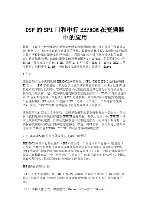
DSP的SPI口和串行EEPROM在变频器中的应用摘要:实现了一种全集成可变带宽中频宽带低通滤波器,讨论分析了跨导放大器-电容(OTA—C)连续时间型滤波器的结构、设计和具体实现,使用外部可编程电路对所设计滤波器带宽进行控制,并利用ADS软件进行电路设计和仿真验证。
仿真结果表明,该滤波器带宽的可调范围为1~26 MHz,阻带抑制率大于35 dB,带内波纹小于0.5 dB,采用1.8 V电源,TSMC 0.18μm CMOS工艺库仿真,功耗小于21 mW,频响曲线接近理想状态。
关键词:Butte1 引言变频器的开发中我们选用TMS320F240芯片做主CPU,TMS320F240系列是美国TI公司于1997年推出的,专为数字电机控制和其它控制应用系统而设计的16位定点数字信号处理器。
它将数字信号处理的高速运算功能与面向电机的强大控制能力结合在一起,成为中低端变频器理想的主控芯片。
F240片内外设包括双10位A/D转换器,带有锁相环PLL时钟模块,带中断的看门狗定时器模块,串行通信接口SCI及串行外设接口SPI,另外,还集成了一个事件管理模块EVM。
因此,TMS320F240基本能满足笔者变频器设计的要求。
变频器有几百甚至上千个参数,这些参数值都要求系统断电后不能丢失,在设计中我们选用非易失性存储器EEPROM保存数据。
每次上电时,从EEPROM中读取上次参数的设定值,以保证变频器运行状态的连续性,同样每次断电时,也要保存变频器此次运行的参数设定情况,以便开机时读取。
本文阐述了变频器开发中F240扩展EEPROM(X5168)的设计思路和实现过程。
2 对TMS320F240的串行外设接口(SPI)的说明TMS320F240的串行外设接口(SPI)模块是一个高速同步串行输入/输出端口,它允许F240控制器和片外外设或其他控制器进行串行通信,在通信过程中,SPI能够以任意给定的传输速率对具有可编成长度(1-8位)的串行比特流进行收发。

UNI/O™ Serial EEPROMsSingle I/O Bus Interface/UNIONeed more microcontroller pins for new features?Want to stay with a low pin-count microcontroller rather thanswitching to a more expensive one?Microchip’s new UNI/O serial EEPROM uses only ONE connection to the host microcontroller. This compares to two or three pins for I 2C™, and three to six pins for Microwire or SPI buses. This new, proprietary bus offers advanced features like a status register and write protection on demand, along with all I/O, memory array and command functions through a single pin.■ Single I/O Interface■ 1-16 Kbit Memory Densities ■ 1.8-5.5V Operating Voltage■ 10-100 KHz Operating Frequency ■ 1 Million Erase/Write Cycles ■ Software Write Protect – ¼, ½ or Full Array ■ Status Register■ Set/Erase entire memory with a single command ■ ESD Protection > 4 KV ■ Noise Filtration Circuitry ■ Packaging: 3-pin SOT-23 8-pin SOIC, MSOP & TDFN ■ Temperature: Industrial (-40ºC to +85ºC) Extended (-40ºC to +125ºC)Advanced FeaturesBenefi ts/UNIOA single I/O EEPROM can simplify your design andreduce system cost■ Free up pins on the MCU – Add a new feature to your application – Move to a smaller MCU■ Free up pins on your connector – Smaller connector = lower cost ■ More compact designNew Communications StandardUNI/O bus: First introduced on serial EEPROMs■ Manchester Communications – Clock and data in a single serial bit stream – Signal transition in the middle of bit period ■ MCU establishes data rate■ EEPROM tracks data rate − Frequency and Phase ■ Software AddressableUse your existing hardware■ UNI/O EEPROMs can fi t in existing sockets– Pin-out similar to I 2C and SPI EEPROMs– 8-pin packages share Vcc, Vss and Data LineGet Started With a Simple Evaluationi hi/UNIO Current EEPROM 8-lead Pin OutsUse Microchip’s software drivers■ UNI/O software drivers available for many popular microcontrollers ■ New drivers coming/UNIOStatus RegisterHV GeneratorI/O Control LogicCurrent-Limited Slope ControlEEPROM ArrayPage LatchesY DecoderSense Amp.R/W ControlMemory Control LogicX DecI/O Communication• Manchester encoding/ decoding• Synchronization circuitry • Software addressingRobust Interface• Current limited• Protection during short circuits and bus confl icts• Superior EMI performanceMemory Control Logic• Controls for internal clock and data• Byte or page write • Erase all or set allStatus Register• Write In Process (WIP) bit • Write Enable Latch (WEL) bit • Block protection bits– Write protect for ¼,½ or full arrayEEPROM Memory• Density: 1K, 2K, 4K, 8K & 16K • Endurance > 1 Million Cycles • Data Retention > 200 YearsPage Buffer• 16 byte pageGNDSCIOV CCMPLAB® Starter Kit for Serial Memory Products(Part Number DV243003)/UNIOTotal Endurance™ SoftwareMicrochip’s Total Endurance Softwareprovides you with unprecedented visibility into SerialEEPROM based applications. Describe your system to an advancedmathematical model (with a friendly human interface), and it will predict the performance and reliability of the Serial EEPROM within that environment. Design trade-off analysis that formerly consumed days or weeks can now be accomplished in minutes with a level of accuracythat delivers a truly robust design.mathematical model (with afrieResources to help you get started quickly ...Additional ResourcesMicrochip Advanced Part Selector (MAPS): /mapsGetting Started with UNI/O™ Webinar: /webseminarsOver 50 different application notes, many with source code options can be found at: /appnotes Get started with Microchip’s Serial EEPROMs in four easy steps: /eepromUNI/O Bus Software DriversMCU Family Device ArchitectureLanguage Timer ResourcesData Bus Instruction WordPIC® MCU PIC10F202PIC12F508PIC16F5058-bit 12-bit Assembly Firmware PIC MCU PIC12F609PIC16F6108-bit 14-bit Assembly Firmware PIC MCU PIC12F683PIC16F6168-bit 14-bit AssemblyHW Peripheral PIC MCU PIC12F683PIC16F6168-bit 14-bit C HW Peripheral PIC MCU PIC18F12208-bit 16-bit Assembly Firmware PIC MCU PIC18F24J108-bit 16-bit AssemblyHW Peripheral PIC MCU PIC18F24J108-bit 16-bit C HW Peripheral PIC MCU PIC24FJ128GA01016-bit 24-bit C HW Peripheral dsPIC® DSC dsPIC33F256GP71016-bit 24-bit C HW Peripheral PIC MCU PIC32XXX 32-bit 32-bit C HW Peripheral ARM7 Core AT91SAM7S25632-bit 32-bit C HW Peripheral 805189LPC9528-bit 8-bit AssemblyHW Peripheral 805189LPC9528-bit 8-bit C HW Peripheral MSP430MSP430F123216-bit16-bitCHW PeripheralIncrease productivity, reduce time to market and create a rock-solid design using this sophisticated developmentsystem. The MPLAB Starter Kit includes everything necessary to quickly program and develop a robust and reliable Serial EEPROM design, and reduce the time required for system integration and hardware/software debug.■ Windows® 2000, XP and Vista™ operating systems ■ Total Endurance™ software model■ MPLAB Starter Kit board and user interface software ■ Quick start guide■ Serial EEPROM sample packI d ti it d ti t k tdFor the most up-to-date information visit: /UNIOUNI/O Product FamilyDevice Density(bits)Organization Page Size (bytes)Operating Voltage Temperature RangePackages 11AA0101K 128 x 816 1.8-5.5V I TT , SN, MNY , MS, P 11LC0101K 128 x 816 2.5-5.5V I, E TT , SN, MNY , MS, P 11AA0202K 256 x 816 1.8-5.5V I TT , SN, MNY , MS, P 11LC0202K 256 x 816 2.5-5.5V I, E TT , SN, MNY , MS, P 11AA0404K 512 x 816 1.8-5.5V I TT , SN, MNY , MS, P 11LC0404K 512 x 816 2.5-5.5V I, E TT , SN, MNY , MS, P 11AA0808K 1024 x 816 1.8-5.5V I TT , SN, MNY , MS, P 11LC0808K 1024 x 816 2.5-5.5V I, E TT , SN, MNY , MS, P 11AA16016K 2048 x 816 1.8-5.5V I TT , SN, MNY , MS, P 11LC16016K2048 x 8162.5-5.5VI, ETT , SN, MNY , MS, PNote: All devices are Pb-Free and RoHS compliant.Package Type:TT 3-SOT-23SN 8-SOIC (150 mil)MS 8-MSOP MNY 8-TDFN (2x3)P 8-PD I POperating Temperature Range:I: Industrial (-40°C to +85°C) E: Extended Industrial Range (-40°C to +125°C)Tape and Reel T: Tape and Reel blank: TubeCustom Addressing Memory Size:01 1 Kbit 02 2 Kbit 04 4 Kbit 08 8 Kbit 16 16 Kbit Voltage:LC 2.5V-5.5V AA 1.8V-5.5V Product Prefi x:11 UN I /O™ EEPROMPart Number Suffi x DesignationsOrdering information for Microchip UNI/O Memory products. 11 LC 01 0 T -I /TTPackages Available for UNI/O EEPROM MemoryShown approximate size.3-SOT23 (TT)3 x 3 mm 8-TDFN (MNY) 2 x 3 mm 8-MSOP (MS)3 x 5 mm 8-SOIC (SN)5 x 6 mm 8-PDIP (P)8 x 9.5 mmInformation subject to change. The Microchip name and logo, the Microchip logo, MPLAB and PIC are registered trademarks of Microchip Technology Incorporated in the U.S.A. and other countries. Total Endurance and UNI/O are a trademarks of Microchip Technology Incorporated in the U.S.A. and other countries. All other trademarks mentioned herein are property of their respective companies. © 2009, Microchip Technology Incorporated. All Rights Reserved. Printed in the U.S.A. 2/09DS22085B*DS22085B*Microchip Technology Inc.2355 W. Chandler Blvd.Chandler, AZ 85224-6199 SupportMicrochip is committed to supporting its customersin developing products faster and more efficiently. We maintain a worldwide network of field applications engineers and technical support ready to provide product and system assistance. In addition, the following service areas are available at :■Support link provides a way to get questionsanswered fast:■Sample link offers evaluation samples of anyMicrochip device:■Forum link provides access to knowledge base andpeer help:■Buy link provides locations of Microchip Sales Channel Partners:/salesAMERICASAtlantaTel: 678-957-9614 BostonTel: 774-760-0087 ChicagoTel: 630-285-0071 ClevelandTel: 216-447-0464 DallasTel: 972-818-7423 DetroitTel: 248-538-2250 KokomoTel: 765-864-8360 Los AngelesTel: 949-462-9523 Santa ClaraTel: 408-961-6444 Toronto Mississauga, Ontario Tel: 905-673-0699EUROPEAustria - WelsTel: 43-7242-2244-39Denmark - CopenhagenTel: 45-4450-2828France - ParisTel: 33-1-69-53-63-20Germany - MunichTel: 49-89-627-144-0Italy - MilanTel: 39-0331-742611Netherlands - DrunenTel: 31-416-690399Spain - MadridTel: 34-91-708-08-90UK - WokinghamTel: 44-118-921-5869ASIA/PACIFICAustralia - SydneyTel: 61-2-9868-6733China - BeijingTel: 86-10-8528-2100China - ChengduTel: 86-28-8665-5511China - Hong Kong SARTel: 852-2401-1200China - NanjingTel: 86-25-8473-2460China - QingdaoTel: 86-532-8502-7355China - ShanghaiTel: 86-21-5407-5533China - ShenyangTel: 86-24-2334-2829China - ShenzhenTel: 86-755-8203-2660China - WuhanTel: 86-27-5980-5300China - XiamenTel: 86-592-2388138China - XianTel: 86-29-8833-7252China - ZhuhaiTel: 86-756-3210040ASIA/PACIFICIndia - BangaloreTel: 91-80-3090-4444India - New DelhiTel: 91-11-4160-8631India - PuneTel: 91-20-2566-1512Japan - YokohamaTel: 81-45-471- 6166Korea - DaeguTel: 82-53-744-4301Korea - SeoulTel: 82-2-554-7200Malaysia - Kuala LumpurTel: 60-3-6201-9857Malaysia - PenangTel: 60-4-227-8870Philippines - ManilaTel: 63-2-634-9065SingaporeTel: 65-6334-8870Taiwan - Hsin ChuTel: 886-3-572-9526Taiwan - KaohsiungTel: 886-7-536-4818Taiwan - TaipeiTel: 886-2-2500-6610Thailand - BangkokTel: 66-2-694-13511/26/09Sales Offi ce Listing TrainingIf additional training interests you, then Microchip can help. We continue to expand our technical training options, offering a growing list of courses and in-depth curriculum locally, as well as significant online resources – whenever you want to use them.■Regional Training Centers:/rtc■MASTERs Conferences:/masters■Worldwide Seminars:/seminars■eLearning:/webseminars■Resources from our Distribution and Third Party Partners /training。
叙述串行接口芯片的读写操作过程串行接口芯片是一种常见的集成电路,用于通过串行通信接口与其他设备通信。
它可以用于与外部设备进行数据交换,并完成读写操作。
本文将详细描述串行接口芯片的读写操作过程。
首先,串行接口芯片的读写操作需要使用特定的通信协议。
最常见的串行通信协议之一是I2C(Inter-Integrated Circuit),它使用两根线路进行数据和时钟信号的传输。
其他常见的串行通信协议还包括SPI(Serial Peripheral Interface)和UART(Universal Asynchronous Receiver/Transmitter)等。
接下来,我们以I2C为例,具体描述串行接口芯片的读写操作过程。
在I2C协议中,有两个主要的设备:主设备(Master)和从设备(Slave)。
主设备负责发出读写命令,而从设备则响应这些命令并进行数据的读取或写入。
在进行读操作时,首先主设备会发送一个起始信号(Start Condition),通知从设备读取数据。
然后,主设备会发送从设备的地址和读命令。
从设备接收到地址和读命令后,准备好将要读取的数据放在数据线上,并向主设备发送一个应答信号(ACK)。
接下来,主设备会开始读取数据。
它会发送一个时钟信号来同步数据的传输,并逐位读取从设备发送的数据。
对于每一个数据位,主设备读取完成后会发送一个应答信号,以便告诉从设备继续发送下一个数据位。
当主设备读取完所有的数据后,它会发送一个最后的应答信号,并发送一个停止信号(Stop Condition),以结束本次读取操作。
与读操作相反,写操作是将数据从主设备写入到从设备。
写操作的过程如下:首先,主设备发送起始信号和从设备地址,以通知从设备进行写入操作。
然后,主设备发送要写入的数据。
在发送每一个数据位时,主设备会发送一个时钟信号来同步数据的传输,并等待从设备发送一个应答信号。
如果从设备成功接收了数据,将会发送一个应答信号给主设备,如果接收失败,则不发送应答信号。
常⽤串⾏EEPROM的编程应⽤常⽤串⾏EEPROM的编程应⽤(⼀)作者:温正伟原载:⽆线电本⽂所提供的实例程序:cdle070002.rarEEPROM是"Electrically Erasable Programmable Read-only"(电可擦写可编程只读存储器)的缩写,EEPROM 在正常情况下和EPROM⼀样,可以在掉电的情况下保存数据,所不同的是它可以在特定引脚上施加特定电压或使⽤特定的总线擦写命令就可以在在线的情况下⽅便完成数据的擦除和写⼊,这使EEPROM被⽤于⼴阔的的消费者范围,如:汽车、电信、医疗、⼯业和个⼈计算机相关的市场,主要⽤于存储个⼈数据和配置/调整数据。
EEPROM⼜分并⾏EEPROM和串⾏EEPROM,并⾏EEPROM器件虽然有很快的读写的速度,但要使⽤很多的电路引脚。
串⾏EEPROM器件功能上和并⾏EEPROM基本相同,提供更少的引脚数、更⼩的封装、更低的电压和更低的功耗,是现在使⽤的⾮易失性存储器中灵活性最⾼的类型。
串⾏EEPROM按总线分,常⽤的有I2C,SPI,Microwire总线。
本⽂将介绍这三种总线连接单⽚机的编程⽅法。
I2C总线I2C总线(Inter Integrated Circuit内部集成电路总线)是两线式串⾏总线,仅需要时钟和数据两根线就可以进⾏数据传输,仅需要占⽤微处理器的2个IO引脚,使⽤时⼗分⽅便。
I2C总线还可以在同⼀总线上挂多个器件,每个器件可以有⾃⼰的器件地址,读写操作时需要先发送器件地址,该地址的器件得到确认后便执⾏相应的操作,⽽在同⼀总线上的其它器件不做响应,称之为器件寻址,这个原理就像我们打电话的原理相当。
I2C总线产⽣80年代,由PHLIPS公司开发,早期多⽤于⾳频和视频设备,如今I2C总线的器件和设备已多不胜数。
最常见的采⽤I2C总线的EEPROM也已被⼴泛使⽤于各种家电、⼯业及通信设备中,主要⽤于保存设备所需要的配置数据、采集数据及程序等。
MPLAB®IDE用户指南© 2005 Microchip Technology Inc.DS51519A_CNDS51519A_CN 第ii 页© 2005 Microchip Technology Inc.提供本文档的中文版本仅为了便于理解。
MicrochipTechnology Inc.及其分公司和相关公司、各级主管与员工及事务代理机构对译文中可能存在的任何差错不承担任何责任。
建议参考Microchip Technology Inc.的英文原版文档。
本出版物中所述的器件应用信息及其他类似内容仅为您提供便利,它们可能由更新之信息所替代。
确保应用符合技术规范,是您自身应负的责任。
Microchip 对这些信息不作任何明示或暗示、书面或口头、法定或其他形式的声明或担保,包括但不限于针对其使用情况、质量、性能、适销性或特定用途的适用性的声明或担保。
Microchip 对因这些信息及使用这些信息而引起的后果不承担任何责任。
未经Microchip 书面批准,不得将Microchip 的产品用作生命维持系统中的关键组件。
在Microchip 知识产权保护下,不得暗中或以其他方式转让任何许可证。
商标Microchip 的名称和徽标组合、Microchip 徽标、Accuron 、dsPIC 、K EE L OQ 、micro ID 、MPLAB 、PIC 、PICmicro 、PICSTART 、PRO MATE 、PowerSmart 、rfPIC 和SmartShunt 均为Microchip Technology Inc .在美国和其他国家或地区的注册商标。
AmpLab 、FilterLab 、Migratable Memory 、MXDEV 、MXLAB 、PICMASTER 、SEEVAL 、SmartSensor 和The Embedded Control Solutions Company 均为Microchip Technology Inc .在美国的注册商标。