高频离心风机说明书
- 格式:pdf
- 大小:14.43 KB
- 文档页数:2
目录1.风机的用途及适用范围.............................................................................. 错误!未定义书签。
2. 风机的结构形式............................................. 错误!未定义书签。
3. 风机的安装、调整和试运转(分别为D式、F式)............... 错误!未定义书签。
4. 风机的运行................................................. 错误!未定义书签。
5. 风机的维护................................................. 错误!未定义书签。
6. 风机成套供货范围(一台)................................... 错误!未定义书签。
7. 订货需知(需提供下列资料)................................. 错误!未定义书签。
8. 备件订货说明............................................... 错误!未定义书签。
表一:经常或定期检查项目 ................................ 错误!未定义书签。
表二:运行时每3—6个月检查的项目 ....................... 错误!未定义书签。
表三:风机的主要故障及排除方法 .......................... 错误!未定义书签。
表四:轴承振动允许值 .................................... 错误!未定义书签。
附图I ................................................... 错误!未定义书签。
离心式风机操作规程第一章总则1.1 为了确保离心式风机的正常运行,保障工作人员的安全,降低事故发生的风险,特制定本操作规程。
1.2 本操作规程适用于离心式风机的操作、维护和保养。
第二章设备操作2.1 离心式风机的开机前,应检查电气控制系统和机械部件的运转是否正常,如有异常情况应及时排除方可启动。
2.2 在风机操作过程中,禁止站在风机进风口、出风口和排烟孔的前方,以免发生人员伤害。
2.3 禁止将碎布、纸屑、金属碎片等杂物投入风机内部,以免造成风机损坏。
2.4 在风机运行时,应定期检查电机轴承和皮带传动的紧固情况,如有异常应及时修复或更换。
2.5 定期对风机进行检查、清洁和保养,清除风机内部的灰尘和杂物,以确保其正常运行。
第三章安全措施3.1 在风机操作过程中,应佩戴好安全帽、防护眼镜、防护手套等个人防护装备,确保工作人员的人身安全。
3.2 风机停机后,应撤离现场,并在离场之前检查风机开关是否已关闭。
3.3 风机操作台应设有明确的标识和操作说明,操作人员应按照标识和说明进行操作。
3.4 在风机维护和保养期间,应采取有效的封闭措施,防止他人误入作业区域。
3.5 风机进风口和出风口应设有防护栅栏或安全网,以防止人员误入风机内部。
第四章突发事件处理4.1 在风机运行过程中,如发现异常噪音、排烟不畅等情况,应立即停机检查和处理。
4.2 发生火灾时,应立即切断风机的电源,并报警,采取相应的灭火措施,确保火灾不扩散。
4.3 在风机运行过程中发现人员受伤或事故发生时,应立即停机,并及时报警,采取救援措施。
4.4 突发事件处理完毕后,应及时对风机进行检查和故障排除,确保设备的正常运行。
第五章环境保护5.1 在风机操作过程中,应尽量减少噪音和振动,避免对周围环境和居民产生影响。
5.2 禁止向大气中排放有害物质,对于风机排放产生的废气应进行有效的处理。
5.3 在风机设备退役或更新时,应严格按照环保要求进行设备的处理和处置。
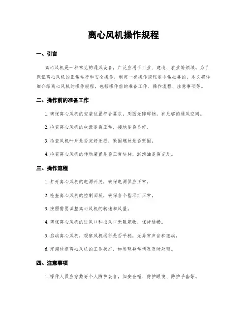
离心风机操作规程一、引言离心风机是一种常用的通风设备,广泛应用于工业、建筑、农业等领域。
为了确保离心风机的安全运行和有效工作,制定并遵守操作规程是至关重要的。
本文将详细介绍离心风机的操作规程,包括操作前的准备工作、操作步骤、注意事项以及紧急情况处理等方面。
二、操作前的准备工作1. 确保离心风机的工作场所安全,避免有易燃、易爆、腐蚀性气体等危险物质存在。
2. 检查离心风机的电源是否正常,电气线路是否接地良好。
3. 检查离心风机的机械部件是否完好,无松动、磨损等现象。
4. 确保离心风机周围无阻碍物,保持通风畅通。
三、操作步骤1. 打开离心风机的电源开关,确保电机正常启动。
2. 调整离心风机的转速,根据实际需要选择合适的转速档位。
3. 检查离心风机的进风口和出风口是否畅通,无堵塞物。
4. 根据需要调整离心风机的进风方向和出风方向。
5. 观察离心风机的运行情况,确保工作稳定、无异常噪音和振动。
6. 定期检查离心风机的润滑情况,保持轴承正常润滑。
四、注意事项1. 操作离心风机时,应注意个人安全,避免手指、衣物等被卷入风机内部。
2. 禁止在离心风机运行时进行维修、清洁等操作,必须先切断电源并等待其停止运行后再进行。
3. 禁止将易燃物品放置在离心风机附近,以免引发火灾。
4. 定期检查离心风机的电气线路,确保接地良好,避免电气故障。
5. 禁止超负荷运行离心风机,应根据实际需求合理调整转速。
6. 禁止随意更改离心风机的设计参数,必要时应咨询专业人士。
五、紧急情况处理1. 当离心风机发生异常噪音、振动等情况时,应立即切断电源并进行检修。
2. 当离心风机遇到突发故障无法正常运行时,应及时联系专业维修人员进行修理。
3. 在发生火灾等紧急情况时,应立即报警并采取适当的灭火措施,确保人员安全。
六、总结离心风机的操作规程是确保其安全运行和有效工作的重要保障。
通过遵守操作规程,可以降低事故风险,延长离心风机的使用寿命,提高工作效率。
离心风机操作规程一、引言离心风机是一种常见的通风设备,广泛应用于工业、建造、农业等领域。
为了保证离心风机的正常运行和安全操作,制定一套操作规程是非常必要的。
本文将详细介绍离心风机的操作规程,包括操作前的准备工作、操作流程、注意事项等。
二、操作前的准备工作1. 确保离心风机的安装位置符合要求,周围无障碍物,有足够的通风空间。
2. 检查离心风机的电源是否正常,接地是否良好。
3. 检查风机叶片是否完好无损,紧固螺丝是否坚固。
4. 检查离心风机的传动装置是否正常运转,润滑油是否充足。
三、操作流程1. 打开离心风机的电源开关,确保电源供应正常。
2. 检查离心风机的控制面板,确保各个指示灯正常。
3. 按照需要调整离心风机的转速和风量。
4. 确保离心风机的进风口和出风口无阻塞物,保持通畅。
5. 启动离心风机,观察风机运行是否平稳,无异常声音和振动。
6. 定期检查离心风机的工作状态,如发现异常情况及时处理。
四、注意事项1. 操作人员应穿戴好个人防护装备,如安全帽、防护眼镜、防护手套等。
2. 禁止将手或者其他物体伸入离心风机的进风口或者出风口。
3. 禁止在离心风机运行时进行维修和清洁操作,必须停机后方可进行。
4. 禁止使用未经授权的人员操作离心风机。
5. 定期对离心风机进行维护保养,清洁灰尘和杂物,检查传动装置的紧固情况。
6. 在离心风机运行过程中,如发现异常噪音、振动或者其他异常情况,应即将停机检查。
五、总结离心风机操作规程是确保离心风机正常运行和安全操作的重要保障。
操作人员应严格按照规程进行操作,确保自身安全和设备的正常运行。
同时,定期维护保养和检查离心风机,可以延长其使用寿命,提高工作效率。
通过合理的操作和维护,离心风机将为各行各业的生产和生活提供可靠的通风服务。
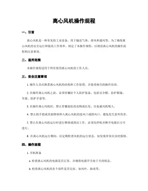
离心风机操作规程一、引言离心风机是一种常见的工业设备,用于输送气体、排风和通风等。
为了确保离心风机的安全运行和提高工作效率,制定了本操作规程,以规范离心风机的操作流程和注意事项。
二、适用范围本操作规程适用于所有使用离心风机的工作人员。
三、安全注意事项1. 操作人员应熟悉离心风机的结构和工作原理,并接受相关的操作培训。
2. 在操作离心风机之前,必须穿戴好个人防护装备,包括安全帽、防护眼镜、耳塞、防护手套等。
3. 在操作离心风机时,禁止穿戴宽松的衣物或长发,以免被风机吸入。
4. 禁止将手指或其他物体伸入离心风机的进风口或排风口,避免发生意外伤害。
5. 禁止在离心风机运行时进行维修或清洁工作,必须先停机并断开电源后方可进行。
6. 在离心风机运行期间,应定期检查风机的运行状态,如发现异常应及时报修。
四、操作流程1. 开机准备a. 检查离心风机的电源是否正常,并确保电源开关处于关闭状态。
b. 检查离心风机的各个部件是否完好,如风叶、轴承等。
c. 确保离心风机的进风口和排风口畅通无阻。
2. 启动离心风机a. 打开电源开关,离心风机开始供电。
b. 检查离心风机的运行方向是否正确,如果反向运行,应立即切断电源并更改接线。
c. 缓慢旋转离心风机的风叶,观察是否有异常声音或震动。
3. 调节风机转速a. 根据实际需求,使用调速器或变频器等设备调节离心风机的转速。
b. 在调节过程中,注意观察风机的运行状态,确保转速平稳。
4. 监控离心风机运行a. 定期检查离心风机的电流和电压是否正常,如有异常应及时处理。
b. 观察离心风机的运行噪音和振动是否超过正常范围,如有异常应及时检修。
c. 定期清洁离心风机的进风口和排风口,避免积尘影响风机的工作效率。
5. 关机操作a. 在停机前,应先将离心风机的转速调至最低档,然后再切断电源。
b. 关闭电源开关,确保离心风机停止供电。
c. 清理离心风机周围的工作区域,确保无杂物堆积。
五、紧急情况处理1. 在离心风机运行过程中,如发生异常噪音、异味等情况,应立即停机并通知相关人员进行检修。
目录1.风机的用途及适用范围 (1)2.风机的结构形式 (1)3.风机的安装、调整和试运转(分别为D式、F式) (2)4.风机的运行 (5)5.风机的维护 (6)6.风机成套供货范围(一台) (6)7.订货需知(需提供下列资料) (7)8.备件订货说明 (7)表一:经常或定期检查项目 (9)表二:运行时每3—6个月检查的项目 (9)表三:风机的主要故障及排除方法 (11)表四:轴承振动允许值 (12)附图I (13)附图II (14)附图III (15)附图IV (16)附图V (17)附图VI (18)本技术文件受法律保护,未经本公司同意,不得使用、复制、扩散或以其它方式提供给第三方。
1.风机的用途及适用范围该说明书适用于成都电力机械厂(CPMW)设计制造的D式(悬臂式)、F式(双支撑)离心风机的安装调试。
1.1 各系列风机适用于汽轮发电机组蒸汽锅炉的送、引、一次、二次、密封、排粉、增压风机等系统,也适用于矿井及其它工业的强制通风。
1.2 送、一次、二次、密封风机输送的介质为常温空气,其最高温度不超过80℃;引、增压风机输送介质为烟气,其最高温度不超过250℃;排粉风机输送的介质为含尘量不大于80 g/m3、最高温度不超过250℃的非腐蚀性气体。
1.3在引风机前须加装除尘装置,除尘效率不得低于99%,进入风机的烟气含尘量一般应小于200mg/m3。
2.风机的结构形式2.1 各系列离心风机由不同机号组成。
风机进出口角度分别为0°、45°、90°、135°、180°、225°共六种标准角度供选配,特殊进出口角度在订货时协商解决2.3 通风机叶轮的旋转方向可分为右旋和左旋两种,从电动机端看风机顺时针旋转为右旋,逆时针旋转为左旋。
2.4 各系列风机主要由叶轮、机壳、进气箱、集流器、调节门及转动组等部分组成。
2.4.1 常规风机叶轮为板式或机翼式叶片,采用Q345R钢板焊接而成。
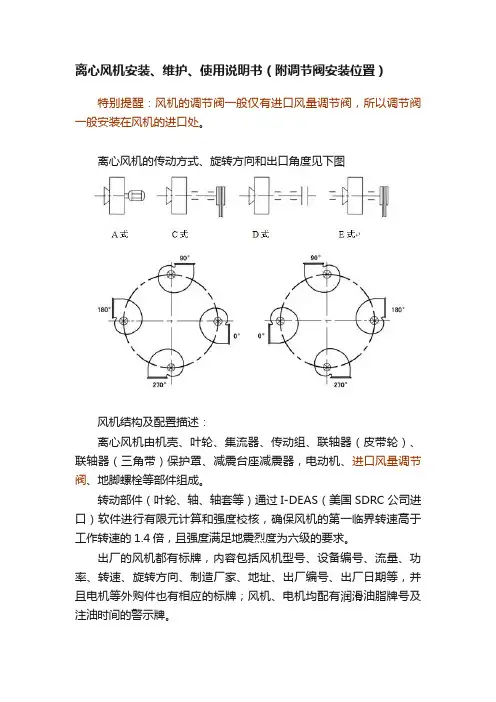
离心风机安装、维护、使用说明书(附调节阀安装位置)特别提醒:风机的调节阀一般仅有进口风量调节阀,所以调节阀一般安装在风机的进口处。
离心风机的传动方式、旋转方向和出口角度见下图风机结构及配置描述:离心风机由机壳、叶轮、集流器、传动组、联轴器(皮带轮)、联轴器(三角带)保护罩、减震台座减震器,电动机、进口风量调节阀、地脚螺栓等部件组成。
转动部件(叶轮、轴、轴套等)通过I-DEAS(美国SDRC公司进口)软件进行有限元计算和强度校核,确保风机的第一临界转速高于工作转速的1.4倍,且强度满足地震烈度为六级的要求。
出厂的风机都有标牌,内容包括风机型号、设备编号、流量、功率、转速、旋转方向、制造厂家、地址、出厂编号、出厂日期等,并且电机等外购件也有相应的标牌;风机、电机均配有润滑油脂牌号及注油时间的警示牌。
为了确保设备运行时的安全性,采用联轴器(三角带)传动的风机,配有可拆的保护罩,并保证外观美观。
风机各联接部分均采用PFF胶条密封,主轴穿过机壳部分采用迷宫式填料密封,确保气体不泄漏。
风机轴承采用SKF轴承,配套润滑油,为了确保轴承温升不超过40℃,轴承最高温度不超过70℃,对于介质温度高于80℃的风机采用冷却风扇冷却,对于介质温度高于180℃的风机采用冷却水冷却,带走大部份热量,确保轴承温度不会升得太高。
部件结构描述:1机壳:(1)为便于安装和维修,风机配有起吊吊环和观察检修口,便于对设备运转情况进行监控,便于维修和保养。
(2)大型风机机壳14号以上采用上、下剖分结构,方便了安装与维护。
(4)机壳侧板、蜗板通过I-DEAS(美国SDRC公司进口)软件进行有限元计算和强度校核,并用加强筋板有针对性的进行补强,确保机壳足够的刚度和强度。
2、叶轮:(1)叶轮均经过静、动平衡的校验,确保平衡精度等级小于G4.0级。
(2)叶轮的前盘、后盘、叶片采用激光切割下料,模具成型,机壳和叶轮为日本进口NAS数控焊接机器人自动焊接成型,并采用无损探伤检查,确保使用强度和性能稳定可靠。
离心风机操作规程引言概述:离心风机是一种常见的工业设备,用于输送空气、气体或粉尘等物质。
正确操作离心风机对于确保设备正常运行、延长设备寿命至关重要。
本文将详细介绍离心风机的操作规程,帮助操作人员正确操作设备,确保安全生产。
一、设备检查1.1 确保设备安全在操作离心风机之前,首先要确保设备周围没有杂物堆积,通风口没有被堵塞,以确保设备正常通风散热。
同时,检查设备的电源线是否完好,接地是否良好,以避免电气安全事故发生。
1.2 检查设备机械部件检查离心风机的机械部件,包括叶轮、轴承、传动装置等是否有异常磨损、松动或损坏情况,及时进行维修或更换,以确保设备正常运转。
1.3 检查设备控制系统检查离心风机的控制系统,包括启停按钮、调速器、安全保护装置等是否正常运作,确保设备在操作过程中能够及时响应操作指令,保障操作人员安全。
二、启动操作2.1 启动前准备在启动离心风机之前,应先打开设备的通风口,确保设备正常通风散热。
然后按照操作手册的要求检查设备各项参数是否符合要求,确认无误后方可启动设备。
2.2 启动离心风机按照操作手册的要求,依次启动离心风机的电源开关、启动按钮,观察设备是否正常启动,并逐步调整转速至设定值,确保设备正常运转。
2.3 监控设备运行情况在设备启动后,应及时监控设备的运行情况,包括电流、转速、温度等参数是否正常,如发现异常情况应及时停机检修,避免事故发生。
三、运行操作3.1 设备稳定运行在设备正常启动后,应保持设备稳定运行,避免频繁启停对设备造成损坏。
同时要确保设备在规定的工作范围内运行,避免超负荷运转。
3.2 定期检查设备定期检查离心风机的机械部件、电气部件和控制系统,发现问题及时处理,确保设备长期稳定运行。
3.3 注意安全操作在操作离心风机时,操作人员应注意安全操作规程,避免身体接触设备旋转部件,穿戴好防护装备,确保人身安全。
四、停机操作4.1 停机前准备在停机之前,应先将设备转速逐渐降低至零,然后关闭电源开关,确保设备停机前没有异常情况。
离心风机操作规程一、引言离心风机是一种常用的通风设备,广泛应用于工业生产、建筑物通风以及空调系统中。
为了确保离心风机的安全运行和有效使用,制定本操作规程,明确离心风机的操作流程和安全注意事项。
二、适用范围本操作规程适用于所有使用离心风机的工作人员,包括操作员、维护人员和相关管理人员。
三、安全注意事项1. 操作人员必须熟悉离心风机的结构、性能和操作要求,遵守相关的安全操作规定。
2. 在操作离心风机前,必须检查其周围环境是否安全,确保没有杂物、人员或其他障碍物。
3. 在操作离心风机前,必须检查电源是否正常,电气设备是否完好,确保操作安全。
4. 操作人员必须穿戴符合要求的个人防护装备,包括安全帽、防护眼镜、耳塞等。
5. 禁止在离心风机运行时进行任何维修、检修或调整操作,必须在停机状态下进行。
6. 禁止将手或其他物体伸入离心风机的进出口,以免发生危险。
7. 禁止在离心风机运行时随意更改设备参数或操作方式,必须经过相关授权人员批准。
8. 在离心风机运行过程中,如发现异常情况或异常噪音,应立即停机检查,并报告相关人员。
四、离心风机操作流程1. 准备工作a. 确保离心风机周围环境安全,清除杂物和障碍物。
b. 检查电源是否正常,电气设备是否完好。
c. 穿戴个人防护装备。
2. 启动离心风机a. 检查离心风机的开关、按钮和仪表是否正常。
b. 打开电源,按照启动顺序逐步启动离心风机。
c. 观察离心风机的运行状态,确保无异常情况。
3. 调整离心风机参数a. 根据实际需要,调整离心风机的转速、风量和风压等参数。
b. 注意不要超过离心风机的额定工作范围,以免损坏设备或引发安全事故。
4. 监控离心风机运行a. 定期观察离心风机的运行状态,包括噪音、振动、温度等指标。
b. 如发现异常情况,应立即停机检查,并报告相关人员。
5. 停止离心风机a. 在停止离心风机前,先将负载卸掉,确保安全停机。
b. 依次关闭离心风机的电源和操作开关,确保设备停止运行。
离心风机操作规程一、引言离心风机是一种常用的通风设备,广泛应用于工业、商业和家庭等领域。
为了确保离心风机的安全运行和有效使用,制定了本操作规程。
本规程旨在指导操作人员正确操作离心风机,提高工作效率,确保人员安全。
二、适用范围本操作规程适用于所有使用离心风机的操作人员。
三、操作人员的基本要求1. 操作人员应具备相关的技术知识和操作经验,了解离心风机的结构、工作原理和安全注意事项。
2. 操作人员应经过专业培训,并持有相关的操作证书。
3. 操作人员应严格遵守本操作规程,遵守相关的安全操作规定。
四、离心风机的准备工作1. 操作人员应检查离心风机的外观是否完好,有无损坏或松动的部件。
2. 操作人员应确保离心风机的供电电源符合要求,并进行必要的接地。
3. 操作人员应清理离心风机周围的杂物,确保通风畅通。
五、离心风机的操作步骤1. 操作人员应按照离心风机的启动顺序,依次打开电源开关、控制开关和风机开关。
2. 操作人员应注意观察离心风机的运行情况,确保无异常噪音、振动或漏风现象。
3. 操作人员应根据实际需要调节离心风机的转速,通过控制面板或调速装置进行调节。
4. 操作人员应定期检查离心风机的工作状态,包括温度、压力、电流等参数,确保正常运行。
六、离心风机的停机步骤1. 操作人员应先关闭离心风机的风机开关,待风机停止运行后再关闭控制开关和电源开关。
2. 操作人员应检查离心风机的周围环境,清理杂物,确保安全。
3. 操作人员应记录离心风机的运行时间、故障情况和维护记录,以便后续的维护和检修工作。
七、离心风机的维护保养1. 操作人员应定期对离心风机进行清洁,包括清理风机叶轮、滤网和排风口等部件。
2. 操作人员应定期检查离心风机的润滑油,根据需要添加或更换。
3. 操作人员应定期检查离心风机的电机和电气连接,确保正常工作。
4. 操作人员应定期检查离心风机的轴承和密封件,如有损坏应及时更换。
八、应急处理措施1. 在离心风机发生故障或异常情况时,操作人员应立即停机,并采取相应的应急处理措施。
Centrifugal FansDecember20222Greenheck's single-width centrifugal fans are designed to provide efficient and reliable operation for commercial and industrial applications. Our products are manufactured with state-of-the-art laser, forming, spinning and welding equipment, and undergo quality control testing to ensure a trouble-free start-up.Benefits of Greenheck Centrifugal Products• AMCA licensed performance and UL Listed• Ease of selection using Greenheck’s eCAPS ® or CAPS ® software selection tools • Tiered product portfolio offering the best value fan for any given application • AutoCAD ® and Revit ® models available for download • Quick Build and Fast Pass expedited shipping programs • Factory tested prior to shipmentCentrifugal FansUL/cUL 705 Listed Power Ventilator UL/cUL File E40001UL/cUL 762 Power Ventilators for Restaurant Exhaust Appliances UL/cUL File MH11745UL/cUL Power Ventilator for Smoke Control SystemsUL/cUL File MH17511Certified data may be found in Greenheck’s Computer Aided Product Selection program (CAPS)CertificationsManufactured in the USAModel USF fans are built in one of twomanufacturing locations, Schofield, WI and Shelby, NC. Multiple manufacturing locations enable us to build fans and get them to you, our customer, faster.Quick Build AvailabilitySelect model USF fan configurations are available in as little as 5 days on our Quick Build program.AirPerformance AMCA Sizes Wheel A1, A2Sound and Air 18 - 73AF B1, B6Sound and Air4 - 73BI B2, B7Air 4 - 24BI B3Air 4 - 18BI B4Air 27 - 49BI B5Air 6 - 10BI F1, F3Air 9 - 24FC F2Air6 - 10FC3Greenheck’s centrifugal products are designed to handle a variety of commercial and industrial applications:• General supply, return or exhaust systems• Emergency smoke exhaust (buildings, car parks, etc.)• Restaurant grease exhaust • Stairwell pressurization •Process heat exhaust• Filter houses and dust collectors • Built-up or custom air handlers • Spark-resistant fume exhaust • Corrosive fume exhaust •Grain dryingApplicationsEmergency Smoke (UL/cUL Listed):Atriums, libraries, multistory buildingsSelect Greenheck centrifugal fans are UL/cUL Listed for Power Ventilators for Smoke Control Systems. Fans can be installed for dual application use or as a dedicated emergency system, with the primary function of the fan being general air movement, but built to withstand operation seen in emergency smoke situations. The UL Listing indicates the model is designed and tested to exhaust heat and smoke in an emergency situation.The emergency high temperature option is suitable for the following temperatures:Operating TemperatureTime Duration500ºF (260ºC) 4 hours 572ºF (300ºC) 2 hours 752ºF (400ºC) 2 hours 1000ºF (538ºC)15 minutesHigh Temperature Process Exhaust:Kilns, Dryers, FurnacesDesigned for applications involving elevated temperatures above 250°F (121°C) continuously for extended periods of time. Material and arrangement choices are limited to components suitable for this application and located to minimize effects. Fans manufactured with a high temperature process package include hightemperature shaft seal, heat slinger, high temperature fan bearing grease, and high temperature coating on steel fans. Heat slinger dissipates heat being transferred down the fan shaft preventing bearing grease evaporation. Applications up to 1000°F can be handled with the use of stainless steel materials.Restaurant Grease Exhaust (UL/cUL 762 Listed):RestaurantsThe centrifugal scroll fans are designed for high pressure restaurant grease exhaust applications. Either Permalock™ or welded housing are available with UL/cUL Listing of Power Ventilators for Restaurant Exhaust Appliances. The welded housing is suitable for indoor or outdoor mounting locations, whereas the Permalock™ housing is suitable for outdoor kitchen ventilation installations. Listing tests exceed duct temperatures of 400°F (204°C) continuous operation. UL/cUL 762 selections require a drain connectionand access door for cleaning.UL/cUL 705 Listed Power Ventilator UL/cUL File E40001UL/cUL 762 Power Ventilators for Restaurant Exhaust Appliances UL/cUL File MH11745UL/cUL Power Ventilator for Smoke Control Systems UL/cUL File MH175114Construction OptionsAlternative MaterialsGreenheck offers centrifugal fans in aluminum or stainless steel construction as an alternative to coatedsteel. Aluminum construction provides advantages for applications with high moisture and various chemicals. Aluminum also reduces the weight of the fan if there are structural concerns. Stainless steel (316L) construction is used for environments subject to continuous high heat up to 1000ºF (538ºC) or severe corrosives. Bothaluminum or stainless steel construction can be applied to the entire fan (housing, wheel, inlet cone and drive frame) or the airstream components (housing, wheel and inlet cone) only.Spark-Resistant ConstructionGreenheck centrifugal fans are available with spark-resistant designs suitable for applications that involveflammable particles, fumes or vapors. Spark-resistant construction options adhere to guidelines defined withinAMCA Standard 99-0401-86.Spark AAll parts in contact with the airstream are constructed of nonferrous material (usually aluminum).Spark BThe fan wheel is constructed of a nonferrous material (usually aluminum). A nonferrous (aluminum) rub ring surrounds the fan shaft where it passes through the fan housing.Spark CThe inlet cone is constructed of nonferrousmaterial (usually aluminum). A nonferrous (aluminum) rub ring surrounds the fan shaft where it passes through the fan housing.Permalock ™ HousingsPermalock™ housings use a mechanically fastened seam instead of welding. This airtight and watertight housing construction uses the same structural support as all welded housings. Permalock™ construction is an excellent value engineering option for applications up to 8.5 in. wg (2.1 kPa).Welded HousingsOptional on Class 0, I, II and standard on larger fan sizes, centrifugal fans are manufactured with heavy-gauge, welded housing construction. All welded construction is common for industrial applications and issuitable for pressures up to 22 in. wg (5.5 kPa).Backward-Inclined (BI)Airfoil (AF)Forward-Curved (FC)Wheel TypeApplication General purpose, clean air or severe environments Clean air or fume exhaust Clean air Temperature Up to 1000ºF (538ºC)Up to 500ºF (260ºC)Up to 180ºF (82ºC)ConstructionSteel Aluminum316 Stainless SteelSteel AluminumSteel AluminumWheelsGreenheck centrifugal fans have multiple wheel options. All wheels are statically and dynamically balanced to grade G6.3 per ANSI S2.19.Wheel5Construction OptionsPerformance TestedWhen selecting a powder coating finish for heavy-gauge welded steel fans, critical information such as environment, moisture, exposure, abrasives, and chemicals should be considered.Powder coatings are the best choice for most extreme applications. Major advantages over most vendor-applied liquid coatings include:•Superior finish with uniform coverage and thickness • A better coating provides better protection • The process is environmentally friendly • Unequaled valueEnvironmentsC L E A N A I RC O A S T A LC H E M I C A L *E X T R E M E W E A T H E RA B R A S I V EP ART IC L E S S U N -U VCoatingsColor Coating SpecificationsO n e C o a t P r o c e s sPermatector™Standard coating for steel products in both indoor and outdoor applicationsC o n c r e t e G r e y R A L 7023Thickness: 2.0 - 3.0 mils Polyester urethane powder coatingXXHi-Pro PolyesterFormulated for exterior durability,color and gloss retention. Excellent for chemical applications.Thickness: 2.0 - 3.0 mils High performance polyester urethane powder coatingX XXT w o C o a t P r o c e s sHi-Pro-ZT wo-coat powder paint coating isresistant to saltwater, chemical fumes and moisture in corrosive environmentsThickness: 4.0 - 6.0 milsHi-Pro Polyester topcoat with epoxy basecoatX X X X XXTwo-Coat AdvantageFor corrosive environments, use Greenheck’s Hi-Pro-Z two-coat coating technology. Test data demonstratesour two-coat paint system offers four times the corrosion resistance of other coatings commonly available within the fan industry.4-6 mils TotalEpoxy PrimerTopcoat Base SteelAdvancedSurface PreparationProtective CoatingsGreenheck offers a wide variety of protective coatings suitable for corrosive applications. All coatings are electrostatically-applied baked powders that offer a durable, long lasting finish. For more information on ourcomplete offering of coatings, visit and navigate to Resources/Library/Application-Articles. Search for Straight Talk on Protective and Aesthetic Coatings for Commercial/Industrial Fans .Chemical Resistance RatingsChemicalBleachSulfuric Acid(10%)HCI (10%)MEK Chlorine (0.1%)NaOH (20%)Permatector 01220—Hi-Pro Polyester 00010—Hi-Pro-Z11RATING DESCRIPTIONS0 - No effect1- Slight change in gloss or color2 - Surface etching, severe staining, but film integrity remains3 - S ignificant pitting, cratering, swelling, or erosion with obvious surface deterioration6Premium BearingsBelt drive centrifugal products are manufactured with “Air Handling Quality”self-aligning ball or roller pillow block bearings. All bearings include zerk fittings for relubrication and are selected for a basic rating fatigue life of L 10 in excess of 40,000 hours (L 50 at 200,000 hrs.) at the maximum RPM for the selected pressure class.L 10 life implies 90% reliability or 10% failure rate after the stated hours.L 50 life implies 50% reliability or 50% failure rate after the stated hours.The USF offers multiple levels of bearing sets allowing for the proper balance between service intervals and initial cost. Estimated bearing life can be supplied once a fan is fully configured.Construction OptionsVibration AnalysisAll centrifugal wheels undergo a computerized balance analysis to a grade of G6.3. In addition, centrifugal products offer an optional complete mechanical vibration test after assembly. Our custom data acquisition system uses tri-axial accelerometers to measure the vibration in three planes at the design operating speed. A permanent record for each fan’s performance is kept on file and is available upon request.The standard “filter-in” vibration levels attained meet the requirements of Fan Application BV-3 as defined in AMCA Standard 204-05 “Balance Quality and Vibration Levels for Fans”. Consult factory if more stringent vibration levels are necessary.Drive TypeFilter-In Vibration Limit (Rigidly Mounted)Belt 0.15 in/sec-pk Direct Arrg. 40.08 in/sec-pk Direct Arrg. 80.15 in/sec-pkCopies of these signatures are kept on file and are available upon request.7ConfigurationsArrangement 1 — Belt Drive• Bearings are mounted out of the airstream • Unlimited motor size• Requires an isolation base (by factory) or structural pad to mount the fan and motor • Available with motor cover• Suitable for high temperatures or contaminated airIsolation BaseFanZYX WMotor position and fan rotation are determined from drive sideIsolation BaseSingle Width Fan Z Y X WMotor position and fan rotation aredetermined from drive sideArrangement 4 — Direct Drive • Available with partial width wheel and housing modifications for specific performance • Recommended for higher horsepower applications in lieu of belt drive • Limited to standard motor speeds, but are available with variable frequency drive compatible motors • Provides compact design with low maintenance • Available with motor cover Arrangement 8 — Direct Drive• Available with partial width wheel and housing modificationsfor specific performance• Recommended for higher horsepower applications in lieuof belt drive • Limited to standard motor speeds, but are available with variable frequency drive compatible motors • Bearings located out of the airstream • Suitable for high temperatures or contaminated air• Available with motor cover, belt guard Arrangement 10 — Belt Drive• Recommended as first choice configuration for belt drive applications• Most compact belt drive arrangement• Bearings are mounted out of the airstream • Motor is mounted beneath the drive frame• Available with a weatherhood to cover motor, drives and bearings• Moderate dirt and heat toleranceIsolation BaseFanZYX WMotor position and fan rotation aredetermined from drive sideIsolation BaseSingle WidthFanZYXWMotor position and fan rotation are determined from drive side8Discharge Positions and Rotatable HousingsRotation and discharge is always determined from the drive side of the fan.ConfigurationsCW THCCW TH CW DBCCW DB CW BHCCW BHCW TAUCCW TAU CW UBCCW UB CW BAUCCW BAU Class of ConstructionAMCA defines fan class based on minimum outlet velocities and pressures a fan must be capable to produce. Fan classes are designated as 0, I, II, or III. As the fan class increases, the outlet velocity and pressure requirements increase as defined in AMCA Standard 99. As the outlet velocity and pressures increase, the fan construction (material gauge, shaft diameter, motor size, etc.) must also change to physically accommodate the faster RPMs required.Centrifugal products are available in Class 0, I, II, or III, with Class 0 having the lowest maximum fan RPM and Class III having the highest maximum fan RPM.A typical fan curve is shown with shaded classlimits. For specific certified fan data, please consult Greenheck’s Computer Aided Product Selection program, CAPS ®.Class 0Class I Class II Class IIIS t a t i c P r e s s u r e (i n . w g )S t a t i c P r e s s u r e (P a x 100)Volume (cfm x 1000)3Volume (m /hr x 1000)204060802040D ON OT S E L E C T L E F T O F T HI S S Y S T E M C U R V E051015RPM BHP % WOVDensity 0.075 lb/ft Density 1.2 kg/m 750360090010511200137115005 7½ 7½ 101520172725403016005060751009AccessoriesVibration Isolators and Isolation BasesGreenheck offers a complete package of vibration isolators, isolation bases and inertia bases to simplify field assembly and reduce transmitted vibrations.Refer to the catalog on /Resources/Library/Literature. Search for Mounting Bases and Vibration Isolation .Mounting TypesIsolation base with height saving bracketsDirect MountNo base required, isolators are attached directly to equipment. Direct isolation can be used if equipment is unitary and rigid without the use of additional support. This option is not available on arrangement 1 or 8 USF fans.Isolation BaseIsolation bases consist of formed steel members welded into a rigid one-piece base. A motor slide base is included where applicable. Bases are required for all arrangement 1 and 8 fans with mounted motors. Isolation bases are available without isolators, with rubber mounts or with spring mounts. All formed steel bases with spring mounts incorporate height saving brackets.Isolator TypesRubber MountNeoprene mountings consist of a steel top plate and base plate completely embedded in colored (oil-resistant) neoprene for easy identification of capacity. Neoprene mountings are furnished with a tapped hole in the center. This enables the equipment to be bolted securely to the rubber mount.Free-Standing Open Spring MountFree-standing spring isolators are unhoused laterally stable steel springs. These isolators are for indoor use only. Free-standing open spring mounted isolators provide a minimum horizontal stiffness of 0.8 times the rated vertical stiffness and provide an additional 50% overload capacity. They are equipped with a top-mounted adjusting bolt and an acoustical non-skid base. Springs are color-coded or identified to indicate load capacity.Restrained Spring MountRestrained spring isolators consist of laterally stable, free-standing springs assembled into a steel housing. These assemblies are designed for vertical and horizontal motion restraint. Springs provide 50% overload capacity and are color-coded or identified to indicate load capacity. Restrained spring mounts are recommended for equipment subject to wind-loading or large torquing forces. They are also used for equipment subject to large weight changes such as swing-out fans.RestrainedNeopreneFree StandingAccessoriesAccess DoorBolted or hinged access doors provide access for cleaning or inspection.Backdraft DamperBackdraft dampers are available in galvanized or aluminum construction and include counterweights for tight closure when the fan is de-energized.Belt GuardBelt guards are designed to allow easy access to the belts and pulleys for service. All belt guards include tachometer openings to monitor the fan speed as well as an access panel for testing belt tension. Belt guards meet OSHA guidelines.Disconnect SwitchGreenheck offers a wide selection of NEMA rated fusible or non-fusible disconnect switches. Switches can be factory mounted or shipped loose forfield installation.DrainA one-inch (25 mm) threaded drain connection is located at the bottom of the fan housing to drain water that may accumulate. A simple, nonthreaded hole is also available as an economy option. Extended Lubrication LinesSingle-width fans are available with flexible nylonor copper tubing extending from the bearings to conveniently located grease fittings mounted on the fan pedestal (or on the exterior of the weatherhood if a weatherhood is supplied).Grease ContainmentGrease trap is designed to collect grease residue to avoid drainage onto roof surface. Grease traps ship loose for field installation.Heat SlingerThe heat slinger is an aluminum cooling disc mounted on the fan shaft between the inboard bearing and the blower housing to dissipate heat conducted along the fan shaft.Inlet Companion FlangePunched companion inlet flanges are available on single-width fans.Inlet and Outlet FlangesOptional inlet flanges on single-width fans are pre-punched and welded to the inlet collar. Punched outlet flanges are standard on fan sizes 33-73.Inlet and Outlet GuardsRemovable inlet and outlet guards provide protection for personnel and equipment in non-ducted installations. Inlet and outlet guards meet OSHA guidelines.Motor Cover (Arrg. 1, 4, or 8)A weatherproof motor cover shields the motor components from dust, dirt and moisture for outdoor installations.Shaft Guard (Arrg. 1 or 8)Shaft guards are designed to cover shafts and bearings. Extended lube lines are optional for bearing lubrication without removal of the guard. Shaft guards meet OSHA guidelines.Shaft SealA shaft seal helps contain the airstream inside the fan for operation at high temperatures or for exhausting contaminated air.Stainless Steel ShaftStainless steel fan shafts are available for applications where standard carbon steel shafts may exhibit excessive corrosion or heat stress.Sure-Aire™Noninvasive flow monitoring system capable of capturing accuracy within 3% and available with or without electronics. Clean air applications only. Weatherhood (Arrg. 10)Vented steel weatherhoods protect the motor and drive components from rain, moisture, dust, and dirt. Weatherhoods meet OSHA guidelines and are easily removed for service access.Vari-Green® MotorGreenheck’s electronically commutated (EC)Vari-Green motor combines motor technology, controllability and energy efficiency into a single,low-maintenance unit.Volume Control:Volume Control DamperControl dampers are available ingalvanized or aluminum. Actuatoroptions include manual quadrantor electric.VFD and Rated MotorVariable frequency drives (VFDs) change the frequency of the input power to the motor, which results in changing the motor’s speed. Changing the speedof the fan provides the greatest potential for energy savings at partial loads.1011Motor and ControlsVari-Green ® MotorElectronically commutated (EC) Vari-Green ® (VG) motor combinestechnology, controllability, and energy efficiency into a single, low-maintenance package that is changing the way the industry designs,specifies and operates air movement equipment.Single-phase VG motors are available in sizesranging from 1/4 to 1 hp.Three-phase VG motors are available in sizes ranging from 1 to 10 hp in both 1200 and 1800 rpm.Vari-Green ControlsAvailable on all control packages (both VG and Induction).• Hands/Off/Auto (HOA)• Remote Dial• Touch Remote• Constant Pressure• IAQ – Temperature/Humidity•IAQ – VOCSingle and three-phase induction motors are availablein many configurations. A VFD control box with VG HOAinterface is available from the factory as ship loose ormounted and wired up to 30 hp.P.O. Box 410 • Schofield, WI 54476-0410 • Phone (715) 359-6171 • As a result of our commitment to continuous improvement, Greenheck reserves the right to changespecifications without notice.Product warranties can be found online at , either on the specific product page or inthe literature section of the website at /Resources/Library/Literature.Our Commitment00.CVI.1033 R6 12-2022Copyright © 2022 Greenheck Fan Corp.Greenheck’s Centrifugal Product OfferingGreenheck’s tiered model approach gives you flexibility in size, performance andconstruction matching the appropriate model to your application. Our centrifugalproduct line offers a variety of options in construction features, materials andperformance by model.Enjoy Greenheck’s extraordinary service, before, during and after the sale.Greenheck offers added value to our wide selection of top performing, energy-efficient products by providing several unique Greenheck service programs.• O ur Quick Delivery Program ensures shipment of our in-stock products within 24 hours of placing your order. Our Quick Build made-to-order products can be produced in 1-3-5-10-15-20 or 25-day production cycles, depending upon their complexity.• G reenheck’s free Computer Aided Product Selection program (CAPS ®), rated by many as the best in the industry, helps you conveniently and efficiently select the right products for the challenge at hand.• G reenheck continues to take an industry-wide leadership position to affect positive global sustainability. We believe that providing education on products we offer contributes to reducing energy consumption and improving healthier indoor environments.• O ur 3D service allows you to download, at no charge, easy-to-use AutoDesk ® Revit ® 3D drawings for many of our ventilation products.Find out more about these special Greenheck services at • Backward-inclined, forward-curved or airfoil wheel options• Class 0-III pressure ratings• Permalock™, fully welded or Quad-Split scroll designs• Belt or direct drive configurations• Galvanized, coated steel, aluminum or stainless construction materials• Spark-resistant or high temperature packages• Variable Frequency Drive (VFD) and Vari-Green ® controlsCentrifugal Fans。
目录1.风机的用途及适用范围 (1)2.风机的结构形式 (1)3.风机的安装、调整和试运转(分别为D式、F式) (2)4.风机的运行 (5)5.风机的维护 (6)6.风机成套供货范围(一台) (6)7.订货需知(需提供下列资料) (7)8.备件订货说明 (7)表一:经常或定期检查项目 (9)表二:运行时每3—6个月检查的项目 (9)表三:风机的主要故障及排除方法 (11)表四:轴承振动允许值 (12)附图I (14)附图II (16)附图III (18)附图IV (20)附图V (22)附图VI (24)本技术文件受法律保护,未经本公司同意,不得使用、复制、扩散或以其它方式提供给第三方。
心式通风机使用说明书1.风机的用途及适用范围该说明书适用于成都电力机械厂(CPMW)设计制造的D式(悬臂式)、F式(双支撑)离心风机的安装调试。
1.1 各系列风机适用于汽轮发电机组蒸汽锅炉的送、引、一次、二次、密封、排粉、增压风机等系统,也适用于矿井及其它工业的强制通风。
1.2 送、一次、二次、密封风机输送的介质为常温空气,其最高温度不超过80℃;引、增压风机输送介质为烟气,其最高温度不超过250℃;排粉风机输送的介质为含尘量不大于80 g/m3、最高温度不超过250℃的非腐蚀性气体。
1.3在引风机前须加装除尘装置,除尘效率不得低于99%,进入风机的烟气含尘量一般应小于200mg/m3。
2.风机的结构形式2.1 各系列离心风机由不同机号组成。
风机进出口角度分别为0°、45°、90°、135°、180°、225°共六种标准角度供选配,特殊进出口角度在订货时协商解决2.3 通风机叶轮的旋转方向可分为右旋和左旋两种,从电动机端看风机顺时针旋转为右旋,逆时针旋转为左旋。
2.4 各系列风机主要由叶轮、机壳、进气箱、集流器、调节门及转动组等部分组成。
2.4.1 常规风机叶轮为板式或机翼式叶片,采用Q345R钢板焊接而成。
RAEETS®高速直联离心风机使用说明书(型号:RAETTS--050)东莞市锐天机电科技有限公司目录一、产品主要结构.....................................二、风机机组安装.....................................三、水冷系统的安装................................四、电路控制柜................................................五、操作与使用........................................一、产品主要结构1、风机机组本体结构及特点简介风机主要有进风口、过滤器、蜗壳、叶轮、电机转子、电机定子、底座组等成。
1.1叶轮专用叶轮,经特殊材质精加工而成,均经过严格的无损伤检查,并且叶轮经过高精密动平衡校正处理。
为高速平稳运行提供可靠保证。
1.2高速电机高速电机两端端盖处设有检测轴承温度的铂热电阻探头(PT100),当接入电控系统联网时会显示电机前后轴承温度。
二、风机机组安装整个风机机组由风机、水冷系统、电柜三部分组成。
水冷系统和风机为单独整套一体式,组装时只需将水冷系统进出水管连接即可,组装风机时注意风机水平安装。
三、水冷系统的安装水冷系统包括水箱、一个250W水循环泵、一个散热风扇三部分组成。
水冷系统为整体式,不用单独安装,连接时进出水管和风机连接即可,并入控制系统。
要注意的是:每周定期检查水箱的水容量,水箱一旁有液位视镜。
四、电路控制柜安装位置:在风机附近安装牢固可靠,电路控制柜是用来监测、控制、调节、保护风机机组;整套风机机组正常运行的可靠保证。
控制电柜使用条件:本产品电源为三相四线制,额定电压380V,50HZ。
本产品在下列条件下能可靠工作:周围空气温度最高不超过+45℃,最低不低于-10℃,且通风良好的地方相对湿度≦85RH,不触及水、油及因温度变化凝结露水的地方无腐蚀性气体、可燃性气体,无灰尘、铁粉的地方无振动和冲击的地方,无强电场,无强磁场的地方电柜电路图:五、操作和使用无论是新安装或是检修后重新安装的机组,在正式投入负荷运行前都必须进行试运转。
离心通风机使用说明书宜兴市华电环保设备一、用途4-72型离心通风机作为一般工厂及大建筑物的室通风换气,即可用作输入气体,也可用作输出气体。
空气和其它不自燃、对人体无害的、对钢铁材料无腐蚀性的气体。
气体不许有粘性物质,所含的尘土及硬质颗粒不大于150mg/m3。
气体的温度:不超过80℃。
4-72型离心通风机在我国是使用最早的风机,然而也是使用最普通的风机,从高层建筑到地下铁道,从锅炉鼓风到厂房换气,4-72型风机随处可见。
二、型式从电机一侧正视,叶轮顺时针旋转者称右旋风机,以“右”表示;叶轮逆进针旋转者称左旋风机,以“左”表示。
风机的出口位置,以机壳的出风口角度表示。
4-72型风机№2.8~6出厂时均做成一种型式,使用单位根据要求再安装成所需要的位置,订货时不需注明。
其中№2.8出风口位置调整围是0°~255°,间隔是45°;№16、20出风口位置制成固定的三种0°、90°、180°,不能调整,订货时需注明。
风机的传动方式有A、B、C、D四种:4-72型风机中,№2.8~6采用A式传动,№8~12采用C、D式传动,№16~20采用B式传动。
三、结构4-72型风机中№2.8~6主要由叶轮、机壳、进风口、电机等部分组成。
№8~20除具有上述部分外,还有传动部分。
(1)叶轮:由10个后倾机翼型叶片、曲线型前盘和平板后盘组成,用钢板制造,并经动、静平衡校正,空气性能良好,效率高,运转平稳。
(2)机壳:做成二种不同型式。
其中№2.8~12机壳作成整体,不能拆开,№16~20的机壳制成三开式,除沿中分水平面分为两半外,上半部再沿中心线垂直分为两半,用螺栓连接。
(3)进风口:制成整体,装于风机一侧,与轴向平行的截面为曲线开关作用是能使气流顺畅时入叶轮,且损失较小。
(4)传动:由主轴、轴承箱、流动轴承、皮带轮或联轴器组成。
四、性能与选择本样本只给出№10样机的无因次性能和曲线,由性能和曲线计算№10以上风机的有因次性能参数。
离心通风机使用说明书宜兴市华电环保设备有限公司一、用途4-72型离心通风机作为一般工厂及大建筑物的室内通风换气,即可用作输入气体,也可用作输出气体。
空气和其它不自燃、对人体无害的、对钢铁材料无腐蚀性的气体。
气体内不许有粘性物质,所含的尘土及硬质颗粒不大于150mg/m3。
气体的温度:不超过80℃。
4-72型离心通风机在我国是使用最早的风机,然而也是使用最普通的风机,从高层建筑到地下铁道,从锅炉鼓风到厂房换气,4-72型风机随处可见。
二、型式从电机一侧正视,叶轮顺时针旋转者称右旋风机,以“右”表示;叶轮逆进针旋转者称左旋风机,以“左”表示。
风机的出口位置,以机壳的出风口角度表示。
4-72型风机№~6出厂时均做成一种型式,使用单位根据要求再安装成所需要的位置,订货时不需注明。
其中№出风口位置调整范围是0°~255°,间隔是45°;№16、20出风口位置制成固定的三种0°、90°、180°,不能调整,订货时需注明。
风机的传动方式有A、B、C、D四种:4-72型风机中,№~6采用A式传动,№8~12采用C、D式传动,№16~20采用B式传动。
三、结构4-72型风机中№~6主要由叶轮、机壳、进风口、电机等部分组成。
№8~20除具有上述部分外,还有传动部分。
(1)叶轮:由10个后倾机翼型叶片、曲线型前盘和平板后盘组成,用钢板制造,并经动、静平衡校正,空气性能良好,效率高,运转平稳。
(2)机壳:做成二种不同型式。
其中№~12机壳作成整体,不能拆开,№16~20的机壳制成三开式,除沿中分水平面分为两半外,上半部再沿中心线垂直分为两半,用螺栓连接。
(3)进风口:制成整体,装于风机一侧,与轴向平行的截面为曲线开关作用是能使气流顺畅时入叶轮,且损失较小。
(4)传动:由主轴、轴承箱、流动轴承、皮带轮或联轴器组成。
四、性能与选择本样本只给出№10样机的无因次性能和曲线,由性能和曲线计算№10以上风机的有因次性能参数。