MSP430X43X1中文资料
- 格式:pdf
- 大小:1.16 MB
- 文档页数:73
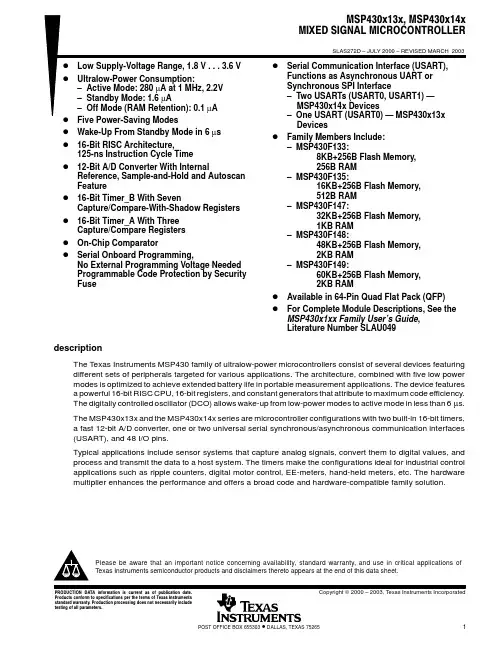
D Wake-Up From Standby Mode in Less Than 6 μsD 16-Bit RISC Architecture,125-ns Instruction Cycle Time D 12-Bit A/D Converter With Internal Reference, Sample-and-Hold and Autoscan FeatureD 16-Bit Timer_B With Three † or Seven ‡Capture/Compare-With-Shadow Registers D 16-Bit Timer_A With Three Capture/Compare Registers D On-Chip ComparatorDSerial Communication Interface (USART),Select Asynchronous UART or Synchronous SPI by Software:− Two USARTs (USART0, USART1) —MSP430x44x Devices − One USART (USART0) — MSP430x43x(1) Devices D Brownout DetectorDSupply Voltage Supervisor/Monitor With Programmable Level DetectionD Bootstrap LoaderDFamily Members Include:− MSP430F435, MSP430F4351§:16KB+256B Flash Memory,512B RAM− MSP430F436, MSP430F4361§:24KB+256B Flash Memory,1KB RAM− MSP430F437, MSP430F4371§:32KB+256B Flash Memory,1KB RAM− MSP430F447:32KB+256B Flash Memory,1KB RAM− MSP430F448:48KB+256B Flash Memory,2KB RAM− MSP430F449:60KB+256B Flash Memory,2KB RAMDFor Complete Module Descriptions, See The MSP430x4xx Family User’s Guide ,Literature Number SLAU056†’F435, ’F436, and ’F437 devices‡ ’F447, ’F448, and ’F449 devices§ The MSP430F43x1 devices are identical to the MSP430F43xdevices with the exception that the ADC12 module is not implemented.descriptionThe T exas Instruments MSP430 family of ultralow power microcontrollers consists of several devices featuring different sets of peripherals targeted for various applications. The architecture, combined with five low-power modes, is optimized to achieve extended battery life in portable measurement applications. The device features a powerful 16-bit RISC CPU, 16-bit registers, and constant generators that contribute to maximum code efficiency. The digitally controlled oscillator (DCO) allows wake-up from low-power modes to active mode in less than 6 μs.This integrated circuit can be damaged by ESD. Texas Instruments recommends that all integrated circuits be handled with appropriate precautions. Failure to observe proper handling and installation procedures can cause damage. ESD damage can range from subtle performance degradation to complete device failure. Precision integrated circuits may be more susceptible to damage because very small parametric changes could cause the device not to meet its published specifications. These devices have limited built-in ESD protection.PRODUCTION DATA nformat on s current as of publ cat on date.Products conform to specifications per the terms of Texas Instruments standard warranty. Production processing does not necessarily include testing of all parameters.Please be aware that an important notice concerning availability, standard warranty, and use in critical applications of Texas Instruments semiconductor products and disclaimers thereto appears at the end of this data sheet.SLAS344F − JANUARY 2002 − REVISED MAY 2007description (continued)The MSP430x43x(1) and the MSP430x44x series are microcontroller configurations with two built-in 16-bit timers, a fast 12-bit A/D converter (not implemented on the MSP430F43x1 devices), one or two universal serial synchronous/asynchronous communication interfaces (USART), 48 I/O pins, and a liquid crystal driver (LCD) with up to 160 segments.Typical applications include sensor systems that capture analog signals, convert them to digital values, and process and transmit the data to a host system, or process this data and display it on a LCD panel. The timers make the configurations ideal for industrial control applications such as ripple counters, digital motor control, EE-meters, hand-held meters, etc. The hardware multiplier enhances the performance and offers a broad code and hardware-compatible family solution.AVAILABLE OPTIONSPACKAGED DEVICEST A PLASTIC 80-PIN QFP(PN)PLASTIC 100-PIN QFP(PZ)−40°C to 85°CMSP430F435IPNMSP430F436IPNMSP430F437IPNMSP430F4351IPNMSP430F4361IPNMSP430F4371IPNMSP430F435IPZMSP430F436IPZMSP430F437IPZMSP430F4351IPZMSP430F4361IPZMSP430F4371IPZMSP430F447IPZMSP430F448IPZMSP430F449IPZSLAS344F − JANUARY 2002 − REVISED MAY 2007pin designation, MSP430x4351IPN, MSP430x4361IPN, MSP430x4371IPNP1.7/CA1P2.0/TA2P2.1/TB0P2.2/TB1P2.3/TB2P2.4/UTXD0P2.5/URXD0DV SS2DV CC2P5.7/R33P5.6/R23P5.5/R13R03P5.4/COM3P5.3/COM2P5.2/COM1COM0P3.0/STE0/S31P3.1/SIMO0/S30P3.2/SOMI0/S29DV CC1P6.3P6.4P6.5P6.6P6.7/SVSIN ReservedXIN XOUT DV SS DV SS P5.1/S0P5.0/S1P4.7/S2P4.6/S3P4.5/S4P4.4/S5P4.3/S6P4.2/S7P4.1/S8PN PACKAGE (TOP VIEW)T D O /T D I P 6.1P 6.0R S T /N M I T C K T M S P 2.6/C A O U T /S 19S 21S 15S 16S 17P 4.0/S 9X T 2O U T S 22S 23P 3.7/S 24P 3.6/S 25P 1.0/T A 0P 1.1/T A 0/M C L K P 1.2/T A 1P 1.3/T B O U T H /S V S O U TP 3.5/S 26P 3.4/S 27P 1.4/T B C L K /S M C L K P 1.5/T A C L K /A C L K T D I /T C L K X T 2I N P 1.6/C A 0S 10S 20P 3.3/U C L K 0/S 28S 11S 12S 13S 14P 2.7/S 18P 6.2S S 1D V C C A V S SA VSLAS344F − JANUARY 2002 − REVISED MAY 2007pin designation, MSP430x4351IPZ, MSP430x4361IPZ, MSP430x4371IPZ1 2 3 4 5 6 7 8 9 10 11 12 13 14 15 16 17 18 19 20 21 22 23 24 25767778798818283848586878889991929394959697989917574737271706968676665646362616059585756555453525154948474645444342414393837363534333231329282726P1.7/CA1P6.1P6.RST/NMIXT2INXT2OUTP1.3/TBOUTH/SVSOUTP1.4/TBCLK/SMCLKP1.5/TACLK/ACLKP1.6/CAP2.3/TB2S14S15S16S17S18S2S25S26S27S28S29S31P4.7/S34S3PZ PACKAGE(TOP VIEW)P1./TATDI/TCLKTDO/TDIS21SS1DVP6.2P1.2/TA1S24P4.6/S35DV CC1P6.3P6.4P6.5P6.6 P6.7/SVSIN ReservedXINXOUTDV SSDV SSP5.1/S0P5.0/S1S2S3S4S5S6S7S8S9S10S11S12S13P2.4/UTXD0P2.5/URXD0P2.6/CAOUTP2.7P3.0/STE0P3.1/SIMO0P3.2/SOMI0P3.3/UCLK0P3.4P3.5P3.6P3.7P4.0P4.1DV SS2DV CC2P5.7/R33P5.6/R23P5.5/R13R03P5.4/COM3P5.3/COM2P5.2/COM1COM0P4.2/S39 S19S22S23S33S32P4.5/S36P4.4/S37P4.3/S38CCAVSSAVTCKTMSP1.1/TA/MCLKP2./TA2P2.1/TBP2.2/TB1MSP430F4351IPZMSP430F4361IPZMSP430F4371IPZSLAS344F − JANUARY 2002 − REVISED MAY 2007pin designation, MSP430x435IPN, MSP430x436IPN, MSP430x437IPNP1.7/CA1P2.0/TA2P2.1/TB0P2.2/TB1P2.3/TB2P2.4/UTXD0P2.5/URXD0DV SS2DV CC2P5.7/R33P5.6/R23P5.5/R13R03P5.4/COM3P5.3/COM2P5.2/COM1COM0P3.0/STE0/S31P3.1/SIMO0/S30P3.2/SOMI0/S29DV CC1P6.3/A3P6.4/A4P6.5/A5P6.6/A6P6.7/A7/SVSINVREF+XIN XOUT VeREF+VREF−/VeREF−P5.1/S0P5.0/S1P4.7/S2P4.6/S3P4.5/S4P4.4/S5P4.3/S6P4.2/S7P4.1/S8PN PACKAGE (TOP VIEW)T D O /T D I P 6.1/A 1P 6.0/A 0R S T /N M I T C K T M S P 2.6/C A O U T /S 19S 21S 15S 16S 17P 4.0/S 9X T 2O U T S 22S 23P 3.7/S 24P 3.6/S 25P 1.0/T A 0P 1.1/T A 0/M C L K P 1.2/T A 1P 1.3/T B O U T H /S V S O U TP 3.5/S 26P 3.4/S 27P 1.4/T B C L K /S M C L K P 1.5/T A C L K /A C L K T D I /T C L K X T 2I N P 1.6/C A 0S 10S 20P 3.3/U C L K 0/S 28S 11S 12S 13S 14P 2.7/A D C 12C L K /S 18P 6.2/A 2S S 1D V C C A V S SA VSLAS344F − JANUARY 2002 − REVISED MAY 2007pin designation, MSP430x435IPZ, MSP430x436IPZ, MSP430x437IPZ1 2 3 4 5 6 7 8 9 10 11 12 13 14 15 16 17 18 19 20 21 22 23 24 25767778798818283848586878889991929394959697989917574737271706968676665646362616059585756555453525154948474645444342414393837363534333231329282726P1.7/CA1P6.1/A1P6./ARST/NMIXT2INXT2OUTP1.3/TBOUTH/SVSOUTP1.4/TBCLK/SMCLKP1.5/TACLK/ACLKP1.6/CAP2.3/TB2S14S15S16S17S18S2S25S26S27S28S29S31P4.7/S34S3PZ PACKAGE(TOP VIEW)P1./TATDI/TCLKTDO/TDIS21SS1DVP6.2/A2P1.2/TA1S24P4.6/S35DV CC1P6.3/A3P6.4/A4P6.5/A5P6.6/A6 P6.7/A7/SVSINVREF+XINXOUTVeREF+ VREF−/VeREF−P5.1/S0P5.0/S1S2S3S4S5S6S7S8S9S10S11S12S13P2.4/UTXD0P2.5/URXD0P2.6/CAOUTP2.7/ADC12CLKP3.0/STE0P3.1/SIMO0P3.2/SOMI0P3.3/UCLK0P3.4P3.5P3.6P3.7P4.0P4.1DV SS2DV CC2P5.7/R33P5.6/R23P5.5/R13R03P5.4/COM3P5.3/COM2P5.2/COM1COM0P4.2/S39 S19S22S23S33S32P4.5/S36P4.4/S37P4.3/S38CCAVSSAVTCKTMSP1.1/TA/MCLKP2./TA2P2.1/TBP2.2/TB1MSP430F435IPZMSP430F436IPZMSP430F437IPZSLAS344F − JANUARY 2002 − REVISED MAY 2007 pin designation, MSP430x447IPZ, MSP430x448IPZ, MSP430x449IPZ1 2 3 4 5 6 7 8 9 10 11 12 13 14 15 16 17 18 19 20 21 22 23 24 25767778798818283848586878889991929394959697989917574737271706968676665646362616059585756555453525154948474645444342414393837363534333231329282726P1.7/CA1P6.1/A1P6./ARST/NMIXT2INXT2OUTP1.3/TBOUTH/SVSOUTP1.4/TBCLK/SMCLKP1.5/TACLK/ACLKP1.6/CAP2.3/TB2S14S15S16S17S18S2S25S26S27S28S29S31P4.7/S34S3PZ PACKAGE(TOP VIEW)P1./TATDI/TCLKTDO/TDIS21SS1DVP6.2/A2P1.2/TA1S24P4.6/S35DV CC1P6.3/A3P6.4/A4P6.5/A5P6.6/A6 P6.7/A7/SVSINVREF+XINXOUTVeREF+ VREF−/VeREF−P5.1/S0P5.0/S1S2S3S4S5S6S7S8S9S10S11S12S13P2.4/UTXD0P2.5/URXD0P2.6/CAOUTP2.7/ADC12CLKP3.0/STE0P3.1/SIMO0P3.2/SOMI0P3.3/UCLK0P3.4/TB3P3.5/TB4P3.6/TB5P3.7/TB6P4.0/UTXD1P4.1/URXD1DV SS2DV CC2P5.7/R33P5.6/R23P5.5/R13R03P5.4/COM3P5.3/COM2P5.2/COM1COM0P4.2/STE1/S39 S19S22S23S33S32P4.5/UCLK1/S36P4.4/SOMI1/S374.3/SIMO1/S38CCAVSSAVTCKTMSP1.1/TA/MCLKP2./TA2P2.1/TBP2.2/TB1MSP430F447IPZMSP430F448IPZMSP430F449IPZSLAS344F − JANUARY 2002 − REVISED MAY 2007MSP430x43x1 functional block diagramDV CC1/2DV SS1/2AV CCAV SSRST/NMIXT2IN XT2OUTMSP430x43x functional block diagramDV CC1/2DV SS1/2AV CCAV SSRST/NMIXT2IN XT2OUTSLAS344F − JANUARY 2002 − REVISED MAY 2007 MSP430x44x functional block diagramDV CC1/2DV SS1/2AV CC AV SSRST/NMISLAS344F − JANUARY 2002 − REVISED MAY 2007MSP430x43x1 Terminal FunctionsTERMINALPN PZ I/ONAME NO.I/ONAME NO.DESCRIPTIONDV CC11DV CC11Digital supply voltage, positive terminal.P6.32I/O P6.32I/O General-purpose digital I/O P6.43I/O P6.43I/O General-purpose digital I/O P6.54I/O P6.54I/O General-purpose digital I/O P6.65I/O P6.65I/O General-purpose digital I/OP6.7/SVSIN 6I/O P6.7/SVSIN 6I/O General-purpose digital I/O / input to brownout, supply voltage supervisorReserved 7Reserved 7Reserved, do not connect externallyXIN 8I XIN 8I Input port for crystal oscillator XT1. Standard or watch crystals can be connected.XOUT 9O XOUT 9O Output terminal of crystal oscillator XT1DV SS 10I DV SS 10I Connect to DV SS DV SS 11I DV SS 11I Connect to DV SSP5.1/S012I/O P5.1/S012I/O General-purpose digital I/O / LCD segment output 0P5.0/S113I/O P5.0/S113I/O General-purpose digital I/O / LCD segment output 1P4.7/S214I/O S214O General-purpose digital I/O / LCD segment output 2P4.6/S315I/O S315O General-purpose digital I/O / LCD segment output 3P4.5/S416I/O S416O General-purpose digital I/O / LCD segment output 4P4.4/S517I/O S517O General-purpose digital I/O / LCD segment output 5P4.3/S618I/O S618O General-purpose digital I/O / LCD segment output 6P4.2/S719I/O S719O General-purpose digital I/O / LCD segment output 7P4.1/S820I/O S820O General-purpose digital I/O / LCD segment output 8P4.0/S921I/O S921O General-purpose digital I/O / LCD segment output 9S1022O S1022O LCD segment output 10S1123O S1123O LCD segment output 11S1224O S1224O LCD segment output 12S1325O S1325O LCD segment output 13S1426O S1426O LCD segment output 14S1527O S1527O LCD segment output 15S1628O S1628O LCD segment output 16S1729O S1729O LCD segment output 17P2.7/S1830I/O S1830O General-purpose digital I/O / LCD segment output 18P2.6/CAOUT/S1931I/O S1931O General-purpose digital I/O / Comparator_A output / LCD segment output 19S2032O S2032O LCD segment output 20S2133O S2133O LCD segment output 21S2234O S2234O LCD segment output 22S2335O S2335O LCD segment output 23P3.7/S2436I/O S2436O General-purpose digital I/O / LCD segment output 24P3.6/S2537I/O S2537O General-purpose digital I/O / LCD segment output 25P3.5/S2638I/O S2638O General-purpose digital I/O / LCD segment output 26P3.4/S2739I/O S2739O General-purpose digital I/O / LCD segment output 27SLAS344F − JANUARY 2002 − REVISED MAY 2007MSP430x43x1 Terminal Functions (Continued)TERMINALPN PZ NAME NO.I/O NAMENO.I/O DESCRIPTIONP3.3/UCLK0/S2840I/O S2840O General-purpose digital I/O / ext. clock i/p—USART0/UART or SPI mode, clock o/p—USART0/SPI mode / LCD segment output 28P3.2/SOMI0/S2941I/O S2941O General-purpose digital I/O / slave out/master in of USART0/SPI mode / LCD segment output 29P3.1/SIMO0/S3042I/O S3042O General-purpose digital I/O / slave out/master out of USART0/SPI mode / LCD segment output 30P3.0/STE0/S3143I/OS3143O General-purpose digital I/O / slave transmit enable-USART0/SPI mode / LCD segment output 31S3244O LCD segment output 32S3345O LCD segment output 33P4.7/S3446I/O General-purpose digital I/O / LCD segment output 34P4.6/S3547I/O General-purpose digital I/O / LCD segment output 35P4.5/S3648I/O General-purpose digital I/O / LCD segment output 36P4.4/S3749I/O General-purpose digital I/O / LCD segment output 37P4.3/S3850I/O General-purpose digital I/O / LCD segment output 38P4.2/S3951I/O General-purpose digital I/O / LCD segment output 39COM044O COM052O COM0−3 are used for LCD backplanes.P5.2/COM145I/O P5.2/COM153I/O General-purpose digital I/O / common output, COM0−3 are used for LCD backplanes.P5.3/COM246I/O P5.3/COM254I/O General-purpose digital I/O / common output, COM0−3 are used for LCD backplanes.P5.4/COM347I/O P5.4/COM355I/O General-purpose digital I/O / common output, COM0−3 are used for LCD backplanes.R0348I R0356I Input port of fourth positive (lowest) analog LCD level (V5)P5.5/R1349I/O P5.5/R1357I/O General-purpose digital I/O / input port of third most positive analog LCD level (V4 or V3)P5.6/R2350I/O P5.6/R2358I/O General-purpose digital I/O / input port of second most positive analog LCD level (V2)P5.7/R3351I/OP5.7/R3359I/OGeneral-purpose digital I/O / output port of most positive analog LCD level (V1)DV CC252DV CC260Digital supply voltage, positive terminal.DV SS253DV SS261Digital supply voltage, negative terminal.P4.162I/O General-purpose digital I/O P4.063I/O General-purpose digital I/O P3.764I/O General-purpose digital I/O P3.665I/O General-purpose digital I/O P3.566I/O General-purpose digital I/O P3.467I/O General-purpose digital I/OP3.3/UCLK068I/O General-purpose digital I/O / external clock input—USART0/UART or SPI mode, clock output—USART0/SPI modeP3.2/SOMI069I/O General-purpose digital I/O / slave out/master in of USART0/SPI mode P3.1/SIMO070I/O General-purpose digital I/O / slave in/master out of USART0/SPI mode P3.0/STE071I/O General-purpose digital I/O / slave transmit enable USART0/SPI mode P2.772I/O General-purpose digital I/OP2.6/CAOUT73I/O General-purpose digital I/O / Comparator_A outputP2.5/URXD054I/OP2.5/URXD074I/O General-purpose digital I/O / receive data in—USART0/UART modeSLAS344F − JANUARY 2002 − REVISED MAY 2007MSP430x43x1 Terminal Functions (Continued)TERMINALPN PZ NAME NO.I/O NAME NO.I/O DESCRIPTIONP2.4/UTXD055I/O P2.4/UTXD075I/O General-purpose digital I/O / transmit data out—USART0/UART mode P2.3/TB256I/O P2.3/TB276I/O General-purpose digital I/O / Timer_B3 CCR2.Capture: CCI2A/CCI2B input, compare: Out2 output P2.2/TB157I/O P2.2/TB177I/O General-purpose digital I/O / Timer_B3 CCR1.Capture: CCI1A/CCI1B input, compare: Out1 output P2.1/TB058I/O P2.1/TB078I/O General-purpose digital I/O / Timer_B3 CCR0.Capture: CCI0A/CCI0B input, compare: Out0 output P2.0/TA259I/O P2.0/TA279I/O General-purpose digital I/O / Timer_ACapture: CCI2A input, compare: Out2 output P1.7/CA160I/O P1.7/CA180I/O General-purpose digital I/O / Comparator_A input P1.6/CA061I/O P1.6/CA081I/O General-purpose digital I/O / Comparator_A inputP1.5/TACLK/ACLK 62I/O P1.5/TACLK/ACLK 82I/O General-purpose digital I/O / Timer_A, clock signal TACLK input / ACLK output (divided by 1, 2, 4, or 8)P1.4/TBCLK/SMCLK 63I/O P1.4/TBCLK/SMCLK 83I/O General-purpose digital I/O / input clock TBCLK—Timer_B3 / submain system clock SMCLK outputP1.3/TBOUTH/SVSOUT 64I/O P1.3/TBOUTH/SVSOUT 84I/O General-purpose digital I/O / switch all PWM digital output ports to high impedance—Timer_B3 TB0 to TB2 / SVS: output of SVS comparator P1.2/TA165I/O P1.2/TA185I/O General-purpose digital I/O / Timer_A, Capture: CCI1A input,compare: Out1 outputP1.1/TA0/MCLK 66I/O P1.1/TA0/MCLK 86I/O General-purpose digital I/O / Timer_A. Capture: CCI0B input / MCLK output. Note: TA0 is only an input on this pin / BSL receiveP1.0/TA067I/O P1.0/TA087I/O General-purpose digital I/O / Timer_A. Capture: CCI0A input,compare: Out0 output / BSL transmit XT2OUT 68O XT2OUT 88O Output terminal of crystal oscillator XT2XT2IN 69I XT2IN 89I Input port for crystal oscillator XT2. Only standard crystals can be connected.TDO/TDI 70I/O TDO/TDI 90I/O Test data output port. TDO/TDI data output or programming data input terminalTDI/TCLK 71I TDI/TCLK 91I Test data input or test clock input. The device protection fuse is connected to TDI/TCLK.TMS 72I TMS 92I Test mode select. TMS is used as an input port for device programming and test.TCK 73I TCK 93I Test clock. TCK is the clock input port for device programming and test.RST/NMI 74I RST/NMI 94I General-purpose digital I/O / reset input or nonmaskable interrupt input portP6.075I/O P6.095I/O General-purpose digital I/O P6.176I/O P6.196I/O General-purpose digital I/O P6.277I/OP6.297I/OGeneral-purpose digital I/OAV SS 78AV SS 98Analog supply voltage, negative terminal. Supplies SVS, brownout,oscillator, comparator_A, port 1, and LCD resistive divider circuitry.DV SS179DV SS199Digital supply voltage, negative terminal.AV CC80AV CC100Analog supply voltage, positive terminal. Supplies SVS, brownout,oscillator, comparator_A, port 1, and LCD resistive divider circuitry;must not power up prior to DV CC1/DV CC2.SLAS344F − JANUARY 2002 − REVISED MAY 2007MSP430x43x Terminal FunctionsTERMINALPN PZ I/ONAME NO.I/ONAME NO.DESCRIPTIONDV CC11DV CC11Digital supply voltage, positive terminal.P6.3/A32I/O P6.3/A32I/O General-purpose digital I/O / analog input a3—12-bit ADC P6.4/A43I/O P6.4/A43I/O General-purpose digital I/O / analog input a4—12-bit ADC P6.5/A54I/O P6.5/A54I/O General-purpose digital I/O / analog input a5—12-bit ADC P6.6/A65I/O P6.6/A65I/O General-purpose digital I/O / analog input a6—12-bit ADCP6.7/A7/SVSIN 6I/O P6.7/A7/SVSIN 6I/O General-purpose digital I/O / analog input a7—12-bit ADC, analog /input to brownout, supply voltage supervisorV REF+7O V REF+7O Output of positive terminal of the reference voltage in the ADC XIN 8I XIN 8I Input port for crystal oscillator XT1. Standard or watch crystals can be connected.XOUT 9O XOUT 9O Output terminal of crystal oscillator XT1Ve REF+10I Ve REF+10I Input for an external reference voltage to the ADCV REF−/Ve REF−11I V REF−/Ve REF−11I Negative terminal for the ADC’s reference voltage for both sources, the internal reference voltage, or an external applied reference voltage.P5.1/S012I/O P5.1/S012I/O General-purpose digital I/O / LCD segment output 0P5.0/S113I/O P5.0/S113I/O General-purpose digital I/O / LCD segment output 1P4.7/S214I/O S214O General-purpose digital I/O / LCD segment output 2P4.6/S315I/O S315O General-purpose digital I/O / LCD segment output 3P4.5/S416I/O S416O General-purpose digital I/O / LCD segment output 4P4.4/S517I/O S517O General-purpose digital I/O / LCD segment output 5P4.3/S618I/O S618O General-purpose digital I/O / LCD segment output 6P4.2/S719I/O S719O General-purpose digital I/O / LCD segment output 7P4.1/S820I/O S820O General-purpose digital I/O / LCD segment output 8P4.0/S921I/O S921O General-purpose digital I/O / LCD segment output 9S1022O S1022O LCD segment output 10S1123O S1123O LCD segment output 11S1224O S1224O LCD segment output 12S1325O S1325O LCD segment output 13S1426O S1426O LCD segment output 14S1527O S1527O LCD segment output 15S1628O S1628O LCD segment output 16S1729O S1729O LCD segment output 17P2.7/ADC12CLK/S1830I/O S1830O General-purpose digital I/O / conversion clock—12-bit ADC / LCD segment output 18P2.6/CAOUT/S1931I/O S1931O General-purpose digital I/O / Comparator_A output / LCD segment output 19S2032O S2032O LCD segment output 20S2133O S2133O LCD segment output 21S2234O S2234O LCD segment output 22S2335O S2335O LCD segment output 23P3.7/S2436I/O S2436O General-purpose digital I/O / LCD segment output 24P3.6/S2537I/O S2537O General-purpose digital I/O / LCD segment output 25P3.5/S2638I/O S2638O General-purpose digital I/O / LCD segment output 26P3.4/S2739I/OS2739OGeneral-purpose digital I/O / LCD segment output 27SLAS344F − JANUARY 2002 − REVISED MAY 2007MSP430x43x Terminal Functions (Continued)TERMINALPN PZ NAME NO.I/O NAMENO.I/O DESCRIPTIONP3.3/UCLK0/S2840I/O S2840O General-purpose digital I/O / ext. clock i/p—USART0/UART or SPI mode, clock o/p—USART0/SPI mode / LCD segment output 28P3.2/SOMI0/S2941I/O S2941O General-purpose digital I/O / slave out/master in of USART0/SPI mode / LCD segment output 29P3.1/SIMO0/S3042I/O S3042O General-purpose digital I/O / slave out/master out of USART0/SPI mode / LCD segment output 30P3.0/STE0/S3143I/OS3143O General-purpose digital I/O / slave transmit enable-USART0/SPI mode / LCD segment output 31S3244O LCD segment output 32S3345O LCD segment output 33P4.7/S3446I/O General-purpose digital I/O / LCD segment output 34P4.6/S3547I/O General-purpose digital I/O / LCD segment output 35P4.5/S3648I/O General-purpose digital I/O / LCD segment output 36P4.4/S3749I/O General-purpose digital I/O / LCD segment output 37P4.3/S3850I/O General-purpose digital I/O / LCD segment output 38P4.2/S3951I/O General-purpose digital I/O / LCD segment output 39COM044O COM052O COM0−3 are used for LCD backplanes.P5.2/COM145I/O P5.2/COM153I/O General-purpose digital I/O / common output, COM0−3 are used for LCD backplanes.P5.3/COM246I/O P5.3/COM254I/O General-purpose digital I/O / common output, COM0−3 are used for LCD backplanes.P5.4/COM347I/O P5.4/COM355I/O General-purpose digital I/O / common output, COM0−3 are used for LCD backplanes.R0348I R0356I Input port of fourth positive (lowest) analog LCD level (V5)P5.5/R1349I/O P5.5/R1357I/O General-purpose digital I/O / input port of third most positive analog LCD level (V4 or V3)P5.6/R2350I/O P5.6/R2358I/O General-purpose digital I/O / input port of second most positive analog LCD level (V2)P5.7/R3351I/OP5.7/R3359I/OGeneral-purpose digital I/O / output port of most positive analog LCD level (V1)DV CC252DV CC260Digital supply voltage, positive terminal.DV SS253DV SS261Digital supply voltage, negative terminal.P4.162I/O General-purpose digital I/O P4.063I/O General-purpose digital I/O P3.764I/O General-purpose digital I/O P3.665I/O General-purpose digital I/O P3.566I/O General-purpose digital I/O P3.467I/O General-purpose digital I/OP3.3/UCLK068I/O General-purpose digital I/O / external clock input—USART0/UART or SPI mode, clock output—USART0/SPI modeP3.2/SOMI069I/O General-purpose digital I/O / slave out/master in of USART0/SPI mode P3.1/SIMO070I/O General-purpose digital I/O / slave in/master out of USART0/SPI mode P3.0/STE071I/O General-purpose digital I/O / slave transmit enable USART0/SPI mode P2.7/ADC12CLK 72I/O General-purpose digital I/O / conversion clock—12-bit ADC P2.6/CAOUT73I/O General-purpose digital I/O / Comparator_A outputP2.5/URXD054I/OP2.5/URXD074I/O General-purpose digital I/O / receive data in—USART0/UART mode。