海康快速指南
- 格式:pdf
- 大小:593.07 KB
- 文档页数:12


网络摄像机快速指南UD.6L0101B1224A01版权所有©杭州海康威视数字技术股份有限公司2015。
保留一切权利。
本手册的任何部分,包括文字、图片、图形等均归属于杭州海康威视数字技术股份有限公司或其子公司(以下简称“本公司”或“海康威视”)。
未经书面许可,任何单位和个人不得以任何方式摘录、复制、翻译、修改本手册的全部或部分。
除非另有约定,本公司不对本手册提供任何明示或默示的声明或保证。
关于本手册本手册描述的产品仅供中国大陆地区销售和使用。
本手册作为指导使用。
手册中所提供照片、图形、图表和插图等,仅用于解释和说明目的,与具体产品可能存在差异,请以实物为准。
因产品版本升级或其他需要,海康威视可能对本手册进行更新,如您需要最新版手册,请您登录公司官网查阅()。
海康威视建议您在专业人员的指导下使用本手册。
商标声明为海康威视的注册商标。
本手册涉及的其他商标由其所有人各自拥有。
责任声明在法律允许的最大范围内,本手册所描述的产品(含其硬件、软件、固件等)均“按照现状”提供,可能存在瑕疵、错误或故障,海康威视不提供任何形式的明示或默示保证,包括但不限于适销性、质量满意度、适合特定目的、不侵犯第三方权利等保证;亦不对使用本手册或使用本公司产品导致的任何特殊、附带、偶然或间接的损害进行赔偿,包括但不限于商业利润损失、数据或文档丢失产生的损失。
●若您将产品接入互联网需自担风险,包括但不限于产品可能遭受网络攻击、黑客攻击、病毒感染等,海康威视不对因此造成的产品工作异常、信息泄露等问题承担责任,但本公司将及时为您提供产品相关技术支持。
●使用本产品时,请您严格遵循适用的法律。
若本产品被用于侵犯第三方权利或其他不当用途,海康威视概不承担任何责任。
●如本手册内容与适用的法律相冲突,则以法律规定为准。
:以上表格中00仅为区别产品型号,并无实际意义。
0503001050319前言本节内容的目的是确保用户通过本手册能够正确使用产品,以避免操作中的危险或财产损失。

网络视频服务器快速指南版权所有©杭州海康威视数字技术股份有限公司2018。
保留一切权利。
本手册的任何部分,包括文字、图片、图形等均归属于杭州海康威视数字技术股份有限公司或其子公司(以下简称“本公司”或“海康威视”)。
未经书面许可,任何单位和个人不得以任何方式摘录、复制、翻译、修改本手册的全部或部分。
除非另有约定,本公司不对本手册提供任何明示或默示的声明或保证。
关于本手册本手册描述的产品仅供中国大陆地区销售和使用。
本手册作为指导使用。
手册中所提供照片、图形、图表和插图等,仅用于解释和说明目的,与具体产品可能存在差异,请以实物为准。
因产品版本升级或其他需要,本公司可能对本手册进行更新,如您需要最新版手册,请您登录公司官网查阅()。
海康威视建议您在专业人员的指导下使用本手册。
商标声明为海康威视的注册商标。
本手册涉及的其他商标由其所有人各自拥有。
责任声明●在法律允许的最大范围内,本手册所描述的产品(含其硬件、软件、固件等)均“按照现状”提供,可能存在瑕疵、错误或故障,本公司不提供任何形式的明示或默示保证,包括但不限于适销性、质量满意度、适合特定目的、不侵犯第三方权利等保证;亦不对使用本手册或使用本公司产品导致的任何特殊、附带、偶然或间接的损害进行赔偿,包括但不限于商业利润损失、数据或文档丢失产生的损失。
●若您将产品接入互联网需自担风险,包括但不限于产品可能遭受网络攻击、黑客攻击、病毒感染等,本公司不对因此造成的产品工作异常、信息泄露等问题承担责任,但本公司将及时为您提供产品相关技术支持。
●使用本产品时,请您严格遵循适用的法律。
若本产品被用于侵犯第三方权利或其他不当用途,本公司概不承担任何责任。
●如本手册内容与适用的法律相冲突,则以法律规定为准。
前言本节内容的目的是确保用户通过本手册能够正确使用产品,以避免操作中的危险或财产损失。
在使用此产品之前,请认真阅读产品手册并妥善保存以备日后参考。
概述本手册描述了产品各功能的使用方法。

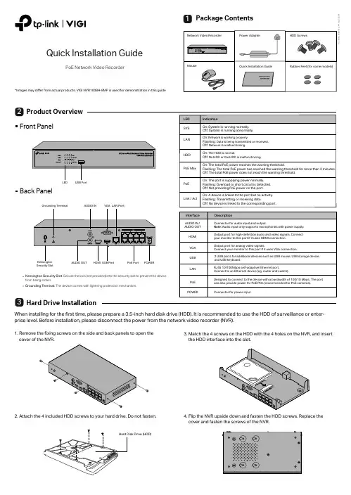
Product OverviewHard Drive InstallationQuick Installation GuidePoE Network Video RecorderPackage Contents1322. Attach the 4 included HDD screws to your hard drive. Do not fasten.1. Remove the fixing screws on the side and back panels to open the Front PanelBack PanelWhen installing for the first time, please prepare a 3.5-inch hard disk drive (HDD). It is recommended to use the HDD of surveillance or enter-prise level. Before installation, please disconnect the power from the network video recorder (NVR).3. Match the 4 screws on the HDD with the 4 holes on the NVR, and insert the HDD interface into the slot.4. Flip the NVR upside down and fasten the HDD screws. Replace the cover and fasten the screws of the NVR.*Images may differ from actual products. VIGI NVR1008H-8MP is used for demonstration in this guideSecurity SlotKensington Security Slot : Secure the lock (not provided) into the security slot to prevent the device from being stolen.Grounding T erminal: The device comes with lightning protection mechanism.Step 1. Connect your cameras to the PoE ports of the NVR or the same network as your NVR.Step 2. Follow the instructions to finish Quick Setup.1. Create a login password for the NVR and a preset password for your unset cameras.Note: Enter an email address for resetting the password of NVR or cameras.2. Click Auto Initialize and the NVR will automatically find and add the cameras inyour network.Note: If you don’t want to use Auto Initialize , click Manually Initialize and follow the Setup Wizard to add cameras in your network and complete the setup.Step 3. Right click on the Live View screen to open the Main Menu for management.(Optional) Step 4. Bind your NVR to a TP-Link ID for remote access and management.1. Right click on the Live View screen and click Settings .2. Click Cloud Services on the top, enter your TP-Link ID and password, and click Bind .Hardware ConnectionFollow the steps below to complete the hardware connection.1. Connect your monitor to the HDMI or VGA port according to the connection port it supports.2. Connect your monitor to a power source and turn it on.3. Connect the LAN port of the NVR to a network device with an Ethernet cable.4. Connect the provided USB Mouse to the USB Interface of the NVR.5. Connect the power adapter to the NVR.NVR can add and manage cameras in batches.* Here we use TP-Link cameras as an example. For other camera brands, please refer to their User Manuals to add the cameras.Configuration54(e.g. Router, Switch)More Management Methods1. Download the VIGI Security Manager on your computer at https:///support/download/vigi-security-manager/.2. Install the VIGI Security Manager and open it.3. NVR on the same network as your computer can be automatically discovered. Go to Settings > Discovered Devices , click Add , and follow the instructions to add your NVR.Method 1: Via the VIGI Se curity Manager (Windows only)You can add and manage your devices via any of the methods below.View live video and modify NVR settings on your computer.Method 3: Via a Web Brow serView live video and modify NVR settings via a web browser.Method 2: Via the TP-Lin k VIGI AppRemotely view live video, manage NVR, and get instant alerts.1. Download and install the2. Open the app and log in with your TP-Link ID. If you don’t have an account, sign up first.3. Tap the + button on the top right and follow the app instructions to add your NVR.orCautionsIf you want to turn off the NVR after installing the hard drive, right click on the Live View screen and click the Power button on Main Menu of your monitor. Do not unplug it directly.The input voltage should match the power requirements of the NVR.The buzzer on the NVR may be triggered when no hard drive is installed or the hard drive in the NVR hasn’t been initialized. Y ou can turn it off in Event-Exception Detection-Disk Exception .Note:Make sure your NVR can get access to the internet before binding.If you don’t have a TP-Link ID, sign up first.If your NVR fails to connect to the Internet, please refer to FAQ-Q3.For more instructions, please refer to the NVR’s User Guide.or Keyboard1. Find the NVR's IP address on your router’s client page.2. On your local computer, open a web browser and enter https://NVR’s IP address (https://192.168.0.240 by default).3. Select your Country/Region and Time Zone .4. Set a password to activate the NVR.Done. You can manage and change NVR settings, and add cameras on the web management page.。

网络摄像机快速指南前言本节内容的目的是确保用户通过本手册能够正确使用产品,以避免操作中的危险或财产损失。
在使用此产品之前,请认真阅读产品手册并妥善保存以备日后参考。
使用前说明●访问本公司官网()获取说明书、应用工具和开发资料。
●使用前请先对设备进行校时,校时的具体配置方法请参见《网络摄像机操作手册》。
符号约定对于文档中出现的符号,说明如下所示。
说明类文字,表示对正文的补充和解释。
注意类文字,表示提醒用户一些重要的操作或者防范潜在的伤害和财产损失危险。
警告类文字,表示有潜在风险,如果不加避免,有可能造成伤害事故、设备损坏或业务中断。
危险类文字,表示有高度潜在风险,如果不加避免,有可能造成人员伤亡的重大危险。
安全使用注意事项●产品安装使用过程中,必须严格遵守国家和使用地区的各项电气安全规定。
●请使用正规厂家提供的电源适配器,电源适配器具体要求参见产品参数表,建议为每台设备配备独立的适配器。
●根据国家相关标准,对弱电设备供电时,要求供电电流不超过8A并且功率不超过100W,防止发生安全事故。
●为减少火灾或电击危险,请勿让产品受到雨淋或受潮。
●应该在建筑物安装配线中组入易于使用的断电设备。
●在墙壁或天花板安装时,请确保产品固定牢固。
●如果产品工作不正常,请联系购买产品的商店或最近的服务中心,不要以任何方式拆卸或修改产品。
(对未经认可的修改或维修导致的问题,本公司不承担任何责任)。
●避免将产品安装到振动或冲击环境,并使产品远离电磁干扰的地点。
(忽视此项可能会损坏产品)。
●请勿直接触碰产品散热部件,以免烫伤。
●室内产品请勿安装在可能淋到水或其他液体的环境。
●请勿在极热、极冷、多尘或者高湿度的环境下使用产品,具体温、湿度要求参见产品的参数表。
●设备需存放于干燥无腐蚀性气体环境,避免阳光直射。
●避免将镜头对准强光(如灯光照明、太阳光或激光束等),否则会损坏图像传感器。
●避免热量积蓄,保持产品周边通风流畅。
●请勿直接触碰到图像传感器,若有必要清洁,请将柔软的干净布用酒精稍微湿润,轻轻拭去尘污;当产品不使用时,请将防尘盖加上,以保护图像传感器。

DS-K1T804B指纹门禁一体机快速入门指南UD22706B为了提高产品网络使用的安全性,设置的密码长度需达到8-16海康云眸Lite小程序码海康云眸客户服务公众号PA SS产品质量合格证Qualification Card扫描下方二维码获取设备用户手册《电器电子产品有害物质限制使用管理办法》限制物质或元素标识表本产品超过使用期限或者经过维修无法正常工作后,不应随意丢弃,请交由有废电器电子产品处理资格的企业处理,正确的方法请查阅国家或当地有关废弃电器电子产品处理的规定。
版权所有©杭州海康威视数字技术股份有限公司2021。
保留一切权利。
本手册的任何部分,包括文字、图片、图形等均归属于杭州海康威视数字技术股份有限公司或其子公司(以下简称“本公司”或“海康威视”)。
未经书面许可,任何单位和个人不得以任何方式摘录、复制、翻译、修改本手册的全部或部分。
除非另有约定,本公司不对本手册提供任何明示或默示的声明或保证。
关于本产品本手册描述的产品仅供中国大陆地区销售和使用。
本产品只能在购买地所在国家或地区享受售后服务及维保方案。
关于本手册本手册仅作为相关产品的指导说明,可能与实际产品存在差异,请以实物为准。
因产品版本升级或其他需要,海康威视可能对本手册进行更新,如您需要最新版手册,请您登录海康威视官网查阅()。
海康威视建议您在专业人员的指导下使用本手册。
• 为海康威视的注册商标。
• 本手册涉及的其他商标由其所有人各自拥有。
责任声明• 在法律允许的最大范围内,本手册以及所描述的产品(包含其硬件、软件、固件等)均“按照现状”提供,可能存在瑕疵或错误。
海康威视不提供任何形式的明示或默示保证,包括但不限于适销性、质量满意度、适合特定目的等保证;亦不对使用本手册或使用海康威视产品导致的任何特殊、附带、偶然或间接的损害进行赔偿,包括但不限于商业利润损失、系统故障、数据或文档丢失产生的损失。
• 您知悉互联网的开放性特点,您将产品接入互联网可能存在网络攻击、黑客攻击、病毒感染等风险,海康威视不对因此造成的产品工作异常、信息泄露等问题承担责任,但海康威视将及时为您提供产品相关技术支持。

NVMS 管理一体机用户手册1 简介1.1 前面接口及指示灯说明以下图标仅供参考,具体接口及指示灯请参照实物。
电源开关硬盘指示灯;绿灯闪烁表示硬盘有读写//复位按键电源指示灯USB 接口网络连接指示灯,绿色灯亮表示网络连接正常;绿灯闪烁表示有数据传输1.2 后背板接口说明序号 说明序号 说明1 鼠标或键盘接口 9 音频输入(橙色)2 VGA 接口 10 后置扬声器(黑色)3 DVI 接口 11 光纤数字音频输出4 HDMI 接口12 音频输入(浅蓝色) 5 RJ-45 网络接口(LAN1) 13 前置扬声器(绿黄色) 6 USB3.0 接口(1~2) 14 耳机孔(粉色)7 RJ-45 网络接口(LAN2) 15 RJ-45 网络接口(LAN3) 8USB3.0 接口(3~4)16RJ-45 网络接口(LAN4)2 登录及网络配置启动服务器,启动前请确保电源,网线,显示器等均连接无误。
系统启动完毕后,屏幕上会显示如下登录框。
默认用户名:admin; 默认密码:123456勾选“记住密码”,下次登录可以不用输入密码直接登录。
勾选“自动登录”,下次启动服务器时可自动登录进入。
若忘记登录密码,可点击【重置密码】,确认服务器IP和配置服务器端口是正确的情况下,通过回答密保问题重置密码。
首次登录后,用户可对超级管理员进行密保设置以方便找回密码,具体设置请参见说明书用户管理章节。
●网络配置登录设备后,进入本地配置→网络配置界面,根据实际网络,配置设备网络参数。
在此界面用户可自行配置网络参数。
我们推荐设置勾选组IP(设置后4网口以自适应负载均衡模式自动绑定使用),同时出厂也是默认勾选。
主界面介绍客户端主界面主要分五个部分,各部分说明如下表:区域说明区域说明1 菜单栏 4 状态栏2 标签栏(显示已启动的功能页面) 5 报警信息栏3 功能区;点击显示更多菜单3 设备管理3.1添加编码设备在主界面,点击“设备管理”菜单,进入设备管理界面,如下图所示:点击【添加】按钮,如下图所示:用户可通过快速添加、手动添加以及主动上报等方式添加监控设备(例如:普通IPC/NVR/DVR,人脸IPC/人脸NVR,人脸平板,警戒IPC,车牌识别IPC等)。
TM Quick Start Guide of Hikvision IP Camera & Synology NASConnectionIndex1. Adding DS112j to DS-2CD2112-I5 via NFS Mount Type (4)2. Notes of using NFS mount type on DS112j (7)3. Adding DS112j to DS-2CD2112-I5 via CIFS Mount Type (9)4. Notes of using CIFS mount type on DS112j: (13)About this DocumentThis manual applies to the following devices and Hikvision IP camera DS-2CD2211-I5 and Synology NAS DS112j are used as examples in it.[1]DS-2CD63xx series IP cameras do not support Synology NAS connection via CIFS mount type.1.Adding DS112j to DS-2CD2112-I5 via NFS Mount TypeMain Steps:1.Log in the web page of the DS112j. The IP address of DS112j in US office is http://10.102.103.206:5000 anduser name/password is admin/12345.2.Click Control Panel, and in the pop-up message box, click File Services. Under Win/Mac/NFS tab, enable theNFS by tick the box in front of Enable NFS and click Apply to save the settings.3.Create a Shared Folder:Then click Shared Folder and create a shared folder. In this case, we named it“TestNas” and click OK.4.Then go to NFS Permissions tab and click Create button. In pop-up message box, enter the IP address. In thiscase, my IP address is 10.102.103.x, so I entered 10.102.103.0/24 (Note:/24 means that the subnet mask is 255.255.255.0). And then all the IP cameras in this segment can be mounted on this directory. Please also select No mapping for Squash option. Click OK to save the settings.5.And under NFS permission tab, you will see the mount path (file path) is /volume1/TestNas6.Add NAS to an IP camera: Go to web client of DS-2CD2112-I5 and select NFS as the mounting type andinput the server address and file path, then click save.Note: NFS mounting type does not require user name and password.7.Go back to Storage Management, tick the checkbox of the HDD No. and click Format. After it is formatted,the NAS can be used for recording.2.Notes of using NFS mount type on DS112j1.DS112j only supports adding one HDD so it does not support disk group management as shown in the figurebelow.2.DS112j only supports creating one volume (as shown in the figure below) and a volume can only be attachedto one IP camera when using NFS mount type. There might be confliction that causes HDD error and video loss if a volume is attached to more than one IP camera.3. A shared folder can be only attached to one IP camera. There might be confliction that causes HDD error andvideo loss if a shared folder is attached to more than one IP camera.4.When using NFS mount type, a shared folder will use up all the space in a volume, so it is suggested thatcreating only one shared folder in a volume for only one IP camera to use.5.NFS mount type does not require user name/password when it is attached to an IP camera, so there is noneed to create user on the Synology NAS as well.6.When assign the NFS permission for NFS mount type, please select No mapping for Squash option as shownin the figure below.7.When using NFS mount type, the file path format filled in an IP camera is /volume id/name of shared folder.For example, if the volume id is 1 and the name of shared folder is TestNas, the file path is /volume3/TestNas.3.Adding DS112j to DS-2CD2112-I5 via CIFS Mount TypeMain Steps:1.Log in the web page of the DS112j. The IP address of DS112j in US office is http://10.102.103.206:5000 anduser name/password is admin/12345.2.Create a Shared Folder: Click Control Panel, and in the pop-up message box, click Shared Folder. Input thename of the new folder and click OK. In this case, we named it “TestCIFS” under General tab and click OK.The file path is /TestCIFS in this case then.3.Create a User: Click Control Panel, and in the pop-up message box, click User and click Add button. Then youwill see the message box below, input the user name and password under Info tab. In this case, ipc_test is the user name and 12345 is the password for the newly added user. Click OK to save the settings.4.Then go to User groups tab and select users by ticking the box on the right side. Click OK to go to next step.5.Go to Permissions and assign the Read/Write permission of TestCIFS folder to the newly added user –ipc_test and click OK.6.In the following interface, you can configure the upper limit of the storage space. Quota control is only validwhen using CIFS protocol and quota size cannot be zero or empty (For NFS protocol, it is invalid). In this case, we tick the checkbox of Enable Quota, and enter the number 200, then the user ipc_test is able to use 200G space on the volume 1. If you want the ipc_test to use all the storage space of the volume 1, you can leave the Enable Quota unchecked which is as known as No Quota Mode. After configuration, click OK to finish.7.Add NAS to an IP camera: In the web client of DS-2CD2212-I5, select SMB/CIFS as the mounting type andinput the file path, user info and server address, and then click save.8.Go back to Storage Management, tick the checkbox of the HDD No. and click Format. After it is formatted,the HDD can be used for recording.4.Notes of using CIFS mount type on DS112j:1.DS112j only supports adding one HDD so it does not support disk group management as shown in the figurebelow.2.DS112j only supports creating one volume (as shown in the figure below). If you want to attach more thanone IP camera to a volume, please create multiple shared folders and users on DS112j. Note that quota mode must be enabled on every single user and the total quota size of all users must be smaller than the volume size. After that you should assign each shared folder to each user and then input each shared folder (file path) and user info in the web client of each IP camera.3. A shared folder can be only attached to one IP camera. There might be confliction that causes HDD error andvideo loss if a shared folder is attached to more than one IP camera.4.In quota mode, if the quota size of a user is changed, you have to format the HDD again on the web client ofthe IP camera before use it again.5.CIFS mount type requires user name/password when it is attached to an IP camera, so you need to create auser on the Synology NAS.6.When using CIFS mount type, the file path format filled in an IP camera is /name of shared folder. Forexample, if the name of shared folder is TestCIFS, the file path is /TestCIFS.。
Network Video RecorderQuick Start GuideTABLE OF CONTENTSChapter1 Panels Description (8)1.1 Front Panel (8)1.2 Rear Panel (9)NVR-100H-D and NVR-100MH-D Series (9)NVR-100H-D/P and NVR-100MH-D/P Series (10)Chapter 2 Installation and Connections (11)2.1 NVR Installation (11)2.2 Hard Disk Installation (11)2.3 HDD Storage Calculation Chart (13)Chapter 3 Menu Operation (14)3.1 Startup and Shutdown (14)3.2 Activate Your Device (14)3.3 Set the Unlock Pattern for Login (15)3.4 User Login (16)3.5 Network Settings (16)3.6 Add IP Cameras (17)3.7 Live View (18)3.8 Recording Settings (18)3.9 Playback (19)Chapter 4 Accessing by Web Browser (21)Quick Start GuideCOPYRIGHT ©2019 Hangzhou Hikvision Digital Technology Co., Ltd.ALL RIGHTS RESERVED.Any and all information, including, among others, wordings, pictures, graphs are the properties of Hangzhou Hikvision Digital Technology Co., Ltd. or its subsidiaries (hereinafter referred to be “Hikvision”). This user manual (hereinafter referred to be “the Manual”) cannot be reproduced, changed, translated, or distributed, partially or wholly, by any means, without the prior written permission of Hikvision. Unless otherwise stipulated, Hikvision does not make any warranties, guarantees or representations, express or implied, regarding to the Manual.About this ManualThis Manual is applicable to Network Video Recorder (NVR).The Manual includes instructions for using and managing the product. Pictures, charts, images and all other information hereinafter are for description and explanation only. The information contained in the Manual is subject to change, without notice, due to firmware updates or other reasons. Please find the latest version in the company website (/en/).Please use this user manual under the guidance of professionals.Trademarks Acknowledgementand other Hikvision’s trademarks and logos are the properties of Hikvision in various jurisdictions. Other trademarks and logos mentioned below are the properties of their respective owners.The terms HDMI and HDMI High-Definition Multimedia Interface, and the HDMI Logoare trademarks or registered trademarks of HDMI Licensing Administrator, Inc. in the United States and other countries.Legal DisclaimerTO THE MAXIMUM EXTENT PERMITTED BY APPLICABLE LAW, THE PRODUCT DESCRIBED, WITH ITS HARDWARE, SOFTWARE AND FIRMWARE, IS PROVIDED “AS IS”, WITH ALL FAULTS AND ERRORS, AND HIKVISION MAKES NO WARRANTIES, EXPRESS OR IMPLIED, INCLUDING WITHOUT LIMITATION, MERCHANTABILITY, SATISFACTORY QUALITY, FITNESS FOR A PARTICULAR PURPOSE, AND NON-INFRINGEMENT OF THIRD PARTY. IN NO EVENT WILL HIKVISION, ITS DIRECTORS, OFFICERS, EMPLOYEES, OR AGENTS BE LIABLE TO YOU FOR ANY SPECIAL, CONSEQUENTIAL, INCIDENTAL, OR INDIRECT DAMAGES, INCLUDING, AMONG OTHERS, DAMAGES FOR LOSS OF BUSINESS PROFITS, BUSINESS INTERRUPTION, OR LOSS OF DATA OR DOCUMENTATION, IN CONNECTION WITH THE USE OF THIS PRODUCT, EVEN IF HIKVISION HAS BEEN ADVISED OF THE POSSIBILITY OF SUCH DAMAGES.REGARDING TO THE PRODUCT WITH INTERNET ACCESS, THE USE OF PRODUCT SHALL BE WHOLLY AT YOUR OWN RISKS. HIKVISION SHALL NOT TAKE ANY RESPONSIBILITES FOR ABNORMAL OPERATION, PRIVACY LEAKAGE OR OTHER DAMAGES RESULTING FROM CYBER ATTACK, HACKER ATTACK, VIRUS INSPECTION, OR OTHER INTERNET SECURITY RISKS; HOWEVER, HIKVISION WILL PROVIDE TIMELY TECHNICAL SUPPORT IF REQUIRED.SURVEILLANCE LAWS VARY BY JURISDICTION. PLEASE CHECK ALL RELEVANT LAWS IN YOUR JURISDICTION BEFORE USING THIS PRODUCT IN ORDER TO ENSURE THAT YOUR USE CONFORMSTHE APPLICABLE LAW. HIKVISION SHALL NOT BE LIABLE IN THE EVENT THAT THIS PRODUCT IS USED WITH ILLEGITIMATE PURPOSES.IN THE EVENT OF ANY CONFLICTS BETWEEN THIS MANUAL AND THE APPLICABLE LAW, THE LATER PREVAILS.Regulatory InformationFCC InformationPlease take attention that changes or modification not expressly approved by the party responsible for compliance could void the user’s authority to operate the equipment.FCC compliance: This equipment has been tested and found to comply with the limits for a Class A digital device, pursuant to part 15 of the FCC Rules. These limits are designed to provide reasonable protection against harmful interference when the equipment is operated in a commercial environment. This equipment generates, uses, and can radiate radio frequency energy and, if not installed and used in accordance with the instruction manual, may cause harmful interference to radio communications. Operation of this equipment in a residential area is likely to cause harmful interference in which case the user will be required to correct the interference at his own expense.FCC ConditionsThis device complies with part 15 of the FCC Rules. Operation is subject to the following two conditions:1. This device may not cause harmful interference.2. This device must accept any interference received, including interference that may cause undesired operation.EU Conformity StatementThis product and - if applicable - the supplied accessories too are marked with "CE" and comply therefore with the applicable harmonized European standards listed under the EMC Directive 2014/30/EU, the LVD Directive 2014/35/EU, the RoHS Directive 2011/65/EU.2012/19/EU (WEEE directive): Products marked with this symbol cannot be disposed of as unsorted municipal waste in the European Union. For proper recycling, return this product to your local supplier upon the purchase of equivalent new equipment, or dispose of it at designated collection points. For more information see: 2006/66/EC (battery directive): This product contains a battery that cannot be disposed of as unsorted municipal waste in the European Union. See the product documentation for specific battery information. The battery is marked with this symbol, which may include lettering to indicate cadmium (Cd), lead (Pb), or mercury (Hg). For proper recycling, return the battery to your supplier or to a designated collection point. For more information see: Industry Canada ICES-003 ComplianceThis device meets the CAN ICES-3 (A)/NMB-3(A) standards requirements.Applicable ModelsThis manual is applicable to the models listed in the following table.Series ModelNVR-100H-D NVR-104H-D NVR-108H-DNVR-100H-D/P NVR-104H-D/4P NVR-108H-D/8PNVR-100MH-D NVR-104MH-D NVR-108MH-DNVR-100MH-D/P NVR-104MH-D/4P NVR-108MH-D/8PSymbol ConventionsThe symbols that may be found in this document are defined as follows.Symbol DescriptionProvides additional information to emphasize or supplementimportant points of the main text.Indicates a potentially hazardous situation, which if not avoided,could result in equipment damage, data loss, performancedegradation, or unexpected results.Indicates a hazard with a high level of risk, which if not avoided, willresult in death or serious injury.Safety Instructions●Proper configuration of all passwords and other security settings is the responsibility of theinstaller and/or end-user.●In the use of the product, you must be in strict compliance with the electrical safetyregulations of the nation and region. Please refer to technical specifications for detailedinformation.●Input voltage should meet both the SELV (Safety Extra Low Voltage) and the Limited PowerSource with 100~240 VAC, 48 VDC or 12 VDC according to the IEC60950-1 standard. Please refer to technical specifications for detailed information.●Do not connect several devices to one power adapter as adapter overload may causeover-heating or a fire hazard.●Please make sure that the plug is firmly connected to the power socket.●If smoke, odor or noise rise from the device, turn off the power at once and unplug the powercable, and then please contact the service center.●If the POE ports of device do not comply with Limited Power Source, the additional equipmentconnected to POE ports shall have fire enclosure.●The USB interface of the /P devices can be connected with the mouse and U-flash disk storagedevice only.Preventive and Cautionary TipsBefore connecting and operating your device, please be advised of the following tips:●Ensure unit is installed in a well-ventilated, dust-free environment.●Unit is designed for indoor use only.●Keep all liquids away from the device.●Ensure environmental conditions meet factory specifications.●Ensure unit is properly secured to a rack or shelf. Major shocks or jolts to the unit as a result ofdropping it may cause damage to the sensitive electronics within the unit.●Use the device in conjunction with an UPS if possible.●Power down the unit before connecting and disconnecting accessories and peripherals.● A factory recommended HDD should be used for this device.●Improper use or replacement of the battery may result in hazard of explosion. Replace withthe same or equivalent type only. Dispose of used batteries according to the instructionsprovided by the battery manufacturer.Power Supply InstructionsUse only power supplies listed in the user instructions.NVR Models Standard Power Supply Models ManufacturerNVR-104H-D NVR-108H-D NVR-104MH-D NVR-108MH-D EuropeanMSA-C1500IC12.0-18P-DE MOSO Power Supply Technology Co., LtdADS-26FSG-12 12018EPG Shenzhen HONOR Electronic Co., LtdKL-AD3060VA Xiamen Keli Electronics Co., LtdKPD-018-VI Channel Well Technology Co., Ltd BritishADS-25FSG-12 12018GPB Shenzhen HONOR Electronic Co., LtdMSA-C1500IC12.0-18P-GB MOSO Power Supply Technology Co., LtdADS-26FSG-12 12018EPB Shenzhen HONOR Electronic Co., LtdNVR-104H-D/4PNVR-108H-D/8P NVR-104MH-D/4P NVR-108MH-D/8P UniversalMSP-Z1360IC48.0-65W MOSO Power Supply Technology Co., LtdMSA-Z1040IS48.0-65W-Q MOSO Power Supply Technology Co., LtdMSA-Z1360IS48.0-65W-QMOSO Power Supply Technology Co., Ltd●The power supplies list above is for EU countries only.●The power supplies list is subject to change without prior notice.Chapter1 Panels Description 1.1 Front PanelFigure 1-1NVR-100H-D (/P) SeriesFigure 1-2NVR-100MH-D (/P) SeriesTable 1-1Description of Front Panel No. Icon Description1 Indicator turns red when NVR is powered up.2 Indicator lights in red when data is being read from or written to HDD.3 Indicator blinks blue when network connection is functioning properly.1.2 Rear PanelNVR-100H-D and NVR-100MH-D SeriesFigure 1-3NVR-100H-D Rear PanelFigure 1-4NVR-100MH-D Rear PanelNo. Item Description1 Power Supply 12 VDC power supply.2 VGA Interface DB9 connector for VGA output. Display local videooutput and menu.3 HDMI Interface HDMI video output connector.4 USB Interface Universal Serial Bus (USB) ports for additional devicessuch as USB mouse and USB Hard Disk Drive (HDD).5 LAN Network Interface 10/100 Mbps self-adaptive Ethernet interface.6 Ground Ground (needs to be connected when NVR starts up).NVR-100H-D/P and NVR-100MH-D/P SeriesFigure 1-5NVR-100H-D/P Rear PanelFigure 1-6NVR-100MH-D/P Rear PanelTable 1-3Description of Rear Panel No. Item Description1 Power Supply 12 VDC power supply.2 VGA Interface DB9 connector for VGA output. Display local videooutput and menu.3 HDMI Interface HDMI video output connector.4 USB Interface Universal Serial Bus (USB) ports for additional devicessuch as USB mouse and USB Hard Disk Drive (HDD).5 LAN Network Interface 10/100 Mbps self-adaptive Ethernet interface.6 Ground Ground (needs to be connected when NVR starts up).7 Network Interfaces withPoE functionNetwork interfaces for the cameras and to providepower over Ethernet.4 interfaces for /4P models and 8 interfaces for /8Pmodels.Chapter 2 Installation and Connections2.1 NVR InstallationDuring installation of the NVR:●Use brackets for rack mounting.●Ensure ample room for audio and video cables.●When routing cables, ensure that the bend radius of the cables are no less than five times thanits diameter.●Connect the alarm cable.●Allow at least 2cm (≈0.75-inch) of space between racks mounted devices.●Ensure the NVR is grounded.●Environmental temperature should be within the range of -10 to +55º C, +14 to +131º F.●Environmental humidity should be within the range of 10% to 90%.2.2 Hard Disk InstallationBefore you start:Disconnect the power from the NVR before installing a hard disk drive (HDD). A factory recommended HDD should be used for this installation.Tools Required: Screwdriver.Step 1Remove the cover from the device by unfastening the screws on the bottom.Figure 2-1Remove the CoverStep 2Place the HDD on the bottom of the device and then fasten the screws on the bottom to fix the HDD.Figure 2-2Fix the HDDStep 3Connect one end of the data cable to the motherboard of NVR and the other end to the HDD.Step 4Connect the power cable to the HDD.Figure 2-3Connect CablesStep 5Re-install the cover of the NVR and fasten screws.2.3 HDD Storage Calculation ChartThe following chart shows an estimation of storage space used based on recording at one channel for an hour at a fixed bit rate.Bit Rate Storage Used96K42M128K56M160K70M192K84M224K98M256K112M320K140M384K168M448K196M512K225M640K281M768K337M896K393M1024K450M1280K562M1536K675M1792K787M2048K900M4096K 1.8G8192K 3.6G16384K 7.2GPlease note that supplied values for storage space used is just for reference. The storage values in the chart are estimated by formulas and may have some deviation from actual value.Chapter 3 Menu Operation3.1 Startup and ShutdownProper startup and shutdown procedures are crucial to expanding the life of the NVR.To start your NVR:Step 1Check the power supply is plugged into an electrical outlet. It is HIGHLY recommended that an Uninterruptible Power Supply (UPS) be used in conjunction with the device. The Powerbutton) on the front panel should be red, indicating the device is receiving the power.Step 2Press the power switch on the panel. The Power LED should turn blue. The unit will begin to start.After the device starts up, the wizard will guide you through the initial settings, including modifying password, date and time settings, network settings, HDD initializing, and recording.To shut down the NVR:Step 1Go to Menu > Shutdown.Figure 3-1ShutdownStep 2Select Shutdown.Step 3Click Yes.3.2 Activate Your DevicePurpose:For the first-time access, you need to activate the device by setting an admin password. No operation is allowed before activation. You can also activate the device via Web Browser, SADP or client software.Step 1Input the same password in Create New Password and Confirm New Password.Step 2(Optional) Use customized password to activate and add network camera(s) connected to the device.1)Uncheck Use Channel Default Password.2)Enter a password in IP Camera Activation.Figure 3-2Set Admin PasswordSTRONG PASSWORD RECOMMENDED–We highly recommend you create a strong password of your own choosing (Using a minimum of 8 characters, including at least three of the following categories: upper case letters, lower case letters, numbers, and special characters.) in order to increase the security of your product. And we recommend you reset your password regularly, especially in the high security system, resetting the password monthly or weekly can better protect your product.Step 3Click OK.3.3 Set the Unlock Pattern for LoginAdmin can use the unlock pattern for device login.For devices with PoE function, you can draw the device unlock pattern after activation. For other devices, the unlock pattern interface will show after the first-time login.Step 1Use the mouse to draw a pattern among the 9 dots on the screen. Release the mouse when the pattern is done.Figure 3-3Draw the Pattern●Connect at least 4 dots to draw the pattern.●Each dot can be connected for once only.Step 2Draw the same pattern again to confirm it. When the two patterns match, the pattern is configured successfully.3.4 User LoginPurpose:If NVR has logged out, you must login the device before operating the menu and other functions. Step 1Select the User Name in the dropdown list.Figure 3-4LoginStep 2Input Password.Step 3Click OK.In the Login dialog box, if you enter the wrong password 7 times, the current user account will be locked for 60 seconds.3.5 Network SettingsPurpose:Network settings must be properly configured before you operate NVR over network.Step 1Enter the general network settings interface.Menu > Configuration > Network > GeneralFigure 3-5Network SettingsStep 2Configure the following settings: NIC Type, IPv4 Address, IPv4 Gateway, MTU and DNS Server.Step 3If the DHCP server is available, you can check the checkbox of DHCP to automatically obtain an IP address and other network settings from that server.Step 4Click Apply.3.6 Add IP CamerasPurpose:Before you can get live video or record the video files, you should add the network cameras to the connection list of the device.Before you start:Ensure the network connection is valid and correct, and the IP camera to add has already been activated. Please refer to the User Manual for activating the inactive IP camera.You can select one of the following three options to add the IP camera.OPTION 1:Step 1Click to select an idle window in the live view mode.Step 2Click in the center of the window to pop up the Add IP Camera interface.Figure 3-6Add IP CameraStep 3Select the detected IP camera and click Add to add it directly, and you can click Search to refresh the online IP camera manually.Or you can choose to custom add the IP camera by editing the parameters in thecorresponding text field and then click Add to add it.3.7 Live ViewIcons are provided on screen in Live View mode to indicate camera status. These icons include: Live View IconsIn the live view mode, there are icons at the upper-right corner of the screen for each channel, showing the status of the record and alarm in the channel for quick reference.Alarm (video loss, tampering, motion detection, VCA or sensor alarm)Record (manual record, continuous record, motion detection, VCA or alarm triggered record)Alarm and RecordEvent/Exception (event and exception information, appears at the lower-left corner of the screen.)3.8 Recording SettingsBefore you start:Make sure that the disk has already been installed. If not, please install a disk and initialize it. You may refer to the user manual for detailed information.Purpose:Two kinds of record types are introduced in the following section, including Instant Record andAll-day Record. And for other record types, you may refer to the user manual for detailed information.After rebooting all the manual records enabled are canceled.Step 1On the live view window, right lick the window and move the cursor to the Start Recording option, and select Continuous Record or Motion Detection Record on your demand.Figure 3-7Start Recording from Right-click MenuStep 2Click Yes in the pop-up Attention message box to confirm the settings. All the channels will start to record in the selected mode.3.9 PlaybackThe recorded video files on the hard disk can be played back in the following modes: instant playback, all-day playback for the specified channel, and playback bynormal/event/smart/tag/sub-periods/external file search.Step 1Enter playback interface.Click Menu > Playback or from the right-click menuStep 2Check the checkbox of channel(s) in the channel list and then double-click to select a date on the calendar.Step 3You can use the toolbar in the bottom part of Playback interface to control playing progress.Figure 3-8 Playback InterfaceStep 4 Select the channel(s) to or execute simultaneous playback of multiple channels.Chapter 4 Accessing by Web BrowserYou shall acknowledge that the use of the product with Internet access might be under network security risks. For avoidance of any network attacks and information leakage, please strengthen your own protection. If the product does not work properly, please contact with your dealer or the nearest service center.Purpose:You can get access to the device via web browser. You may use one of the following listed web browsers: Internet Explorer 6.0, Internet Explorer 7.0, Internet Explorer 8.0, Internet Explorer 9.0, Internet Explorer 10.0, Internet Explorer 11.0, Apple Safari, Mozilla Firefox, and Google Chrome. The supported resolutions include 1024*768 and above.Step 1Open web browser, input the IP address of the device and then press Enter.Step 2Login to the device.If the device has not been activated, you need to activate the device first before login.Figure 4-1Set Admin Password1)Set the password for the admin user account.2)Click OK.STRONG PASSWORD RECOMMENDED–We highly recommend you create a strong password of your own choosing (using a minimum of 8 characters, including upper case letters, lower case letters, numbers, and special characters) in order to increase the security of your product. And we recommend you reset your password regularly, especially in the high security system, resetting the password monthly or weekly can better protect your product.If the device is already activated, enter the user name and password in the login interface, and click Login.Figure 4-2LoginStep 3Install the plug-in before viewing the live video and managing the camera. Please follow the installation prompts to install the plug-in.You may have to close the web browser to finish the installation of the plug-in.After login, you can perform the operation and configuration of the device, including the live view, playback, log search, configuration, etc.03041041090702。
HIKVISION.CAVIDEO SECURITY SOLUTIONLooking for High Performance? Looking for affordable? Lookat HiLook. HiLook, Hikvision’s offshoot brand, hits the bullseyefor the entry-level video security market, providing very cost-effective, easy-to-use and reliable products and services.Reliable Quality Ease of UseHILOOK QUICK GUIDE 20223Safe and SoundEver So ClearCameras with resolutions up to 8 MP capture rich details with widercoverage, providing strong evidence for post-event search.HILOOK QUICK GUIDE 20224Ever So Evident Integrating audio into CCTV security system is a groundbreaking advancement, providing users with more situational awareness andmore evidence after an event. Combining audio and video enhances security and will be universal for the video security industry in the future.light works to guarantee colorful images when in zero light environments.produce brighter images.utilization of available light.light works to guarantee colorful images when in zero-light environments.produce brighter images.utilization of available light.light works to guarantee colorful images when in zero-light environments.produce brighter images.utilization of available light.HILOOK QUICK GUIDE 20225HIGH-EFFICIENCY CODECWIDE DYNAMIC RANGE FOREXCELLENT IMAGINGWide Dynamic Range (WDR) technology enables cameras tomaintain image fidelity without detail loss when there is harsh backlighting. The 120 dB WDR integrated into HiLook series’ cameras ensures accurate onscreen colour and detail even with backlitenvironments, where conventional cameras would capture onlyobscured silhouettes.NGE FOR NGWDR WIDE DYNAMIC RANGE FOR EXCELLENT IMAGING WDaytime Night 24-Hour recording file size (GB) comparing H.264, H.265, and H.265+*Data was tested in a common scene; for reference only.24-H o u r F i l e S i z e (G B )25H.264H.265H.265+5cameras 10cameras 20+cameras 20 MB Broadband NetworkH.264H.265H.265+0.5month 1month 2month Eight 2-MP camerasFive 1-TB HDDs HILOOK QUICK GUIDE 20226SEE WHO'S THERE, WHEREVER AND WHENEVERThe HiLookVision or Hik-Connect app allows live viewing from anywhere and at any time via smart phones, and sends timely notifications and alarms to end-users when events occur.Users can also stream the live feed using the HiLookVision PC Client or monitors connected to a DVR or NVR for more details and better viewing experience.KEEPING AN EYE ON THINGSSelect NVR models allow separate video channel output to more than one monitors, you can monitor multiple channels simultaneously andmore conveniently.HiLook productsHiLookVision PC ClientVGAHILOOK QUICK GUIDE 20227SMALL BUSINESS SOLUTIONLAN For small business applicationssuch as shops, retail stores,pharmacies, coffee shopsand restaurants, owners geta standard security systemin a cost-effective way. Thestandard solution is simpleand reliable, requires a modestoutlay and guarantees excellentperformance. It comprises out-of-the-box recording equipmentand HD megapixel cameras withthe option of local or remoterealtime viewing.HILOOK QUICK GUIDE 20228PLUG AND PLAYPlug-and-play systems are available either with PoE models oranalog products. Automatic connection is supported by all HiLookproducts, non-PoE models included.As a compact solution for the SSMB market, HiLook offers thesimplest solutions for security management.Simple and concise designwith only four necessarymodels on the dashboardheader, making it easierfor users to view live,search, and set alarmschedules when needed.E-UI: Efficient User Interface for HiLookNVRs and DVRsHILOOK QUICK GUIDE 20229Forgot a Password? Just Scan and Reset.Users can reset their NVR or DVR password using theHiLookVision app with a registered account that is boundwith their device account. Resetting a password via email is also supported. Both methods are simple and safe.Tips: The HiLookVision accout needs to be bound with devices in advance, so we highly recommend binding the device to your HiLookVision app account during activation.01Choose "Verify with HiLookVision"02Scan the QR code on the GUI and get a verification code 03Key in the verification code and resetpasswordHILOOK QUICK GUIDE 202210IP SOLUTIONWith an incredible cost-to-performance ratio, the HiLook Seriesboasts the most advanced features for the price: the H.265+high-efficiency codec for maximum bandwidth and data storageefficiency, up to 4K super-high-definition imaging, EXIR 2.0 for higherinfrared luminous efficiency, and wide dynamic range to balancecolour and brightness under harsh lighting conditions. HiLook seriesis a whole new look for high-performance, cost-effective videosurveillance for small-to-medium business applications.HILOOK QUICK GUIDE 202211IP HiLook Value L3 Series Fixed-lens domeIPC-T249H• 4 MP, 2.8/4 mm lens • H.265+• 24/7 colourful imaging • Metal • IP67IPC-T240H• 4 MP, 2.8/4 mm lens • 120 dB WDR • H.265+• 3D DNR • POE • Metal • IP67IPC-T280H• 8 MP, 3840×2160 resolution • 2.8/4 mm lens options • 120 dB WDR • H.265+• POE • Metal • IP67IP HiLook Value L3 Series Fixed-lens bulletIPC-B449H• 4 MP, 2560×1440 resolution • 4 mm lens • H.265+• 24/7 colourful imaging • IP67IPC-B440H• 4 MP, 2560×1440 resolution • 4 mm lens • 120 dB WDR • H.265+• 3D DNR • POE • IP67IPC-B480H• 8 MP, 3840×2160 resolution • 4 mm lens • 120 dB WDR • H.265+• POE • IP67IP HiLook Value L3 Series Vari-focal bulletIPC-B640H-Z• 4 MP, 2560×1440 resolution • 2.8 to 12 mm • 120 dB WDR • H.265+• Metal • IP67IP HiLook Value L3 Series Vari-focal domeIPC-T641H-Z• 4 MP, 2560×1440 resolution • 2.8 to 12 mm • 120 dB WDR • H.265+• Metal • IP67Lite LiteHILOOK QUICK GUIDE 202212HiLook Value NVRNVR-104MH-C/4P• Up to 4-ch IP camera inputs • H.265+/H.265/H.264+/H.264• Up to 1-ch @ 8 MP or 5-ch @ 1080P decoding capacity• Up to 40 Mbps incoming bandwidth NVR-208MH-C/8P• Up to 8-ch IP camera inputs • H.265+/H.265/H.264+/H.264• Up to 1-ch @ 8 MP or 5-ch @ 1080P decoding capacity• Up to 80 Mbps incoming bandwidth NVR-216MH-C/16P• Up to 16-ch IP camera inputs • H.265+/H.265/H.264+/H.264• Up to 1-ch @ 8 MP or 5-ch @ 1080P decoding capacity• Up to 160 Mbps incoming bandwidthPTZ Network Dome HiLook SeriesPTZ-N2404I-DE3• 4 MP, 2560×1440 resolution• Two-inch 4 MP camera with pan, tilt and zoom (4x) ability • H.265+• 120 dB true WDR• Up to 20 m enhanced IR • IP66, IK10IP POE KITIK-4248TH-MH/P • H.265• WDR • 3D DNR • POE • IP67• NVR-104MH-C/4P + IPC-T280H*4 + 2T 3.5 HDDIK-4284TH-MH/P • H.265• WDR • 3D DNR • POE • IP67• NVR-208MH-C/8P + IPC-T249H*4 + 2T 3.5 HDDIK-6288TH-MH/P • H.265• WDR • 3D DNR • POE• IP67• NVR-208MH-C/8P + IPC-T280H*6 + 2T 3.5 HDDLiteHILOOK QUICK GUIDE 202213TURBO HD SOLUTIONWith an incredible cost-to-performance ratio, the HiLook Seriesboasts the most advanced features for the price. It offers theH.265 Pro+ highefficiency codec for maximum bandwidth and datastorage efficiency, up to 5 MP super-high-definition imaging, EXIR forhigher infrared luminous efficiency, superior imaging performancein as little light as 0.005 lux, and PIR detection with strobe lightalarm. The HiLook Series is a whole new look for high-performance,cost-effective video surveillance for small-to-medium businessapplications.HILOOK QUICK GUIDE 202214TurboTHC HiLook 5MP SeriesTHC-B150-M· 5 MP, 2560×1944 resolution· 2.8/3.6 mm lens options· One port for four switchable signals(TVI/AHD/CVI/CVBS)· 20 m IR· IP66THC-T150-M· 5 MP, 2560×1944 resolution· 2.8/3.6 mm lens options· One port for four switchable signals(TVI/AHD/CVI/CVBS)· 20 m IR· IP66HiLook 4MP Series DVRDVR-204U-K1DVR-208U-M1DVR-216U-M2• HDTVI/AHD/CVI/CVBS/IP videoinput• Long distance transmission overUTP and coaxial cable• Encoding ability up to 8 MP @ 8 fps• Up to 10 TB capacity per HDD• Smart search for efficient playback• Deep learning powered humanand vehicle targets classification ofMotion Detection 2.0(M1 and M2 models only)THC HiLook 3K Series CameraTHC-B259-MS· 3K, 2960×1665 resolution· 2.8/3.6 mm lens options· 24/7 colour imagingTHC-T259-MS· 3K, 2960×1665 resolution· 2.8/3.6 mm lens options· 24/7 colour imaging· Audio with audio over coaxial cable· 40 m IR· IP66LiteHILOOK QUICK GUIDE 202215TechnicalSupport:**************************** www.hikvision.ca。
D861_QSG_FR_R1Série D8611/2Les panneaux arrière ci-dessous sont uniquement présentés à des fins d’illustration. Le panneau arrière de votre enregistreur peut paraître légèrement différent, avec tous lesmêmes ports à des endroits différents.Copyright © 2020 Lorex CorporationNos produits étant sans cesse améliorés, Lorex se réserve le droit de modifier la conception du produit, ses spécificationset son prix sans préavis et sans aucune obligation. E&OE. Tous droits réservés.Besoin d’aide?Rendez-vous sur notre site Web pour accéder aux mises à jour du logiciel etaux manuels d’instructions complets.Notez le mot de passe ci-dessous et gardez-le dans un endroit sûr :configuration initiale de l’enregistreur :ÉTAPE 1 :Connecter les caméras*ÉTAPE 2 :Connecter le routeur*ÉTAPE 3 :Connecter la sourisÉTAPE 5 :ÉTAPE 4 :Vue d’ensemble des ports supplémentaires :Entrée/sortie audioRS485S’assurer de la détection précise des personnes et des véhiculesLes remarques suivantes sont d’importantes remarques d’installation de la caméra dans le but d’assu-rer une détection précise des personnes et des véhicules. Pour les instructions complètes d’installation .Conseils d’installation additionnels :• Pointez la caméra dans la direction où il y a le moins d’obstruction (p. ex. : branches d’arbres).• Installez la caméra à un endroit que les vandales auront du mal à atteindre.• Protéger le câblage afin qu’il ne soit pas exposé ou coupé facilement• Cette caméra est conçue pour être utilisée à l’extérieur. Installez-la préférablement dans un emplacement couvert.• Orientez la caméra entre 30~60° vers le bas par rapport à la position de niveau.• Installez la caméra entre 8 et 16 pi (2,5 à 5 m) du sol.REMARQUE : La précision de la détection des personnes et des véhicules serainfluencée par de multiples facteurs, tels que la distance entre l’objet et la caméra, la taille de l’objet, la hauteur et l’angle de la caméra. La vision nocturne aura également un impact sur la précision de la détection.• Orientez la caméra de manière à ce que les objets d’intérêt apparaissent dans les ⅔ inférieurs de l’image de la caméra.• Choisissez un endroit où les objets d’intérêt ne se trouveront pas à plus de 50 pi (~15 m) de la caméra.Sauvegarder des enregistrements sur une clé USB (non fournie).Insérez une clé USB formatée (non fournie) dans un port USB libre de l’enregistreur.Depuis le mode de visionnement en direct, cliquez avec le bouton droit de la souris, puis cliquez sur Main Menu .Si vous y êtes invité, connectez-vous à l’aide du nom d’utilisateur du système (par défaut : admin ) et votre Pour filtrer en fonction des enregistrements de personnes et véhicules :Cliquez sur pourarrêter la lecture en cours.Passez le curseur sur l’icône. Cochez la case Person and Vehicle pour filtrer les événements de lecture disponibles.Vous devez activer la Smart Motion Detection sur tous les canaux que vous souhaitez filtrer pour la détection de personnes et véhicules. Consultez la section Détection de mouvement pour plus de détails.Figure 1 : Zone de détection de mouvement• L ’horaire par défaut, illustré à la Figure 2, est actif pendant la nuit, entre 17 h et 7 h. • Cliquez sur Modify pour modifier l’horaire du jour de la semaine correspondant.• Cliquez sur OK lorsque vous avez terminé.Figure 3 : Détection intelligente de mouvementFigure 2 : Calendrier de mouvementConfigurez les éléments suivants :L ’image de la caméra apparaît avec une grille superposée. La zone verte est la zone active pour la dissuasion. Cliquez ou cliquez et faites glisser pour ajouter/supprimer la zone de la grille rouge.Dans la Figure 4, seul le mouvement autour de la porte déclenchera un voyant d’avertissement.Cliquez à droite lorsque vous avez terminé.• L ’horaire par défaut, illustré à la Figure 5, est actif pendant la nuit, entre 17 h et 7 h. • Cliquez sur Modify pour modifier l’horaire du jour de la semaine correspondant.• Cliquez sur OK lorsque vous avez terminé.Figure 5 : Calendrier de dissuasionFigure 4 : Zone de dissuasionConfiguration des paramètres de dissuasionPour déclencher les lumières d’avertissement et les sirènes de toutes les caméras de dissuasion connectées, appuyez sur le bouton du panneau avant et maintenez-le enfoncé pendant 3 secondes.Pour ouvrir rapidement une fenêtre qui affiche des informations essentielles sur le système, telles que l’identifiant de périphérique, le numéro de modèle, la version du micrologiciel et l’adresse IP :Accès rapide à l’information du systèmeAppuyez sur le bouton situé sur le panneau avant de l’enregistreur.Ouvrez le menu rapide en cliquant sur le bouton droit de votre souris et cliquez sur OUPendant le visionnement en direct, passez le curseur de la souris au-dessus de l’écran pour ouvrir la barre de navigation. Déplacez le curseur de la souris en l’éloignant du dessus de l’écran pour fermer la barre de Lors du visionnement en direct :défilement afin de faire un zoom avant et arrière.abba cd ea b c defga b dcgefa b cd fe。