桥梁外文翻译---桥梁工程和桥梁美学
- 格式:docx
- 大小:27.32 KB
- 文档页数:11
Prestressed Concrete bridgesPrestressed concrete has been used extensively in U.S. bridge construction since its first introduction from Europe in the late 1940s. Literally thousands of highway bridges of both precast, prestressed concrete and cast-in-place post-tensioned concrete have been constructed in the United States. Railroad bridges utilizing prestressed concrete have become common as well. The use and evolution of prestressed concrete bridges is expected to continue in the years ahead.Short-span BridgeShort-span Bridge, as shown in Fig.18for the purposes of this discussion, will be assumed to have a maximum span of 45ft (13.7m). It should be understood that this is an arbitrary figure, and there is no definite line of demarcation between short, moderate, and long spans in highly bridges. Short-span bridges are most efficiently made of precast prestressed-concrete hollow slabs, I-beams, solid slabs or cast-place solid slabs, and the T-beams of relativily generous proportions.Precast solid slabs are most economical when used on very short spans. The slabs can be made in any convenient width, but widths of 3 or 4ft(0.9 to 1.2m ) have been common. Keys frequently are cast in the longitudinal sides of the precast units. After the slabs have been erected and joints between the slabs have been filled with concrete, the keys transfer live load shear forces between the adjacent slabs.Precast hollow slabs used in short-span bridge may have round or square void. They too are generally made in units 3 to 4 ft (0.9 to 1.2m) wide with thicknesses from 18 to 27 inch 9 (45.7 to 68.8cm). Precast hollow slabs can be made in any convenient width and depth, and frequently are used in bridges having spans from 20 to 50 ft (6.1 to 15.2cm). Longitudinal shear keys are used in the joints between adjacent hollow slabs in the same way as with solid slabs, but the use of a leveling course of some type normally is required as a means of obtaining an acceptable appearance and levelness.Transverse reinforcement normally is provided in precast concrete bridge superstructures for the purpose of tying the structure together in the transverse direction. Well-designed ties ensure that the individual longitudinal members forming the superstructure will act as a unit under the effects of the live load. In slab bridge construction, transverse ties most frequently consist of threaded steel bars placedthrough small holes formed transversely through the member during fabrication. Nuts frequently are used as fasteners at each end of the bars. In some instances, the transverse ties consist of post tensioned tendons placed, stressed, and grouted after the slabs have been erected. The transverse tie usually extends from one side of the bridge to the other.The shear forces imposed on the stringers in short-span bridges frequently are too large to be resisted by the concrete alone. Hence, shear reinforcement normally is required. The amount of shear reinforcement required may be relatively large if the webs of the stringers are relatively thin.Concrete diaphragms, reinforced with post-tensioned reinforcement or nonprestressed reinforcement, normally are provided transversely at ends and at intermediate locations along the span in stringer-type bridges. The diaphragms ensure the lateral-distribution of the live loads to the various stringers from displacing or rotating significantly with respect to the adjacent stringers.No generalities will be made here about the relative cost of each of the above types of construction; construction costs are a function of many variables which prohibit meaningful generalizations. However, it should be noted that the stringer type of construction requires a considerably greater construction depth that is requires a considerably greater construction depth that is required for solid, hollow, or channel slab bridge superstructure. Stringer construction does not require a separate wearing surface, as do the precast slab types of construction, unless precast slabs are used to span between the stringers in lieu of the more commonly used cast-in-place reinforced concrete deck. Strings construction frequently requires smaller quantities of superstructure materials than do slab bridges (unless the spans are very short). The construction time needed to complete a bridge after the precast members have beenerected is greater with stringer framing than with the slab type of framing.Bridge of moderate spanAgain for the purposes of this discussion only, moderate spans for bridges of prestressed concrete are defined as being from 45 to 80ft (13.7 to 24.4m). Prestressed concrete bridges in this spans range generally can be divided into two types; stringer-type bridges and slab-type bridges and slab-type bridges. The majority of the precast prestressed concrete bridges constructed in the United States have been stringer bridges using I-shaped stringers, but a large number of precast prestressedconcrete bridges have been constructed with precast hollow-box girders (sometimes also called stringer). Cast-in-place post-tensioned concrete has been used extensively in the construction of hollow-box girder bridges-a form of construction that can be considered to be a slab bridge.Stringer bridges, which employ a composite, cast-in-place deck slab, have been used in virtually all parts of the United States. These stringers normally are used at spacing of about 5 to 6 ft (1.5 to 1.8m). The cast-in-place deck is generally form 6.0 to 8.0 inch (15.2 to 20.3 cm) in thickness. This type of framing is very much the same as that used on composite stringer construction for short-span bridges.Diaphragm details in moderate-span bridges are generally similar to those of the short spans, with the exception that two or three interior diaphragms sometime are used, rather than just one at mid span as in the short-span bridge.As in the case of short-span bridges, the minimum depth of construction in bridges of moderate span is obtained by using slab construction, which may be either solid-or hollow-box in cross section. Average construction depths are required when stringers with large flanges are used in composite construction, and large construction depths are required when stringers with small bottom flanges are used. Composite construction may be developed through the use of cast-in-place concrete decks or with precast construction may be developed through the use of cast-in-place concrete decks or with precast concrete decks. Lower quantities of materials normally are required with composite construction, and dead weight of the materials normally is less for stringer construction than for slab construction.Long-Span BridgesPrestressed concrete bridges having spans of the order of 100 ft are of the same general types of construction as structures having moderate span lengths, with the single exception that solid slabs are not used for long spans. The stringer spacings are frequently greater (with stringers at 7 to 9 ft) as the span lengths of bridges increase. Because of dead weight consideration, precast hollow-box construction generally is employed for spans of this length only when the depth of construction must be minimized. Cast-in-place post-tensioned hollow-box bridges with simple and continues spans frequently are used for spans on the order of 100 ft and longer.Simple, precast, prestressed stringer construction would be economical in the United States in spans up to 300 ft under some condition. However, only limited use has been made of this type of construction on spans greater than 100 ft. For very longsimple spans, the advantage of precasting frequently is nullified by the difficulties involved in handing, transporting, and erecting the girders, which may have depths as great as 10 ft and weight over 200 tons. The exceptions to this occur on large projects where all of the spans are over water of sufficient depth and character that precast beams can be handled with floating equipment, when custom girder launchers can be used, and when segmental construction techniques can be used.The use of cast-in-place, post-tensioned, box-girder bridges has been extensive. Although structures of these types occasionally are used for spans less than 100 ft, they more often are used for spans in excess of 100ft and have been used in structures having spans in excess of 300ft. Structure efficient in flexure, especially for continues bridges, the box girder is torsionally stiff and hence an excellent type of structure for use on bridges that have horizontal curvature. Some governmental agencies use this form of construction almost exclusively in urban areas where appearance from the side, is considered important.Segmental BridgesBridges that are constructed in pieces of one various connected together in some way, frequently are referred to as segmental bridges. The segments may be cast-in-place or precast, elongated units, such as portions of stringers or girders, or relatively short units that are as wide as the completed bridge superstructure.The Esbly Bridge in France is an example of one of the earliest precast concrete segmental bridges. This bridge is one of five bridges that were made with the same dimensions and utilized the same steel molds for casting the concrete units. All of the bridges span the River Marne, and because of the required navigational clearances and the low grades on the roads approaching the bridge, the depth of construction at the center of each span was restricted. The bridges were formed of precast elements, 6ft long, and were made in elaborate molds by first casting and steam-curing the top and bottom flanges in which the ends of the web reinforcement were embedded. The flanges were then jacked apart, and held apart by the web forms resulted in the prestressing of the webs. The 6-ft-long elements were temporarily post-tensioned in the factory into units approximately 40ft long. The 40ft units were transported to the bridge site, raised into place, and post-tensioned together longitudinally, after which the temporary post tensioned was removed. Each span consists of six ribs or beams that were post tensioned together transversely after they were erected. Hence, the beams are triaxially prestressed. The completed Esbly Bridge consists of a very flat,two hinged, prestressed concrete arch with a span of 243 ft and a depth at midspan of about 3ft.Cast-in-place prestressed concrete segmental construction, in which relatively short, full-width sections of a bridge superstructure are constructed, cantilevered from both sides of a pier, originated in Germany shortly after World War 2. This procedure sometimes is referred to as balanced cantilever construction. The well-known, late German engineer U.Finterwalder is credited with being originator of the technique. The basic construction sequence used in this method is illustrated in Fig.18.2 which shows that segments, erected one after another on each side of a pier, form cantilevered spans. The construction sequence normally progresses from pier to pier, from one end of the bridge to the other, with the ends of adjacent cantilevered being joined together to continuous deck. The individual segments frequently are made in lengths of 12 to 16 ft in cycles of four to seven days. The method has been used in the United States for bridges having spans as long as 750ft.The segmental construction technique also has been used with precast segments. The technique originated in France and has been used in the construction of bridges having spans in excess of 300ft. the eminent French engineer Jean Muller is credited with originating precast segment bridge construction using match cast segments. The precast segment may be erected in balanced cantilever, similar to the method described above for cast-in-place segment bridges construction in cantilever, or by using span-by-span technique. Precast segments have been made in precasting plants located on the construction site as well as off site. The segments frequently are stored for a period of weeks or months before being moved to the bridge site and erected- a factor having favorable effects on concrete strength, shrink-age, and creep. Construction of precast segmental bridge superstructures normally progresses at a rapid rate once the erection progress begins. The erection of precast concrete segments normally does not commence, however, until such time as a large number of segments have been precast and stockpiled because the erection normally can progress at a faster rate than the production of the segments.Bridge DesignThe design of bridges requires the collection of extensive date and from this the selection of possible options. From such a review the choice is narrowed down to a shortlist of potential bridge design. A sensible work plan should be devised for the marshaling and deployment of information throughout the project from conception tocompletion to completion. Such a checklist will vary from project to project but a typical example might be drawn up on the following lines.Selection of Bridge TypeThe chief factors in deciding whether a bridge will be built as girder, cantilever, truss, arch, suspension, or some other type are: (1) location ;for example, across a river ; (2) purposes; for example, a bridge for carrying motor vehicles; (3) span length;(4) strength of available materials; (5) cost ; (6) beauty and harmony with the location.Each type of bridge is most effective and economical only within a certain range of span lengths, as shown in the following table:Selection of MaterialThe bridge designer can select from a number of modern high-strength materials, including concrete, steel, and a wide variety of corrosion-resistant alloy steels.For the Verrazano-narrows bridge, for example, the designer used at least seven different kinds of alloy steel, one of which has a yield strength of 50000 pounds per square inch (psi) (3515 kgs/sq cm) and does not need to be painted because an oxide coating forms on its surface and inhibits corrosion. The designer also can select steel wires for suspension cables that have tensile strengths up to 250 000 psi (14 577 kgs/sq cm).Concrete with compressive strength as high as 8 000 psi (562.5 kgs/sq cm) can now be produced for use in bridges, and it can be given high durability against chipping and weathering by the addition of special chemical and control of the hardening process. Concrete that has been prestressed and reinforced with steel wires has a tensile strength of 250 000 psi (17 577kgs/sq cm).Other useful materials for bridges include aluminum alloys and wood. Modern structural aluminum alloys have yield strengths exceeding 40 000 psi (2 812 kgs/spcm). Laminated strips of wood glued together can be made into beams with strengths twice that of natural timbers; glue-laminated southern pine, for example, can bear working stresses approaching 3 000 psi (210.9 kgs/sq cm).Analysis of ForcesA bridge must resist a complex combination of tension, compression, bending, shear, and torsion forces. In addition, the structure must provide a safety factor as insurance against failure. The calculation of the precise nature of the individual stresses and strains in the structure, called analysis, is perhaps the most technically complex aspect of bridge building. The goal of analysis is to determine all of the forces that may act on each structural member.The forces that act on bridge structure member are produced by two kinds of loads-static and dynamic. The static load-the dead weight of bridge structure itself-is usually the greatest load. The dynamic or live load has components, including vehicles carried by the bridge, wind forces, and accumulation of ice and snow.Although the total weight of the vehicles moving over a bridge at any time is generally a small fraction of the static and dynamic load, it presents special problems to the bridge designer because of the vibration and impact stresses created by moving vehicles. For example, the sever impacts caused by irregularities of vehicle motion or bumps in the roadway may momentarily double the effect of the live load on the bridge.Wind exerts forces on a bridge both directly by striking the bridge structure and indirectly by striking vehicles that are crossing the bridge. If the wind induces aeronautic vibration, as in the case of the Tacoma Narrows Bridge, its effect may be greatly amplified. Because of this danger, the bridge designer makes provisions for the strongest winds that may occur at the bridge location. Other forces that may act on the bridge, such as stresses created by earthquake tremors must also be provided for.Special attention must often be given to the design of bridge piers, since heavy loads may be imposed on them by currents, waves, and floating ice and debris. Occasionally a pier may even be hit by a passing ship.Electronic computers are playing an everincreasing role in assisting bridge designers in the analysis of forces. The use of precise model testing particularly for studying the dynamic behavior of bridges, also helps designers. A scaled-down model of the bridge is constructed, and various gauges to measure strains, acceleration, and deforestation are placed on the model. The model bridge is then subjected to variousscaled-down loads or dynamic conditions to find out what will happen. Wind tunnel tests may also be made to ensure that nothing like the Tacoma Narrows Bridge failure can occur. With modern technological aids, there is much less chance of bridge failure than in the past.预应力混凝土桥19世纪40年代后期,预应力混凝土首次引入美国,很快便广泛应用于桥梁结构中。

桥梁专业外文翻译--欧洲桥梁研究附录Bridge research in EuropeA brief outline is given of the development of the European Union, together with the research platform in Europe. The special case of post-tensioned bridges in the UK is discussed. In order to illustrate the type of European research being undertaken, an example is given from the University of Edinburgh portfolio: relating to the identification of voids in post-tensioned concrete bridges using digital impulse radar.IntroductionThe challenge in any research arena is to harness the findings of different research groups to identify a coherent mass of data, which enables research and practice to be better focused. A particular challenge exists with respect to Europe where language barriers are inevitably very significant. The European Community was formed in the 1960s based upon a political will within continental Europe to avoid the European civil wars, which developed into World War 2 from 1939 to 1945. The strong political motivation formed the original community of which Britain was not a member. Many of the continental countries saw Britain’s interest as being purely economic. The 1970s saw Britain joining what was then the European Economic Community (EEC) and the 1990s has seen the widening of the community to a European Union, EU, with certain political goals together with the objective of a common European currency.Notwithstanding these financial and political developments, civil engineering and bridge engineering in particular have found great difficulty in forming any kind of common thread. Indeed the educational systems for University training are quite different between Britain and the European continental countries. The formation of the EU funding schemes —e.g. Socrates, Brite Euram and other programs have helped significantly. The Socrates scheme is based upon the exchange of students between Universities in different member states. The Brite Euram scheme has involved technical research grants given toconsortia of academics and industrial partners within a number of the states— a Brite Euram bid would normally be led by an industrialist.In terms of dissemination of knowledge, two quite different strands appear to have emerged. The UK and the USA have concentrated primarily upon disseminating basic research in refereed journal publications: ASCE, ICE and other journals. Whereas the continental Europeans have frequently disseminated basic research at conferences where the circulation of the proceedings is restricted.Additionally, language barriers have proved to be very difficult to break down. In countries where English is a strong second language there has been enthusiastic participation in international conferences based within continental Europe —e.g. Germany, Italy, Belgium, The Netherlands and Switzerland. However, countries where English is not a strong second language have been hesitant participants }—e.g. France.Post-tensioned concrete rail bridge analysisOve Arup and Partners carried out an inspection and assessment of the superstructure of a 160 m long post-tensioned, segmental railway bridge in Manchester to determine its load-carrying capacity prior to a transfer of ownership, for use in the Metrolink light rail system..Particular attention was paid to the integrity of its post-tensioned steel elements. Physical inspection, non-destructive radar testing and other exploratory methods were used to investigate for possible weaknesses in the bridge.Since the sudden collapse of Ynys-y-Gwas Bridge in Wales, UK in 1985, there has been concern about the long-term integrity of segmental, post-tensioned concrete bridges which may be prone to ‘brittle’ failure without warning. The corrosion protection of the post-tensioned steel cables, where they pass through joints between the segments, has been identified as a major factor affecting the long-term durability and consequent strength of this type of bridge. The identification of voids in grouted tendon ducts at vulnerable positions is recognized as an important step in the detection of such corrosion.Description of bridgeGeneral arrangementBesses o’ th’ Barn Bridge is a 160 m long, three span, segmental, post-tensioned concrete railway bridge built in 1969. The main span of 90 m crosses over both the M62 motorway and A665 Bury to Prestwick Road. Minimum headroom is 5.18 m from the A665 and the M62 is cleared by approx 12.5 m.The superstructure consists of a central hollow trapezoidal concrete box section 6.7 m high and 4 m wide. The majority of the south and central spans are constructed using 1.27 m long pre-cast concrete trapezoidal box units, post-tensioned together. This box section supports the in site concrete transverse cantilever slabs at bottom flange level, which carry the rail tracks and ballast.The center and south span sections are of post-tensioned construction. These post-tensioned sections have five types of pre-stressing:1. Longitudinal tendons in grouted ducts within the top and bottom flanges.2. Longitudinal internal draped tendons located alongside the webs. These are deflected at internal diaphragm positions and are encased in in site concrete.3. Longitudinal macalloy bars in the transverse cantilever slabs in the central span .4. Vertical macalloy bars in the 229 mm wide webs to enhance shear capacity.5. Transverse macalloy bars through the bottom flange to support the transverse cantilever slabs.Segmental constructionThe pre-cast segmental system of construction used for the south and center span sections was an alternative method proposed by the contractor. Current t hinking suggests that such a form of construction can lead to ‘brittle’ failure of the entire structure without warning due to corrosion of tendons across a construction joint,The original design concept had been for in site concrete construction.Inspection and assessmentInspectionInspection work was undertaken in a number of phases and was linked with the testing required for the structure. The initial inspections recorded a number of visible problems including:1、Defective waterproofing on the exposed surface of the top flange.2、Water trapped in the internal space of the hollow box with depthsup to 300 mm.3、Various drainage problems at joints and abutments.4、Longitudinal cracking of the exposed soffit of the central span.5、Longitudinal cracking on sides of the top flange of the pre-stressedsections.6、Widespread sapling on some in site concrete surfaces with exposedrusting reinforcement.AssessmentThe subject of an earlier paper, the objectives of the assessment were:1、Estimate the present load-carrying capacity.2、Identify any structural deficiencies in the original design.3、Determine reasons for existing problems identified by the inspection. Conclusion to the inspection and assessmentFollowing the inspection and the analytical assessment one major element of doubt still existed. This concerned the condition of the embedded pre-stressing wires, strands, cables or bars. For the purpose of structural analysis these elements、had been assumed to be sound. However, due to the very high forces involved,、a risk to the structure, caused by corrosion to these primary elements, was identified.The initial recommendations which completed the first phase of the assessment were:1. Carry out detailed material testing to determine the condition of hidden structural elements, in particularthe grouted post-tensioned steel cables.2. Conduct concrete durability tests.3. Undertake repairs to defective waterproofing and surface defects inconcrete.欧洲桥梁研究在欧洲,一个共同研究的平台随着欧盟的发展诞生了。

附录2 外文文献翻译BRIDGE ENGINEERING AND AESTHETICS Evolvement of bridge Engineering,brief reviewAmong the early documented reviews of construction materials and structure types are the books of Marcus Vitruvios Pollio in the first century B.C.The basic principles of statics were developed by the Greeks , and were exemplified in works and applications by Leonardo da Vinci,Cardeno,and Galileo.In the fifteenth and sixteenth century, engineers seemed to be unaware of this record , and relied solely on experience and tradition for building bridges and aqueducts .The state of the art changed rapidly toward the end of the seventeenth century when Leibnitz, Newton, and Bernoulli introduced mathematical formulations. Published works by Lahire (1695)and Belidor (1792) about the theoretical analysis of structures provided the basis in the field of mechanics of materials .Kuzmanovic(1977) focuses on stone and wood as the first bridge-building materials. Iron was introduced during the transitional period from wood to steel .According to recent records , concrete was used in France as early as 1840 for a bridge 39 feet (12 m) long to span the GaroyneCanal at Grisoles, but reinforced concrete was not introduced in bridge construction until the beginning of this century . Prestressed concrete was first used in 1927.Stone bridges of the arch type (integrated superstructure and substructure) were constructed in Rome and other European cities in the middle ages . These arches werehalf-circular , with flat arches beginning to dominate bridge work during the Renaissance period. This concept was markedly improved at the end of the eighteenth century and found structurally adequate to accommodate future railroad loads . In terms of analysis and use of materials , stone bridges have not changed much ,but the theoretical treatment was improved by introducing the pressure-line concept in the early 1670s(Lahire, 1695) . The arch theory was documented in model tests where typical failure modes were considered (Frezier,1739).Culmann(1851) introduced the elastic center method for fixed-end arches, and showed that three redundant parameters can be found by the use of three equations of coMPatibility.Wooden trusses were used in bridges during the sixteenth century when Palladio built triangular frames for bridge spans 10 feet long . This effort also focused on the three basic principles og bridge design : convenience(serviceability) ,appearance , andendurance(strength) . several timber truss bridges were constructed in western Europebeginning in the 1750s with spans up to 200 feet (61m) supported on stone substructures .Significant progress was possible in the United States and Russia during the nineteenth century ,prompted by the need to cross major rivers and by an abundance of suitable timber . Favorable economic considerations included initial low cost and fast construction .The transition from wooden bridges to steel types probably did not begin until about 1840 ,although the first documented use of iron in bridges was the chain bridge built in 1734 across the OderRiver in Prussia . The first truss completely made of iron was in 1840 in the United States , followed by England in 1845 , Germany in 1853 , and Russia in 1857 . In 1840 , the first iron arch truss bridge was built across the Erie Canal at Utica .The Impetus of AnalysisThe theory of structuresThe theory of structures ,developed mainly in the ninetheenth century,focused on truss analysis, with the first book on bridges written in 1811. The Warren triangular truss was introduced in 1846 , supplemented by a method for calculating the correcet forces .I-beams fabricated from plates became popular in England and were used in short-span bridges.In 1866, Culmann explained the principles of cantilever truss bridges, and one year later the first cantilever bridge was built across the MainRiver in Hassfurt, Germany, with a center span of 425 feet (130m) . The first cantilever bridge in the United States was built in 1875 across the Kentucky River.A most impressive railway cantilever bridge in the nineteenth century was the First of Forth bridge , built between 1883 and 1893 , with span magnitudes of 1711 feet (521.5m).At about the same time , structural steel was introduced as a prime material in bridge work , although its quality was often poor . Several early examples are the Eads bridge in St.Louis ; the Brooklyn bridge in New York ; and the Glasgow bridge in Missouri , all completed between 1874 and 1883.Among the analytical and design progress to be mentioned are the contributions of Maxwell , particularly for certain statically indeterminate trusses ; the books by Cremona (1872) on graphical statics; the force method redefined by Mohr; and the works by Clapeyron who introduced the three-moment equations.The Impetus of New MaterialsSince the beginning of the twentieth century , concrete has taken its place as one of the most useful and important structural materials . Because of the coMParative ease withwhich it can be molded into any desired shape , its structural uses are almost unlimited . Wherever Portland cement and suitable aggregates are available , it can replace other materials for certain types of structures, such as bridge substructure and foundation elements .In addition , the introduction of reinforced concrete in multispan frames at the beginning of this century imposed new analytical requirements . Structures of a high order of redundancy could not be analyzed with the classical methods of the nineteenth century .The importance of joint rotation was already demonstrated by Manderla (1880) and Bendixen (1914) , who developed relationships between joint moments and angular rotations from which the unknown moments can be obtained ,the so called slope-deflection method .More simplifications in frame analysis were made possible by the work of Calisev (1923) , who used successive approximations to reduce the system of equations to one simple expression for each iteration step . This approach was further refined and integrated by Cross (1930) in what is known as the method of moment distribution .One of the most import important recent developments in the area of analytical procedures is the extension of design to cover the elastic-plastic range , also known as load factor or ultimate design. Plastic analysis was introduced with some practical observations by Tresca (1846) ; and was formulated by Saint-Venant (1870) , The concept of plasticity attracted researchers and engineers after World War Ⅰ , mainly in Germany , with the center of activity shifting to England and the United States after World War Ⅱ.The probabilistic approach is a new design concept that is expected to replace the classical deterministic methodology.A main step forward was the 1969 addition of the Federal Highway Adiministration (FHWA)”Criteria for Reinforced Concrete Bridge Members “ that covers strength and serviceability at ultimate design . This was prepared for use in conjunction with the 1969 American Association of State Highway Offficials (AASHO) Standard Specification, and was presented in a format that is readily adaptable to the development of ultimate design specifications .According to this document , the proportioning of reinforced concrete members ( including columns ) may be limited by various stages of behavior : elastic , cracked , and ultimate . Design axial loads , or design shears . Structural capacity is the reaction phase , and all calculated modified strength values derived from theoretical strengths are the capacity values , such as moment capacity ,axial load capacity ,or shear capacity .At serviceability states , investigations may also be necessary for deflections ,maximum crack width , and fatigue .Bridge TypesA notable bridge type is the suspension bridge , with the first example built in the United States in 1796. Problems of dynamic stability were investigated after the Tacoma bridge collapse , and this work led to significant theoretical contributions Steinman ( 1929 ) summarizes about 250 suspension bridges built throughout the world between 1741 and 1928 .With the introduction of the interstate system and the need to provide structures at grade separations , certain bridge types have taken a strong place in bridge practice. These include concrete superstructures (slab ,T-beams,concrete box girders ), steel beam and plate girders , steel box girders , composite construction , orthotropic plates , segmental construction , curved girders ,and cable-stayed bridges . Prefabricated members are given serious consideration , while interest in box sections remains strong .Bridge Appearance and AestheticsGrimm ( 1975 ) documents the first recorded legislative effort to control the appearance of the built environment . This occurred in 1647 when the Council of New Amsterdam appointed three officials . In 1954 , the Supreme Court of the United States held that it is within the power of the legislature to determine that communities should be attractive as well as healthy , spacious as well as clean , and balanced as well as patrolled . The Environmental Policy Act of 1969 directs all agencies of the federal government to identify and develop methods and procedures to ensure that presently unquantified environmental amentities and values are given appropriate consideration in decision making along with economic and technical aspects .Although in many civil engineering works aesthetics has been practiced almost intuitively , particularly in the past , bridge engineers have not ignored or neglected the aesthetic disciplines .Recent research on the subject appears to lead to a rationalized aesthetic design methodology (Grimm and Preiser , 1976 ) .Work has been done on the aesthetics of color ,light ,texture , shape , and proportions , as well as other perceptual modalities , and this direction is both theoretically and empirically oriented .Aesthetic control mechanisms are commonly integrated into the land-use regulations and design standards . In addition to concern for aesthetics at the state level , federal concern focuses also on the effects of man-constructed environment on human life , with guidelines and criteria directed toward improving quality and appearance in the designprocess . Good potential for the upgrading of aesthetic quality in bridge superstructures and substructures can be seen in the evaluation structure types aimed at improving overall appearance .LOADS AND LOADING GROUPSThe loads to be considered in the design of substructures and bridge foundations include loads and forces transmitted from the superstructure, and those acting directly on the substructure and foundation .AASHTO loads . Section 3 of AASHTO specifications summarizes the loads and forces to be considered in the design of bridges (superstructure and substructure ) . Briefly , these are dead load ,live load , iMPact or dynamic effect of live load , wind load , and other forces such as longitudinal forces , centrifugal force ,thermal forces , earth pressure , buoyancy , shrinkage and long term creep , rib shortening , erection stresses , ice and current pressure , collision force , and earthquake stresses .Besides these conventional loads that are generally quantified , AASHTO also recognizes indirect load effects such as friction at expansion bearings and stresses associated with differential settlement of bridge components .The LRFD specifications divide loads into two distinct categories : permanent and transient .Permanent loadsDead Load : this includes the weight DC of all bridge components , appurtenances and utilities, wearing surface DW and future overlays , and earth fill EV. Both AASHTO and LRFD specifications give tables summarizing the unit weights of materials commonly used in bridge work .Transient LoadsVehicular Live Load (LL)Vehicle loading for short-span bridges :considerable effort has been made in the United States and Canada to develop a live load model that can represent the highway loading more realistically than the H or the HS AASHTO models . The current AASHTO model is still the applicable loading.桥梁工程和桥梁美学桥梁工程的发展概况早在公元前1世纪,Marcus Vitrucios Pollio 的著作中就有关于建筑材料和结构类型的记载和评述。

Aesthetics in Bridge Design桥梁美学设计We enjoy good music and soft lights. We furnish our homes with fine furniture and select paintings and colors that please our eyes. We may say that we know nothing about aesthetics, yet our actions betray us. We do know what is tasteful, delights the eye, and is in harmony with its surroundings. Perhaps we have not been willing to express it. We need to realize that it is all right to have an opinion and put confidence in what has been placed within us. We simply need to carry over the love of beauty in our daily lives to our engineering projects.我们喜欢美妙的音乐和柔和的灯光。
我们选择好的家具装饰自己的家,并且选择使我们的眼睛感到满意的绘画和颜色。
我们可能会说自己对美学一无所知,但是我们的行为背叛了自己。
我们知道什么是高雅的、赏心悦目的、与周围环境和谐相处的。
可能我们并不乐意去表达它。
我们需要认识到,有自己的观点并对它充满自信是很好的。
我们只需要把我们日常生活中对美的热爱带到工程项目中去即可。
In recent years, engineers have come to realize that improved appearance does not necessarily increase the cost. Oftentimes the most aesthetically pleasing bridge is also the least expensive. Sometimes a modest increase in construction cost is required to improve the appearance of a bridge. Menn (1991) states that the additional cost isabout 2% for short spans and only about 5% for long spans. Roberts (1992) seconds this conclusion in his article on case histories of California bridges Public expenditures on improved appearance are generally supported and appreciated. Given a choice, even with a modest increase in initial cost, the public prefers the bridge that has the nicer appearance.近年来,工程师们开始意识到改善造型并不一定会增加成本。
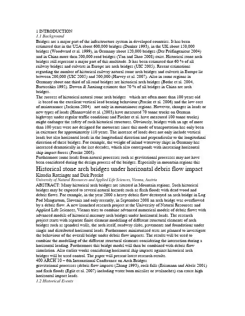
1 INTRODUCTION1.1 BackgroundBridges are a major part of the infrastructure system in developed countries. It has been estimated that in the USA about 600,000 bridges (Dunker 1993), in the UK about 150,000 bridges (Woodward et al. 1999), in Germany about 120,000 bridges (Der Prüfingenieur 2004) and in China more then 500,000 road bridges (Yan and Shao 2008) exist. Historical stone arch bridges still represent a major part of this multitude. It has been estimated that 60 % of all railway bridges and culverts in Europe are arch bridges (UIC 2005). Recent estimations regarding the number of historical railway natural stone arch bridges and culverts in Europe lie between 200,000 (UIC 2005) and 500,000 (Harvey et al. 2007). Also in some regions in Germany about one third of all road bridges are historical arch bridges (Bothe et al. 2004, Bartuschka 1995). Dawen & Jinxiang estimate that 70 % of all bridges in China are arch bridges.The success of historical natural stone arch bridges - which are often more than 100 years old- is based on the excellent vertical load bearing behaviour (Proske et al. 2006) and the low cost of maintenance (Jackson 2004) - not only in mountainous regions. However, changes in loads or new types of loads (Hannawald et al. (2003) have measured 70 tonne trucks on German highways under regular traffic conditions and Pircher et al. have measured 100 tonne trucks) might endanger the safety of such historical structures. Obviously, bridges with an age of more than 100 years were not designed for motorcars since this mode of transportation has only been in existence for approximately 110 years. The increase of loads does not only include vertical loads but also horizontal loads in the longitudinal direction and perpendicular to the longitudinal direction of these bridges. For example, the weight of inland waterway ships in Germany has increased dramatically in the last decades, which also corresponds with increasing horizontal ship impact forces (Proske 2003).Furthermore some loads from natural processes such as gravitational processes may not have been considered during the design process of the bridges. Especially in mountain regions this Historical stone arch bridges under horizontal debris flow impact Klaudia Ratzinger and Dirk ProskeUniversity of Natural Resources and Applied Life Sciences, Vienna, AustriaABSTRACT: Many historical arch bridges are situated in Mountain regions. Such historical bridges may be exposed to several natural hazards such as flash floods with dead wood and debris flows. For example, in the year 2000 a heavy debris flow destroyed an arch bridge in Log Pod Mangartom, Slovenia and only recently, in September 2008 an arch bridge was overflowed by a debris flow. A new launched research project at the University of Natural Resources and Applied Life Sciences, Vienna tries to combine advanced numerical models of debris flows with advanced models of historical masonry arch bridges under horizontal loads. The research project starts with separate finite element modelling of different structural elements of arch bridges such as spandrel walls, the arch itself, roadway slabs, pavements and foundations under single and distributed horizontal loads. Furthermore miniaturized tests are planned to investigate the behaviour of the overall bridge under debris flow impacts. The results will be used to combine the modelling of the different structural elements considering the interaction during a horizontal loading. Furthermore this bridge model will then be combined with debris flow simulation. Also earlier works considering horizontal ship impacts against historical arch bridges will be used control. The paper will present latest research results.400 ARCH’10 – 6th International Conference on Arch Bridgesgravitational processes (debris flow impacts (Zhang 1993), rock falls (Erismann and Abele 2001) and flash floods (Eglit et al. 2007) including water born missiles or avalanches) can cause high horizontal impact loads.1.2 Historical EventsIn the year 2000, a debris flow destroyed two bridges in Log Pod Mangartom, Slovenia, one of them was a historical arch bridge. In October 2007 the historical arch bridge in Beniarbeig, Spain was destroyed by a flash flood. Similarly the Pöppelmann arch bridge in Grimma, Germany was destroyed in 2002, in 2007 a farm track and public footpath arch bridge over the River Devon collapsed.Figure 1: Debris flow impact at the Lattenbach (Proske & Hübl, 2007)Fig.1 shows an example of the historical arch bridge at the Lattenbach, before and after a debris flow event, where the bridge is nearly completely filled with debris.Due to far too expensive solutions or not applicable methods for historical arch bridges it would be very useful if models were available to estimate the load bearing capacity of historical masonry arch bridges for horizontal loads perpendicular to the longitudinal direction.Since intensive research was carried out for the development of models dealing with vertical loads for historical arch bridges, there is an unsurprising lack of models capable for horizontal impact forces against the superstructure. This might be mainly based on the assumption that horizontal loads are not of major concern for this bridge type due to the great death load of such bridges.The goal of this investigation is the development of engineering models describing the behaviour of historical natural stone arch bridges under horizontal forces, mainly debris flow impacts, focused strongly on the behaviour of the superstructure and based on numerical simulations using discrete element models and finite element models.2 INNOVATIVE ASPECT AND GOALS2.1 Innovative AspectsThe conservation of historical arch bridges is not only an issue of the preservation of cultural heritage but is also an economic issue since the number of historical bridges in developed countries is huge (Proske 2009). Compared to vertical load cases no models currently exist for horizontal loads perpendicular to the longitudinal direction. It is therefore required to develop new models dealing with these capacious horizontal loads which include all types of gravitational hazards like avalanches, debris flow, rock falls or flood borne missiles or impacts from modes of transportation. First works related to the development of debris flow design impact forces and the behaviour of arch bridges under such an impact have started already 2007 at the Institute of Alpine Mountain Risk Engineering at the University of Natural Resources and Applied Life Sciences, Vienna (see Fig.2)Klaudia Ratzinger and Dirk Proske 401Figure 2 : Examples of the structural behaviour under impacts (left against the pier, right against the arch itself) (Proske and Hübl 2007)This investigation and its results regarding debris flow impact will flow into the development of the new Austrian code of practice Ö-Norm 24801 for the design of structures exposed to debris flow impacts as well.2.2 GoalTo develop load bearing behavior models of historical natural stone arch bridges under horizontal loads perpendicular to the longitudinal direction, a realistic model of debris flow against solid structures has to be implemented indifferent programs. Separate finite element modelling of different structural elements of arch bridges such as spandrel walls, the arch itself, roadway slabs, pavements and foundations under single and distributed horizontal loads are part of this investigation. Furthermore miniaturized tests are part of the project to investigate the behaviour of the overall bridge under debris flow impacts. The results will be used to combine the modelling of the different structural elements considering the interaction during a horizontal loading. Furthermore this bridge model will then be combined with debris flow simulation. Also earlier works considering horizontal ship impacts against historical arch bridges will be used. Therefore three models of historical arch bridges are developed:(1) Discrete element program model (PFC),(2) Explicit finite difference program model (FLAC),(3) Finite element program model (ANSYS, ATENA).The first and second models are developed to simulate an overall debris flow impact scenario, whereas the third model is used to investigate details, such as single force against a spandrel wall, single force against parapets, friction at the arch, single impact force against the arch. Results from the impact simulation against the superstructure should give an answer, whether the complete process can be separated into forces acting on the bridge. This reference force (force-time-function) will then be applied on the finite element models.The numerical modelling will be accompanied by testing to permit validation of the models. The tests will be carried out as miniaturized tests (scale about 1:20…50). Already miniaturized tests of the impact of debris flows against debris flow barriers were already carried out at the Institute of Mountain Risk Engineering (Proske et al. 2008, Hübl & Holzinger 2003,Fig.3). Based on this experience, miniaturized arch bridges (span about 40 to 50 cm) will be constructed and investigated. Also single parts of the arch structure will be investigated in testing machines, such as behaviour of a pure arch under a horizontal load. Since the machine cannot be turned, force redirection mechanisms will be used to allow the application of a standard compression test machine from the University of Natural Resources and Applied Life Sciences, Vienna.402 ARCH’10 – 6th International Conference on Arch BridgesFigure 3 : Side view and view from above of the used debris flow impact measurement test set-up (Hübl & Holzinger 2003)3 CALCULATIONS3.1 Discrete element methodsDiscrete element modeling can be done by usingPFC3D (Particle Flow Code 3D) which is used in analysis, testing and research in any field where the interaction of many discrete objects exhibiting large-strain and/or fracturing is required. By using the program PFC3D, materials can be modeled as either bonded (cemented) or granular assemblies of particle s.3.2 Finite element methodsThe finite element method (FEM) is one of the most powerful computer methods for solving partial differential equations applied on complex shapes and with complex boundary conditions.A mesh made of a complex system of points is programmed containing material and structural properties defining the reaction of the structure to certain loading conditions. Nodes are assigned at a certain density throughout the material depending on the anticipated stress levels of a certain area.Two types of analysis are commonly used: 2-D modelling and 3-D modelling. 2-D modelling allows the analysis to be run on a normal computer but tends to yield less accurate results whereas 3-D modelling shows more accurate results.For this investigation two FEM programs are used:(1) ANSYS(2) ATENAANSYS is the leading finite element analysis package for numerically solving a wide varietyof mechanical problems in 2D and 3D. By using ANSYS, the analysis can be done linear and non-linear, is applicable to static and dynamic structural analysis, heat transfer and fluid problems as well as acoustic and electromagnetic problems.The ATENA program is determined for nonlinear finite element analysis of structures, offers tools specially designed for computer simulation of concrete and reinforced concrete structural behaviour. Moreover, structures from other materials, such as soils, metals etc. can be treated as well.In the first step finite element methods are used to simulate the behaviour of historical natural stone arch bridges under an impact. Required data for the debris flow models are taken from the database of the Institute of Mountain Risk Engineering as well from the Austrian RailwayService (ÖBB).Klaudia Ratzinger and Dirk Proske 403The basic requirements for an appropriate assessment of stone arch bridges are:(1) Choice of a realistic calculation model(2) Consideration of geometrical and material nonlinearities(3) Using applicable material models for masonry(4) Adapted evidence based on the chosen material models.Therefore, a simplified arch bridge model with various lengths (L), rising of the vault (r) and thickness of the stone arch (t) was chosen (Fig.4) – first by using a two-dimensional model –with the purpose to investigate the importance of geometrical properties to their structural performance and to demonstrate different results. Further models are in process and will be implemented in the FEM programs as well.Figure 4 : FE model of a simplified arch bridge (Becke, 2005)4 CONCLUSIONSThis research project launched by the University of Natural Resources and Applied Life Sciences, Vienna combines advanced numerical models of debris flows with advanced models of historical masonry arch bridges under horizontal loads. It started with the implementation of separate finite element modelling of different structural elements of arch bridges. Furthermore miniaturized tests will be done in 2010 to investigate the behaviour of the overall bridge under debris flow impacts. The results will be used to combine the modelling of the different structural elements considering the interaction during a horizontal loading and the bridge model will be combined with debris flow simulation.Last but not least recommendation values for such bridge types should be given by this investigation that may include further formulas considering for example the adaptation of masonry stiffness or strength values.1介绍1.1背景桥梁是发达国家的基础设施系统的一个主要部分。
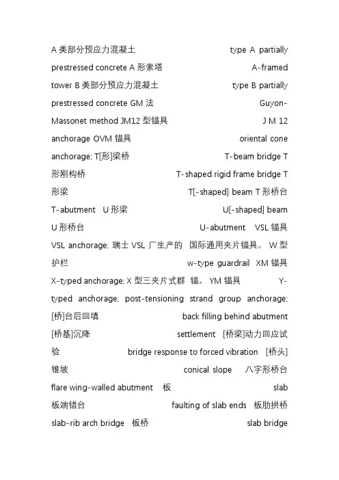
A类部分预应力混凝土 type A partially prestressed concrete A形索塔 A-framed tower B类部分预应力混凝土 type B partially prestressed concrete GM 法 Guyon-Massonet method JM12型锚具J M 12 anchorage OVM锚具 oriental cone anchorage; T[形]梁桥 T-beam bridge T形刚构桥 T-shaped rigid frame bridge T形梁T[-shaped] beam T形桥台 T-abutment U形梁U[-shaped] beam U形桥台 U-abutment VSL 锚具 VSL anchorage; 瑞士VSL 厂生产的国际通用夹片锚具。
W型护栏 w-type guardrail XM锚具 X-typed anchorage; X型三夹片式群锚。
YM锚具 Y-typed anchorage, post-tensioning strand group anchorage; [桥]台后回填 back filling behind abutment [桥基]沉降 settlement [桥梁]动力回应试验 bridge response to forced vibration [桥头]锥坡 conical slope 八字形桥台flare wing-walled abutment 板 slab 板端错台faulting of slab ends 板肋拱桥slab-rib arch bridge 板桥 slab bridge 板式橡胶支座 laminated rubber bearing 板体断裂slab rupture 板体翘曲 slab warping 板体温度翘曲应力 slab stress due to thermal warping 板桩sheet pile 板桩围堰 sheet pile cofferdam 便桥detour bridge 标准车辆荷载standard truck loading 波纹钢桥面 corrugated steel deck 波纹管涵 corrugated-metal pipe culvert 波形梁护栏 corrugated beam barrier 超载预压surcharge preloading 车道lane 车道分布 lane distribution 车道荷载lane load 车间净距 vehicular gap 沉管灌注桩 tube-sinking cast-in-situ pile沉降差 differential settlement 沉井基础open caisson foundation 沉井刃脚 caisson cutting edge 冲击系数 impact factor; 承台bearing platform, pile cap 冲刷 scouring erosion 搭接钢板接缝 lapped steel plate joint 打入桩driven pile 打桩pile driving 搭接钢板接缝 lapped steel plate joint 打入桩driven pile 打桩pile driving 大跨径桥 long span bridge 单铰拱桥 single-hinged arch bridge 单室箱梁single cell box girder 单索面斜拉桥 single plane cable stayed bridge 单向板 one-way slab 单向推力墩 single direction thrusted pier 单柱式[桥]墩 single-columned pier, single shaft pier 单桩 individual pile, single pile 单桩承载力bearing capacity of pile 弹性梁支承法 elastic supported beam method 弹性模量 modulus of elasticity 挡土墙 retaining wall 地震荷载earthquake load seismic force; 又称“地震力”。

西南交通大学本科毕业设计(论文)外文资料翻译年级:学号:姓名:专业:指导老师:2013年 6 月外文资料原文:13Box girders13.1 GeneralThe box girder is the most flexible bridge deck form。
It can cover a range of spans from25 m up to the largest non—suspended concrete decks built, of the order of 300 m。
Single box girders may also carry decks up to 30 m wide。
For the longer span beams, beyond about 50 m,they are practically the only feasible deck section. For the shorter spans they are in competition with most of the other deck types discussed in this book.The advantages of the box form are principally its high structural efficiency (5.4),which minimises the prestress force required to resist a given bending moment,and its great torsional strength with the capacity this gives to re—centre eccentric live loads,minimising the prestress required to carry them。
The box form lends itself to many of the highly productive methods of bridge construction that have been progressively refined over the last 50 years,such as precast segmental construction with or without epoxy resin in the joints,balanced cantilever erection either cast in—situ or coupled with precast segmental construction, and incremental launching (Chapter 15)。
建筑土木工程外文翻译外文文献英文文献混凝土桥梁Concrete BridgesConcrete is the most-used construction material for bridges in the United States, and indeed in the world. The application of prestressing to bridges has grown rapidly and steadily, beginning in 1949 with high-strength steel wires in the Walnut Lane Bridge in Philadelphia, Pennsylvania. According to the Federal Highway Administration’s 1994 National Bridge Inventory data, from 1950 to the early 1990s, prestressed concrete bridges have gone from being virtually nonexistent to representing over 50 percent of all bridges built in the United States.Prestressing has also played an important role in extending the span capability of concrete bridges. By the late 1990s, spliced-girder spans reached a record 100 m (330 ft). Construction of segmental concrete bridges began in the United States in 1974.Curretly, close to 200 segmental concrete bridges have been built or are under construction, with spans up to 240 m (800 ft).Late in the 1970s, cable-stayed construction raised the bar for concrete bridges. By 1982, the Sunshine Skyway Bridge in Tampa, Florida, had set a new record for concrete bridges, with a main span of 365 m (1,200 ft). The next year, the Dames Point Bridge in Jacksonville, Florida, extended the record to 400 m (1,300 ft).HIGH-PERFORMANCE CONCRETECompressive StrengthFor many years the design of precast prestressed concrete girders was based on concrete compressive strengths of 34 to 41 MPa (5,000 to 6,000 psi). This strength level served the industrywell and provided the basis for establishing the prestressed concrete bridge industry in the United States. In the 1990s the industry began to utilize higher concrete compressive strengths in design, and at the start of the new millennium the industry is poised to accept the use of concrete compressive strengths up to 70 MPa (10,000 psi).For the future, the industry needs to seek ways to effectively utilize even higher concrete compressive strengths. The ready-mixed concrete industry has been producing concretes with compressive strengths in excess of 70 MPa for over 20 years. Several demonstration projects have illustrated that strengths above 70 MPa can be achieved for prestressed concrete girders. Barriers need to be removed to allow the greater use of these materials. At the same time, owners, designers, contractors, and fabricators need to be more receptive to the use of higher-compressive-strength concretes.DurabilityHigh-performance concrete (HPC) can be specified as high compressive strength (e.g., in prestressed girders) or as conventional compressive strength with improved durability (e.g., in cast-in-place bridge decks and substructures). There is a need to develop a better understanding of all the parameters that affect durability, such asresistance to chemical, electrochemical, and environmental mechanisms that attack the integrity of the material. Significant differences might occur in the long-term durability of adjacent twin structures constructed at the same time using identical materials. This reveals our lack of understanding and control of the parameters that affect durability. NEW MATERIALS Concrete design specifications have in the past focusedprimarily on the compressive strength. Concrete is slowly moving toward an engineered material whose direct performance can be altered by the designer. Material properties such as permeability, ductility, freeze-thaw resistance, durability, abrasion resistance, reactivity, and strength will be specified. The HPC initiative has gone a long way in promoting these specifications, but much more can be done. Additives, such a fibers or chemicals, can significantly alter the basic properties of concrete. Other new materials, such as fiber-reinforced polymer composites, nonmetallic reinforcement (glass fiber-reinforced and carbon fiber-reinforced plastic, etc.), new metallic reinforcements, or high-strength steel reinforcement can also be used to enhance the performance of what is considered to be a traditional material. Higher-strength reinforcement could be particularly useful when coupled with high-strength concrete. As our natural resources diminish, alternative aggregate sources (e.g., recycled aggregate) and further replacement of cementitious materials with recycled products are being examined. Highly reactive cements and reactive aggregates will be concerns of the past as new materials with long-term durability become commonplace.New materials will also find increasing demand in repair and retrofitting. As the bridge inventory continues to get older, increasing the usable life of structures will become critical. Some innovative materials, although not economical for complete bridges, will find their niche in retrofit and repair.OPTIMIZED SECTIONSIn early applications of prestressed concrete to bridges, designers developed their own ideas of the best girder sections. The result is that each contractor used slightly different girder shapes. It was too expensive to design custom girders for eachproject.As a result, representatives for the Bureau of Public Roads (now FHWA), the American Association of State Highway Officials (AASHO) (now AASHTO), and the Prestressed Concrete Institute (PCI) began work to standardize bridge girder sections. The AASHTO-PCI standard girder sections Types I through IV were developed in the late 1950s and Types V and VI in the early 1960s. There is no doubt that standardization of girders has simplified design, has led to wider utilization of prestressed concrete for bridges, and, more importantly, has led to reduction in cost.With advancements in the technology of prestressed concrete design and construction, numerous states started to refine their designs and to develop their own standard sections. As a result, in the late 1970s, FHWA sponsored a study to evaluate existing standard girder sections and determine the most efficient girders. This study concluded that bulb-tees were the most efficient sections. These sections could lead to reduction in girder weights of up to 35 percent compared with the AASHTO Type VI and cost savings up to 17 percent compared with the AASHTO-PCI girders, for equal spancapability. On the basis of the FHWA study, PCI developed the PCI bulb-tee standard, which was endorsed by bridge engineers at the 1987 AASHTO annual meeting. Subsequently, the PCI bulb-tee cross section was adopted in several states. In addition, similar cross sections were developed and adopted in Florida, Nebraska, and the New England states. These cross sections are also cost-effective with high-strength concretes for span lengths up to about 60 m (200 ft).SPLICED GIRDERSSpliced concrete I-girder bridges are cost-effective for a spanrange of 35 to 90 m (120 to 300 ft). Other shapes besides I-girders include U, T, and rectangular girders, although the dominant shape in applications to date has been the I-girder, primarily because of its relatively low cost. A feature of spliced bridges is the flexibility they provide in selection of span length, number and locations of piers, segment lengths, and splice locations. Spliced girders have the ability to adapt to curved superstructure alignments by utilizing short segment lengths and accommodating the change in direction in the cast-in-place joints. Continuity in spliced girder bridges can be achieved through full-length posttensioning, conventional reinforcement in the deck, high-strength threaded bar splicing, or pretensioned strand splicing, although the great majority of applications utilize full-length posttensioning. The availability of concrete compressive strengths higher than the traditional 34 MPa (5,000 psi) significantly improves the economy of spliced girder designs, in which high flexural and shear stresses are concentrated near the piers. Development of standardized haunched girder pier segments is needed for efficiency in negative-moment zones. Currently, the segment shapes vary from a gradually thickening bottom flange to a curved haunch with constant-sized bottom flange and variable web depth.SEGMENTAL BRIDGESSegmental concrete bridges have become an established type of construction for highway and transit projects on constrained sites. Typical applications include transit systems over existing urban streets and highways, reconstruction of existing interchanges and bridges under traffic, or projects that cross environmentally sensitive sites. In addition, segmental construction has been proved to be appropriate for large-scale,repetitive bridges such as long waterway crossings or urban freeway viaducts or where the aesthetics of the project are particularly important.Current developments suggest that segmental construction will be used on a larger number of projects in the future. Standard cross sections have been developed to allow for wider application of this construction method to smaller-scale projects. Surveys of existing segmental bridges have demonstrated the durability of this structure type and suggest that additional increases in design life are possible with the use of HPC. Segmental bridges with concrete strengths of 55 MPa (8,000 psi) or more have been constructed over the past 5 years. Erection with overhead equipment has extended applications to more congested urban areas. Use of prestressed composite steel and concrete in bridges reduces the dead weight of the superstructure and offers increased span lengths.LOAD RATING OF EXISTING BRIDGESExisting bridges are currently evaluated by maintaining agencies using working stress, load factor, or load testing methods. Each method gives different results, for several reasons. In order to get national consistency, FHWA requests that all states report bridge ratings using the load factor method. However, the new AASHTO Load and Resistance Factor Design (LRFD) bridge design specifications are different from load factor method. A discrepancy exists, therefore, between bridge design and bridge rating.A draft of a manual on condition evaluation of bridges, currently under development for AASHTO, has specifications for load and resistance factor rating of bridges. These specifications represent a significant change from existing ones. States will beasked to compare current load ratings with the LRFD load ratings using a sampling of bridges over the next year, and adjustments will be proposed. The revised specifications and corresponding evaluation guidelines should complete the LRFD cycle of design, construction, and evaluation for the nation's bridges.LIFE-CYCLE COST ANALYSISThe goal of design and management of highway bridges is to determine and implement the best possible strategy that ensures an adequate level of reliability at the lowest possible life-cycle cost. Several recent regulatory requirements call for consideration of life-cycle cost analysis for bridge infrastructure investments. Thus far, however, the integration of life-cycle cost analysis with structural reliability analysis has been limited. There is no accepted methodology for developing criteria for life-cycle cost design and analysis of new and existing bridges. Issues such as target reliability level, whole-life performance assessment rules, and optimum inspection-repair-replacement strategies for bridges must be analyzed and resolved from a life-cycle cost perspective. T o achieve this design and management goal, state departments of transportation must begin to collect the data needed to determine bridge life-cycle costs in a systematic manner. The data must include inspection, maintenance, repair, and rehabilitation expenditures and the timing of these expenditures. At present, selected state departments of transportation are considering life-cycle cost methodologies and software with the goal of developing a standard method for assessing the cost-effectiveness of concrete bridges. DECKS Cast-in-place (CIP) deck slabs are the predominant method of deck construction in the United States. Their main advantage is the ability to provide a smooth riding surface by field-adjustment of the roadway profile during concrete placement. In recent years automation of concrete placement and finishing has made this system cost-effective. However, CIP slabs have disadvantages that include excessive differential shrinkage with the supporting beams and slow construction. Recent innovations in bridge decks have focused on improvement to current practice with CIP decks and development of alternative systems that are cost-competitive, fast to construct, and durable. Focus has been on developing mixes and curing methods that produce performance characteristics such as freeze-thaw resistance, high abrasion resistance, low stiffness, and low shrinkage, rather than high strength. Full-depth precast panels have the advantages of significant reduction of shrinkage effects and increased construction speed and have been used in states with high traffic volumes for deck replacement projects. NCHRP Report 407 on rapid replacement of bridge decks has provided a proposed full-depth panel system with panels pretensioned in the transverse direction and posttensioned in the longitudinaldirection.Several states use stay-in-place (SIP) precast prestressed panels combined with CIP topping for new structures as well as for deck replacement. This system is cost-competitive with CIP decks. The SIP panels act as forms for the topping concrete and also as part of the structural depth of the deck. This system can significantly reduce construction time because field forming is only needed for the exterior girder overhangs. The SIP panel system suffers from reflective cracking, which commonly appears over the panel-to-panel joints. A modified SIP precast panel system has recently been developed in NCHRP Project 12-41.SUBSTRUCTURESContinuity has increasingly been used for precast concrete bridges. For bridges with total lengths less than 300 m (1,000 ft), integral bridge abutments and integral diaphragms at piers allow for simplicity in construction and eliminate the need for maintenance-prone expansion joints. Although the majority of bridge substructure components continue to be constructed from reinforced concrete, prestressing has been increasingly used. Prestressed bents allow for longer spans, improving durability and aesthetics and reducing conflicts with streets and utilities in urban areas. Prestressed concrete bents are also being used for structural steel bridges to reduce the overall structure depth and increase vertical clearance under bridges. Precast construction has been increasingly used for concrete bridge substructure components. Segmental hollow box piers and precast pier caps allow for rapid construction and reduced dead loads on the foundations. Precasting also enables the use of more complex forms and textures in substructure components, improving the aesthetics of bridges in urban and rural areas. RETAINING WALLSThe design of earth retaining structures has changed dramatically during the last century. Retaining wall design has evolved from short stone gravity sections to concrete structures integrating new materials such as geosynthetic soil reinforcements and high-strength tie-back soil anchors.The design of retaining structures has evolved into three distinct areas. The first is the traditional gravity design using the mass of the soil and the wall to resist sliding and overturning forces. The second is referred to as mechanically stabilized earth design. This method uses the backfill soil exclusively as the mass to resist the soil forces by engaging the soil using steel orpolymeric soil reinforcements. A third design method is the tie-back soil or rock anchor design, which uses discrete high-strength rods or cables that are drilled deep into the soil behind the wall to provide a dead anchorage to resist the soil forces.A major advancement in the evolution of earth retaining structures has been the proliferation of innovative proprietary retaining walls. Many companies have developed modular wall designs that are highly adaptable to many design scenarios. The innovative designs combined with the modular standard sections and panels have led to a significant decrease in the cost for retaining walls. Much research has been done to verify the structural integrity of these systems, and many states have embraced these technologies. RESEARCHThe primary objectives for concrete bridge research in the 21st century are to develop and test new materials that will enable lighter, longer, more economical, and more durable concrete bridge structures and to transfer this technology into the hands of the bridge designers for application. The HPCs developed toward the end of the 20th century would be enhanced by development of more durable reinforcement. In addition, higher-strength prestressing reinforcement could more effectively utilize the achievable higher concrete strengths. Lower-relaxation steel could benefit anchor zones. Also, posttensioning tendons and cable-stays could be better designed for eventual repair and replacement. As our natural resources diminish, the investigation of the use of recycled materials is as important as the research on new materials.The development of more efficient structural sections to better utilize the performance characteristics of new materials is important. In addition, more research is required in the areas ofdeck replacement panels, continuity regions of spliced girder sections, and safe,durable, cost-effective retaining wall structures.Research in the areas of design and evaluation will continue into the next millennium.The use of HPC will be facilitated by the removal of the implied strength limitation of 70 MPa (10.0 ksi) and other barriers in the LRFD bridge design specifications. As our nation’s infrastructure continues to age and as the vehicle loads continue to increase, it is important to better evaluate the capacity of existing structures and to develop effective retrofitting techniques. Improved quantification of bridge system reliability is expected through the calibration of system factors to assess the member capacities as a function of the level of redundancy. Data regarding inspection, maintenance, repair, and rehabilitation expenditures and their timing must be systematically collected and evaluated to develop better methods of assessing cost-effectiveness of concrete bridges. Performance-based seismic design methods will require a higher level of computing and better analysis tools.In both new and existing structures, it is important to be able to monitor the “health” of these structures through the development of instrumentation (e.g., fiber optics) to determine the state of stresses and corrosion in the members.CONCLUSIONIntroduced into the United States in 1949, prestressed concrete bridges today represent over 50 percent of all bridges built. This increase has resulted from advancements in design and analysis procedures and the development of new bridge systems and improved materials.The year 2000 sets the stage for even greater advancements. An exciting future lies ahead for concrete bridges!混凝土桥梁在美国甚至在世界桥梁上,混凝土是最常用的建设材料。

中英文对照外文翻译(文档含英文原文和中文翻译)Bridge research in EuropeA brief outline is given of the development of the European Union, together with the research platform in Europe. The special case of post-tensioned bridges in the UK is discussed. In order to illustrate the type of European research being undertaken, an example is given from the University of Edinburgh portfolio: relating to the identification of voids in post-tensioned concrete bridges using digital impulse radar.IntroductionThe challenge in any research arena is to harness the findings of different research groups to identify a coherent mass of data, which enables research and practice to be better focused. A particular challenge exists with respect to Europe where language barriers are inevitably very significant. The European Community was formed in the 1960s based upon a political will within continental Europe to avoid the European civil wars, which developed into World War 2 from 1939 to 1945. The strong political motivation formed the original community of which Britain was not a member. Many of the continental countries saw Britain’s interest as being purelyeconomic. The 1970s saw Britain joining what was then the European Economic Community (EEC) and the 1990s has seen the widening of the community to a European Union, EU, with certain political goals together with the objective of a common European currency.Notwithstanding these financial and political developments, civil engineering and bridge engineering in particular have found great difficulty in forming any kind of common thread. Indeed the educational systems for University training are quite different between Britain and the European continental countries. The formation of the EU funding schemes —e.g. Socrates, Brite Euram and other programs have helped significantly. The Socrates scheme is based upon the exchange of students between Universities in different member states. The Brite Euram scheme has involved technical research grants given to consortia of academics and industrial partners within a number of the states— a Brite Euram bid would normally be led by an industrialist.In terms of dissemination of knowledge, two quite different strands appear to have emerged. The UK and the USA have concentrated primarily upon disseminating basic research in refereed journal publications: ASCE, ICE and other journals. Whereas the continental Europeans have frequently disseminated basic research at conferences where the circulation of the proceedings is restricted.Additionally, language barriers have proved to be very difficult to break down. In countries where English is a strong second language there has been enthusiastic participation in international conferences based within continental Europe —e.g. Germany, Italy, Belgium, The Netherlands and Switzerland. However, countries where English is not a strong second language have been hesitant participants }—e.g. France.European researchExamples of research relating to bridges in Europe can be divided into three types of structure:Masonry arch bridgesBritain has the largest stock of masonry arch bridges. In certain regions of the UK up to 60% of the road bridges are historic stone masonry arch bridges originally constructed for horse drawn traffic. This is less common in other parts of Europe as many of these bridges were destroyed during World War 2.Concrete bridgesA large stock of concrete bridges was constructed during the 1950s, 1960s and 1970s. At the time, these structures were seen as maintenance free. Europe also has a large number of post-tensioned concrete bridges with steel tendon ducts preventing radar inspection. This is a particular problem in France and the UK.Steel bridgesSteel bridges went out of fashion in the UK due to their need for maintenance as perceived in the 1960s and 1970s. However, they have been used for long span and rail bridges, and they are now returning to fashion for motorway widening schemes in the UK.Research activity in EuropeIt gives an indication certain areas of expertise and work being undertaken in Europe, but is by no means exhaustive.In order to illustrate the type of European research being undertaken, an example is given from the University of Edinburgh portfolio. The example relates to the identification of voids in post-tensioned concrete bridges, using digital impulse radar.Post-tensioned concrete rail bridge analysisOve Arup and Partners carried out an inspection and assessment of the superstructure of a 160 m long post-tensioned, segmental railway bridge in Manchester to determine its load-carrying capacity prior to a transfer of ownership, for use in the Metrolink light rail system..Particular attention was paid to the integrity of its post-tensioned steel elements. Physical inspection, non-destructive radar testing and other exploratory methods were used to investigate for possible weaknesses in the bridge.Since the sudden collapse of Ynys-y-Gwas Bridge in Wales, UK in 1985, there has been concern about the long-term integrity of segmental, post-tensioned concrete bridges which may b e prone to ‘brittle’ failure without warning. The corrosion protection of the post-tensioned steel cables, where they pass through joints between the segments, has been identified as a major factor affecting the long-term durability and consequent strength of this type of bridge. The identification of voids in grouted tendon ducts at vulnerable positions is recognized as an important step in the detection of such corrosion.Description of bridgeGeneral arrangementBesses o’ th’ Barn Bridge is a 160 m long, three span, segmental, post-tensionedconcrete railway bridge built in 1969. The main span of 90 m crosses over both the M62 motorway and A665 Bury to Prestwick Road. Minimum headroom is 5.18 m from the A665 and the M62 is cleared by approx 12.5 m.The superstructure consists of a central hollow trapezoidal concrete box section 6.7 m high and 4 m wide. The majority of the south and central spans are constructed using 1.27 m long pre-cast concrete trapezoidal box units, post-tensioned together. This box section supports the in site concrete transverse cantilever slabs at bottom flange level, which carry the rail tracks and ballast.The center and south span sections are of post-tensioned construction. These post-tensioned sections have five types of pre-stressing:1. Longitudinal tendons in grouted ducts within the top and bottom flanges.2. Longitudinal internal draped tendons located alongside the webs. These are deflected at internal diaphragm positions and are encased in in site concrete.3. Longitudinal macalloy bars in the transverse cantilever slabs in the central span .4. Vertical macalloy bars in the 229 mm wide webs to enhance shear capacity.5. Transverse macalloy bars through the bottom flange to support the transverse cantilever slabs.Segmental constructionThe pre-cast segmental system of construction used for the south and center span sections was an alternative method proposed by the contractor. Current thinking suggests that such a form of construction can lead to ‘brittle’ failure of the ent ire structure without warning due to corrosion of tendons across a construction joint,The original design concept had been for in site concrete construction.Inspection and assessmentInspectionInspection work was undertaken in a number of phases and was linked with the testing required for the structure. The initial inspections recorded a number of visible problems including:Defective waterproofing on the exposed surface of the top flange.Water trapped in the internal space of the hollow box with depths up to 300 mm.Various drainage problems at joints and abutments.Longitudinal cracking of the exposed soffit of the central span.Longitudinal cracking on sides of the top flange of the pre-stressed sections.Widespread sapling on some in site concrete surfaces with exposed rusting reinforcement.AssessmentThe subject of an earlier paper, the objectives of the assessment were:Estimate the present load-carrying capacity.Identify any structural deficiencies in the original design.Determine reasons for existing problems identified by the inspection.Conclusion to the inspection and assessmentFollowing the inspection and the analytical assessment one major element of doubt still existed. This concerned the condition of the embedded pre-stressing wires, strands, cables or bars. For the purpose of structural analysis these elements、had been assumed to be sound. However, due to the very high forces involved,、a risk to the structure, caused by corrosion to these primary elements, was identified.The initial recommendations which completed the first phase of the assessment were:1. Carry out detailed material testing to determine the condition of hidden structural elements, in particularthe grouted post-tensioned steel cables.2. Conduct concrete durability tests.3. Undertake repairs to defective waterproofing and surface defects in concrete.Testing proceduresNon-destructi v e radar testingDuring the first phase investigation at a joint between pre-cast deck segments the observation of a void in a post-tensioned cable duct gave rise to serious concern about corrosion and the integrity of the pre-stress. However, the extent of this problem was extremely difficult to determine. The bridge contains 93 joints with an average of 24 cables passing through each joint, i.e. there were approx. 2200 positions where investigations could be carried out. A typical section through such a joint is that the 24 draped tendons within the spine did not give rise to concern because these were protected by in site concrete poured without joints after the cables had been stressed.As it was clearly impractical to consider physically exposing all tendon/joint intersections, radar was used to investigate a large numbers of tendons and hence locate duct voids within a modest timescale. It was fortunate that the corrugated steel ducts around the tendons were discontinuous through the joints which allowed theradar to detect the tendons and voids. The problem, however, was still highly complex due to the high density of other steel elements which could interfere with the radar signals and the fact that the area of interest was at most 102 mm wide and embedded between 150 mm and 800 mm deep in thick concrete slabs.Trial radar investigations.Three companies were invited to visit the bridge and conduct a trial investigation. One company decided not to proceed. The remaining two were given 2 weeks to mobilize, test and report. Their results were then compared with physical explorations.To make the comparisons, observation holes were drilled vertically downwards into the ducts at a selection of 10 locations which included several where voids were predicted and several where the ducts were predicted to be fully grouted. A 25-mm diameter hole was required in order to facilitate use of the chosen horoscope. The results from the University of Edinburgh yielded an accuracy of around 60%.Main radar sur v ey, horoscope verification of v oids.Having completed a radar survey of the total structure, a baroscopic was then used to investigate all predicted voids and in more than 60% of cases this gave a clear confirmation of the radar findings. In several other cases some evidence of honeycombing in the in site stitch concrete above the duct was found.When viewing voids through the baroscopic, however, it proved impossible to determine their actual size or how far they extended along the tendon ducts although they only appeared to occupy less than the top 25% of the duct diameter. Most of these voids, in fact, were smaller than the diameter of the flexible baroscopic being used (approximately 9 mm) and were seen between the horizontal top surface of the grout and the curved upper limit of the duct. In a very few cases the tops of the pre-stressing strands were visible above the grout but no sign of any trapped water was seen. It was not possible, using the baroscopic, to see whether those cables were corroded.Digital radar testingThe test method involved exciting the joints using radio frequency radar antenna: 1 GHz, 900 MHz and 500 MHz. The highest frequency gives the highest resolution but has shallow depth penetration in the concrete. The lowest frequency gives the greatest depth penetration but yields lower resolution.The data collected on the radar sweeps were recorded on a GSSI SIR System 10.This system involves radar pulsing and recording. The data from the antenna is transformed from an analogue signal to a digital signal using a 16-bit analogue digital converter giving a very high resolution for subsequent data processing. The data is displayed on site on a high-resolution color monitor. Following visual inspection it is then stored digitally on a 2.3-gigabyte tape for subsequent analysis and signal processing. The tape first of all records a ‘header’ noting the digital radar settings together with the trace number prior to recording the actual data. When the data is played back, one is able to clearly identify all the relevant settings —making for accurate and reliable data reproduction.At particular locations along the traces, the trace was marked using a marker switch on the recording unit or the antenna.All the digital records were subsequently downloaded at the University’s NDT laboratory on to a micro-computer.(The raw data prior to processing consumed 35 megabytes of digital data.)Post-processing was undertaken using sophisticated signal processing software. Techniques available for the analysis include changing the color transform and changing the scales from linear to a skewed distribution in order to highlight、突出certain features. Also, the color transforms could be changed to highlight phase changes. In addition to these color transform facilities, sophisticated horizontal and vertical filtering procedures are available. Using a large screen monitor it is possible to display in split screens the raw data and the transformed processed data. Thus one is able to get an accurate indication of the processing which has taken place. The computer screen displays the time domain calibrations of the reflected signals on the vertical axis.A further facility of the software was the ability to display the individual radar pulses as time domain wiggle plots. This was a particularly valuable feature when looking at individual records in the vicinity of the tendons.Interpretation of findingsA full analysis of findings is given elsewhere, Essentially the digitized radar plots were transformed to color line scans and where double phase shifts were identified in the joints, then voiding was diagnosed.Conclusions1. An outline of the bridge research platform in Europe is given.2. The use of impulse radar has contributed considerably to the level of confidence in the assessment of the Besses o’ th’ Barn Rail Bridge.3. The radar investigations revealed extensive voiding within the post-tensioned cable ducts. However, no sign of corrosion on the stressing wires had been found except for the very first investigation.欧洲桥梁研究欧洲联盟共同的研究平台诞生于欧洲联盟。
桥梁英语词汇.doc实用标准文案下部结构substructure桥墩pier墩身pier body墩帽pier cap, pier coping台帽abutment cap, abutment coping盖梁bent cap又称“帽梁” 。
重力式 [桥 ] 墩 gravity pier实体 [桥 ]墩 solid pier空心 [桥 ]墩 hollow pier柱式 [桥 ]墩 column pier, shaft pier单柱式 [桥 ] 墩 single-columned pier, single shaft pier 双柱式[桥 ] 墩 two-columned pier, two shaft pier排架桩墩pile-bent pier丫形 [桥 ]墩 Y-shaped pier柔性墩flexible pier制动墩braking pier, abutment pier单向推力墩single direction thrusted pier 抗撞墩anti-collision pier锚墩anchor pier辅助墩auxiliary pier破冰体ice apron防震挡块anti-knock block, restrain block 桥台abutment台身abutment body前墙front wall又称“胸墙” 。
翼墙wing wall又称“耳墙” 。
U 形桥台U-abutment八字形桥台flare wing-walled abutment 一字形桥台head wall abutmentT 形桥台T-abutment箱形桥台box type abutment拱形桥台arched abutment重力式桥台gravity abutment埋置式桥台buried abutment扶壁式桥台counterfort abutment, buttressed abutment 衡重式桥台weight-balanced abutment锚碇板式桥台anchored bulkhead abutment支撑式桥台supported type abutment又称“轻型桥台” 。
Long and light——《Bridge design & engineering》Closure of the main span on the Sundoya Bridge in Norway is expected to take place in the first week after Easter. This graceful crossing, the second longest of its type in the world, is being built in situ using high performance concreteSundoya Bridge is situated in one of Norway's most scenic areas, only 100km south of the Arctic Circle. The 538m-long bridge spans Sundet, and when it is complete will provide a ferry-free road connection between Sundoya and the mainland. It is located some 35km west of the city of Mosjoen, close to highway 78 between Mosjoen and Sandnessjoen.It will be the second large bridge project connecting Alstenoya to the mainland, coming more than 12 years after the Helgeland Bridge was opened. The region is no stranger to world-record scale bridges ?the Helgeland Bridge's 425m long main span was the longest cable-stayed span in the world when it opened in 1992.Sundoya Bridge is divided into three spans; it has a main span of 298m and two side spans of 120m. The main span will be the second longest span in the world for a continuous post-tensioned cast in place box section concrete bridge.In terms of its design, consultant Dr Ing Aas-Jakobsen has followed a similar approach to that taken for the Raftsundet Bridge, opened in 1998, to which the Sundoya Bridge will almost be a twin. The two bridges have identical main spans, but Raftsundet has four spans as opposed to Sundoya's three. Contractor AS Anlegg, which is part of the joint venture building Sundoya, was also the contractor on the Raftsundet Bridge, and architect Boarch Arkitekter has also worked on the two schemes.In January 2001 the joint venture company AF Sundoybrua won the contract from client Statens Vegvesen to build the Sundoya Bridge. This joint venture consisted of the contractors Reinertsen Anlegg and NCC Construction.High performance concrete is central to the design of the bridge ?both normal weight HPC and lightweight HPC. Normal weight concrete, at approximately 2500kg/m3, is used for the 120m side spans, while lightweight concrete, which weighs in at about 1970kg/m3, is used for construction of the 298m main span. This enables construction to proceed using the balanced cantilever method.Local rock from Norway is used as the aggregate for the normal weight concrete, but the lightweight concrete required an imported solution. Normally the aggregate used for lightweight concrete in Europe is expanded clay or shale, but this material has high levels of absorption and for this reason, regulations prevent such concrete from being pumped.In order to address this, the contractor adopted a similar solution to that used on RaftsundetBridge ?importing Stalite aggregate from South Carolina in the USA. Stalite is produced through thermal expansion of high quality slate, and results in a lightweight aggregate that gives concrete of very high strength at low unit weights. Its low absorption of approximately 6% and high particle strength are two of the factors that allow Stalite to achieve high strength concrete in excess of 82.7MPa, the manufacturer says. The bondand compatibility of the aggregate with cement paste reduce micro-cracking and enhance durability, and its low absorption makes it easy to mix and pump.According to AF Sundoybrua quality manager Jan-Eirik Nilsskog, this material has given a very good result. It produces concrete that is easy to pour into the formwork and it gives a good surface finish, he says. It is being pumped some 120m along the bridge deck to the concreting position. Concrete is produced by a transportable mobile plant located only 1km from the bridge site. Constant monitoring of the concrete weight is necessary to ensure that the cantilevers are properly balanced. This is tested for each pour.The project began in January 2001 at Aker Verdal with the production of caissons for the pier bases. In May 2001 the two caissons were towed 500km north to the bridge site.The bridge is being poured in situ using special mobile construction equipment developed by NRS. The cycle for construction of each 5m wide bridge segment is a week, and two mobile units are being used on the Sundoya Bridge. These particular units were built for AS Anlegg to use on the Varodden Bridge in Kristiansand in Norway, and they have also been used by the same contractor on the Rafsundet Bridge. The design of the central part of the main span of the bridge is based on the use of lightweight concrete LC60 while other parts of the structure use the more standard type C65. Because of the aggressive marine environment, the quality of the concrete must be particularly good.The structure is a single cell, prestressed rectangular box girder, largely built using the travelling formwork system from NRS. The box width is 7m and its depth varies from 3m at the centre of the span to 14.5m over the piers. Close to the abutments, concrete of quality C25 will be used inside the box girder as ballast. In addition, the designers have included the necessary elements inside the box girder in order to allow the possible addition of post-tensioning cables in the future. The long-term behaviour of such large spans is not fully known, so the possibility that the main span may sag over time has to be taken into account. The width of the road is a constant 7.5m from the barrier on one side to that on the other, and the total width of the bridge is some 10.3m. There is a 2m wide footway included in the width of the structure.The pier shaft is formed with twin legs, which are hollow inside. The pier shafts incorporate permanent prestressing cables and they have a constant wall thickness and a width that varies parabolically over their height.Temporary tie-down piers are used to construct the bridge - they are located 35m into each 120m-long side span from the main piers. Each consists of an I-shaped shaft, which is tied down to the ground using rock anchors and connected to the box girder by means of prestressing cables. The purpose of these structural elements is to support the cantilever and prevent rotation in strong winds. Once the bridge superstructure is complete and the main pier prestressing is fully tensioned, the temporary tie-down pierswill be removed piece by piece.The location of the bridge, only about 100km south of the Arctic Circle, has meant that special measures have to be introduced to allow construction work to continue all year round. Apart from the obvious need to provide site lighting for much of the wintertime, the challenge of concreting in temperatures which can be as low as 0 C has to be overcome. Hot concrete is produced for the bridge ?sometimes up to 30 C and the formwork has to be insulated to keep the concrete warm. Electric heating cables are also used on the end of the previous pour to warm up the concrete before casting.Construction of the new bridge began in January 2000 and is expected to be complete in September this year. The construction of the cantilever started in summer last year and is due to be finished in April. When Bd&e went to press, the project was on schedule for opening to traffic in late autumn.Project TeamClient: Statens VegvesenContractor: AF Sundoybrua (AS Anlegg, NCC Construction)Consultant: Dr Ing Aas-JakobsenArchitect: Boarch Arkitekter超轻大跨度桥——Sundoya挪威的在Sundoya 桥上的主跨有望在复活节的后第一个星期望合龙. 它是一座大跨度的,在世界的它的同类型中第二长,建造在situ 的长大桥。
桥梁设计外文翻译文献(文档含中英文对照即英文原文和中文翻译) 原文:A Bridge For All CenturiesAn extremely long-and record setting-main span was designed for the second bridge to across the Panama Canal in order to meet the owner’s requirement that no piers be placed in the water.Because no disruption of canal traffic was permitted at any time,the cable-stayed bridge of cast-in-place cancrete was carefully constructed using the balanced-cantilever method.In 1962 ,the Bridge of Americas(Puente de las America) opened to traffic,serving as the only fixed link across the Panama Canal .The bridge was designed to carry 60,000 vehicles per day on four lanes, but it has beenoperating above its capacity for many years.Toalleviate bottlenecks on the route that the bridge carries over the canal-the Pan-AmericanHighway(Inter-American Highway)-and promotegrowth on the western side of Panama,the country’s Ministry of Public Works(Ministerio de Obras Publicas,or MOP )decided to build a new highway systerm linking the northern part of Panama City,on the eastern side of the canal, to the town of Arraijan,located on the western side of the canal.The Centennial Bridge –named to commemorate 100 years of Panamanian independence-has noe been constructed and, when opend, will carry six lanes of traffic. This cable-stayed bridge of cast-in-place cancrete features a main span of 420m,the longest such span for this type of bridge in the Western Hemisphere.In 200 the MOP invited international bridge design firms to compete for the design of the crossing, requesting a two-package proposal:one techinical, the other financial. A total of eight proposals were received by December 2000 from established bridge design firms all over the world. After short-listing three firms on the basis of the technical merits of their proposals, the MOP selected T.Y.Lin International, of San Francisco, to prepare the bridge design and provide field construction support based on the firm’s financial package.The Centennial Bridge desige process was unique and aggressive,incorporating concepts from the traditional design/build/bid method, the design/build method , and the sa-called fast-track design process.To complete the construction on time-that is ,within just 27 months-the design of the bridge was carried out to a level of 30 percent before construction bidding began, in December 2001.The selected contractor-the Wiesbaden,Germany,office of Bilfinger Berger,AG-was brought on board immediately after being selected by the MOP ,just as would be the case in a fast-track approach. The desige of the bridge was then completed in conjunction with construction , a process that id similan to desige/build.The design selected by the client features two single-mast towers,each supporting two sets of stay cables that align in one vertical plane.Concrete was used to construct both the towers and the box girder deck,as well as the approach structures.The MOP , in conjunction with the Panama Canal Authority,established the following requirements for the bridge design :A 420m,the minimum length for the main span to accommodate the recently widened Gaillard Cut,a narrow portion of the canal crossing the Continental Divide that was straightened and widened to 275m in 2002;A navigational envelope consisting of 80m of vertical clearance and 70mof horizontal clearance to accommodate the safe passage of a crane of World War 11 vintage-a gift from the ernment that is used by the Panama Canal Authority to maintain the canal gates and facilities;A roadway wide enough to carry six lanes of traffic, three in each direction;A deck able to accommodate a 1.5m wide pedestrian walkway;A design that would adhere to the American Association of State Highway and Transportation Official standard for a 100-year service life and offer HS-25 truck loading;A structure that could carry two 0.6m dianeter water lines;A construction method that would not cross the canal at any time or interrupt canal operationa in any way.Because of the bridge’s long main span and the potential for strong seismic activity in the area,no single building code covered all aspects of the project.Therefore the team from T.Y. Lin International determinded which portions of several standard bridge specifications were applicable and which were not.The following design codes were used in developing the design criteria for the bridge,it is standard specifications for highway bridge ,16th ed,1996It was paramount that the towers of the cable-stayed structucture be erected on land to avoid potential ship collision and the need to construct expensive deep foundation in water. However, geological maps and boring logs produced during the preliminary design phrase revealed that the east and west banks of the canal, where the towers were to be located, featured vastly different geologicaland soil conditions. On the east side of the canal, beneath shallow layers of overburden that rangs in consistency from soft to hard, lies a block of basalt ranging from medium hard to hard with very closely spaced joint.The engineers determined that the basalt would provide a competent platform for the construction of shallow foundation for tower, piers, and approach structures on this side of bridge.The west side, however,featured the infamous Cucaracha Formation, which is a heterogeneous conglomerate of clay shale with inclusions of sandstone, basalt,and ash that is prone to landslide. As a sudsurface stratum the Cucaracha Formation is quite stable,but it quickly erodes when exposed to the elements. The engineers determined that deep foundations would therefore be needed for the western approach structure,the west tower,and the western piers.Before a detailed design of the foundationa could be developed,a thorough analysis of the seismic hazards at the site was required,The design seismic load for the project was developed on the basis of a probabilistic seismic hazard assessment that considered the conditions at the site.Such an assessment establishes the return period for a given earthquake and the corresponding intensity of ground shaking in the horizontal directtion in terms of an acceleration response spectrum.The PSHA determined two dominant seismic sources: a subduction source zone associated with the North Panama Deformed Belt capable of producing a seimic event as strong as 7.7MW,and the Rio Gatun Fault, capable of producing an event as strong as 6.5MW.The 7.7MW NPDB event was used as the safety evluation earthquake,that is,the maximum earthquake that could strike without putting the bridge out of service.The damage to the bridge would be minor but would require some closures of the bridge.The 6.5MWRio Gatun Fault event was used as the foundational evaluation earthquake,a lower-level temblor that would cause minimal damage to the bridge and would not require closures.For the FEE load case,the SEE loading was scaled back by two-thirds.The FEE is assumed to have a peak acceleration of 0.21g and a return period of 500 years; the probability that it will be exceeded within 50 years is 10 pencent and within 100 years,18 persent.The SEE is assumed to have a peak acceleration of 1.33g and a return period of 2,500 years;the probability that it will be exceeded within 50 years is 2 pencent and within 100 years,4 persent.Because of uncertainty about the direction from which the seismic waves would approach the site, a single response spectrum-a curve showing the mathematically computed maximum response of a set of simple damped harmonic oscillators of different natural frequencies to a particular earthquake ground acceleration-was used to characterize mitions in two mutually orthogonal directions in the horizontal plane.To conduct a time-history analysis of the bridge’s multiple supports,a set of synthetic motions with three components-longitudinal,transverse,and vertical-was developd using an iterative technique.Recorded ground motions from an earthquake in Chile in 1985 were used as “seed”motions for the sythesis process.A time delay estimate-that is,an estimate of the time it would take for the motions generated by the SEEand FEE earthquakes to travel from one point to the next-was create using the assumed seismic wave velocity and the distance between the piers of the ing an assumed was velocity of approximately 2.5km/s,a delay on the order of half a second to a secondis appropriate for a bridge 1 to 2km long.Soil-foundation interaction studies were performed to determine the stiffness of the soil and foundation as well as the seismic excitation measurement that would be used in the dynamic analyses.The studieswere conducted by means of soil-pile models using linear and nonlinear soil layera of varying depths.The equivalent pile lengths in the studies-that is, the lengths representing the portions of a given pile that would actually be affected by a given earthquake-induced ground motion-ranged from2to10m.In such a three-dimensional model,there are six ways in which the soil can resist the movement of the lpile because of its stiffness:throngh axial force in the three directions and through bending moments in three directions.Because the bridge site contains so many layers of varying soil types,each layer had to be represented by a different stiffness matrix and then analyzed.Once the above analyses were completed,the T.Y.Lin International engineers-taking into consideration the project requirements developedby the owener-evaluated several different concrete cable-stayed designs.A number of structural systems were investigated,the main variables,superstructure cross sections,and the varying support conditions described above.The requirement that the evevation of the deck be quite high strongly influenced the tower configuration.For the proposed deck elevation of more than 80m,the most economical tower shapes included single-and dual-mast towers as well as “goal post”towers-that is,a design in which the two masts would be linked to each other by crossbeams.Ultimately the engineers designd the bridge to be 34.3m wide with a 420mlong cable-stayd main span,two 200mlong side spans-one on each side of the main span-and approach structures at the ends of the side spans.On the east side there is one 46m long concrete approach structure,while on the west side there are three,measuring 60,60,and 66m,for a total bridge length of 1,052m.The side spans are supported by four piers,referred to,from west to east,as P1.P2,P3,and P4.The bridge deck is a continuous single-cell box girder from abutment to abutment; the expansion joints are located at the abutments only. Deck movements on the order of 400 mm are expected at these modular expansion joints Multidirectional pot bearings are used at the piers and at the abutments to accommodate these movements.The deck was fixed to the two towers to facilitate the balanced-cantilevermethod of construction and to provide torsional rigidity and lateral restraint to the deck.. Transverse live loads, seismic loads, and wind loads are proportionally distributed to the towers and the piers by the fixity of the deck to the towers and by reinforced-concrete shear keys located at the top of P1, P3, and P4. The deck is allowed to move longitudinally over the abutments and piers. The longitudinal, seismic, live, and temperature loads are absorbed by what is known as portal frame structural behavior, whereby the towers and the deck form a portal-much like the frame of a door in a building-that acts in proportion to the relative stiffness of the two towers.As previously mentioned, the presence of competent basalt on the east side of the site meant that shallow foundations could be used there; in particular, spread footings were designed for the east tower, the east approach structure, and the east abutment. The west tower, the west approach structure, and the western piers (P2 and P3), however, had to be founded deep within the Cucaracha Formation. A total of 48 cast-in-drilled-hole (CIDH) shafts with 2 m outer diameters and lengths ranging from 25 to 35 m were required. A moment curvature analysis was performed to determine the capacity of the shafts with different amounts of longitudinal steel rebar. The results were plotted against the demands, and on the basis of the results the amount of required longitudinal reinforcing steel was determined to be 1 percent of the amount of concrete used in the shafts. The distribution of the longitudinal reinforcing steel was established by following code requirements, with consideration also given to the limitations of constructing CIDH piles with the contractor’s preferred method, which is the water or slurry displacement method.A minimum amount of transverse steel had to be determined for use in the plastic regions of the shaft-that is, those at the top one-eighth of eighth of each shaft and within the shaft caps, which would absorb the highest seismic demands. Once this amount was determined, it was used as the minimum for areas of the shafts above their points of fixity where large lateral displacements were expected to occur. The locations of the transverse steel were then established by following code requirements and by considering the construction limitations of CIDH piles. The transverse steel was spiral shaped.Even though thief foundation designs differed, the towers themselves were designed to be identical. Each measures 185.5 m from the top of its pile cap and is designed as a hollow reinforced-concrete shaft with a truncated elliptical cross section (see figure opposite). Each tower’s width in plan varies along its height, narrowing uniformly from 9.5 m at the base of the tower to 6 m at the top. In the longitudinal direction, each pylon tapers from 9.5 m at the base to about 8 m right below the deck level,which is about 87 m above the tower base. Above the deck level the tower’s sections vary from 4.6 m just above the deck to 4.5 m at the top. Each tower was designed with a 2 by 4 m opening for pedestrian passage along the deck, a design challenge requiring careful detailing.The towers were designed in a accordance with the latest provisions of the ATC earthquake design manual mentioned previously (ATC-32). Owing to the portal frame action along the bridge’s longitudinal axis, special seismic detailing was implemented in regions with the potential to develop plastic hinges in the event of seismic activity-specifically, just below the deck and above the footing. Special confining forces and alternating open stirrups-with 90 and 135 degree hooks-within the perimeter of the tower shaft.In the transverse direction, the tower behaves like a cantilever, requiring concrete-confining steel at its base. Special attention was needed at the joint between the tower and the deck because of the central-plane stay-cable arrangement, it was necessary to provide sufficient torsional stiffness and special detailing at the pier-to-deck intersection. This intersection is highly congested with vertical reinforcing steel, the closely spaced confining stirrups of the tower shaft, and the deck prestressing and reinforcement.The approach structures on either side of the main span are supported on hollow reinforced-concrete piers that measure 8.28 by 5 m in plan. The design and detailing of the piers are consistent with the latest versions of the ATC and AASHTO specifications for seismic design. Capacity design concepts were applied to the design of the piers. This approach required the use of seismic modeling with moment curvature elements to capture the inelastic behavior of elements during seismic excitation. Pushover analyses of the piers were performed to calculate the displacement capacity of the piers and to compare them with the deformations computed in the seismic time-history analyses. To ensure an adequate ductility of the piers-an essential feature of the capacity design approach-it was necessary to provide adequate concrete-confining steel at those locations within the pier bases where plastic hinges are expected to form.The deck of the cable-stayed main span is composed of single-cell box girders of cast-in-place concrete with internal, inclined steel struts and transverse posttensioned ribs, or stiffening beams, toward the tops. Each box girder segment is 4.5 m deep and 6 m long. To facilitate construction and enhance the bridge’s elegant design, similar sizes were used for the other bridge spans. An integral concrete overlay with a thickness of 350 mm was installed instead of an applied concrete overlayon the deck. In contrast to an applied overlay, the integral overlay was cast along with each segment during the deck erection. Diamond grinding equipment was used to obtain the desired surface profile and required smoothness. The minimum grinding depth was 5 mm.A total of 128 stay cables were used, the largest comprising 83 monostrands. All cables with a length of more than 80 m were equipped at their lower ends with internal hydraulic dampers. Corrosion protection for the monostrands involved galvanization of the wires through hot dipping, a tight high-density polyethylene (HDPE) sheath extruded onto each strand, and a special type of petroleum wax that fills all of the voids between the wires.The stays are spaecd every 6 m and are arranged in a fan pattern.They are designed to be stressed from the tower only and are anchored in line with a continuous stiffening beam at the centerline of the deck.The deck anchorage system is actually a composite steel frame that encapsulates two continous steel plates that anchor the stays and transfer the stay forces in a continuous and repetitive system-via shear studs-throuthout the extent of the cable-supported deck (see figure above).A steel frame was designed to transfer the stays’horizontal forces to the box girders through concrete-embedded longitudinal steel plates and to transfer the boxes’ vertical forces directly through the internal steel struts.This innovative and elegant load transfer system made rapid construction of the concrete deck segments-in cycles of three to five days-possible.In addition to the geotechnical and seismic analyses,several structural analyses were performed to accurately capture the behavior of this complex bridge.For the service-load analysis,which includes live,temperature,and wind loads,the engineers used SAP2000, a computer program created and maintained by Computers &Structrures,Inc.(CSI), of Berkeley, California.This program was selected for its ability to easily model the service loads and to account for tridimensional effects.For correct SAP2000 modeling, it was necessary to define a set of initial stresses on the cables, deck, and tower elements to capture the state of the structure at the end of construction.For the calculation of those initial stresses, a series of iterations on the basic model were performed to obtain the stay forces in the structure that balance both the bridges’s self-weight and the superimposed dead loads. Once the correct cable stiffness and stress distribution were obtained, all subsequent service-load analyses were performed to account for the geometric stiffness and P-deltaeffects, which consider the magnitude of an applied load (P) versus the displacement(delta).The seismic analysis of the structure was conducted using the SADSAP structural analysis program, also a CSI product, based on the differences in seismic motions that will be experienced at the different piers based on their distance from one another.This sophisticated program has the capability to model inelastic behavior in that flexural plastic hinges can readily be simulated.Plastic hinge elements were modeled at varous locations along the structure where the results from a preliminary response spectrum analysis in SAP2000 indicated that inelastic behavior might be expected.The time-history records pertaining to the site were used in conjunction with the SADSAP model to botain a performace-based design of the piers and towers and to verifh the design of several deck stctions.As previously mentioned,the construction contractor was brought on board early in the process;the company’s bid of $93 million was accepted and the project was awarded in March 2002.To guarantee unimpeded canal traffic,the bridge had to be constructed without the use of the canal waters.To accomplish this, the cast-in-place main-pain superstructure was erected using the balanced-cantilever method.Form travelers were used to accomplish this, and they were designed in such a way that they could be used as an integral part of the pier tables’falsework.After assembly on the ground, two 380 Mg form travelers were raised independently into the pier table casting position and connected to each other.After an initial learning period, the contractor was able to achieve a four-day cycle for the casting of the cantilevered deck segments, an achievement that greatly enhanced the ability of the team to construct the project on time.Once the side-span and mai-span closures were cast, the travelers had to be removed from locations adjacent to the towers rather than over water so as to avoid any influence on canal traffic.To save time, the towers approach structure, and piers were built simultaneously.The approach viaducts were designed and built using the span-by-span erection method by means of an underslung suupport truss.The east viaduct span was built first and the support truss was then removed and transferred to the west side so that it could be used to build the three spans of the west viaduct, one span at a time.The bridge construction was completeed in Auguse 2004 at a cost of approximately $2,780 per square meter.Its opening awaits the completion of the rest of the highway it serves.跨越世纪之桥1962年,横跨巴拿马运河的美国大桥作为仅有的固定连接开放交通车。
毕业设计(论文)外文资料翻译系别:专业:班级:姓名:学号:外文出处:土木工程网附件: A.英文文献; B. 译文附录A英文文献BridgesBridges are great symbols of mankind’s conquest of space.The sight of the crimson tracery of the Golden Gate Bridge against a setting sun in the Pacific Ocean, or the atch of the Garabit Biaduct soaring triumphantly above the deep gorge. Fills one’s heart with wonder and admiration for the art of their builders[11]. They are the enduring expressions of mankind’s determination to remove all barriers in its pursuit of a better and freer world. Their design and building schemes are conceived in dream-like bisions. But vision and determination are not enough. All the physical forces of nature and gravity must be understood with mathematical precision and such forces have to be resisted by manipulating the right materials in the right pattern. This requires both the inspiration of an artist and the skill of an artisan.Scientific knowledge about materials and structural behavior has expanded tremendously, and computing techniques are now widely available to manipulate complex theories in innumerable ways very quickly. Engineers have virtually revolutionized bridge design and construction methods in the past decade. The advances apply to short-medium and long-span bridges.For permanent bridge,the most commonly used materials are steel and concrete. Bridge of many different type are built with these materials, used singly or in combination. Timber may be used for temporary above-water construction, for the elements of a structure that lie below the waterline (particularly timber pile s), or for short-span bridges located on secondary roads. A few short-span aluminum bridges have been built in the United States on an experimental basis.The principal portions of a bridge may be said to be the “substructure” and the “superstructure.” This division is used here simply for convenience, since in many bridges there is no clear dividing lint between the two.Common elements of the substructure are abutments (usually at the bridge ends) and piers (between the abutments).Piers and abutments often rest on separately constructed foundations such as concrete spread footings or groups of bearing piles;these foundations are part of the substructure. Occasionally a bridge substructure comprises a series of pile bents in which the piles extend above the waterline and are topped by a pile cap that, in turn, supports the major structural elements of the superstructure. Such bents often are used in arepetitive fashion as part of along, low, over-water crossing.In recent years, the dividing lines between short-medium and long-span bridge have blurred somewhat. Currently, spans of 20 to 100 ft (6.1 to 30.5m) are regarded as short by many designers, who have developed many standardized designs to handle these spans economically. Medium spans range up to, per-haps, 400ft (121.9m) in modern bridge practice, depending on the organization involved and the materials used. Long spans range up to 4000ft (1219.2m) or more, but a clear span above 1000ft (304.8m)is comparatively rare.In the United States, highway bridges generally must meet loading, design, and construction requirements of the AASHTO Specification. The design and construction of railway bridges are governed by provisions of the AREA Manual for Railway Engineering. Design requirements for pedestrian crossings and bridges serving other purposes may be established by local or regional codes and specifications. ACI Code provisions are often incorporated by reference, and in most cases serve as model provisions for other governing documents.Bridge spans to about 100 ft often consist of pre-cast integral-deck units. These units offer low initial cost, minimum maintenance, and fast easy constrction, with traffic interruption. Such girders are generally pretensioned, the units are placed side by side, and are often post-tensioned laterally at intermediate diaphragm lacations, After which shear keys between adjacent units are filled with non-shrinking mortar. For highway spans, an asphalt wearing surface may be applied directly to the top of the pre-cast concrete. In some cases, a cast-in-place slab is placed to provide composite action.For medium-span highway bridges, to about 120 ft, AASHTO standard I beams are generally used. he are intended for use with a composite cast-in-place roadway slab. Such girders often combine pre-tensioning of the pre-cast member withpost-tensioning of the composite beam after the deck is placed.Pre-cast girders may not be used for spans much in excess of 120 ft because of the problems of transporting and erecting large, heavy units. On the other hand, there is a clear trend toward the use of longer spans for bridges. Highway safety is improved by eliminating central piers and moving outer piers away from the edge of divided highways. For elevated urban expressways, long spans facilitate access and minimize obstruction to activities below. Concern for environmental damage has led to the choice of long spans for continuous viaducts. For river crossing, intermediate piers may be impossible because of requirements of navigational clearance.Such requirements have led to the development in Europe, and more recently in the western hemisphere, of long span segmental pre-stressed concrete box girder bridges. In typical construction of this type, piers are cast-in-place, often using the slip-forming technique. A “hammerhead” section of box girder is then cast at the top of the pier, and construction proceeds in each direction by the balanced cantilever method. The construction is advanced using either cast-in-place or pre-cast segments, each post-tensioned to the previously completed construction. Finally, after the closing cast-in-place joint is made at mid-span, the structure is further post-tensioned for full continuity.Bridge may also be classed as “deck” or “through” types. In the deck type of bridge, the roadway is above the supporting structure; that is, the load-carrying elements of the superstructure are below the roadway. In the through type of bridge, the roadway passes between the elements of the super-structure, as in a through steel-truss bridge. Deck structures predominate: they have a clean appearance, provide the motorist with a better view of the surrounding area, and are easier to widen if future traffic requires it.Examples of short-span concrete bridges include cast-in-lace, reinforced concrete beam (and slab);simple-span, pre-stressed (this type incorporates pre-cast, pre-stressed I-girders or box girders topped by a cast-in-place deck);and cast-in place box girder.The designer of each medium-and long-span bridge tries to devise a structurethat is best suited to the conditions encountered at that particular location. The result is an almost bewildering variety of structures that differ either in basic design principles or in design details.General categories of steel bridge are briefly described in the following paragraphs.Girder bridges come in two basic varieties-plate and box girders.Plate girders are used in the United States for medium spans. They generally are continuous structures with maximum depth of girder over the piers and minimum depth at mid-span. The plate girders generally have an I cross section; they are arranged in lines that support stringers, floor-beams, and, generally, a cast-in-lace concrete deck. The girders are shop-fabricated by welding; field connections generally are by high-strength bolts.Welded-steel box girder structures are generally similar to plate girder spans except for the configuration of the bridge cross section.Rigid frames are used occasionally, most often for spans in the range of 75 to 100 ft (22.9 to 30.5 m) and for grade0separation structures.Arch bridges are used for longer spans at locations where intermediate piers cannot be used and where good rock is available to withstand the thrusts at the arch abutments.Variations in the arch bridge are specially suited in the span range of 200 to 500m and thus provide a transition between the continuous box girder bridge and the stiffened suspension cable. The cables provided above the deck and connected to the towers would permit elimination of intermediate piers facilitating a larger width for purposes of navigation. Because of the damping effect of inclined cables, the cable-stayed decks are less prone to wind-induced oscillations than suspension bridges.Suspension bridges are used for very long spans or for shorter spans where intermediate piers cannot be built. An example is the Verrazano Narrows Bridge which was completed in 1964.The $305 million,4260ft(1298.5m)structure spans the entrance to New York Harbor to join Staten Island and Brooklyn.Concrete bridges come in nearly as great a variety as do steel bridges.The bridge construction in France benefits by a strong growth in rail and highway infrastructures. For the time being the competition with other material turns to the advantage of composite bridge solutions. Before presenting any features concerning the recent trends in composite bridge design it is important to clarify, the bridge market, through the analysis of some statistical data.In France, there is a very limited market for long span bridges. In the recent construction, the demand for bridges of span length higher than 200m is rather exceptional. The main market is for bridges of span length (or multi span length) less than 100m.In France 800 to 1200 bridges are built every year, which represent about 300,000m to 500,000m of deck surface. However the majority of bridges being erected each year are of small span length. Less than 10% of the bridge patrimony have span. Length greater than 30m and deck surface greater than 1000 m2. Now that the market has been identified lets have an idea, in term of competitiveness, of the French market situation between several bridge types. In 1977 less than 2.5%.Of bridges were steel or composite bridges. The steel-concrete composite construction has continued to grow steadily over the last 15 years. This trend is mainly attributable to the gain in competitiveness of composite bridges against reinforcedand prestressed concrete bridges.For short span length the majority of steel bridges is of concrete type. Bridges composed of steel beams encased in concrete are very often used for railway bridges of small span length in order to meet stiffness requirements.The recent statistical evaluation, performed by SETRA [1] on the bridges recently built in France between 1990 to 1993 by various owners (State, Highway concession companies, Departments and Communities, SNCF) shows that the competitive span length range for steel and concrete composite bridges is between 30 and 110 m with a very distinctive peak for the interval 60 to 80 m. In that range of spans length it is noticed that 85% of bridges being built belong to the composite category (Fig. 4).The statistical analysis of the deck cost per square metre of surface confirms that the average price for a composite bridge is less than the price for a concrete bridge for spans length within intervals of 40 to 60 m and 60 to 80 m. The difference being of 1 500 FF/m2 over a total cost of 8 200 FF/m2 (VAT excluded) in favour of the composite bridge. It means that an 18% cost difference represents a great shift in terms of competition.The last 15 years have seen a great simplification of composite bridges for both roadway and railway bridges, which have made them, as previously indicated, very competitive compared to prestressed and reinforced bridges. These composite bridges, that we will name them as classical, have however several features which are described hereafter. Then, from these classical features, improvements have been constantly brought to the design and execution of composite bridges, which will be depicted later on.The traditional composite roadway bridge is composed of two longitudinal girders which are connected to the concrete slab by shear connectors (usually welded stud are mostly met; however steel angle connectors are still used). A limited number of transverse cross beams joining the two longitudinal girders, usually not connected to the slab — see half cross section (a) are welded to the vertical stiffeners. The main girders have a few numbers of horizontal stiffeners, if any which are mostly needed to resist the stress state in the girder webs occurring at the launching phase.Plain concrete is formed form a hardened mixture of cement, water, fine aggregate, coarse aggregate (crushed stone or gravel), air, and often other admixtures. The plastic mix is placed and consolidated in the formwork, then cured to facilitate the acceleration of the chemical hydration reaction of the cement/water mix, resulting in hardened concrete. The finished product has high compressive strength, and low resistance to tension, such that its tensile strength is approximately one-tenth of its compressive strength. Consequently, tensile and shear reinforcement in the tensile regions of sections has to be provided to compensate for the weak-tension regions in the reinforced concrete element.It is this deviation in the composition of a reinforced concrete section from thehomogeneity of standard wood or steel sections that requires a modified approach to the basic principles of structural design. The two components f the heterogeneous reinforced concrete section are to be so arranged and proportioned that optimal use is made of the materials involved. That is possible because concrete can easily be given any desired shape by placing and compacting the wet mixture of the constituent ingredients into suitable forms in which the plastic mass hardens. If the various ingredients are properly proportioned, the finished product becomes strong, durable, and, in combination with the reinforcing bars, adaptable for use as main members of any structural system.The techniques necessary for placing concrete depend on the type of member to be cast: that is, whether it is a column, a beam, a wall, a slab, a foundation, amass concrete dam, or an extension of previously placed and hardened concrete. For beams, columns, and walls, the forms should be well oiled after cleaning them, and the reinforcement earth should be compacted and thoroughly moistened to about 6 in. in depth to avoid absorption of the moisture present in the wet concrete. Concrete should always be placed in horizontal layers which are compacted by means of high-prequency power-driven vibrators of either the immersion or external type, as the case requires, unless it is placed by pumping. It must be kept in mind, however, that over vibration can be harmful since it could cause segregation of the aggregate and bleeding of the concrete.Hydration of the cement takes place in the presence of moisture at temperatures above F50. It is necessary to maintain such a condition in order that the chemical hydration reaction can take place. If drying is too rapid, surface cracking takes place. This would result in reduction of concrete strength due to cracking as well as the failure to attain full chemical hydration.It is clear that a large number of parameters have to be dealt with in proportioning a reinforced concrete element, such as geometrical width, depth, area of reinforcement, steel strain, concrete strain, steel strees, and so on. Consequently, trial and adjustment is necessary in the choice of concrete sections, with assumptionsbased on conditions at site, availability of the constituent materials, particular demands of the owners, architectural and headroom requirements, the applicable codes, and environmental conditions. Such an array of parameters has to be considered because of the fact that reinforced concrete is often a site-constructed composite, in contrast to the standard mill-fabricate beam and column sections in steel structures.A trial section has to be chosen for each critical location in a structural system. The trial section has to be analyzed to determine if its nominal resisting strength is adequate to carry the applied factored load. Since more than one trial is often necessary to arrive at the required section, the first design input step generates into a series of trial-and-adjustment analyses.The trial-and-adjustment procedures for the choice of a concrete section lead to the convergence of analysis and design. Hence every design is an analysis once a trial section is chosen. The availability of approach as a more efficient, compact, and speedy instructional method compared with the traditional approach of treating the analysis of reinforced concrete separately from pure design.The rapid growth from 1945 onwards in the prestressing of concrete shows that there was a real need for this high-quality material. The quality must be high because the worst conditions of loading normally occur at the beginning of the life of the member, at the transfer of stress later, when the concrete has become stronger and the stress in the steel has decreased because of creep in the steel and the concrete, and shrinkage of the concrete. Faulty members are therefore observed and thrown out early, before they enter the structure, or at least before it becomes inconvenient and expensive to remove them.The main advantages of prestressed concrete in comparison with reinforced concrete are:(a) The whole concrete cross-section resists load. In reinforced concrete about half the section, the cracked area below the neutral axis, does no useful work. Working deflections are smaller.(b) High working stresses are possible. In reinforced concrete they are notusually possible because hey result in severe cracking which is always ugly and may be dangerous if it causes rusting of the steel.(c) Cracking is almost completely avoided in prestressed concrete.The main disadvantage of prestressed concrete is that much more care is needed to make it than reinforced concrete and it is therefore more expensive, but because it is of higher quality less of it needs to be used.It can therefore happen that a solution of a structural problem may be cheaper in prestressed concrete than in reinforced concrete, and it does often happen that a solution is possible with prestressing but impossible without it.Prestressing of the concrete means that it is placed under compression before it carries any working load. This means that the section can be designed so that it takes no tension or very little under the full design load. It therefore has theoretically no cracks and in practice the concrete in which it is embedded has hardened. After the concrete has hardened enough to take the stress from the steel, some of the stress is transferred from the steel to the concrete. In a bridge with abutments able to resist thrust, the prestress can be applied without steel in the concrete. It is applied by jacks forcing the bridge inwards from the abutments. This method has the advantage that the jacking force, or prestress, can be varied during the life of the structure as required.In the ten years from 1950 to 1960 prestressed concrete ceased to be an experimental material and engineers won confidence in its use. With this confidence came an increase in the use of precast prestressed concrete particularly for long-span floors or the decks of motorways. Wherever the 500 m long, provided that most of the spans could be made the same and not much longer than 18 m, it became economical to use factory-precast prestressed beams, at least in industrial areas near a precasting factory. Most of these beams are heat-cured so as to free the forms quickly or reuse.In this period also, in the United States, precast prestressed roof beams and floor beams were used in many school buildings, occasionally 32 m long or more. Such long beams over a single span could not possibly be successful in reinforced concrete unless they were cast on site because they would have to be much deeper and muchheavier than prestressed concrete beams. They would certainly be less pleasing to the eye and often more expensive than the prestressed concrete beams. These school buidings have a strong, simple architectural appeal and will be a pleasure to look at for many years.The most important parts of a precast prestressed concrete beam are the tendons and the concrete. The tendons, as the name implies, are the cables, rods or wires of steel which are under tension in the concrete. Before the concrete has hardened (before transfer of stress), the tendons are either unstressed (post-tensioned prestressing) or are stressed and held by abutments outside the concrete (pre-tensioned prestressing). While the concrete is hardening it grips each tendon more and more tightly by bond along its full length. End anchorages consisting of plates or blocks are placed on the ends of the tendons of post-tensioned prestressed units, and such tendons are stressed up at the time of transfer, when the concrete has hardened sufficiently. In the other type of presstressing, with pre-tensioned tondons, the tendons are released from external abutments at the moment of transfer, and act on the concrete through bond or anchorage or both, shortening it by compression, and themselves also shortening and losing some tension.Further shortening of the concrete (and therefore of the steel) takes place with time. The concrete is said to creep. This means that it shortens permanently under load and spreads the stresses more uniformly and thus more safely across its section. Steel also creeps, but rather less. The result of these two effects (and of the concrete shrinking when it dries) is that prestressed concrete beams are never more highly stressed than at the moment of transfer.The factory precasting of long prestressed concrete beams is likely to become more and more popular in the future, but one difficulty will be road transport. As the length of the beam increases, the lorry becomes less and less manoeuvrable until eventually the only suitable time for it to travel is in the middle of the night when traffic is at a minimum. The limit of length for road transport varies tith the traffic in the district and the route, whether the roads are straight or curved. Precasting at the site avoids these difficulties; it may be expensive, but it has often been used for largebridge beams.Materials for building must have certain physical properties to be structurally useful. Primarily, they must be able to carry a load, or weight, without changing shape per- manently. When a load is applied to a structure member, it will deform; that is, a wire will stretch or a beam will bend. However, when the load is removed, the wire and the beam come back to the original positions. This material property is called elasticity. If a material were not elastic and a deformation were present in the structure after removal of the load, repeated loading and unloading eventually would increase the deformation to the point where the structure would become useless .All materials used in architect- tural structures, such as stone and brick, wood, steel, aluminum, reinforced concrete, and plastics, behave elastically within a certain defined range of loading. If the loading is increased above the range, two types of behavior can occur: brittle and plastic. In the former, the material will break suddenly. In the latter, the material begins to flow at a certain load (yield strength), ultimately leading to fracture. As examples, steel exhibits plastic behavior, and stone is brittle. The ultimate strength of a material is measured by the stress at which failure (fracture) occurs.A second important property of a building material is its stiffness. This property is defined by the elastic modulus, which is the ratio of the stress (force per unit area), to the strain (deformation per unit length). The elastic modulus, therefore, is a measure of the resistance of a material to deformation under load. For two materials of equal area under the same load, the one with the higher elastic modulus has the smaller deforma- tion. Structural steel, which has an elastic modulus of 30 million pounds per square in- ch (psi), or 2 100 000 kilograms per square centimeter, is 3 time as stiff as aluminum, 10 times as stiff as concrete, and 15 times as stiff as wood.Masonry consists of natural materials, such as stone, or manufactured products, such as brick and concrete blocks. Masonry has been used since ancient times; mud bricks were used in the city of Babylon for secular buildings, and stone was used for the great temples of the Nile Valley. The Great Pyramid in Egypt, standing 481 feet (147 meters) high, is the most spectacular masonry construction. Masonry units origin- nally were stacked without using any bonding agent, but all modern masonryconstruc- tion uses a cement mortar as a bonding material. Modern structural materials include stone, brick of burnt clay or slate, and concrete blocks.Masonry is essentially a compressive material; it cannot withstand a tensile force, that is, a pull. The ultimate compressive strength of bonded masonry depends on the strength of the masonry unit and the mortar. The ultimate strength will vary from 1 000 to 4 000 psi (70 to 280 kg/sq cm), depending on the particular combination of masonry unit and mortar used.Timber is one of the earliest construction materials and one of the few natural ma- terials with good tensile properties. Hundreds of different species of wood are found throughout the world, and each species exhibits different physical characteristics. Only a few species are used structurally as framing members in building construction. In the United States, for instance, out of more than 600 species of wood, only 20 species are used structurally. These are generally the conifers, or softwoods, both because of their abundance and because of the ease with which their wood can be shaped. The species of timber more commonly used in the United States for construction are Douglas fir, Southern pine, sqruce, and redwood. The ultimate tensile strength of these species varies from 5 000 to 8 000 psi (350 to 560 kg/sq cm). Hardwoods are used primarily for cabinetwork and for interior finishes such as floors.Because of the cellular nature of wood, it is stronger along the grain than across the grain. Wood is particularly strong in tension and compression parallel to the grain. And it has great bending strength. These properties make it ideally suited for columns and beams in structures. Wood is not effectively used as a tensile member in a truss, however, because the tensile strength of a truss member depends upon connections between members. It is difficult to devise connections which do not depend on the shear or tearing strength along the grain, although numerous metal connectors have been produced to utilize the tensile strength of timbers.Steel is an outstanding structural material. It has a high strength on a pound-for- pound basis when compared to other materials, even though its volume-for-volume weight is more than ten times that of wood. It has a high elastic modulus, which results in small deformations under load. It can be formed by rolling into variousstructural shapes such as I-beams, plates, and sheets; it also can be cast into complex shapes; and it is also produced in the form of wire strands and ropes for use as cables in suspension bridges and suspended roofs, as elevator ropes, and as wires for prestressing concrete. Steel elements can be joined together by various means, such as bolting, riveting, or welding. Carbon steels are subject to corrosion through oxidation and must be protected from contact with the atmosphere by painting them or embedding them in concrete. Above temperatures of about 700F (3710C), steel rapidly loses its strength, and there- fore it must be covered in a jacket of a fireproof material (usually concrete) to increase its fire resistance.The addition of alloying elements, such as silicon or manganese, results in higher strength steels with tensile strengths up to 250 000 psi (17 500 kg/sq cm). These steels are used where the size of a structural member becomes critical, as in the case of co- lumns in a skyscraper.Aluminum is especially useful as a building material when lightweight, strength, and corrosion resistance are all important factors. Because pure aluminum is extremely soft and ductile, alloying elements, such as magnesium, silicon, zinc, and copper, must be added to it to impart the strength required for structural use. Structural aluminum alloys behave elastically. They have an elastic modulus one third as great as steel and therefore deform three times as much as steel under the same load. The unit weight of an aluminum alloy is one third that of steel, and therefore an aluminum member will be lighter than a steel member of comparable strength. The ultimate tensile strength of aluminum alloys ranges from 20 000 to 60 000 psi (1 400 to 4 200 kg/sq cm).Aluminum can be formed into a variety of shapes; it can be extruded to form I- beams, drawn to form wire and rods, and rolled to form foil and plates. Aluminum members can be put together in the same way as steel by riveting, bolting, and (to a lesser extent) by welding. Apart from its use for framing members in buildings and prefabricated housing, aluminum also finds extensive use for window frames and for the skin of the building in curtain-wall construction.Concrete is a mixture of water, sand and gravel, and portland cement. Crushed。
西南交通大学本科毕业设计外文翻译The bridge crack produced the reason to simply analyseIn recent years, the traffic capital construction of our province gets swift and violent development, all parts have built a large number of concrete bridges. In the course of building and using in the bridge, relevant to influence project quality lead of common occurrence report that bridge collapse even because the crack appears The concrete can be said to " often have illness coming on " while fracturing and " frequently-occurring disease ", often perplex bridge engineers and technicians. In fact , if take certain design and construction measure, a lot of cracks can be overcome and controlled. For strengthen understanding of concrete bridge crack further, is it prevent project from endanger larger crack to try one's best, this text make an more overall analysis , summary to concrete kind and reason of production , bridge of crack as much as possible, in order to design , construct and find out the feasible method which control the crack , get the result of taking precautions against Yu WeiRan.Concrete bridge crack kind, origin cause of formation In fact, the origin cause of formation of the concrete structure crack is complicated and various, even many kinds of factors influence each other , but every crack has its one or several kinds of main reasons produced . The kind of the concrete bridge crack, on its reason to produce, can roughly divide several kinds as follows :(1) load the crack caused Concrete in routine quiet .Is it load to move and crack that produce claim to load the crack under the times of stress bridge, summing up has direct stress cracks , two kinds stress crack onces mainly. Direct stress crack refer to outside load direct crack that stress produce that cause. The reason why the crack produces is as follows, 1, Design the stage of calculating , does not calculate or leaks and calculates partly while calculating in structure; Calculate the model is unreasonable; The structure is supposed and accorded with by strength actually by strength ; Load and calculate or leak and calculate few; Internal force and matching the mistake in computation of muscle; Safety coefficient of structure is not enough. Do not consider the possibility that construct at the time of the structural design; It is insufficient to design the section; It is simply little and assigning the mistake for reinforcing bar to setup; Structure rigidity is insufficient; Construct and deal with improperly; The design drawing can not be explained clearly etc.. 2, Construction stage, does not pile up and construct the machines , material limiting ; Is it prefabricate structure structure receive strength characteristic , stand up , is it hang , transport , install to get up at will to understand; Construct not according to the design drawing, alter the construction order of the structure without authorization , change the structure and receive the strength mode; Do not do the tired intensity checking computations under machine vibration and wait to the structure . 3, Using stage, the heavy-duty vehicle which goes beyond the design load passes the bridge; Receive the contact , striking of the vehicle , shipping; Strong wind , heavy snow , earthquake happen , explode etc.. Stress crack once means the stress of secondary caused by loading outside produces the crack. The reason why the crack produces is as follows, 1, In design outside load function , because actual working state and routine , structure of thing calculate have discrepancy or is it consider to calculate, thus cause stress once to cause the structure to fracture in some position. Two is it join bridge arch foot is it is it assign " X " shape reinforcing bar , cut down this place way , section of size design and cut with scissors at the same time to adopt often to design to cut with scissors, theory calculate place this can store curved square in , but reality should is it can resist curved still to cut with scissors, so that present the crack and cause the reinforcing bar corrosion. 2, Bridge structure is it dig trough , turn on hole , set up ox leg ,etc. to need often, difficult to use a accurate one diagrammatic to is it is it calculate to imitate to go on in calculating in routine, set up and receive the strength reinforcing bar in general foundation experience. Studies have shown , after being dug the hole by the strength component , it will produce the diffraction phenomenon that strength flows, intensive near the hole in a utensil, produced the enormous stress to concentrate. In long to step prestressing force of the continuous roof beam , often block the steel bunch according to the needs of section internal force in stepping, set up the anchor head, but can often see the crack in the anchor firm section adjacent place. So if deal with improper, in corner or component form sudden change office , block place to be easy to appear crack strength reinforcing bar of structure the. In the actual project, stress crack once produced the mostcommon reason which loads the crack. Stress crack once belong to one more piece of nature of drawing , splitting off , shearing. Stress crack once is loaded and caused, only seldom calculate according to the routine too, but with modern to calculate constant perfection of means, times of stress crack to can accomplish reasonable checking computations too. For example to such stresses 2 times of producing as prestressing force , creeping ,etc., department's finite element procedure calculates levels pole correctly now, but more difficult 40 years ago. In the design, should pay attention to avoiding structure sudden change (or section sudden change), when it is unable to avoid , should do part deal with , corner for instance, make round horn , sudden change office make into the gradation zone transition, is it is it mix muscle to construct to strengthen at the same time, corner mix again oblique to reinforcing bar , as to large hole in a utensil can set up protecting in the perimeter at the terms of having angle steel. Load the crack characteristic in accordance with loading differently and presenting different characteristics differently. The crack appear person who draw more, the cutting area or the serious position of vibration. Must point out , is it get up cover or have along keep into short crack of direction to appear person who press, often the structure reaches the sign of bearing the weight of strength limit, it is an omen that the structure is destroyed, its reason is often that sectional size is partial and small. Receive the strength way differently according to the structure, the crack characteristic produced is as follows: 1, The centre is drawn. The crack runs through the component cross section , the interval is equal on the whole , and is perpendicular to receiving the strength direction. While adopting the whorl reinforcing bar , lie in the second-class crack near the reinforcing bar between the cracks. 2, The centre is pressed. It is parallel on the short and dense parallel crack which receive the strength direction to appear along the component. 3, Receive curved. Most near the large section from border is it appear and draw into direction vertical crack to begin person who draw curved square, and develop toward neutralization axle gradually. While adopting the whorl reinforcing bar , can see shorter second-class crack among the cracks. When the structure matches muscles less, there are few but wide cracks, fragility destruction may take place in the structure 4, Pressed big and partial. Heavy to press and mix person who draw muscle a lessone light to pigeonhole into the component while being partial while being partial, similar to receiving the curved component. 5, Pressed small and partial. Small to press and mix person who draw muscle a more one heavy to pigeonhole into the component while being partial while being partial, similar to the centre and pressed the component. 6, Cut. Press obliquly when the hoop muscle is too dense and destroy, the oblique crack which is greater than 45?? direction appears along the belly of roof beam end; Is it is it is it destroy to press to cut to happen when the hoop muscle is proper, underpart is it invite 45?? direction parallel oblique crack each other to appear along roof beam end. 7, Sprained. Component one side belly appear many direction oblique crack, 45?? of treaty, first, and to launch with spiral direction being adjoint. 8, Washed and cut. 4 side is it invite 45?? direction inclined plane draw and split to take place along column cap board, form the tangent plane of washing. 9, Some and is pressed. Some to appear person who press direction roughly parallel large short cracks with pressure.(2) crack caused in temperature changeThe concrete has nature of expanding with heat and contract with cold, look on as the external environment condition or the structure temperature changes, concrete take place out of shape, if out of shape to restrain from, produce the stress in the structure, produce the temperature crack promptly when exceeding concrete tensile strength in stress. In some being heavy to step foot-path among the bridge , temperature stress can is it go beyond living year stress even to reach. The temperature crack distinguishes the main characteristic of other cracks will be varied with temperature and expanded or closed up. The main factor is as follows, to cause temperature and change 1, Annual difference in temperature. Temperature is changing constantly in four seasons in one year, but change relatively slowly, the impact on structure of the bridge is mainly the vertical displacement which causes the bridge, can prop up seat move or set up flexible mound ,etc. not to construct measure coordinate , through bridge floor expansion joint generally, can cause temperature crack only when the displacement of the structure is limited, for example arched bridge , just bridge etc. The annual difference in temperature of our country generally changes the range with the conduct of the average temperature in the moon of January and July.Considering the creep characteristic of the concrete, the elastic mould amount of concrete should be considered rolling over and reducing when the internal force of the annual difference in temperature is calculated. 2, Rizhao. After being tanned by the sun by the sun to the side of bridge panel , the girder or the pier, temperature is obviously higher than other position, the temperature gradient is presented and distributed by the line shape . Because of restrain oneself function, cause part draw stress to be relatively heavy, the crack appears. Rizhao and following to is it cause structure common reason most , temperature of crack to lower the temperature suddenly 3, Lower the temperature suddenly. Fall heavy rain , cold air attack , sunset ,etc. can cause structure surface temperature suddenly dropped suddenly, but because inside temperature change relatively slow producing temperature gradient. Rizhao and lower the temperature internal force can adopt design specification or consult real bridge materials go on when calculating suddenly, concrete elastic mould amount does not consider converting into and reducing 4, Heat of hydration. Appear in the course of constructing, the large volume concrete (thickness exceeds 2. 0), after building because cement water send out heat, cause inside very much high temperature, the internal and external difference in temperature is too large, cause the surface to appear in the crack. Should according to actual conditions in constructing, is it choose heat of hydration low cement variety to try one's best, limit cement unit's consumption, reduce the aggregate and enter the temperature of the mould , reduce the internal and external difference in temperature, and lower the temperature slowly , can adopt the circulation cooling system to carry on the inside to dispel the heat in case of necessity, or adopt the thin layer and build it in succession in order to accelerate dispelling the heat. 5, The construction measure is improper at the time of steam maintenance or the winter construction , the concrete is sudden and cold and sudden and hot, internal and external temperature is uneven , apt to appear in the crack. 6, Prefabricate T roof beam horizontal baffle when the installation , prop up seat bury stencil plate with transfer flat stencil plate when welding in advance, if weld measure to be improper, iron pieces of nearby concrete easy to is it fracture to burn. Adopt electric heat piece draw law piece draw prestressing force at the component , prestressing force steel temperature can rise to 350 degrees Centigrade , the concretecomponent is apt to fracture. Experimental study indicates , are caused the intensity of concrete that the high temperature burns to obviously reduce with rising of temperature by such reasons as the fire ,etc., glueing forming the decline thereupon of strength of reinforcing bar and concrete, tensile strength drop by 50% after concrete temperature reaches 300 degrees Centigrade, compression strength drops by 60%, glueing the strength of forming to drop by 80% of only round reinforcing bar and concrete; Because heat, concrete body dissociate ink evaporate and can produce and shrink sharply in a large amount(3) shrink the crack causedIn the actual project, it is the most common because concrete shrinks the crack caused. Shrink kind in concrete, plasticity shrink is it it shrinks (is it contract to do ) to be the main reason that the volume of concrete out of shape happens to shrink, shrink spontaneously in addition and the char shrink. Plasticity shrink. About 4 hours after it is built that in the course of constructing , concrete happens, the cement water response is fierce at this moment, the strand takes shape gradually, secrete water and moisture to evaporate sharply, the concrete desiccates and shrinks, it is at the same time conduct oneself with dignity not sinking because aggregate,so when harden concrete yet,it call plasticity shrink. The plasticity shrink producing amount grade is very big, can be up to about 1%. If stopped by the reinforcing bar while the aggregate sinks, form the crack along the reinforcing bar direction. If web , roof beam of T and roof beam of case and carry baseplate hand over office in component vertical to become sectional place, because sink too really to superficial obeying the web direction crack will happen evenly before hardenning. For reducing concrete plasticity shrink,it should control by water dust when being construct than,last long-time mixing, unloading should not too quick, is it is it take closely knit to smash to shake, vertical to become sectional place should divide layer build. Shrink and shrink (do and contract). After the concrete is formed hard , as the top layer moisture is evaporated progressively , the humidity is reduced progressively , the volume of concrete is reduced, is called and shrunk to shrink (do and contract). Because concrete top layer moisture loss soon, it is slow for inside to lose, produce surface shrink heavy , insideshrink a light one even to shrink, it is out of shape to restrain from by the inside concrete for surface to shrink, cause the surface concrete to bear pulling force, when the surface concrete bears pulling force to exceed its tensile strength, produce and shrink the crack. The concrete hardens after-contraction to just shrink and shrink mainly .Such as mix muscle rate heavy component (exceed 3% ), between reinforcing bar and more obvious restraints relatively that concrete shrink, the concrete surface is apt to appear in the full of cracks crackle. Shrink spontaneously. Spontaneous to it shrinks to be concrete in the course of hardenning , cement and water take place ink react, the shrink with have nothing to do by external humidity, and can positive (whether shrink, such as ordinary portland cement concrete), can negative too (whether expand, such as concrete, concrete of slag cement and cement of fly ash). The char shrinks. Between carbon dioxide and hyrate of cement of atmosphere take place out of shape shrink that chemical reaction cause. The char shrinks and could happen only about 50% of humidity, and accelerate with increase of the density of the carbon dioxide. The char shrinks and seldom calculates . The characteristic that the concrete shrinks the crack is that the majority belongs to the surface crack, the crack is relatively detailed in width , and criss-cross, become the full of cracks form , the form does not have any law . Studies have shown , influence concrete shrink main factor of crack as follows, 1, Variety of cement , grade and consumption. Slag cement , quick-hardening cement , low-heat cement concrete contractivity are relatively high, ordinary cement , volcanic ash cement , alumina cement concrete contractivity are relatively low. Cement grade low in addition, unit volume consumption heavy rubing detailed degree heavy, then the concrete shrinks the more greatly, and shrink time is the longer. For example, in order to improve the intensity of the concrete , often adopt and increase the cement consumption method by force while constructing, the result shrinks the stress to obviously strengthen . 2, Variety of aggregate. Such absorbing water rates as the quartz , limestone , cloud rock , granite , feldspar ,etc. are smaller, contractivity is relatively low in the aggregate; And such absorbing water rates as the sandstone , slate , angle amphibolite ,etc. are greater, contractivity is relatively high. Aggregate grains of foot-path heavy to shrink light in addition, water content big to shrink the larger. 3, Water gray than. The heavier waterconsumption is, the higher water and dust are, the concrete shrinks the more greatly. 4, Mix the pharmaceutical outside. It is the better to mix pharmaceutical water-retaining property outside, then the concrete shrinks the smaller. 5, Maintain the method . Water that good maintenance can accelerate the concrete reacts, obtain the intensity of higher concrete. Keep humidity high , low maintaining time to be the longer temperature when maintaining, then the concrete shrinks the smaller. Steam maintain way than maintain way concrete is it take light to shrink naturall. 6, External environment. The humidity is little, the air drying , temperature are high, the wind speed is large in the atmosphere, then the concrete moisture is evaporated fast, the concrete shrinks the faster. 7, Shake and smash the way and time. Machinery shake way of smashing than make firm by ramming or tamping way concrete contractivity take little by hand. Shaking should determine according to mechanical performance to smash time , are generally suitable for 55s / time. It is too short, shake and can not smash closely knit , it is insufficient or not even in intensity to form the concrete; It is too long, cause and divide storey, thick aggregate sinks to the ground floor, the upper strata that the detailed aggregate stays, the intensity is not even , the upper strata incident shrink the crack. And shrink the crack caused to temperature, worthy of constructing the reinforcing bar againing can obviously improve the resisting the splitting of concrete , structure of especially thin wall (thick 200cm of wall ). Mix muscle should is it adopt light diameter reinforcing bar (8 |? construct 14 |? ) to have priority , little interval assign (whether @ 10 construct @ 15cm ) on constructing, the whole section is it mix muscle to be rate unsuitable to be lower than 0 to construct. 3%, can generally adopt 0 . 3%~0. 5%.(4), crack that causes out of shape of plinth of the groundBecause foundation vertical to even to subside or horizontal direction displacement, make the structure produce the additional stress, go beyond resisting the ability of drawing of concrete structure, cause the structure to fracture. The even main reason that subside of the foundation is as follows, 1, Reconnoitres the precision and is not enough for , test the materials inaccuratly in geology. Designing, constructing without fully grasping the geological situation, this is the main reason that cause the ground not to subside evenly . Such as hills area or bridge, district of mountain ridge,, hole interval to be too far whenreconnoitring, and ground rise and fall big the rock, reconnoitring the report can't fully reflect the real geological situation . 2, The geological difference of the ground is too large. Building it in the bridge of the valley of the ditch of mountain area, geology of the stream place and place on the hillside change larger, even there are weak grounds in the stream, because the soil of the ground does not causes and does not subside evenly with the compressing. 3, The structure loads the difference too big. Under the unanimous terms, when every foundation too heavy to load difference in geological situation, may cause evenly to subside, for example high to fill out soil case shape in the middle part of the culvert than to is it take heavy to load both sides, to subside soon heavy than both sides middle part, case is it might fracture to contain 4, The difference of basic type of structure is great. Unite it in the bridge the samly , mix and use and does not expand the foundation and a foundation with the foundation, or adopt a foundation when a foot-path or a long difference is great at the same time , or adopt the foundation of expanding when basis elevation is widely different at the same time , may cause the ground not to subside evenly too 5, Foundation built by stages. In the newly-built bridge near the foundation of original bridge, if the half a bridge about expressway built by stages, the newly-built bridge loads or the foundation causes the soil of the ground to consolidate again while dealing with, may cause and subside the foundation of original bridge greatly 6, The ground is frozen bloatedly. The ground soil of higher moisture content on terms that lower than zero degree expands because of being icy; Once temperature goes up , the frozen soil is melted, the setting of ground. So the ground is icy or melts causes and does not subside evenly . 7, Bridge foundation put on body, cave with stalactites and stalagmites, activity fault,etc. of coming down at the bad geology, may cause and does not subside evenly . 8, After the bridge is built up , the condition change of original ground . After most natural grounds and artificial grounds are soaked with water, especially usually fill out such soil of special ground as the soil , loess , expanding in the land ,etc., soil body intensity meet water drop, compress out of shape to strengthen. In the soft soil ground , season causes the water table to drop to draw water or arid artificially, the ground soil layer consolidates and sinks again, reduce the buoyancy on the foundation at the same time , shouldering the obstruction ofrubing to increase, the foundation is carried on one's shoulder or back and strengthened .Some bridge foundation is it put too shallow to bury, erode , is it dig to wash flood, the foundation might be moved. Ground load change of terms, bridge nearby is it is it abolish square , grit ,etc. in a large amount to put to pile with cave in , landslide ,etc. reason for instance, it is out of shape that the bridge location range soil layer may be compressed again. So, the condition of original ground change while using may cause and does not subside evenly Produce the structure thing of horizontal thrust to arched bridge ,etc., it is the main reason that horizontal displacement crack emerges to destroy the original geological condition when to that it is unreasonable to grasp incompletely , design and construct in the geological situation.桥梁裂缝产生原因浅析近年来,我省交通基础建设得到迅猛发展,各地兴建了大量的混凝土桥梁。
桥梁工程中英文对照外文翻译文献(文档含英文原文和中文翻译)BRIDGE ENGINEERING AND AESTHETICSEvolvement of bridge Engineering,brief reviewAmong the early documented reviews of construction materials and structu re types are the books of Marcus Vitruvios Pollio in the first century B.C.The basic principles of statics were developed by the Greeks , and were exemplifi ed in works and applications by Leonardo da Vinci,Cardeno,and Galileo.In the fifteenth and sixteenth century, engineers seemed to be unaware of this record , and relied solely on experience and tradition for building bridges and aqueduc ts .The state of the art changed rapidly toward the end of the seventeenth cent ury when Leibnitz, Newton, and Bernoulli introduced mathematical formulatio ns. Published works by Lahire (1695)and Belidor (1792) about the theoretical a nalysis of structures provided the basis in the field of mechanics of materials .Kuzmanovic(1977) focuses on stone and wood as the first bridge-building materials. Iron was introduced during the transitional period from wood to steel .According to recent records , concrete was used in France as early as 1840 for a bridge 39 feet (12 m) long to span the Garoyne Canal at Grisoles, but r einforced concrete was not introduced in bridge construction until the beginnin g of this century . Prestressed concrete was first used in 1927.Stone bridges of the arch type (integrated superstructure and substructure) were constructed in Rome and other European cities in the middle ages . Thes e arches were half-circular , with flat arches beginning to dominate bridge wor k during the Renaissance period. This concept was markedly improved at the e nd of the eighteenth century and found structurally adequate to accommodate f uture railroad loads . In terms of analysis and use of materials , stone bridges have not changed much ,but the theoretical treatment was improved by introd ucing the pressure-line concept in the early 1670s(Lahire, 1695) . The arch the ory was documented in model tests where typical failure modes were considered (Frezier,1739).Culmann(1851) introduced the elastic center method for fixed-e nd arches, and showed that three redundant parameters can be found by the us e of three equations of coMPatibility.Wooden trusses were used in bridges during the sixteenth century when P alladio built triangular frames for bridge spans 10 feet long . This effort also f ocused on the three basic principles og bridge design : convenience(serviceabili ty) ,appearance , and endurance(strength) . several timber truss bridges were co nstructed in western Europe beginning in the 1750s with spans up to 200 feet (61m) supported on stone substructures .Significant progress was possible in t he United States and Russia during the nineteenth century ,prompted by the ne ed to cross major rivers and by an abundance of suitable timber . Favorable e conomic considerations included initial low cost and fast construction .The transition from wooden bridges to steel types probably did not begin until about 1840 ,although the first documented use of iron in bridges was the chain bridge built in 1734 across the Oder River in Prussia . The first truss completely made of iron was in 1840 in the United States , followed by Eng land in 1845 , Germany in 1853 , and Russia in 1857 . In 1840 , the first ir on arch truss bridge was built across the Erie Canal at Utica .The Impetus of AnalysisThe theory of structures ,developed mainly in the ninetheenth century,foc used on truss analysis, with the first book on bridges written in 1811. The Wa rren triangular truss was introduced in 1846 , supplemented by a method for c alculating the correcet forces .I-beams fabricated from plates became popular in England and were used in short-span bridges.In 1866, Culmann explained the principles of cantilever truss bridges, an d one year later the first cantilever bridge was built across the Main River in Hassfurt, Germany, with a center span of 425 feet (130m) . The first cantileve r bridge in the United States was built in 1875 across the Kentucky River.A most impressive railway cantilever bridge in the nineteenth century was the Fir st of Forth bridge , built between 1883 and 1893 , with span magnitudes of 1711 feet (521.5m).At about the same time , structural steel was introduced as a prime mater ial in bridge work , although its quality was often poor . Several early exampl es are the Eads bridge in St.Louis ; the Brooklyn bridge in New York ; and t he Glasgow bridge in Missouri , all completed between 1874 and 1883.Among the analytical and design progress to be mentioned are the contrib utions of Maxwell , particularly for certain statically indeterminate trusses ; the books by Cremona (1872) on graphical statics; the force method redefined by Mohr; and the works by Clapeyron who introduced the three-moment equation s.The Impetus of New MaterialsSince the beginning of the twentieth century , concrete has taken its place as one of the most useful and important structural materials . Because of the coMParative ease with which it can be molded into any desired shape , its st ructural uses are almost unlimited . Wherever Portland cement and suitable agg regates are available , it can replace other materials for certain types of structu res, such as bridge substructure and foundation elements .In addition , the introduction of reinforced concrete in multispan frames at the beginning of this century imposed new analytical requirements . Structures of a high order of redundancy could not be analyzed with the classical metho ds of the nineteenth century .The importance of joint rotation was already dem onstrated by Manderla (1880) and Bendixen (1914) , who developed relationshi ps between joint moments and angular rotations from which the unknown mom ents can be obtained ,the so called slope-deflection method .More simplification s in frame analysis were made possible by the work of Calisev (1923) , who used successive approximations to reduce the system of equations to one simpl e expression for each iteration step . This approach was further refined and int egrated by Cross (1930) in what is known as the method of moment distributi on .One of the most import important recent developments in the area of analytical procedures is the extension of design to cover the elastic-plastic range , also known as load factor or ultimate design. Plastic analysis was introduced with some practical observations by Tresca (1846) ; and was formulated by Sa int-Venant (1870) , The concept of plasticity attracted researchers and engineers after World War Ⅰ, mainly in Germany , with the center of activity shifting to England and the United States after World War Ⅱ.The probabilistic approa ch is a new design concept that is expected to replace the classical determinist ic methodology.A main step forward was the 1969 addition of the Federal Highway Adim inistration (F HWA)”Criteria for Reinforced Concrete Bridge Members “ that co vers strength and serviceability at ultimate design . This was prepared for use in conjunction with the 1969 American Association of State Highway Offficials (AASHO) Standard Specification, and was presented in a format that is readil y adaptable to the development of ultimate design specifications .According to this document , the proportioning of reinforced concrete members ( including c olumns ) may be limited by various stages of behavior : elastic , cracked , an d ultimate . Design axial loads , or design shears . Structural capacity is the r eaction phase , and all calculated modified strength values derived from theoret ical strengths are the capacity values , such as moment capacity ,axial load ca pacity ,or shear capacity .At serviceability states , investigations may also be n ecessary for deflections , maximum crack width , and fatigue .Bridge TypesA notable bridge type is the suspension bridge , with the first example bu ilt in the United States in 1796. Problems of dynamic stability were investigate d after the Tacoma bridge collapse , and this work led to significant theoretica l contributions Steinman ( 1929 ) summarizes about 250 suspension bridges bu ilt throughout the world between 1741 and 1928 .With the introduction of the interstate system and the need to provide stru ctures at grade separations , certain bridge types have taken a strong place in bridge practice. These include concrete superstructures (slab ,T-beams,concrete box girders ), steel beam and plate girders , steel box girders , composite const ruction , orthotropic plates , segmental construction , curved girders ,and cable-stayed bridges . Prefabricated members are given serious consideration , while interest in box sections remains strong .Bridge Appearance and AestheticsGrimm ( 1975 ) documents the first recorded legislative effort to control t he appearance of the built environment . This occurred in 1647 when the Cou ncil of New Amsterdam appointed three officials . In 1954 , the Supreme Cou rt of the United States held that it is within the power of the legislature to de termine that communities should be attractive as well as healthy , spacious as well as clean , and balanced as well as patrolled . The Environmental Policy Act of 1969 directs all agencies of the federal government to identify and dev elop methods and procedures to ensure that presently unquantified environmenta l amentities and values are given appropriate consideration in decision making along with economic and technical aspects .Although in many civil engineering works aesthetics has been practiced al most intuitively , particularly in the past , bridge engineers have not ignored o r neglected the aesthetic disciplines .Recent research on the subject appears to lead to a rationalized aesthetic design methodology (Grimm and Preiser , 1976 ) .Work has been done on the aesthetics of color ,light ,texture , shape , and proportions , as well as other perceptual modalities , and this direction is bot h theoretically and empirically oriented .Aesthetic control mechanisms are commonly integrated into the land-use re gulations and design standards . In addition to concern for aesthetics at the sta te level , federal concern focuses also on the effects of man-constructed enviro nment on human life , with guidelines and criteria directed toward improving quality and appearance in the design process . Good potential for the upgradin g of aesthetic quality in bridge superstructures and substructures can be seen in the evaluation structure types aimed at improving overall appearance .Lords and lording groupsThe loads to be considered in the design of substructures and bridge foun dations include loads and forces transmitted from the superstructure, and those acting directly on the substructure and foundation .AASHTO loads . Section 3 of AASHTO specifications summarizes the loa ds and forces to be considered in the design of bridges (superstructure and sub structure ) . Briefly , these are dead load ,live load , iMPact or dynamic effec t of live load , wind load , and other forces such as longitudinal forces , cent rifugal force ,thermal forces , earth pressure , buoyancy , shrinkage and long t erm creep , rib shortening , erection stresses , ice and current pressure , collisi on force , and earthquake stresses .Besides these conventional loads that are ge nerally quantified , AASHTO also recognizes indirect load effects such as fricti on at expansion bearings and stresses associated with differential settlement of bridge components .The LRFD specifications divide loads into two distinct cate gories : permanent and transient .Permanent loadsDead Load : this includes the weight DC of all bridge components , appu rtenances and utilities, wearing surface DW nd future overlays , and earth fill EV. Both AASHTO and LRFD specifications give tables summarizing the unit weights of materials commonly used in bridge work .Transient LoadsVehicular Live Load (LL) Vehicle loading for short-span bridges :considera ble effort has been made in the United States and Canada to develop a live lo ad model that can represent the highway loading more realistically than the H or the HS AASHTO models . The current AASHTO model is still the applica ble loading.桥梁工程和桥梁美学桥梁工程的发展概况早在公元前1世纪,Marcus Vitrucios Pollio 的著作中就有关于建筑材料和结构类型的记载和评述。
Expressing space force system and inheriting humanism —The Space For Modern Bridge Aesthetics DevelopmentPan FangAbstract The harmony of mechanics and aesthetics is the logical basis for the existence and the development of bridge aesthetics. When force-bearing properties of space force system are woven into bridge design, the spirits of sculpture are instilled into bridge structures. And the intervention of the tradition of humanities converts bridges into spatial-temporal sequences that embody local conventional character and recur to bridges’genius loci. The combination of both provides many alternatives of the development of modern bridge aesthetics.Keywords space force system the tradition of humanities bridge aesthetics“We think our civilization near its meridian,but we are yet only at the cock-crowing and the morning star.”----Emerson, RalphWaldo1. Present statusNowadays, there are two mainstreams in bridges development. One is the trend of extra long-span bridges, and another is the urbanization of middle-span or small-span bridges. These two trends exactly correspond to two features of bridges.The first one is the cultural function of bridge serving as a symbol of critic or national character additional to its conventional function to support loads .The giant exposed elements of bridges inherently embody human’s strength, courage and will toconquer the river. And this is especially true in extra long-span bridges .Another obvious character of bridge is that it enables people to occupy the space owned by river. As a result ,on one hand, human attaches to the space where he originally belongs to, on the other hand he can move back and forth between banks. That makes him feel simultaneously interior and exterior, openness, freedom and protection. This experience of passengers comes through the stream of complex interplay of structure itself and its surroundings.Up to now, experience accumulated on space force systems guarantees the credibility of such complex structures as cable-arch structures and bridges subjected to gale. And advanced computer-aided design facilitates visualization of three-dimensional model of the structure under discussion. Technological restrains is loosening. At the same time, bridge aesthetics begin to thrive .Genius loci, namely, spirits of place, are desired, which are deeply rooted in the tradition of humanities. Different connects are well arranged to display a spatial-temporal sequences which arouse resonance of visitors.The maturity of bridge design technique and the emphasis on humanism and tradition are prerequisites of progress of bridge aesthetics.2. Potential space latent in space force systemTheoretical supportAdmittedly, conventional procedures for bridge design have a deep influence on bridge aesthetics. Because the loads on bridges are more complex than that on buildings, in the concept design stage, architecture is involved much less. And before the introduction of computer-aided design software, almost all bridges were simplified intotwo-dimension structures in order to avoid the solution of large scale linear programming. Unfortunately, this artifice has its side-effect. It neglects bridge is a structure of three-dimension who has abundant expressive forces. Consequently, the similarity between different bridges and the stiffness in their appearance occur.Then how to elicit the vigor inside bridges when we are liberated form calculation to some extent? Reverting to bridges’ original nature of a giant sculpture is an optimal choice. As a three-dimension structure, bridge demands designers not only mentally to visualize a complex form from all round itself, to identify its centre of gravity, its mass, its weight, to realize its volume, as the space that the shape displaces in the air, but also the accurate expression of the internal ways to transfer loads, where lies the difference between bridges and common sculptures. The critical step is weaving invisible load paths into the nature of bridge mold. The example below illustrates that.The oneness of aesthetics and mechanics is the logical basis for the concept advocated above. For designers, the work doesn’t rest on that primary level. Familiarity with the behavior of space force system is desired, which includes static loads distribution, structural dynamic response to winds, waves, and cozy extent for passengers.Different results come out when bridges mainy resist different loads. If bridge is mainly subjected to static loads, for an instance, the structure weight, spectators passing through it will perceive the power and the frozen movement of it. And if dynamic, for example, wind, the security springs from bridge’s protection.Analysis of examples2.2.1 Cable-arch structureCampo V olantin Footbridge, across River Nervion, in Bilbao, Spain, tells an exact story of how a leaning arch keeps stable in the weave of cables. The construction system is a steel inclined parabolic arch with glass decking. The tortuous deck of the single-spanned footbridge is suspended on the leaning arch, and the very warp echoes to the stream of visitors from lower reaches of the river. Balance is achieved by properly setting leaning arch, which sustains most of the loads, and the horizontal curving deck. The arch is across the footpath, structurally supported by scattered cables, and at the same time, main beam is simplified into a steel well-proportioned shows.The record of design’s evolutionshowed how the typical arch is graduallyweakened, and the geometrical formbecome more and more complex, whichemphasize the impression of movement.Along the interior side of its curving deck,there is a series of low weight cables, eachof which links the arch and horizontaldeck, weaving a beautiful curve by gradually changing the very angle. In a vertical plane, all cables extend outward, whose imaginary focus alludes a rotary trend different from the axis of the steel arch. The forces generate a curve at the top of arch. Additionally, straight side of arch and cables converging in the middle of the arch form a peculiar combination ultimately. The piers not only transfer the concentrated loads to the ground equably but also serve as circumscription between the location and the abstract space occupied by bridge itself.An apparent disequilibrium or rather a sense of frozen movement is heightened by the lightness of the structure. Scattered sunlight of Basque casts continuously varied shadow on these neat compressed bars, achieving dramatic effect.2.2.2 TrussAnother representative is Wettstein Bridge across Rhine, in Basel, Switzerland. The main arches secedes other auxiliary elements to express separately, who sustain the all weight of bridge. The oblique truss arch dramatically eliminates both its own weight and the ponderosity of profile. It does reach one milestone of creating the opportunity to install thinner across section. In order to distribute the concentrated load into the side-push load pathand to strengthen the compressedarch, it is of structuralimportance to reinforce thelongitudinal stiffness. Thisdesired stiffness is provided by apair of tetrahedrons, whose lowerchords, constituting an even curve, properly serve as foil to the outline of main arch. As a whole, the details of this bridge explain more on how loads are transferred through nodes and how nodes influence stress shows.This design embodies a typical bridge aesthetic style of middle Europe. The bridge towers, the classical basic proportion and the details of steel structure all remind people of the ancient bridges in Vienna or Paris.2.2.3 Slope and curved bridgeThe giant volume ofKumamoto Bridge connects threeislands of Amakusa-shoto in theSouth Japan. Fishery has a longhistory, which creates aharmonious relationship between local inhabitants and natural environment. So this emotional need must be properly responded to. The curved line can meets this demand, but it will generate a rotary trend of movement. As an important connect among three islands, the higher traffic capacity is a vital factor. What’s more,gale often appears in beachfront, which should be considered along with the expected traffic flow.The ultimate design is a slope and curved bridge with repetitive steel box section. The outlook is like a huge arch, which curves, contorts, and ascends. At the first glance, its appearance doesn’t measure up to the curve style highway engineers are used to, which is imposed on natural topography and results in discordance with surroundings in many American freeways executed. Fortunately, Kumamoto Bridge blends well with its location and echoes to the islands it connects in space. And the simplicity in both structure and appearance resists the danger to become a daredevil manmade structure or to exaggeratedly express its show.Full-depth box section isgood at being contorted, andhence it can resist the rotarytrend of movement of thehuge prominent curve. Theconcave defense boards are setalong the edge of deck. They have been adjusted according to wind tunnel results to make pavement and bikeway are in area where airflow stands almost still. Thus it protects passengers from the gale. Wind tunnel experiments are also used to improve section shape. The optimal curved surface of bottom is chosen in order to smooth airflow and consequently improve theefficiency of the contorted box.The arrangement of suspending light-weight elements over large-scale structures reminds people of Japanese architectures in early stage, which use large block of stones as foundations and comparatively light timbers for superstructures. The piers are prisms with right angles, which add solemnity to the bridge and intensively contrast to gentle curved bottom. The steel beam is sustained on the spherical pillars, which activize strong vision impact. This curved surface also reflects changing light on water surface, generating an elegant optical illusion. At night, light hidden under the bridge bottom draws a graceful arch over the bay.space latent in humanismTheoretical supportOur ancestors viewed bridges as divine places, while in middle ages, bridges were treated as human-oriented places. Both kept a better-balanced relationship between new bridges and humanism. However, with the increasing traffic demands, this balance is undermined when the Dabby Time came, whose ultimate goal was designing rapid passageways for automobiles. As a result, the cultural function of bridge has been deserted.Apparently, such bridges contribute much to modern industrial civilization, but nothing to the history of bridge aesthetics. Bridges lost their affinity, and the sites lost their spirits of place. So rehabilitating genius loci is a necessary step to continue the hampered bridge aesthetics. Every place has its invisible, ever-transforming and yet decidedly obvious characteristic, which has been formed through the stream of a complex interplay of past and future events–all that evolved and developed there since the earth began in interplay with the ideas of those who transformed the land in the past and those who have intentions to change it in the future. Any bridge should comply with these characteristics, which are both the restrictions and qualifications for design.There is no abyss and barrier between modern civilization and the tradition of humanities. On the contrary, this tradition is the soil filled with experience, inspiration, and nutrition where modern civilization roots in. No matter how old the aestheticreferences are, modern techniques can be a proper receptacle to convey its nature. Analysis of exampleMiho Museum Footbridge is a concrete example, which is one of typical representatives of BeiYuming. Miho Museum is hidden in the Shigaraki craggyterrain; hence a special inlet is desired.In his design, a sinuous trace paves the way to a narrow entrance of a tunnel, just as the hole described in ancient Chinese story about Taohuayuan. A series of stain-steel bars decorates the wiggle tunnel, from the end of which a weak light is in sight. When spectators walk out of the tunnel, a footbridge across a deep valley displays in front of them. At the final of bridge stands the museum. The passage is designed as a spatial-temporal sequence bending well to its surroundings, and the feelings of spectators are efficiently controlled by the sequence in which a shared brace between tunnel and bridge weaves two separate elements into one. Such an experience is exactly what the ancient fisherman had. Although the aesthetic reference is quite old, the means of accomplishment is quite modern. Apparently, new thought dedicates in this critical change.Recently, many areas near rivers in domestic cities become the hot spots of bridges construction. For example, in the planning competition for Huangpu River area, Shanghai, SOM, an American company, provided four symbols for this site, among which three are bridges. And in another competition for Expo 2010, many designers choose bridges as the very fabrics between two banks and the symbols of Expo 2010. As such, there has been increasing pressure to develop bridge aesthetics.New relationship of engineers and architectsFor a long time, both sides worked separately, and the cooperation was confined to a small scope. Bridge design was degraded into a pure mechanic problem, and aesthetics was subject to mechanics. Apparently, this relationship limited exertion of architects’ ability of form design, material selection, and space creation.A new relationship requires both sides to break the limits of specialty, to step into opposite field in order to generate new values and new conceptive system of bridge design. The design should solve problems according the hierarchy of their importance, and the factors should involve not only mechanics and economy, but also aesthetics and landscape. All these should be treated equally. The single and comprehensive solution is what we should pursuits, not the sum of a series of solutions at lower level. The sublimation of the tradition of humanitiesThe correct attitudes toward the tradition of humanities are not simple repetition or imitation, but viewing it as a process of sublimation. The clairvoyance of the essence in the tradition of humanities and the hold of the trend of development under post-modern society should be cultivated.It’s inevitable that our traditional culture has many conflicts to western civilization. It is conflict and not unquestioning inheritance that keeps humanism alive. Only in this way can our tradition of humanities continue to thrive. And so does the bridge aesthetics.References[1]Margaret Colquhoun. An exploration into the use of Goethean science as amethodology for landscape assessment: the Pishwanton Project. Agriculture, Ecosystems and Environment 63(1997)145-157[2]Dan Cruickshank. Sir Banister Fletcher’s A History of Architecture.ARCHIETURAL[3]杨春侠,耿慧志.营造桥梁的场所特征——跨河地域城市设计对策探析.城市计划汇刊,2002年第六期,pp29-32[4]韦尔斯著;张慧,黎楠译.世界著名桥梁设计.中国建筑工业出版社.2003年3月空间力系的表达和人文精神的传承——现代桥梁美学的发展空间潘方摘要力与美的统一是桥梁美学得以存在和发展的逻辑起点。
桥梁设计中的美学我们享受美妙的音乐和柔和的灯光。
我们用赏心悦目的静美家居、精心挑选的画和颜色来装饰我们的家。
我们可以说自己对美一无所知,但是我们的行为却背叛了我们。
我们确实知道什么是有品位的,什么是顺眼的,什么是与周围环境相协调的。
或许我们不愿意去表达它。
我们必须意识到有自己的观点并且对这种与生俱来的意识保持信心是很好的一件事。
我们只需要简单地把生活中对美的热爱带到工程中就行了。
近些年,工程师们逐渐意识到对于工程外观的提升并不会必然导致成本的增加。
赏心悦目的桥梁也常常是最经济的。
有时候为了桥梁更美观,我们可以要求成本的适度增加。
门在1991年说道,小跨径梁的额外花费是大约2%,大跨径的额外花费仅仅是%5.罗伯特在1992年基于加利佛利亚的桥梁史,在他的文章中再次提出这个结论。
人们普遍都支持和赞扬在提升美观度上的公共支出。
即使是在原来的成本上有所增加,如果让公众选择,他们偏爱更精美的桥。
桥梁美学的作者赞同一些在成功的美学设计里的品质。
他们是功能,比例,和谐,次序,韵律,对比,纹理,以及光和阴影的使用。
1、功能对于一座想要成功设计的桥梁,它必须达到预期的目的。
桥梁的的功能通常不仅仅是简单点沿着规定直线连接有给定交通量的两点。
例如跨越山谷的桥通过避免危险的下坡和上升斜坡以及盘旋的道路的方式,同时也也有连接孤立社区和更大社区的功能,使他们能够去上学以及得到大社区服务。
设计师、客户和大众必须定义并且理解桥梁的功能。
满足某个功能可以采取多种形式,但是接下来提到的你必须当作根本牢记在心上。
桥修的很安全是一座功能达标的桥成功完成的前提(此句慎用)。
如果一座桥在洪水或者其它灾难中消失了,没人会因为它在以前正常工作而感到慰藉。
桥梁必须安全地履行其功能,并且只有可接受范围内的很小的失效概率。
2、比例艺术家、音乐家和数学家意识到,如果一幅画、一首歌曲、或者一个几何图案想要变得漂亮,那么他必须有合适的比例。
考虑一个简单地例子,把一条线段分成两段。
外文文献翻译BRIDGE ENGINEERING AND AESTHETICS Evolvement of bridge Engineering,brief reviewAmong the early documented reviews of construction materials and structu re types are the books of Marcus Vitruvios Pollio in the first century B.C.The basic principles of statics were developed by the Greeks , and were exemplifi ed in works and applications by Leonardo da Vinci,Cardeno,and Galileo.In the fifteenth and sixteenth century, engineers seemed to be unaware of this record , and relied solely on experience and tradition for building bridges and aqueduc ts .The state of the art changed rapidly toward the end of the seventeenth cent ury when Leibnitz, Newton, and Bernoulli introduced mathematical formulation s. Published works by Lahire (1695)and Belidor (1792) about the theoretical an alysis of structures provided the basis in the field of mechanics of materials .Kuzmanovic(1977) focuses on stone and wood as the first bridge-building materials. Iron was introduced during the transitional period from wood to steel .According to recent records , concrete was used in France as early as 1840 for a bridge 39 feet (12 m) long to span the Garoyne Canal at Grisoles, but r einforced concrete was not introduced in bridge construction until the beginning of this century . Prestressed concrete was first used in 1927.Stone bridges of the arch type (integrated superstructure and substructure) were constructed in Rome and other European cities in the middle ages . Thes e arches were half-circular , with flat arches beginning to dominate bridge wor k during the Renaissance period. This concept was markedly improved at the e nd of the eighteenth century and found structurally adequate to accommodate f uture railroad loads . In terms of analysis and use of materials , stone bridges have not changed much ,but the theoretical treatment was improved by introd ucing the pressure-line concept in the early 1670s(Lahire, 1695) . The arch the ory was documented in model tests where typical failure modes were considere d (Frezier,1739).Culmann(1851) introduced the elastic center method for fixed-end arches, and showed that three redundant parameters can be found by the us e of three equations of coMPatibility.Wooden trusses were used in bridges during the sixteenth century when P alladio built triangular frames for bridge spans 10 feet long . This effort also f ocused on the three basic principles og bridge design : convenience(serviceabili ty) ,appearance , and endurance(strength) . several timber truss bridges were co nstructed in western Europe beginning in the1750s withspans up to 200 feet (6 1m) supported on stone substructures .Significant progress was possible in the United States and Russia during the nineteenth century ,prompted by the need to cross major rivers and by an abundance of suitable timber . Favorable econ omic considerations included initial low cost and fast construction .The transition from wooden bridges to steel types probably did not begin until about 1840 ,although the first documented use of iron in bridges was the chain bridge built in 1734 across the Oder River in Prussia . The first truss completely made of iron was in 1840 in the United States , followed by Eng land in 1845 , Germany in 1853 , and Russia in 1857 . In 1840 , the first ir on arch truss bridge was built across the Erie Canal at Utica .The Impetus of AnalysisThe theory of structures ,developed mainly in the ninetheenth century,focu sed on truss analysis, with the first book on bridges written in 1811. The Warr en triangular truss was introduced in 1846 , supplemented by a method for cal culating the correcet forces .I-beams fabricated from plates became popular in England and were used in short-span bridges.In 1866, Culmann explained the principles of cantilever truss bridges, and one year later the first cantilever bridge was built across the Main River in Hassfurt, Germany, with a center span of 425 feet (130m) . The first cantileve r bridge in the United States was built in 1875 across the Kentucky River.A most impressive railway cantilever bridge in the nineteenth century was the Fir st of Forth bridge , built between 1883 and 1893 , with span magnitudes of 1 711 feet (521.5m).At about the same time , structural steel was introduced as a prime mater ial in bridge work , although its quality was often poor . Several early exampl es are the Eads bridge in St.Louis ; the Brooklyn bridge in New York ; and t he Glasgow bridge in Missouri , all completed between 1874 and 1883.Among the analytical and design progress to be mentioned are the contrib utions of Maxwell , particularly for certain statically indeterminate trusses ; the books by Cremona (1872) on graphical statics; the force method redefined by Mohr; and the works by Clapeyron who introduced the three-moment equation s.The Impetus of New MaterialsSince the beginning of the twentieth century , concrete has taken its place as one of the most useful and important structural materials . Because of the coMParative ease with which it can be molded into any desired shape , its st ructural uses are almost unlimited . Wherever Portland cement and suitable agg regates are available , it can replace other materials for certain types of structu res, such as bridge substructure and foundation elements .In addition , the introduction of reinforced concrete in multispan frames at the beginning of this century imposed new analytical requirements . Structures of a high order of redundancy could not be analyzed with the classical metho ds of the nineteenth century .The importance of joint rotation was already dem onstrated by Manderla (1880) and Bendixen (1914) , who developed relationshi ps between joint moments and angular rotations from which the unknown mom ents can be obtained ,the so called slope-deflection method .More simplification s in frame analysis were made possible by the work of Calisev (1923) , who used successive approximations to reduce the system of equations to one simpl e expression for each iteration step . This approach was further refined and int egrated by Cross (1930) in what is known as the method of moment distributi on .One of the most import important recent developments in the area of anal ytical procedures is the extension of design to cover the elastic-plastic range ,also known as load factor or ultimate design. Plastic analysis was introduced with some practical observations by Tresca (1846) ; and was formulated by Sa int-Venant (1870) , The concept of plasticity attracted researchers and engineers after World War Ⅰ, mainly in Germany , with the center of activity shifting to England and the United States after World War Ⅱ.The probabilistic approa ch is a new design concept that is expected to replace the classical determinist ic methodology.A main step forward was the 1969 addition of the Federal Highway Adim inistration (FHWA)”Criteria for Reinforced Concrete Bridge Members “ that co vers strength and serviceability at ultimate design . This was prepared for use in conjunction with the 1969 American Association of State Highway Offficials (AASHO) Standard Specification, and was presented in a format that is readil y adaptable to the development of ultimate design specifications .According to this document , the proportioning of reinforced concrete members ( including c olumns ) may be limited by various stages of behavior : elastic , cracked , an d ultimate . Design axial loads , or design shears . Structural capacity is the r eaction phase , and all calculated modified strength values derived from theoret ical strengths are the capacity values , such as moment capacity ,axial load ca pacity ,or shear capacity .At serviceability states , investigations may also be n ecessary for deflections , maximum crack width , and fatigue .Bridge TypesA notable bridge type is the suspension bridge , with the first example bu ilt in the United States in 1796. Problems of dynamic stability were investigate d after the Tacoma bridge collapse , and this work led to significant theoretica l contributions Steinman ( 1929 ) summarizes about 250 suspension bridges bui lt throughout the world between 1741 and 1928 .With the introduction of the interstate system and the need to provide stru ctures at grade separations , certain bridge types have taken a strong place in bridge practice. These include concrete superstructures (slab ,T-beams,concrete b ox girders ), steel beam and plate girders , steel box girders , composite construction , orthotropic plates , segmental construction , curved girders ,and cable-stayed bridges . Prefabricated members are given serious consideration , while interest in box sections remains strong .Bridge Appearance and AestheticsGrimm ( 1975 ) documents the first recorded legislative effort to control t he appearance of the built environment . This occurred in 1647 when the Cou ncil of New Amsterdam appointed three officials . In 1954 , the Supreme Cou rt of the United States held that it is within the power of the legislature to de termine that communities should be attractive as well as healthy , spacious as well as clean , and balanced as well as patrolled . The Environmental Policy Act of 1969 directs all agencies of the federal government to identify and dev elop methods and procedures to ensure that presently unquantified environmenta l amentities and values are given appropriate consideration in decision making along with economic and technical aspects .Although in many civil engineering works aesthetics has been practiced al most intuitively , particularly in the past , bridge engineers have not ignored o r neglected the aesthetic disciplines .Recent research on the subject appears to lead to a rationalized aesthetic design methodology (Grimm and Preiser , 1976 ) .Work has been done on the aesthetics of color ,light ,texture , shape , and proportions , as well as other perceptual modalities , and this direction is bot h theoretically and empirically oriented .Aesthetic control mechanisms are commonly integrated into the land-use re gulations and design standards . In addition to concern for aesthetics at the sta te level , federal concern focuses also on the effects of man-constructed enviro nment on human life , with guidelines and criteria directed toward improving quality and appearance in the design process . Good potential for the upgradin g of aesthetic quality in bridge superstructures and substructures can be seen i n the evaluation structure types aimed at improving overall appearance .Lords and lording groupsThe loads to be considered in the design of substructures and bridge foundations include loads and forces transmitted from the superstructure, and those acting directly on the substructure and foundation .AASHTO loads . Section 3 of AASHTO specifications summarizes the loa ds and forces to be considered in the design of bridges (superstructure and sub structure ) . Briefly , these are dead load ,live load , iMPact or dynamic effec t of live load , wind load , and other forces such as longitudinal forces , cent rifugal force ,thermal forces , earth pressure , buoyancy , shrinkage and long t erm creep , rib shortening , erection stresses , ice and current pressure , collisi on force , and earthquake stresses .Besides these conventional loads that are ge nerally quantified , AASHTO also recognizes indirect load effects such as fricti on at expansion bearings and stresses associated with differential settlement of bridge components .The LRFD specifications divide loads into two distinct cate gories : permanent and transient .Permanent loadsDead Load : this includes the weight DC of all bridge components , appu rtenances and utilities, wearing surface DWnd future overlays , and earth fill E V. Both AASHTO and LRFD specifications give tables summarizing the unit w eights of materials commonly used in bridge work .Transient LoadsVehicular Live Load (LL) Vehicle loading for short-span bridges :considera ble effort has been made in the United States and Canada to develop a live lo ad model that can represent the highway loading more realistically than the H or the HS AASHTO models . The current AASHTO model is still the applica ble loading.桥梁工程和桥梁美学桥梁工程的发展概况早在公元前1世纪,Marcus Vitrucios Pollio 的著作中就有关于建筑材料和结构类型的记载和评述。