小斜臂说明书
- 格式:pptx
- 大小:8.39 MB
- 文档页数:4
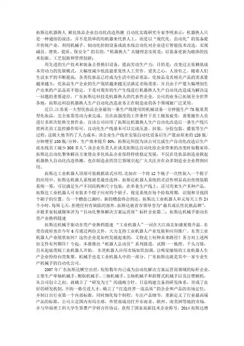
拓斯达机器换人掀化妆品企业自动化改造热潮自动化实践研究专家李明表示:机器换人只是一种通俗的说法,并不是简单的用机器来代替人工,而是以“现代化、自动化”的装备提升传统产业,利用机械手、制动化控制设备或流水线自动化对企业进行智能技术改造,实现减员、增效、提质、保安全”的目的。
“机器换人”关键理念实质是:以装备更新为载体的技术创新、工艺创新和管理创新;用先进的生产技术和装备去替换旧设备,提高劳动生产力;目的是:改变过去依赖低成本劳动力的发展模式,大幅度减少低技能重复性人工劳作。
爱美之心,人皆有之。
随着人们生活水平的不断提高,各类化妆品已经成为生活中的必需品,化妆品及其相关产品的需求量越来越大,化妆品生产企业的生产现状越来越无法满足市场需求,并且由于产量大幅增加生产出来的产品品质不稳定,于是对现有的生产生线进行机器换人生产自动化改造成为解决这一问题的重要途径,广东拓斯达科技是机器换人的代表性企业,公司的业务已拓展至全世界各地,拓斯达科技机器换人生产自动化改造业务正在制造业的各个领域被广泛采用。
近日,江苏某一大型化妆品企业最初一条生产线使用的机械设备一分钟能生产70瓶某类型化妆品,完全依靠劳动力来完成,且在高强度的工作条件下员工极易疲劳,需要操作人员进行多班次轮换交替作业,自该公司应用了拓斯达机器换人生产自动化改造后一条生产线只需两名员工监控操作即可,自动化生产线基本可以完成压盖、封装、分捡包装、灌装等生产过程,这极大地节约了人力成本。
该企业生产线在安装自动化设备后生产量由原来的120瓶/分钟增至180瓶/分钟,生产效率提升50%。
拓斯达科技为该公司完成生产自动化改造后生产流水线员工减少300多人”,该企业负责人在谈及拓斯达自动化给企业带来的改变时如数家珍。
拓斯达自动化整体解决方案使众多化妆品企业保持持续稳定发展,不仅在化妆品制造业掀起机器换人自动化改造热潮,也在制造业的其它领域引起广大关注并在众多制造业企业得到应用。

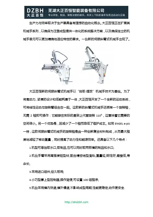
生产力与效率取决于生产要具备有理想的自动化概念。
大正百恒正在扩展其机械手系列,以确保为注塑成型提供一体化的系统解决方案,以及确保独立的机械手单元可以更加精确地适应特定的要求。
一台新的伺服斜臂式机械手出现了。
大正百恒新的伺服斜臂式机械手以“拾取-摆放”机械手技术为基础。
为了将高动力、紧凑的设计和低能耗集于一体,大正百恒开发了一个全新的运动系统,可将线性运动与旋转臂组合在一起。
这款新的斜臂式机械手还拥有一个旋转轴,无需Z轴即可操作:它能够在实际的基架上代替旋转110°,这意味着它需要的空间很小。
另一个优势是,因减少了一个轴而降低了维护成本。
如同ENGEL e-pic 一样,这款伺服斜臂式机械手的旋转轴是由一种创新复合材料制成,从而最大程度地减轻了移动重量,同时提高了动力性和能源效率。
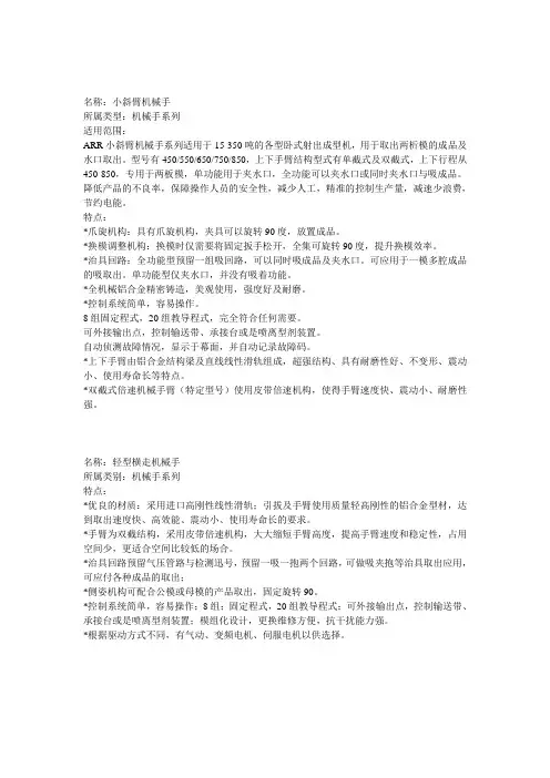
还具备以下几个特点:1.机型可单独取水口,取制品,也可以同时取两板模的制品和水口;2.机台手臂采用高强度铝型材,配合精密线型滑轨;重量轻,钢性好,磨擦低,寿命长;3.采用进口组件,经久耐用;4.小巧型掌上型控制器,操作简便,可设置100组程序;5.机台采用模内快速,模外慢速,不影响成型周期,性能更稳定,动作更安全.芜湖大正百恒智能装备有限公司是一家专业研发生产销售机械手的智能科技公司,其生产的各类机械手(双臂回斜式机械手、回斜式机械手、双截单臂回斜式机械手、立式注塑机专用机械手、单臂回斜式机械手、中型一轴伺服横走式机械手、中型两轴伺服横走式机械手、CNC悬挂式全伺服机械手、CNC开放式全伺服机械手、中型三轴牛头式伺服机械手、重型三轴牛头式机械手、重型三轴牛头式伺服机械手),类型丰富,控制精度高,性能优异,价格实惠,是您减省工人、提高效率、降低成本、提高产品品质、提升工厂形象的好选择。
芜湖大正百恒智能装备有限公司位于安徽省芜湖市,专业研发、制造、销售注塑机械手,车床、磨床、冲压上下料机械手及周边自动化设备。
产品广泛适用于基础工业,汽车零部件,电子通信,环保化粪池,检查井、垃圾桶、托盘、食品包装,PET瓶坯,家电设备,光学制造等。
可调节手臂训练器使用说明使用说明手臂训练器是一种专为锻炼手臂力量和增加肌肉稳定性而设计的训练设备。
它能够提供可调节的阻力,帮助用户定制个性化的训练计划。
本使用说明将为您详细介绍手臂训练器的功能和正确使用方法,以确保您能够从中获得最佳的训练效果。
一、组装手臂训练器在开始使用手臂训练器之前,您需要先组装好设备。
请按照以下步骤进行操作:1. 将手臂训练器的主体部分与支架连接起来,确保连接结实可靠。
2. 根据个人需要,调整支架高度并锁定。
一般来说,刚开始使用时,较低的高度可以更好地掌握平衡。
3. 将手臂训练器的阻力调节器安装在主体部分上。
您可以根据个人的力量水平选择适当的阻力。
二、正确的姿势1. 站立或坐下,并保持身体的平衡。
双脚平行分开与肩宽相似。
2. 握住手臂训练器的手柄,双手间距适当,保持舒适。
3. 伸直你的手臂,与肩膀平齐,手掌朝下。
确保手臂与肩膀之间的夹角大约为90度。
4. 稳定身体,并保持上身直立。
避免任何剧烈的动作或摇晃。
三、使用手臂训练器1. 慢慢地屈臂,将手臂训练器的手柄向胸部拉至最大限度,同时保持手臂与肩膀平齐。
此动作重点是用手臂的力量,而不是身体的其他部分。
2. 在最大拉伸位置停留一会儿,然后缓慢地将手臂恢复到开始的位置。
这个过程应该保持平滑且稳定,避免用力过猛或过快。
3. 根据个人的需要,重复上述动作,建议每组进行10-15次,然后休息片刻。
4. 根据您的训练计划,逐渐增加每组的重复次数和训练的组数。
5. 每次训练后,确保放松肌肉并进行适当的拉伸运动,以减少可能的肌肉酸痛和伤害。
四、注意事项1. 在开始使用手臂训练器之前,建议咨询专业教练或医生的建议,以确保您的身体状况适合进行手臂训练。
2. 在使用手臂训练器时,注意保持正确的姿势和动作。
不要使用过大的阻力,以免造成肌肉拉伤或其他伤害。
3. 如果感到任何不适或疼痛,应立即停止训练,并就医咨询。
4. 定期检查手臂训练器的各部件是否正常,如有发现损坏或松动的情况,请立即修复或更换。
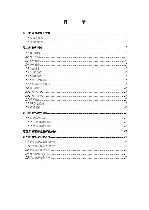
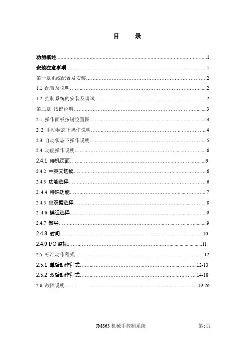
目录 (11)第一章系统配置及安装.................................................................................................................1.1配置及说明 (1)1.2系统的安装 (1) (33)第二章操作说明.............................................................................................................................2.1操作面板 (3)2.2停止状态 (4)2.3手动操作 (4)2.4自动操作 (5)2.5功能设定 (7)2.5.1一般功能 (7)2.5.2特殊功能 (7)2.5.3单、双臂选择 (9)2.5.4显示屏亮度调节 (9)2.6动作程序 (10)2.6.1程序选择 (10)2.6.2程序教导 (10)2.7时间修改 (11)2.8I/O信号监视 (12)2.9报警记录 (14)第三章动作程序说明................................................................................................................... (1515)3.1标准动作程序 (15)3.1.1单臂动作程序 (15)3.1.2双臂动作程序 (16)第四章报警信息及解决方法....................................................................................................... (1919) (2424)第五章接线及安装尺寸............................................................................................................... 5.1中继板输入输出接线图. (24)5.2注塑机与机械手连线图 (25)5.3中继板安装尺寸图 (26)5.4操作面板尺寸图 (27)5.5开关电源安装尺寸 (28)第一章系统配置及安装1.1配置及说明1.彩色显示部分:(一套)1)手控板2)按键板3)液晶2.主机部分:(一套)1)中继(I/O)板3.电源部分:(一套)1)开关电源4.其它1)37芯线一根2)蜂鸣器一个1.2系统的安装1、配线作业必须由专业电工进行。
HCX-5型智能数显测斜仪使用说明书冀制09000060号任丘市京联测斜仪厂通讯地址:任丘市乙-253信箱电话:E-mail:1、概述图1显示了测斜仪系统的各组成部分。
探头连着一根与读数仪相连的特殊电缆和带槽口的测斜管。
这本手册描述了测斜仪探头和电缆的使用及维护方法。
2、测斜仪原理在岩土工程领域,测斜仪主要用于测量大地运动,诸如:可能产生在不稳固边坡(滑坡)或挖方工程周围的侧向运动等。
也可用来监测堤坝、芯墙的稳定性,打桩或钻孔的布置的偏差,以及在回填、筑堤和地下储罐的土体沉陷等。
图2测斜管所有这些场合,通常要在土体的钻孔内安装一根管、或将管浇筑在混凝土结构中、也可将管埋在筑堤等之中。
该种测斜管有四个槽口(图2),以配合滑动式测斜仪探头的小滑轮(图1),探头悬在和读数仪相连的电缆一端,来测量测斜管的竖直倾斜,用这种方法来探测由于地层移动引起的倾斜。
探头本身包括一个受重力作用的铅垂摆,大多数测斜仪使用一个力平衡伺服加速度仪,其位置传感器可以探测铅垂的位置,并且提供足够的恢复力使摆回到竖直零位置。
从竖直零位置倾斜的越大,恢复力也越大,因而摆块不能自由运动。
恢复力的大小,转变成电信号输出,在读数装置上显示,成为倾斜的量度。
由于恢复力和倾斜角的正弦成正比,因而输出值也和测孔水平偏移成正比。
为了获得测斜仪测斜管周围地层的一个完整的观测报告,有必要在测斜管周围进行一系列倾斜观测。
测斜仪探头有两组小滑轮,距离相隔0.5m,将探头放到测斜管底部进行读数时,即开始了测斜管观测。
探头在每一个0.5米进行读数,一直到达测斜管的顶部,这组读数被称为A+读数,为使操作过程简单,一般在电缆0.5米作有一个标记。
把探头从测斜管中取出,旋转180°,重新放入测斜管中,方法同上,又可得到另一数据(A-读数)。
数据处理时,将读数(A+、A-)相结合(用一组数据减去另一组数据),以此来消除力平衡伺服加速度计的零偏的影响。
测斜仪探头在竖直位置时读数产生零偏差。
高宝印刷机械科技有限公司KC Printing Machine (Group) limited 19-1 Website: 斜臂式丝印机 使用说明书High precision oblique Arm screen printingmachineOPERATIONINSTRUCTION高宝印刷机械科技有限公司KC Printing Machine (Group) limited 19-2 Website: ●前 言欢迎您使用我司产品!我司热诚为您提供满意优质产品,并希望您对我公司提出宝贵意见,以便与您共求发展、共创双赢。
我司是集研发、制造、销售、产品服务为一体的企业,专注烫金机,移印机,丝网印刷及辅助设备的开发和制造。
我司技术力量雄厚、设备齐全、测试技术完善,拥有严谨的质量管理和完善的产品售后、技术咨询的服务体系。
我司产品的关键部件选用西门子、三菱、菲利浦、施耐德等日本、台湾、欧美国际知名品牌。
产品质量可靠,性能稳定。
我司的主要产品为:▲ 各类平面丝网印刷设备;烫金机,移印机; ▲ 网版制作、曝光及其辅助设备;▲ 紫外线(UV )干燥工艺如磨砂、晶体冰花、皱纹、七彩宝石等设备; ▲ 红外线(IR )干燥设备; ▲ 各类丝网印刷油墨和辅助器材。
产品广泛适用于精密电子、印制线路板(PCB )、电脑键盘、陶瓷电路、薄膜开关电路、场致发光片(EL )、液晶显示片(LCD )、手机视窗镜片、IML 、IMD 、信号显示(LED )、陶瓷玻璃、CD 光盘、铭板标牌、SMT 锡膏、PVC 、PET 、PC 胶片、广告、装璜、玩具、金属、皮革、塑料、无防布袋、服装印花、烟、酒、荼、药、包装印刷等行业。
公司以“精益求精、不断创新”的质量及经营理念, 孜孜不倦的追求精神,追求完美,跨越无限 ,与您携手共创美好未来。
ForewordWelcome to use our products!Our company dedicate to provide you with satisfactory quality, and we hope you can give me some valuable advices , so that we can seek mutual development, and create a win-win situation.Our company is high-technology enterprise focusing on pad printing machine, screen printing machines and hot stamping machine of developing, selling, manufacturing and service. Our company has strong technical experience, perfect processing machines, advanced testing technology and strict quality management control system.高宝印刷机械科技有限公司KC Printing Machine (Group) limited 19-3 Website: Components of our products are imported from Japan’s, Korea, America, and Euro such as Siemens , Mitsubishi, Philips, Schneider. Products is the first in the screen printing field in China with reliable quality and stable performance.Our products are widely used in many fields such as: precise electron , packing, advertisement, nameplate , keyboard, toys ceramic, plastic, plastics CD discs , PCB, LCD , LED, PVC, PET, advertising decoration, toys, metal, leather, plastics, non-anti-bag, garment printing, tobacco, wine package , tea, medicine, packaging printing and so on.Main Parameters高宝印刷机械科技有限公司KC Printing Machine (Group) limited 19-4 Website: ● 主要技术参数●机械的安装1、安装固定位置:将机械移至指定位置,调整机械的四个地脚至四个地脚轮离地。
一、交底目的为确保斜臂车在施工作业中的安全运行,降低事故风险,提高作业人员的安全意识,特进行斜臂车安全技术交底。
二、交底对象本交底适用于所有使用斜臂车进行吊装作业的施工人员、管理人员及操作人员。
三、交底内容1. 斜臂车基本知识(1)斜臂车是一种具有较大吊装能力的起重机械,主要用于建筑、桥梁、电力等领域的吊装作业。
(2)斜臂车主要由底盘、吊臂、卷扬机、行走机构等部分组成。
2. 操作规程(1)操作人员必须经过专业培训,取得相关操作证书。
(2)操作前应检查斜臂车各部件是否完好,液压系统、电气系统、制动系统等是否正常。
(3)吊装作业前,应确认吊装物品的重量、尺寸、形状等,确保吊装物品符合斜臂车的吊装能力。
(4)吊装过程中,严禁超载、超范围作业。
3. 安全注意事项(1)操作人员应穿戴符合安全要求的工作服、安全帽、安全鞋等防护用品。
(2)操作人员应熟悉斜臂车的操作规程和安全注意事项,严禁酒后、疲劳操作。
(3)吊装作业时,应确保吊装物品与吊钩连接牢固,严禁吊装物品松动或脱落。
(4)吊装过程中,严禁人员站在吊装物品下方,确保人员安全。
(5)吊装作业时,应设置安全警戒区域,严禁无关人员进入。
(6)吊装作业过程中,应密切观察斜臂车的运行状态,如发现异常情况,应立即停止作业,查明原因后进行处理。
4. 急救措施(1)如发生人员受伤,应立即停止作业,并拨打急救电话。
(2)对受伤人员进行现场急救,如止血、包扎等。
(3)将受伤人员迅速送往医院接受治疗。
四、交底时间本次安全技术交底时间为____年__月__日。
五、交底人交底人:____(姓名)六、接受人接受人:____(姓名)七、备注1. 本交底内容为斜臂车安全技术交底模板,具体操作时请根据实际情况进行调整。
2. 施工单位应定期对斜臂车进行维护保养,确保其安全性能。
3. 操作人员应严格遵守操作规程和安全注意事项,确保自身和他人的安全。
4. 施工单位应加强对斜臂车的安全管理,定期开展安全检查,及时发现并消除安全隐患。
斜臂单臂机械手安全操作及保养规程斜臂单臂机械手是一种使用在工业生产环境中的机械装置,能够执行自动化的生产流程,提高生产效率和质量。
然而,在操作和使用斜臂单臂机械手时,员工需要严格遵守一系列的安全操作和保养规程,以确保其正常操作和使用,同时保证员工的安全。
安全操作规程1. 遵守操作手册在操作斜臂单臂机械手之前,员工必须全面阅读机械手操作手册,并确保理解和掌握手册上说明的机械手的功能、性能和安全操作要求。
2. 穿戴个人防护装备在操作斜臂单臂机械手之前,员工必须穿戴好个人防护装备,包括安全帽、防护眼镜、安全手套等,确保自己的安全。
3. 遵守安全警示标志和提示信号斜臂单臂机械手上会配备一些安全警示标志和提示信号,员工必须遵循这些标志和信号,不能随意进入或接近机械手,以确保自身安全。
4. 保持机械手周围清洁员工在操作机械手时,必须保持机械手周围的工作环境清洁整洁,并且要避免机械手周围存在杂物或障碍物,以确保机械手的正常运行。
5. 防止机械手碰撞在操作机械手时,员工必须避免机械手发生碰撞或抵抗,这可能会损坏机械手,甚至对人员造成伤害。
6. 避免过度使用机械手过度使用机械手可能会导致机械手的磨损和故障,员工必须要严格遵守机械手的使用规程,避免过度使用。
7. 禁止行为在操作机械手时,员工必须严格禁止以下行为:•越过或触摸安全栅栏•离开工作位置不告知机械手的操作员•吸烟、吃东西或喝饮料等不安全行为•离开工作站时,不关闭机械手或关闭电源保养规程1. 定期检查和维护斜臂单臂机械手必须定期检查和维护,以确保其性能和安全。
例如,员工必须检查和更换润滑油、紧固螺丝、检查电气接线等。
2. 清洁机械手员工必须定期清洁机械手,包括外壳、工作台、操作面板等。
经常清洁可以有效保护机械手的性能和延长使用寿命。
3. 充分熟悉机械手的机构和部件员工必须熟悉机械手的机构和部件,并能够正确地安装和拆卸机械手。
4. 避免机械手的暴露机械手必须保持干燥和干净,并应避免暴露在阳光下或潮湿的环境中。
Double Arm AssemblyPole AssemblyBolt Through Base9mm (0.35”) holeSteel WasherM8x60mm Screw5mm Allen KeyHandgrip TabStep 2. Mount Pole Assembly (cont.)Step 3. Mount Double Arm Assembly2.4 Remove the M8 x 16mm Socket Head Countersunk Screws to release the Desk Clamp Bracket.2.3 The Desk Clamp bracket can be repositioned to suit different mounting surface thicknesses. The maximum mounting surface thicknesses supported are listed below from the Top to Middle and Bottom Screw Holes.Top 0 - 32mm (default)Middle 7 - 47mm Bottom 22 - 62mmTTMMBBM8 x 16mm Socket Head Countersunk Screw5mm Allen Key Desk Clamp Bracket Pressure PlateTable TopM8 x 16mm Socket Head Countersunk ScrewDesk Clamp Screw 5mm Allen Key 5mm Allen Key5mm Allen Key Double Arm AssemblyPole Top Cap2.5 Place in desired location.If you need to reposition the desk clamp bracket or you have no access to the rear of your table continue to Step 2.4.If you DO NOT need to reposition the desk clamp bracket and you have access to the rear of your table skip to Step 2.7.2.6 Reattach Desk Clamp Bracket.2.7 After positioning your Pole Assembly, screw Pressure Plate in and Tighten Firmly.3.1 Unlock Handgrip and raise so that Handgrip Tab protrudes. 3.2 Slip the Double Arm Assembly over the Handgrip Tab and then onto the Pole.3.3 Slide the Double Arm Assembly and Handgrip down the pole before locking the handgrip at the desired height.3.4 Insert Pole Top Cap into Pole. This is also where the Allen Key is stored.Desk Clamp BracketTop 29 - 69mm Middle 43 - 84mm Bottom 59 - 99mmx6.2 Cable Clips and Cable Stops can beinstalled to further manage cables.Please See Over.Step 4. Mount DisplaysStep 5. Adjust Height (Note: This procedure requires two people.)M4 Phillips HeadMounting ScrewsNote: Back to back configurations mayresult in clamp failure.Option 1: 75x75mm Hole Pattern Option 2: 100x100mm Hole PatternNote: Extend Arms toachieve 100x100mmhole pattern.Step 6. Cable ManagementCable StopCable ClipNote: Ensure enough cableslack is given to allow formovement.TightenLoosenTILT (screen angle up/down)TightenLoosenPORTRAIT/LANDSCAPEAllen Key Storage95ºMax.PAN (screen angle left/right)10º - 20º5º15ºInstallation CompleteNo portion of this document or any artwork contained herein should be reproduced in any way without the express written consent of Atdec Pty Ltd.Due to continuing product development, the manufacturer reserves the right to alter specifications without notice. Published 13.02.14 ©Step 6.2. Insert Cable StopsStep 8. Adjusting the Display BracketErgonomic GuidelinesMany experts believe that the extended use of any computer screen has the potential to cause serious injury to your eyes, neck and back. This can be largely avoided by correctly positioning your display.。
1、手臂的设计2.1、手臂伸缩的设计计算手臂是机械手的主要执行部件。
它的作用是支撑腕部和手部,并带动它们在空间运动。
臂部运动的目的,一般是把手部送达空间运动范围内的任意点上,从臂部的受力情况看,它在工作中即直接承受着腕部、手部和工件的动、静载荷,而且自身运动又较多,故受力较复杂。
根据液压缸运动时所需克服的摩擦、回油背压及惯性等几个方面的限力,来确定液压缸所需的驱动力。
手臂的伸缩速度为250mm/s行程L=300mm液压缸活塞的驱动力的计算P = P摩■ F密■ F回■ F惯式中P摩一一摩擦阻力。
手臂运动时,为运动件表面间的摩擦阻力。
若是导向装置,则为活塞和缸壁等处的摩擦阻力。
P密一一密封装置处的康擦阻力;P回一一液压缸回油腔低压油掖所造成的阻力;P惯一一起动或制动时,活塞杆所受平均惯性力。
p摩、P密、P回、%的计算如下。
2.1.1、P摩的计算不同的配置和不同的导向截面形状,其摩擦阻力不同,要根据具体情况进行估算。
图4-15为双导向杆导向,其导向杆截面形状为圆柱面,导向杆对称配置在伸缩缸的两侧,启动时,导向装置的摩擦阻力较大,计算如下:由于导向杆对称配置,两导向杆受力均衡,可按一个导向杆计算。
'M A "G总L = aF bG F b = Fa(L+a: l a」式中G总——参与运动的零部件所受的总重力(含工件重),估算G 总=G 工件+G手+G 手腕+G 手臂=(80+60+60+250)N=450NL ——手臂参与运动的零部件的总重量的重心到导向支承前端的距离(m),L=100mma --------- 导向支承的长度,a=150mm;丄一一当量摩擦系数,其值与导向支承的截面形状有关。
对子圆柱面:IJ=0.18代入已知数据得』二」=(1.27」1.57)取・i=1.5」J ――摩擦系数,对于静摩擦且无润滑时:钢对青铜:取」=0.1~0.15钢对铸铁:取」=0.18~0.3取」=0.15 ,—9总」=0.18H2 200 1 00=405NI a 丿1002.1.2、 P 密的计算同的密封圈其摩擦阻力不同,其计算公式如下:(1) “O'形密封圈当液服缸工作压力小于10Mpa.活寒杆直径为液压缸直径的一半,活塞与活塞杆处都采用“ O'形密封圈时,液压缸密封处的总的摩擦力为P 寸 1 '2 二 0.03F式中 F ——为驱动力,P ——工作压力(Pa); P <10MPa, J =0. 05~0.023,取 p=2Mpa, J =0.06; d L 伸缩油管的直径,d=7mm; 密圭寸的有效长度(mm).得 P g =0.05 P2.1.3、 F 回的计算般背压阻力较小,可按F 回=0.05PF fe =G 总v总、gt450 0.29.81.0.2= 45N G 总一一参与运动的零部件所受的总重力(包括工作重量)(Ng 一一重力加速度,取 9.81 m/s 2v 一一由静止加速到常速的变化量|_v =0.2m/s t 一一起动过程时间(s ), —般取0.01~0.5s ,对轻载 低速运动部件取较小值,对重载高速运动部件 取较大值。
七自由度柔性机械臂机构说明设计目标由于人工成本的不断提升,人们的刚性需求也不断的扩大,生产自动化越来越被人们所重视。
也是社会发展的必然。
让机器人去完成一些高危、肮脏、重复、精度高的工作。
由此,设计一款高精度,高灵活性的机器臂显得更为重要。
设计的目标:高精度仿人工业机器人。
运用先进的仿生理论与柔性设计为基础,设计开发用二次式运动反馈来实现其高精度控制,合理的仿人机构来完成动动。
机械臂整体设计方案一、功能需求:满足实现模仿人类手臂的基本功能,自由度包括手臂的肩部的抬起,摆动,旋转,肘部的弯曲,腕部的旋转,弯曲,摆动共7个自由度。
(图一)图一图二二、优化后确定的构型:自由度包括手臂的肩部的摆动,抬起,大臂旋转,肘部的弯曲,小臂的旋转,腕部的弯曲,摆动共7个自由度。
(图二)三、驱动模块示意设计:(图三)胡克定律是力学基本定律之一。
适用于一切固体材料的弹性定律,它指出:在弹性限度内,物体的形变跟引起形变的外力成正比。
这样增加了力的反馈测量。
在弹性材料在弹性限度内形变时,测得其形变量,从而计算出受力与关节下方所处的位置。
1.先进行测试图三四、机械臂的具体设计方案,(图四)五、各关节的受力分析:基本尺寸图(图五)图五L1=426mm,L2=293mm,L3=108mm,L4=442mm。
六、马达的初选谐波减速器的优点:Harmonic减速器结构简单,体积小,重量轻、啮合的齿数多、承载能力大、运动精度高、运动平稳、间隙可以调整、传动效率高、同轴性好、可实现向密闭空间传递运动及动力。
瑞士Maxon电机优点:轴向窜动和径向跳动小、温度范围大、回差小等,并且电机型号全编码器与抱闸与控制器配套全面。
瑞士Maxon电机与日本Harmonic谐波减速器选型需求示例图片:图六马达1:EC90flat 90W扭力:4.67 nm 0.387nm;转速:3190rpm;重量:648g减速器1:CSG-25-160 减速比:1:160;最大扭力:314nm;正常:176nm;重量:420g马达2:EC-4pole max30 200W 扭力:3.18 nm 0.112nm;转速:17000rpm;重量:300g减速器2:CSG-25-160 减速比:1:160;最大扭力:314nm;正常:176nm;重量:420g马达3:EC max40 170W 扭力:;转速:9840rpm;重量:580g减速器3:CSG-17-120 减速比:1:120;扭力最大:112nm;正常:70nm;重量:150g马达4:EC45flat 70W 扭力:;转速:4840rpm;重量:110g减速器4:CSG-20-160 减速比:1:160;最大扭力:191nm;正常:120nm;重量:280g马达5:EC-4pole max30 100W 扭力:1.24nm 0.0 63nm;转速:17800rpm;重量:210g减速器5:CSD SHD-17-100 减速比:1:100;最大扭力:71nm;正常:37nm;重量:100g 马达6:EC45flat 70W 扭力:0.13 nm 0.17nm;转速:4840rpm重量:110g减速器6:CSF-11-100 减速比:1:100;最大扭力:25nm;正常:11nm;重量:50g马达7:EC-4pole max30 100W 扭力:1.24nm 0.0 63nm;转速:17800rpm;重量:210g减速器7:CSF-11-100 最大扭力:25nm;正常:11nm;重量:50g说明:EC45flat 70W要更换为EC-I40 70W+MR七、受力分析:有效扭力计算公式:(堵转-连续)*0.3+连续质量分配:设大臂小臂均为,外径D=110mm,假设主体为外壁壁厚为L=5mm的铝壳,长度为H=250mm,则体积为:412cm3,铝的密度2.7g/cm3,外壳质量为1.1kg大臂部分质量有马达3(580g)减速器(150g),外壳(1.1kg);小臂部分有马达4567(110g,210g,110g,210g),减速器4567(280g,100g,50g,50g),外壳(1.1kg);手部主要是灵巧手的质量设为1kg;外加假设载荷6kg。