FMX-12设备IONOS中文手册(V1[1]1)
- 格式:docx
- 大小:1.32 MB
- 文档页数:28

ZX3-90PI12-inch Two-Way Passive90° x 50°, 600W Weather-Resistant Loudspeaker SystemGeneral Description:Technical Specifications:Key Features:DVX3121 12” LF Transducer with Forced Air • CoolingND2 2” Voice Coil, 1” Exit Neodymium • Compression Driver90° x 50° Coverage Pattern• 600W Continuous (2400W Peak) Power • HandlingHigh Sensitivity, 131 dB Maximum SPL • Adjustable Monitor Angle (45° or 55°)• 2 Anchor Plates for Single Stud Fittings and • 7 Integral Suspension Points Available in Black or White• All Weather IEC 529, IP44, & MIL810 • Environmental Specs Full Line of Accessories•The Electro-Voice® Zx3 is the new standard of no compromise audioperformance and versatility in a simple to use, compact package. The ZX3-90PI features a molded polymer enclosure that is inherently water resistant. The addition of a multilayer grille with hydrophobic cloth and a gland nut input connection allows for a highly weather resistant system.At its heart are the transducers. First is the DVX3121 high performance low frequency transducer. EV used advanced computer aided design tech-niques to create forced air, directional voice coil cooling for high power and efficiency. Finite element analysis was used to optimize the suspension and magnetic structure for long, linear travel to provide low distortion and greater LF extension. These features and details, such as forged magnetic components and special materials, provide reliability with a 500W power rating in a lightweight transducer. Next is the ND2, a 2-inch voice coil com-pression driver based on neodymium motor structure to allow for maximum output while reducing size and weight to a minimum. Its precision phasing plug and titanium diaphragm provide better HF performance, while the integral heatsink provides cooling for high power output.The high tech enclosure uses injection-molded high-impact polypropylene structural foam to make the Zx3 incredibly durable. The enclosure geometry elements have been carefully designed to provide maximum rigidity and bass response. By design the Zx3 is also a perfect solution for stage moni-tors by allowing two angles (45° or 55°) without any additional accessories.Two coverage patterns are available; 60° x 60° coverage for long-throw and cluster applications, 90° x 50° coverage for wider coverage or shorter distances.The Zx3 is equipped with two anchor plates for rigging with single stud-fittings, along with two more possible anchor plate attachment points on the bottom. For permanent suspension or attaching brackets, the Zx3 also has two M8 inserts on the top and bottom, two under the handle, and one on the back of the enclosure, for a total of 7. All versions are available in black or white.Freq. Response 1 (-3 dB):58 Hz - 15 kHz Freq. Range 1 (-10 dB):48 Hz - 20 kHz Rec. Hipass Frequency:50 HzAxial Sensitivity 1:97 dB (1W/1m)Max. Calculated SPL:131 dB Coverage (Horiz. x Vert.):90° x 50°Power Handling (Passive):600W Continuous, 2400W Peak LF Power Handling (Biamp):500W Continuous, 2000W Peak HF Power Handling (Biamp):40W Continuous, 160W PeakLF Transducer:DVX3121, 12 in (305mm) Driver HF Transducer:ND2, 1 in (25.4mm) exit NeodymiumCompression DriverCrossover Frequency: 2 kHz Nominal Impedance:8 Ohms Minimum Impedance: 6.2 OhmsConnectors: 2 Conductor SJO Cable and Gland NutEnclosure Material:Polypropylene Structural FoamSuspension:Enclosure has locations for 4 Single-StudAttachment Plates and 7 Forged Steel Eye-bolts - 2 on Top, 2 on Bottom, 2 on Side, and 1 on Rear of EnclosureGrille:Polyester Powder Coated, 16GAGalvanized Steel, with Rotatable LogoEnvironmental Spec:IEC 529 IP24 / IP44Dimensions (H x W x D):613mm x 397mm x 362mm(24.14” x 15.64” x 14.26”)Net Weight:19.8 kg (43.7 lbs)Shipping Weight:22.1 kg (48.6 lbs)1Half Space Measurement.Frequency (Hz)Polar Plots (1/3 Octave):Engineering Data SheetHorizontal = Black Vertical = Grey12000 Portland Avenue South, Burnsville, MN 55337Phone: 952/884-4051, Fax: 952/884-0043© Bosch Communications Systems 07/2008Part Number LIT000172 Rev AU.S.A. and Canada only. For customer orders, contact Customer Service at:800/392-3497 Fax: 800/955-6831Europe, Africa, and Middle East only. For customer orders, contact Customer Service at:+ 49 9421-706 0 Fax: + 49 9421-706 265Other Internatonal locations. For customer orders, Contact Customer Service at:+ 1 952 884-4051 Fax: + 1 952 887-9212For warranty repair or service information, contact the Service Repair department at:800/685-2606For technical assistance, contact Technical Support at: 866/78AUDIOSpecifications subject to change without notice.Electro-Voice ®Dimension Drawings:Bottom ViewPerformance Match301576-001 SbA760, 120V Single 15” Powered Sub, 760W • D170312 CP3000S, 120V Power Amplifier, 2 x 1100W • D170401 CP4000S, 120V Power Amplifier, 2 x 1400W • D170317CPS2.11, 120V Power Amplifier, 2 x 1100W•Accessories301625-001 CB5-B, Array Bracket Kit (Black)• 301625-002 CB5-W, Array Bracket Kit (White)• 301634-000 EBK-3, Forged M8 Eyebolt Kit, Set of Three • 301633-000 SSK-1, Single-Stud Rigging Kit, Set of Three • ASY000032-001 MB3-B, Wall/Ceiling Mount Bracket (Black)• ASY000032-002 MB3-W, Wall/Ceiling Mount Bracket (White)• ASY000031-001 HDC-3, Heavy-Duty Stackable Cover (Black)• KIT000023-001 TMK-ZX3, Truss-Mount Kit, Includes VSA-1, •TCA-1, and HA-3 (Black)Zx3 Part NumbersPRD000117-001 Zx3-90B, 90° x 50° Horn, Black Finish • PRD000117-002 Zx3-90W, 90° x 50° Horn, White Finish • PRD000117-003 Zx3-60B, 60° x 60° Horn, Black Finish • PRD000117-004 Zx3-60W, 60° x 60° Horn, White Finish • PRD000117-005 Zx3-90PI-B, 90° x 50° Horn, Black Finish, •Weather ResistantPRD000117-006 Zx3-90PI-W, 90° x 50° Horn, White Finish, •Weather ResistantPRD000117-007 Zx3-60PI-B, 60° x 60° Horn, Black Finish, •Weather ResistantPRD000117-008 Zx3-60PI-W, 60° x 60° Horn, White Finish, •Weather Resistant。

FMX系列数字交叉连接复用设备广州泓讯通讯设备有限公司GUANGZHOU HONGXUN COMMUNICATION EQUIPMENT CO.LTD目录一、系统简介 (2)1.1、系统概述 (2)1.2、监视与控制 (3)1.3、操作安全 (3)二、典型应用 (3)三、设备配置 (7)3.1、设备组成 (7)3.2、业务接口板 (8)四、系统功能 (15)4.1、概述 (15)4.2、链路接口 (15)4.3、数据与信令交叉连接 (15)4.4、同步 (16)4.5、监控与管理 (17)4.6、电源 (17)五、机械结构 (17)5.1、前接入子架(FMX12) (18)5.2、后接入子架(FMX4) (19)六、网管系统 (20)6.1、CT维护终端网管系统 (20)6.1.1 CT与FMX系列设备的连接 (20)6.1.2 软件环境 (22)6.1.3 CT网管系统结构体系 (23)6.1.4 本地维护终端 (23)6.2、IONOS NMS网络管理系统 (24)6.2.1 IONOS NMS网管拓扑 (25)6.2.2 IONOS NMS整体结构体系 (25)6.2.3 IONOS NMS软件结构 (26)6.2.4 硬件结构 (26)七、技术指标 (27)一、系统简介1.1、系统概述由于现代传输网络全面向数字传输网络转换和愈来愈广泛的先进新通讯业务一体化的需要,数字交叉连接系统已成为现代传输网络中至关重要的组成部分。
它们必须能够复用、交叉连接、插入分出和提供广泛的业务,包括(参见图1.1):●电话或音频信道;●高、低速率数据信道;●10/100M以太网IP信道;●2048Kb/s脉冲编码调制电路;●ISDN基本速率接入信道和基群速率接入信道;●接入数据传输单元,支持与低、中和高速率租用线路的远端连接…。
在各种各样的应用中提供接入公用和专用通信网络的多种类型终端,支持广泛的用户业务接口。

12导联心电导联心电信号测量信号测量信号测量系统系统编写人 CAC版本号 Rev.0------------------------------------------------------------------------------------------------------------ 本报告为Analog Devices Inc. (ADI) 亚洲技术支持中心专用,ADI 可以随时修改本 报告而不用通知任何使用本报告的人员。
如有任何问题请与 china.support@ 联系。
------------------------------------------------------------------------------------------------------------Revise History DateRevision Author 2012-10-09Rev.0 CAC此参考设计仅供参考使用此参考设计仅供参考使用,,用于协助ADI 客户进行设计与研发客户进行设计与研发。
ADI 有权在不事先通知的情况下, 随时对所提供的参考设计进行更改随时对所提供的参考设计进行更改。
客户应对其参考或使用该参考设计自行负责客户应对其参考或使用该参考设计自行负责。
请在参考或使用此参考设计前仔细阅读ADI 提供的所有相关资料提供的所有相关资料。
ADI 不对任何参考或使用该参考设计所产生的风险的承担责任用该参考设计所产生的风险的承担责任。
目录1简介 (1)2硬件设计 (1)2.1直流耦合心电信号测量系统 (2)2.2系统设计 (2)2.3硬件电路 (3)2.4心电信号发生器 (4)3DSP固件设计 (5)3.11mv定标 (5)3.2过采样 (5)3.3数字滤波器设计 (5)3.48通道至12导联信号转换 (6)3.5导联脱落检测 (7)3.6起搏信号检测 (7)4心电信号测量系统的软件设计 (7)5心电信号测量系统快速使用手册 (8)5.1软件安装 (8)5.2硬件连接 (11)5.3软件启动及操作 (11)1 简介心电图(ECG)信号测量系统通过测量活组织表面电位来记录心脏在一段时间内的电性活动。

FMX12 培训手册深圳市特发信息泰科通信分公司(第一节FMX12设备介绍)一、概述认识FMX设备的不同组成部分概述▪数字交叉复用设备•64kbit/s•Nx64kbit/s▪容量•26x2M 数据流(内部交叉连接)▪功能二、典型应用▪各种数据类型例如:•电话和音频通道•低/中/高速数据通道• 2.048M PMC 通道•ISDN接入(PRI 或BRI)▪具有优化的2.048Mbit/s 通道数据和信令处理▪接口▪环回-告警接口(P3-46、P3-49)▪时钟、测试、维护接口▪F接口(P3-52)▪P2接口▪P1和网管接口(P3-58)FMX有两种类型的模块:▪公共单元▪接口卡接口卡•1-4X2MBIT/S (A2S CARD)•3X64KBIT/S (3 64 I CARD)•3XV.24/V.11•4XV.24/V.28•6通道四线E&M (6PAFC CARD) •6通道用户接口卡(SUBSCR)•12通道交换侧接口卡(EXCH12FMX12设备功能复用模式FMX从用户侧接收带信令和业务的支路数据流,复接成2.048Mbit/s的信号交叉模式FMX作为交叉网络,任意两个端口可交叉连接GIE-P 卡主要功能•处理LCT(或RMS)与FMX的网管通讯•数据库•COB卡保护切换的控制GIE卡一定插在机架的15槽GIE-P 卡接口•监控和维护的管理接口•网管接口(RMS 和LCT)•注册和存储系统参数•告警和状态数据的管理•产生和存储事件记录两个外接的接口:P1/P2 同步V.11的接口供LCT 或RMS 的连接交叉连接接口卡主要功能:•交叉连接•同步•定时电路COB 卡插在16和17槽位外部接口:• 2.048Mbit/s同步时钟的输入和输出内部接口:•每个接口卡的时钟传送•每个接口卡的连接TS 的连接CAS 的连接NX4 kbit/s 的EOC帧中继的EOCCOB 卡前面板A2S接口卡•4个HDB3接口•兼容ITU-T G.703和G.704•支持单速率和nx64kbit/s 速率的连接•传输质量的检查结构化4X2M接口提供以下功能:•虚拟接口,不同的NX64K比特流可以复接到同一个2M通道。
124514CONTENTSFEATURES ACOUSTIC CHARTS INSTALLATION DIMENSIONS SPECIFICATION LIMITED WARRANTY45Hz-18kHz95dB1.8kHz 300W 8Ω<3%NL4×2,1+ 1- 27.5kg 30.0kg402×440×650mm 550×510×770mmSPECIFICATIONTransducerSensitivity(1W/1m)Frequency response(-3dB)THDNet Weight Gross Weight Dimension(W ×D ×H)Packing Dimension(W ×D ×H)Crossover Point Rated Power (RMS )Rated Impedance Input Connectors Dispersion (H ×V )◇ 12" high efficient professional speaker with unique LF extension technology, the LF can be lower to 35Hz(SPL-10dB).◇ Computer optimized simulation design make sure the good frequency response and excellent phase feature.◇ Two transducers two way full range speaker with Hi-Fi level performance ◇ One 12 professional woofer."◇ One compression driver with 3" magnalium diaphragm. ◇ 60°X60° wide dispersion horn.◇ Independent crossover circuit for woofer and tweeter, low distortion and interferer.◇ Single Amplifier driving mode.◇ Suitable for the application in rock bar, night club, living performance and portable sound system.FEATUREB3 X series speaker is mainly designed for all kinds of rock bar, entertainment bar, club, all kinds of living performance, and portable sound reinforcement applications.12 inch full range and 15 inch full range speakers are trapeziform design; it will be very convenient tomake an array. Selected highintensity plywood has enough strength and can absorb the noise of resonance. Standard mounting&flying system and SPK socket are very easy for the installation and connection. X Series products are developed and produced by combination of the latest computer stimulation design technology, the latest loudspeaker material and manufacturing technology. All transducers adopt the optimized magnetic circuit having high magnetic energy, low distortion and excellent ventilation/cooling system. LF uses nonlinear thickness long fabric paper cone with waterproof feature and special damping Glue treated, and high power sandwich type voice coil. HF adopts high temperature treated magnalium diaphragm, voice coil with copper cladding aluminum wire and compression cavity designed with linear phase technology. Wide dispersion horn makes sure the excellent sound coverage. The patented HF protection circuit grantee the high reliability and low distortion.INTRODUCTIONHF: 3" x 1, LF: 12" x 1119/125dB(Peak)Max. SPL 60° x 60°2 501 002 005 001k2k5k1 0k2 0k20Hz1 1 0d B 1 8 0°D eg1 0 0 1 0 8°9 0 3 6°8 0 - 3 6°7 0 - 1 08°6 0- 1 80°C L20 Hz501002005001K 2K 5K 10K 20KOhm678910203040506070Impedance vs FreqFREQUENCY/RESPONSEPHASE IMPEDANCE RESPONSE-LFFREQUENCY RESPONSEPHASE RESPONSE650m m402mm440mm300m m321mmBack viewSide view Front viewTop viewDIMENSIONSINSTALLATIONLIMITED WARRANTYIf malfunction occurs during the specified warranty period from the date of original purchase,the product will be repaired or replaced without charge by Elder Audio.The Limited Warranty does not apply to:(a)exterior finish or appearance;(b)certain specific items described in the individual product data sheet or owner's manual;(c)malfunction resulting from use or operation of the product other than as specified in theindividual product data sheet or owner's manual;(d)malfunction resulting from misuse or abuse of the product;(e)malfunction occurring at any time after repairs have been made to the product by anyoneother than Elder Audio Service or any of its authorized service representatives.To obtain warranty service, customer must deliver proof of purchase of the product in the form of a bill of sale or receipt invoice.X12i Speakers and Speaker Systems are guaranteed against malfunction due to defects inmaterials or workmanship for a period of three (3) years from the date of original purchase. The Limited Warranty does not apply to burned voice coils or malfunctions such as cone and/or coil damage resulting from improperly designed enclosures. Additional details are included in theLimited Warranty statement.X12i Accessories are guaranteed against malfunction due to defects in materials or workmanship for a period of one (1) year from the date of original purchase. Additional details are included in the Limited Warranty statement. .X12i Flying Hardware (including enclosure-mounted hardware and rigging accessories) isguaranteed against malfunction due to defects in materials or workmanship for a period of one(1) year from the date of original purchase. Additional details are included in the Limited Warrantystatement.Specifications are subject to change without notice.。
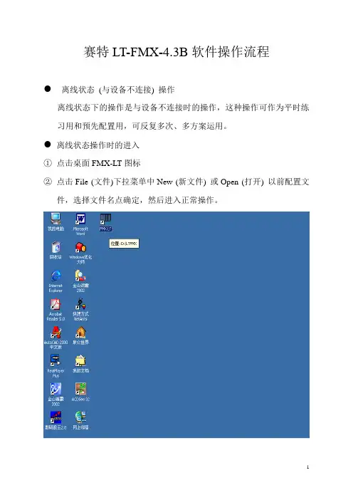
赛特LT-FMX-4.3B软件操作流程●离线状态(与设备不连接) 操作离线状态下的操作是与设备不连接时的操作,这种操作可作为平时练习用和预先配置用,可反复多次、多方案运用。
●离线状态操作时的进入①点击桌面FMX-LT图标②点击File (文件)下拉菜单中New (新文件) 或Open (打开) 以前配置文件,选择文件名点确定,然后进入正常操作。
离线状态操作时的退出①当配置完成后需退出时,点击File (文件)下拉菜单中Close (关闭),出现对话框问在你退出之前存不存配置结果,可选择Yes 或No。
如选Yes 输入要存配置的文件名如:长沙变.tpi。
②再次点击File (文件)下拉菜单中Quit (退出) 退出操作。
●在线状态(与设备连接) 操作在线状态下的操作是与设备连接时的实时操作,如果设备工作在运行状况下,操作时请谨慎。
●在线状态操作进入退出①点击桌面FMX-LT图标②点击Management network (网络管理)下拉菜单中Open network port (打开网络口)。
③在画面显示与设备连接成功后,再次点击Management network (网络管理)下拉菜单中Log on (登录),然后进入正常操作。
④操作完后须退出操作系统时,点击Management network (网络管理)下拉菜单中Log off (中止)。
在下面图中选择Yes。
⑤再次点击Management network (网络管理)下拉菜单中Close networkport (关闭网络口)。
⑥再次点击File (文件)下拉菜单中Quit (退出)退出操作。
● Configuration (配置)下的操作①Manage hardware description (硬件描述管理),完成功能:完成FMX12子框从3~14插槽,具体插槽接口板的配置,A2S (4×2Mb/s接口板)2M 口的设置;FXS/FXO接口电平调整,FXS用户延伸/用户热线设置;4W E/M 2W/4W 工作方式设置、接口电平调整和EM状态设置;V.24/V.28、V.24/V.11工作方式、传输速率、控制状态和数据格式设置等。

Mentor12 EN v3_SMC fichas 09/08/13 15:09 Página 1Advanced Test Equipment Rentals 800-404-ATEC (2832)®E s t a b l i s h e d1981Swivel Touch-Sensitive 800x600 TFT. Built-in WindowsCE® computer .Rotary encoder for adjustmentof test values and sliders.Ergonomic custom case withanti-slip coating and transporthandles. 2it into the Mentor 12 and it will reproduce the signal ontothe relay in a matter of seconds.The VGA connector can be used tohook up external monitors orprojectors for a larger viewingsurface or for training purposes.UNIQUE FEATURES STAND-ALONE FUNCTIONALITY, WITHOUT PC EASY AND INTUITIVE TOUCH SCREEN Small foot print, easy access to all connections and adjustable screenLow Level Outputs, USB and Ethernet connections4You might not need twelve channels right now. Start with aRegardless the number of amplifiers in your Mentor 12, you can also combine them in series and in parallel to attain greater voltage and current levels. The output configuration screen displays a menu with all the possible combinations and a visual guide to help you at connecting the relay. There is no need to calculate partial current, voltage or phase angle values as the Mentor 12 manages and shows each group of combined channels as if it were a single “virtual “one.Furthermore, each voltage amplifier can be switched to current mode by a simple touch on the configuration screen. This feature allows, for example, to convert a Mentor 12 3v3i (3 voltage + 3 current channels) to a six-current test set when the need for testing three-phase differential relay arises.Low Level Outputs and superimposed harmonics for every source can also be activated in this control. You can accurately measure the output from a transducer, an energy meter or any other measurement device by connecting it to the analogue or binary inputs while injecting known quantities with the Mentor 12.PRODUCTIVITYThe Mentor 12’s human interface is organized to complete the job safely and accurately in the shortest possible time. Locating the necessary controls and the relevant test information will take just a few seconds to the untrained expert. The Basic Control panel has been designed especially for him. Adjusting a few values and testing a handful of trip points in the relay is a snap, thanks to the touch-sensitive panel and the rotary knob. There is no need to even look at the relay, as its response is displayed on the control screen in real time.The Mentor 12 includes the transient fault Playback as standard. You only need to copy your COMTRADE files into a USB pendrive, plug it into the unit and press Playback. If you want, you can assign each current and voltage signal in the recording to specific current and voltage channels for the playback. You can map the recorded binary information and the response of the relay to any of the binary outputs and inputs in the Mentor 12. You can also discard the unneeded signal’s sections or adjust the best transformation ratio for the playback. Press Playback to examine the streamed signals and the relay’s reactions in the screen.Combining two voltage channels in series COMTRADE transient playback②③④⑤⑥⑦⑧⑨⑩⑪⑫⑬⑭Fault FunctionFault Execution Ramp SetupDual Ramps executionPulse Ramp function 67Binary Search State Sequencer function COMTRADE transient playback Results Manager Measurement settings´s behaviorTimer SettingsBinary input selection and trip mode Binary inputs configuration Internet upgradingStates sequence with GPS8910Test procedures defined within ROOTS can be directly executed on a connected SMC test set. For a MENTOR 12 equipped with the Smart Test Tools module, the test procedures can also be transferred fromread and executed by the MENTOR 12 withoutDevice Panel Test List Screen Test Screen Test ReportClick Sequence TestElement list and characteristic templates Test SettingsAngle View- Pick up/drop out - Cold Load- I2/I1 Ratio- Fuse Failure- Reset TimeClick Sequence Test Distance Zones Characteristic EditorSearch TestDifferential shot testDifferential relay characteristic editor Technical dataHarmonic Restraint Test。

MICRO Hi-Fi SYSTEM ] USER GUIDE 3want to play.station sound effect.SLEEP Turn on or offMP3 Info while a file isimpressions. To change the functions, you can scroll throughthem and select one. (see Listening to the CDs)once to repeat the track REPEAT twice to CD. The MICRO Hi-Fi SYSTEM ] USER GUIDE 5MICRO Hi-Fi SYSTEM ] USER GUIDE 7Listen to cassette tapes - more you can doTo Play Fast backward or ForwardAfter pressing bb /BB during playback, or stop, press B at a point you want.Listening to the radio - more you can doLook for radio stations automaticallyPress - TUNING +(o r TUN.- /TUN.+) for more than 0.5 second. The tuner will scan automatically and stop when it finds a radio station.Delete all the saved stationsPress and hold PROGRAM MEMORY or PROGRAM/MEMO for two sec-onds. “CLEAR” shows. Press STOP CLEAR (or x )to erase all the saved stations.Choose a ‘preset number’for a radio stationSelect a station you want by pressing - TUNING +or TUN.- /TUN.+.Press PROGRAM MEMORY or PROGRAM/MEMO ,the station flashes.Press - PRESET +or PRESET/FOLDER to select the preset number you want. Press PROGRAM MEMORY or PROGRAM/MEMO to save it.Improve poor FM receptionPress MODE/RIF on the front panel . This will change the tuner from stereo to mono and usually improve the reception.See information about your radio stations - OPTIONALThe FM tuner is supplied with the Radio Data System (RDS) facility. This shows the letters RDS on the display, plus information about the radio sta-tion being listened to. Press RDS on the front panel several times to view the information.PTY - Programme Type, such as News, Sport, Jazz Music.RT - Radio Text, the name of the radio station.CT - Time Control, the time at the location of the radio station.PS - Programme Service name, the name of channel.You can search the radio stations by programme type by pressing- PRESET +. The display will show the last PTY in use. Press - PRESET +one or more times to select your preferred programme type. Press and hold - TUNING +. The tuner will search automatically. When a station is found the search will stop.MICRO Hi-Fi SYSTEM ] USER GUIDE 9Use your player as an alarm clockPress and hold TIMER for two seconds. Each function, TUNER, CD, USB (in the USB supplied models)flashes for two seconds. Press SET when the function you want to be woken by is showing.If you choose TUNER you will be shown the stations you have saved as presets. Use - TUNING + to select the station you want, then press SET . You will be shown the ON TIME display. This is where you set the time you want the alarm to go off. Use - TUNING +to change the hours and minutes and SET to save.You will then be shown the OFF TIME display. This is where you set the time you want the function to stop. Use - TUNING +to change the hours and minutes and press SET to save.Next you will be shown the volume (VOL) you want to be woken by. Use - TUNING +to change the volume and SET to save. Switch the system off. The clock icon shows that the alarm is set.When the system is turned off you can check the time the alarm is set for by pressing TIMER . You can also turn the alarm on and off by pressing TIMER . To set the alarm to go off at a different time, switch the system on and reprogramme following the same steps as initially.About MP3/WMAMP3/WMA Disc compatibility with this unit is limited as follows:• Sampling Frequency : 8 - 48 kHz (MP3), 32 - 48 kHz (WMA)•Bit rate : 8 - 320 kbps (MP3), 48 - 320 kbps (WMA)• CD-R physical format should be “ISO 9660”• If you record MP3/WMA files using the software which cannot create a FILE SYSTEM, for example “Direct-CD” etc., it is impossible to playback MP3 files. We recommend that you use “Easy-CD Creator”, which creates an ISO 9660 file system.•File names should be named using 30 letters or less and mustincorporate “.mp3”,“.wma” extension e.g. “********.MP3” or “********.WMA”•Do not use special letters such as “/ : * ? “ < >”etc.•Even if the total number of files on the disc has more than 1000, it will only be shown up to 999.MICRO Hi-Fi SYSTEM ] USER GUIDE 11Designs and specifications are subject to change without notice.。
FMX12 硬件简易安装手册一、FMX12设备面板图(根据项目制定)二、FMX12设备硬件安装规则1.FMX12设备A端接线规则2.FMX12设备B端接线规则3.FMX12设备板卡安装规则一、FMX12设备面板图(根据项目制定)二、FMX12设备硬件安装规则1.FMX12设备A端接线规则举例说明出线区图注:1.设备出线是根据左边出电源线,右边出音频数据线(为布线美观合理便于维护操作,放线缆时首先要做好每根线缆A端和B端做标识,以免接好A端,忘了对应B 端那根);2.电源线A端固定接电源接口,B端特别注意区分正负极接-48V直流电源;3.2M线A端注意如1x2M、1x2M 、2x2M对应上中下的接口,B端接DDF架;4.EM线、V24/V28线、S线、O线等线缆A端插入顺序从上至下为:TOP MIDDLE BOTTOM.此标记线缆上已注明,B端接VDF架;5.按举例插板来说明:A.14、13槽位是A2S(2M板),则相对应的Slot14、Slot13对应的3个接口应插“2M线”。
2M线插入方式有些特殊,对应BOTTNOM位置插入的是2x2M线缆,即出1#、4#两个2M。
MIDDLE、TOP对应位置插入的是1x2M线缆,分别对应是2#2M 和3#2M。
线缆上标记字母“EM”的为对应2M的发,“REC”的为对应2M的收。
B.12、11槽位是6PAFC(EM板),则相对应的Slot12、Slot11对应的3个接口应插“EM线”。
线缆插入顺序从上至下为:TOP MIDDLE BOTTOM.此标记线缆上已注明。
C.10、9槽位是V24/V28(V24/V28板),则相对应的Slot10、Slot9对应的3个接口应插“V24/V28线”。
线缆插入顺序从上至下为:TOP MIDDLE BOTTOM.此标记线缆上已注明。
D.8、7槽位是SUBSCR(S板),则相对应的Slot8、Slot7对应的3个接口应插“S线”。
Cautions for proper and safe operation. To use this product safely, please read this instruction manual carefully. Incorrect operation may cause malfunction, damage or accident. The cautions and warnings in the document are indicated by the following:m WARNING: I ndicates that incorrect use may result inservice injury or loss of life.m CAUTION: I ndicates that incorrect use may result inservice injury or property damage.m WARNING:1. Do not apply pressure greater than the maximumallowable pressure. This may cause damage or rupture the pressure element, resulting in injury or damage to the surroundings. 2. Do not use this product to measure fluid which causes gas/liquid contact area to corrode. This may cause dam-age or rupture the pressure element, resulting in injury or damage to the surroundings . 3. Do not apply excessive weight, vibration or shock. This may cause damage or rupture the pressure element, result-ing in injury or damage to the surroundings. 4. Use of a non-designated power source may cause fires or electric shocks. 5. Use this device within the operating temperature range. Using the instrument outside of the recommended operat-ing temperature range may cause malfunction or damage and result in injury or damage to the surroundings . 6. Perform wire connection according to the wire connection faceplate or the wire connection instructions within the instruction manual. Incorrect wiring may cause injury or fire. 7. Use instruments that have been properly cleaned and are free of oil when the process media is oxygen. Standard (uncleaned) product may contain oil; contact with oxygen can result inignition and/or explosive reactions. 8. Perform installation according to the instruction manual.9. D o not alter this product in any manner or form. In addition, do not disassemble this product . Contact Ashcroft for repairs.10. S ince this product is a precision measuring instrument, itis advised that the product be removed from all sources of noise. Remove noise from the power source by using noise filter, etc.11. A pplying high pressure will lower the gas ignition temperatureof the ZX12, which increases the risk of ignition or explo-sion. When using the ZX12 avoid exceeding the ignition temperature of the gas in use.Table of contents:1. INTRODUCTION (2)2. ATTENTION .........................................................................23. GENERAL DESCRIPTION ..................................................24. OUTLINE DRAWINGS (Representative example) ............25. PRECAUTIONS FOR USE5-1. Transportation precautions .......................................35-2. Unpacking precautions .............................................35-3. Mounting precautions................................................35-4. Storage precautions ..................................................46. WIRING6-1. Examples of wire connection & external connection ..46-2. Load resistance ..........................................................46-3. Specifications of the cable with M12 connector (optional) .............................................................................57. PRINCIPLE OF OPERATION ..............................................58. ZERO AND SPAN CALIBRATION ......................................59. MAINTENANCE AND OPERATION9-1. Maintenance ...............................................................59-2. Adjustment .................................................................610. WARRANTY .......................................................................711. OTHERS (7)5. P RECAUTIONS FOR USE5.1 Transportation Precautionsm CAUTION:T his is a precision measuring instrument.Do not drop or impact when transporting asshock may cause damage and render theinstrument inoperable.5.2 Unpacking Precautions•Check packaging appearance prior to unpacking.• C arefully handle and do not drop unit carton. m CAUTION: • O pen instrument’s sealed bag in a cleanenvironment. Do not expose PressureTransmitter’s gas contact parts to moisture,dust, etc.• U pon unpacking, inspect unit to verify thatthe model type and physical appearance arecorrect and free from damage.• C ontact distributor or Ashcroft if anyabnormality has been identified with theproduct.5.3 Installation Precautions(1) Z X12 pressure transmitter is equipped with a unionconnection that is compatible with a VCR® fitting. Forinstallation, make sure to use hexagonal flats to tightenfitting. Do apply force to the unit enclosure when attached to the pressure line.(2) This product has protection class IP65 (connector mat-ing state/IEC60529).For longer-term operation, select a location that is not exposed to direct sunlight, condensation, dust, oil or water. In addition, please pay particular attention to the following during installation.• Do not drop or impact unit as shock mayrender unit inoperable.• Do not install product in an environmentexposed to vibration, impact, direct sunlightor dust.• U se product within the operating temperaturerange of each temperature class:T4/T5: -20 °C to 70 °C (-4 °F to 158 °F),T6: -20 °C to 30 °C (-4 °F to 68 °F)• Allow for space around the instrument formaintenance and adjustment. • Do not touch or breathe on the gas contactparts, while taking care not to damage the Indicates that incorrect use may result inservice injury or loss of life.seat surface. m CAUTION: • Do not apply excessive force to theenclosure during installation.m WARNING:•T ake care not to block the air inlet on the topof the instrument (Refer to 4. Outline draw-ings). Unit will not provide prescribed perfor-mance if the air inlet is obstructed/blocked.• Do not apply excessive force or excessivebending to the cable once the connectoris attached to the product and the matingconnector.• Snoop test of the sensor part should beavoided as this may cause an insulationresistance defect.• Prior to commencing operation, it isrecommended to purge the unit withsufficient inert gas. This will remove anyatmospheric component, particles, and/orforeign matter within the pipe• E xplosion Proof: Special Condition of Use:The ZX12 must be housed in an enclosurewith the minimum dimensions of 100 mm(H) × 30 mm (W) × 30 mm (D), that providesprotection for both UV and impact. Theenclosure must meet the requirements ofIEC/EN 60079-0.M-12 connector shall not be removed whenunit is powered5.4 Storage Precautions• T o avoid failure or damage, do not storeproduct under the following conditions:• Do not expose to water• Susceptible to adverse effects due to airpressure, temperature, humidity, ventilation,sunlight, particles, salt or sulfur in the air m CAUTION: • D o not expose to inclination, vibration orshock (including during transportation)• D o not expose to chemicals (chemicals’storage area) or gas• Do not expose to direct sunlight or hightemperature• D eformation and discoloration of resin partsmay occur when product is stored in asealed bag under high temperature and highhumidity environments.6. WIRING6.1 Wiring schematic of mating connectorWire connection and external connection should be carried out as follows.Insert the cable with M12 connector (optional) while aligning to the connector groove on the instrument. Hand-tightenuntil the nut does not move. [Tightening torque: 0.4 to 0.5N•m] 6.2 Load ResistanceRefer to the following chart for relationship between load resistance and power supply voltage.(Current output: 4 to 20 mA dc (2-wire system)Power Supply & Load ResistancePower Supply (Vdc)R LmaxR LminLoadResistanceΩ10009008007006005004003002001008 10 12 14 16 18 20 22 24 26 28 30Maximum load resistanceMinimum load resistanceR L max E (V)-10(V) (Ω)0.02(A)R Lmin E (V)-26.4(V),R Lmin ≥o(Ω)0.02(A)(Electrical Specifications: 12 to 24 Vdc)When connecting equipment that can generate surge from the same power supply, it is recommended that a voltage-depen-dent resistor (varistor) be connected to the pressure transmit-ter for protection. In addition, take the following precautions when wiring: • D o not pull or bend the cable with excessive force.• W hen mounting, check the specification rat-ing of the product and determine the power supply rating to be used. Once the product load resistance has been verified, use the connected device’s internal resistance with-in its rated range.mCAUTION: • W hen soldering, take care that the solderingiron does not touch the sheath of the caseor cable.• P roduct protection class IP65 may beimpaired if the tightening nut for the cable to the M12 connector (optional) proves insuffi-cient. Be sure to tighten securely to counter possible vibration; tightening torque: 3.54 to 4.43 in-lb.Do not not perform any wiring procedures when powering the unit.6.3 S pecifications of the cable with M-12 connector Note: Only use ZX12 with cable supplied by Ashcroft Inc..• The cable is comprised of a 4-wire systemmCAUTION: (white, black, blue, brown), however, the white and black wires are not used.7. Principle of OperationThe transmitter’s sensing diaphragm converts pressure to an electrical signal by use of strain gages. The circuit is a full-bridge system where the strain gages are positioned on all four bridge sides and detect the amount of strain. An electrical signal, in proportion to the strain amount, is then amplified to a specific value by the electrical circuit and transmitted as direct current output.Block diagram (4 to 20 mA dc/2-wire system)8. Zero Calibration 1) P rior to powering the unit, double-check to make sure all wires have been properly connected. Verify that voltage and amperage ratings of the power supply and internal resistance of the external adaptation equipment are within the rated range of the instrument’s load resistance. Lastly, re-confirm that the pressure transmitter has been installed within an operating environment that complies with the explosion-proof specification.(2) Z ero adjustment can be performed once the unit has been powered for a 30-minute warm-up period. Zero adjustment can be performed by removing the resin cap located at the side of the enclosure. Refer to “9-2. Adjustment” (below) to adjust properly. Observe the following precautionswhile operating:• D o not apply any pressure above that refer-enced on the product’s label.• D o not adjust wiring or insert/remove the connector while the device is powered, as this may damage the device and/or cause an electric shock. All wiring should be con-nected in accordance to the product wiringdiagrams.• I f used with corrosive gas, it is highlyrecommended that the pressure transmitterbe fully purged with nitrogen gas prior tobeing removed for maintenance or other servicing. Leaving corrosive gas within a device will accelerate corrosion by forming strong acid or alkaline substance generated internally by moisture or oxygen within the atmosphere.(1) Z inc die-casting (nickel-plated)(2) TPU (Green)(3) PUR (Black)1)S tainless-steel (2) PP (White)(3) PVC (Gray)3 m or 5m 3 m or 5 m 0.34 mm 2 (22AWG)or higher in a mating state.m CAUTION:mWARNING:• E nsure rubber plug has been returned toits original position to retain productprotection class integrity. Protection class may be impaired if the rubber plug is notfirmly affixed.• T urning the resin cap more than 90° may cause damage to the cap. Do not apply excessive force to the cap (< 50 N*m or less)10. WARRANTYIf the delivered products within the warranty period (within one year from the delivered date) are determined to be non-con-forming products according to “Defects due to the design or manufacturing”, they are repaired or replaced with conforming products free of charge.However, note that the following cases are excluded.(1) W here the delivered products are disassembled, altered or where their parts are replaced or new function is add by the customer or any third party (2) W here directions described in the instruction manual or catalog are not observed.(3) W here the non-conformance is caused by deterioration due to use, natural disaster, fire or other force majeure events (4) T he secondary damage caused by non-conformance of the products including the above.Returned units are subject to evaluation by Ashcroft prior to determining warranty.mCAUTION:11. OTHERSThis instruction manual is not intended to cover all equipment and/or installation and maintenance details. Please contact Ashcroft if additional detail is sought, or in the event that the instrument does not adequately serve your company’s intentions.Additionally, this instruction manual may be changed, at any time, without prior notice for the purposes of version upgrades, revisions etc.Thank you for your understanding and cooperation.After the adjustment, please be sure to attach the resin cap by。
十二面体扬声器套件由十二面体声源 DS3 和 PA3 功放组成,它能发出声学频谱平坦的声学信号。
注意 进行此类声学测试时一定要佩戴听力保护装置。
标准操作流程1. 用附带的 Speakon 缆线连接 PA3 和十二面体扬声器;2. 接通 PA3 电源并打开开关 => “信号开(Signal ON)”按钮发出红光 (功放静音);3. 将遥控器天线与 PA3 连接;4. 按“信号源(Signal Source)”按钮选择所需的测试信号 => 被选中的信号源 LED 指示灯显示绿色 ;5. 按下“信号开(Signal ON)”按钮,或者遥控器按钮以实现 PA3 的发声 / 静音 => “信号开(Signal ON)”按钮显示绿色 (发声) /红色 (静音);6. 通过“音量调节(Level)”控制声源音量。
信号选择• EQ Pink 内置的经均衡的粉噪声信号,声源发出声学平坦的声音(见第三页,注脚 3)• EQ Line 为外部输入(Line IN)的信号应用内置均衡• Preset 3 内置的未均衡的粉噪声(用于最大化输出功率)• Preset 4 仅放大外部输入的信号,不应用均衡• Preset 5 预留(用于客户定制需求)外部输入(Line IN)使用 XLR 缆线将外部信号发生器与 PA3 功放连接,并 选择信号源为“EQ Line”或“Preset 4”低音炮操作流程用 XLR 缆线将 PA3 功放和有源低音炮连接,按下“启用低音炮(Subwoofer ON)”按钮 => “启用低音炮(Subwoofer ON)”按钮显示绿色功率放大器 PA3十二面体扬声器套件全指向性声源和功放PA3 遥控器十二面体扬声器 DS3LED 提示,除错电源开关电源接口十二面体扬声器输出接口外部信号发生器接口PA3 前面板PA3 技术指标最大短时输出功率 2 x 260 W 输入至 2x 4 Ω (@ 1 % THD)最大持续输出功率1) 2 x 150 W 输入至 2x 4 Ω (内置粉噪声 @ 最大声压级)负载电阻≥ 3 Ω(四脚连接)或 ≥ 8 Ω(两脚连接 / 桥接模式)保护动态压缩,温度,过流,直流,过载截断输出接口4-脚 Speakon(通道 1:1+/1– | 通道 2:2+/2– 或桥接模式:1+/2– )THD典型 0.017 % @ 2 x 120 W 输入至 2 x 4 Ω,1 kHz电平平坦度+0 / –3.3 dB2) @ 20 Hz 至 20 kHz信噪比≥ 86 dB,带宽 22 kHz阻尼因子≥ 120 @ 负载 ≥ 3 Ω 且频率 < 2 kHz电压增益静音 | 音量控制从 –18 dB 至 29.0 dB输入接口电平灵敏度最大输入电平阻抗XLR 平衡0 dBu 特定输出功率输入至 2 x 3 Ω / 2 x 4 Ω(最大增益)20 dBu / ±11 Vp10 kW 平衡低音输出接口增益最大输出电平阻抗截止滤波器XLR 平衡3 dB18 dBu / ±8.72 Vp≤ 600 Ω 平衡120 Hz 巴特沃斯低通滤波器,24 dB/倍频(四阶);辅助高通滤波器在低音炮激活时自动打开信号(可选)EQ Pink3) EQ Line Preset 3 Preset 4 Preset 5内置信号发生器,经均衡的粉噪声(Cf = 3.05)外部信号,经均衡内置信号发生器,未均衡的粉噪声(Cf = 3.4)外部信号,未均衡预留(视客户需求)十二面体声源 DS3 均衡1/3 倍频程1/1 倍频程100 Hz 至 8 kHz 平坦的声学响应100 dB re 1 pW ±3 dB 105 dB re 1 pW ±3 dBLED 提示截断(Clip)保护(Protect)外部输入信号在高温,过流等情况下功放自动关闭输出,具备自动重试功能控制信号开(Signal ON)音量(Level)信号源(Signal Source)启用低音炮(Subwoofer ON)开关信号并带有绿色 / 红色指示灯增益控制选择输出信号开关输出并带有绿色指示灯遥控功放输出开关认证• 欧洲:EMC 2014/30/EU,EN 61326-1:2013,EN 61000-3/4-x,EN 55011+A1:2009,R&TTE 标准 1999/5/EG• 中国:符合无线电管理要求• 日本:ARIB STD-T 67• 美国:FCC.15重量 5 kg (11 lbs)尺寸(长x宽x高)358 x 173 x 245 mm(14.1” x 6.8” x 9.7”)电源100 至 240 VAC,50/60 Hz,850 W保险丝T6.3 A(5 x 20 mm)温度和湿度范围0° 至 +50°C(32° 至 122°F)@ ≤ 90% RH(非冷凝),风扇主动降温配件(自带)• 无线遥控器• 便携包订购信息600 000 506(433 MHz) / 600 000 510(315 MHz,美国)/ 600 000 511(426 MHz,日本)1): 无滤波2): 非均衡,20 kHz 巴特沃斯高通滤波器(24 dB 阻尼因子)3): 非均衡,20 kHz 巴特沃斯高通滤波器(24 dB 阻尼因子)ISO16283-1:2014 标准对连续 1/3 倍频程段间的最小声压级能量差有要求。
MPC-2121Series12-inch industrial fanless panel computers with EN50155compliance for the railway marketFeatures and Benefits•12-inch panel computer•Intel Atom®processor E38451.91GHz•1000-nit sunlight-readable LCD•-40to70°C wide-temperature design,no fan or heater•EN50155:2017CompliantCertificationsIntroductionThe MPC-212112-inch panel computers with E3800Series Intel Atom®processor deliver a reliable,durable,and versatile platform for use in industrial environments.All interfaces come with IP66-rated M12connectors to provide anti-vibration and waterproof connections.With two software-selectable RS-232/422/485serial ports and two Ethernet ports,the MPC-2121panel computers support a wide variety of serial interfaces as well as high-speed IT communications,all with native network redundancy.The MPC-2121Series panel computers are designed with a wide,-40to70°C temperature range,and come with a fanless,streamlined enclosure designed for highly efficient heat dissipation,making this one of the most reliable industrial platforms available for vibration prone,harsh,hot, outdoor environments.The MPC-2121also features a1000-nit LCD panel offering a sunlight readable,projected-capacitive,multi-touch screen, providing an excellent user experience.AppearanceSpecificationsComputerCPU Intel Atom®Processor E3845(2M Cache,1.91GHz)Graphics Controller Intel®HD GraphicsSystem Memory Pre-installed4(8GB Max.)GB DDR3LSystem Memory Slot SODIMM DDR3/DDR3L slot x1Pre-installed OS MPC-2121-E4-LB-CT-T-W7E/MPC-2101-E4-CT-T-W7E:Windows Embedded Standard7(WS7P)64-bit pre-installedMPC-2121-E4-LB-CT-T-LX/MPC-2121-E4-CT-T-LX:Linux9pre-installedSupported OS Windows10Pro64-bitWindows10Embedded IoT Ent2019LTSC64-bitWindows10Embedded IoT Ent2016LTSBWindows7Pro for Embedded SystemsWindows Embedded Standard7(WS7P)64-bitLinux Debian9Expansion Slots Mini PCIeStorage Slot CFast slot x1SD slots x1,SD3.0(SDHC/SDXC)socketStorage Pre-installed MPC-2121-E4-LB-CT-T-W7E/MPC-2121-E4-CT-T-W7E:32GB CFast CardMPC-2121-E4-LB-CT-T-LX/MPC-2121-E4-CT-T-LX:32GB CFast CardComputer InterfaceEthernet Ports Auto-sensing10/100Mbps ports(M12D-coded4P)x2Serial Ports RS-232/422/485ports x1(M12A-code12P)USB2.0USB2.0hosts x1(M12A-coded5P)Digital Input DIs x4(M12A-code)Digital Output DOs x2(M12A-code)LED IndicatorsSystem Power x1DisplayActive Display Area245.76(H)x184.32(V)mmAspect Ratio4:3Contrast Ratio1000:1Light Intensity(Brightness)500/1000cd/m2Max.No.of Colors16.2M(8-bit/color)Panel Size12-inch viewable imagePixel Pitch(RGB)0.240(H)x0.240(V)mmPixels1024x768Response Time5ms(gray to gray)Viewing Angles176°/176°Touch FunctionTouch Type Capacitive Touch(PCAP)Touch Support Points4pointsGlove Support YesSerial InterfaceBaudrate50bps to115.2kbpsData Bits5,6,7,8Flow Control RTS/CTS,XON/XOFFParity None,Even,Odd,Space,MarkStop Bits1,1.5,2Serial SignalsRS-232TxD,RxD,RTS,CTS,DTR,DSR,DCD,GND RS-422Tx+,Tx-,Rx+,Rx-,GNDRS-485-2w Data+,Data-,GNDRS-485-4w Tx+,Tx-,Rx+,Rx-,GNDPower ParametersInput Voltage24to110VDCPhysical CharacteristicsHousing MetalIP Rating IP66Dimensions297x238x59mm(11.69x9.37x2.32in) Weight2850g(6.28lb)Environmental LimitsOperating Temperature-40to70°C(-40to158°F)Storage Temperature(package included)-40to70°C(-40to158°F)Ambient Relative Humidity5to95%(non-condensing)Standards and CertificationsEMI CISPR32,FCC Part15B Class AEMS IEC61000-4-2ESD:Contact:6kV;Air:8kVIEC61000-4-3RS:80MHz to1GHz:20V/mIEC61000-4-4EFT:Power:2kV;Signal:2kVIEC61000-4-5Surge:Power:2kV;Signal:1kVIEC61000-4-6CS:10VIEC61000-4-8PFMFMechanical Protection Rating IEC60529,IP codeShock EN50155standardVibration EN50155standardEMC EN55032/35Safety IEC60950-1,IEC62368-1,UL62368-1 DeclarationGreen Product RoHS,CRoHS,WEEEWarrantyWarranty Period LCD:1yearSystem:3yearsDetails See /warrantyPackage ContentsDevice1x MPC-2121Series computerInstallation Kit6x screw,for panel-mounting1x M12-Phone jack power cable1x M12-Type A USB cable1x terminal block,2-pin(for remote power input) Documentation1x quick installation guide1x warranty cardDimensionsOrdering Information2.0MPC-2121-E4-LB-CT-T-W7E 12"(4:3)500nitsE3845Quadcore4GBW7E(64-bit)2(M12)1(M12)1(M12)4/2(M12)24to110VDCIP66-40to70°CMPC-2121-E4-CT-T-W7E12"(4:3)1,000nitsE3845Quadcore4GBW7E(64-bit)2(M12)1(M12)1(M12)4/2(M12)24to110VDCIP66-40to70°CMPC-2121-E4-LB-CT-T-LX 12"(4:3)500nitsE3845Quadcore4GB Debian92(M12)1(M12)1(M12)4/2(M12)24to110VDCIP66-40to70°CMPC-2121-E4-CT-T-LX12"(4:3)1,000nitsE3845Quadcore4GB Debian92(M12)1(M12)1(M12)4/2(M12)24to110VDCIP66-40to70°CMPC-2121-E4-LB-CT-T 12"(4:3)500nitsE3845Quadcore4GB–2(M12)1(M12)1(M12)4/2(M12)24to110VDCIP66-40to70°CMPC-2121-E4-CT-T12"(4:3)1,000nitsE3845Quadcore4GB–2(M12)1(M12)1(M12)4/2(M12)24to110VDCIP66-40to70°C©Moxa Inc.All rights reserved.Updated Mar11,2021.This document and any portion thereof may not be reproduced or used in any manner whatsoever without the express written permission of Moxa Inc.Product specifications subject to change without notice.Visit our website for the most up-to-date product information.。
MU12BUser ManualMU Series Pro Loudspeaker SystemSingle 12 Subwoofer " With Built-in Crossover11. 2. 3. 4. 5. 6. 7. 8. 9. 10. Read the instruction first before using this product.Pay attention to all warnings.Obey all operating instructions.Do not expose this product to rain or moisture.Do not block any ventilation openings. Install according to instructions .Do not install this product near any heat source, such as , heater, burner, or any other equipment with heat radiation .Only use spare parts by manufacturer.Pay attention to the safety symbol on the of the cover.manual Please keep this manual for future reference Clean this equipment with a dry cloth.manufacturer's a supplied theoutside PLEASE READ THIS MANUAL FIRSTThank you for a buyin product. Read this manual first as it will help you operate the system properly. Please keep this manual for future reference.gWARNING:This product must be installed by professionals. When using hanging brackets or rigging other than those supplied withthe product, please ensure they comply with the local safety codes.The exclamation point within an equilateral triangle is intended to alert you to the presence of importantoperating and servicing instructions.ATTENTION: Don't refit the system or spare parts without being authorized as this will .void the warranty WARNING: Don't (such as candles) the equipment.place naked flames close toMU12B24 6 3 333 44456 67 7 7 8CONTENTFeatureDescriptionApplicationCONTENTCONNECTIONTerminal PlateNl4 ConnectionINSTALLATIONInstallation AccessoriesInstallation ReferenceProduct information subjects to be updated without notification, please visit forlatest update.INTRODUCTIONSystem Connection ReferenceLoudspeaker ConnectionTechnical SheetFrequency Response And Impedance Curve2D DimensionTECHNICAL SPECIFICATIONMU Series Pro Loudspeaker SystemMU12B3MU12BINTODUCTIONFeatureMU Series Pro Loudspeaker SystemAdvanced free protection design assure the reliability of tweeter.Sensitivity 92dB, Max.SPL 117dB.Rated power 300W, peak power 1200W.Powder coated grille can be used outdoors for 5 years. The foam backside of the grille can prevent the rain. The new paint materials and advanced painting technology make the surface very rigid. Single 12 subwoofer with built-in crossover" Single 12 subwoofer, phase inverted configuration." Sound features: Clarity, powerful with flexibility.β3 MU12B is a brand new design subwoofer in MU family. It adopts one 12" LF woofer, built-in crossover . 3" voice coil with round copper wire and Aluminium bobbin delivery 300W power, symmetrical magnet circuit design reduce the impar HD effectively and enhance the LF sound quality.Cabinet is made of 15mm birch plywood with advanced environmental protection Polyurethane-based painting which is very rigid. The cabinet strength reach to 4500N. The 35mm Q235 grille is coated by powder to provide strong ultra-Weatherability, can be used outdoors for 5 years. The backside MU12B is a protection free design, which reduce the interfere MU12B can be used with MU8a together to meet the application in conference room, multifunctional hall, small auditorium, church, living performance, etc.Descriptionflange can be used to support Mu8a.foam of grille can prevent the rain.and enhance the sound quality.ApplicationsConference Room Small Auditorium Multifunctional Hall ChurchSmall Performance4MU12B1+1-LOW1+1-Terminal PlateCONNECTION2. DisconnectSystem Connection ReferenceAttention: The impedance of connected speaker must match the impedance of amplifier output.Attention: Make sure the polarity of speaker and amplifier correctly.NL4 ConnectionMU Series Pro Loudspeaker SystemMU12B has two Nl4 connectors, one is connected to full range output from amplifier, another one is only for Mu8 connection.0.50.751.01.52.54.02 Ohm 4 Ohm 8 Ohm15 30 46 61 7650 100 150 200 2505MU12BCONNECTION(Meters )Wire length (Feet )Wire length 1. Banana plugs to NL4Speaker Wiring2. NL4 to NL43. Consumption curve of connection cable(Only for reference, the result is different if adopting the different cables)Connect to amplifier Connect to speaker2Wire diameter (mm )MU Series Pro Loudspeaker System6MU12BMU8MU12BINSTALLATIONMU Series Pro Loudspeaker SystemWarning: safety factor not less than 5:1 or meet the local standard during installation .Make sure the mounting accessoriesMounting AccessoriesInstallation ReferenceThe support flange in the top of MU12B is for the pole mounting application with MU18.1. Stack2000010000100010050206050104708090100110S e n s i t i v i t y (d B )I m p e d a n c e (O h m s )MU12B60Frequency (Hz )7Speaker Testing Method1. Frequency responseUse Pink noise to test the speaker in the anechoic room, adjust the level to make the speaker work at its rated impedance and the power output is 1W, then test the frequency response 1m away from the speaker.2. SensitivityUse full range Pink noise which was modified by EQ curve to test the speaker in the anechoic room, enlarge the signal to make the speaker work at its rated impedance and the power output is 1W, then test the sensitivity 1m away from the speaker.3. MAX.SPLUse full range Pink noise which was modified by EQ curve to test the speaker in the anechoic room, enlarge the signal to make the speaker work at its instant power output level, then test the SPL 1m away from the speaker.4. Rated PowerUse the pink noise according to IEC#268-5 to test the speaker, enlarge the signal for continuous 100hours, the rated Power is the power when the speaker will not incur hot damage or mechanics damage.SpecificationFrequency response curve & Impedance curveTECHNICAL SPECIFICATIONMU Series Pro Loudspeaker System40Hz-300Hz 92dB300W 600W (MUSIC)1200W (PEAK)(RMS)4 OhmsNL4×2(one input, one output)460×452×370mm(18.1×17.8×17.6in)117dB/123dB(PEAK)35Hz-600Hz1×12"Woofer17kg(37.4 lb)19kg(41.8 lb)Passive low-frequency speaker4550×550×470mm(21.7×21.7×18.5in)speaker stand2×Wooden handle Polyurethane-based painting.Steel grille is coated by powder to provide strong ultra-Weatherability.15mm birch plywoodFixed supporting baseWoofer:123Sensitivity(1W@1m):Power:N.W.(PC):System: Frequency response(-3dB):Frequency response(-10dB):Max.SPL(1m):Rated impedance:Cabinet: Handle:Surface: Connector:G.W.(PC):Cabinet dimension: (W ×D ×H)Package dimension: (W ×D ×H)Optional mounting accessories: Mounting accessories:8MU12BTop viewFront viewSide view Back viewBottom view2D DimensionTECHNICAL SPECIFICATIONMU Series Pro Loudspeaker SystemNotes:。
E52Full specifications can be found on our website Signal Processing Signal Optimisation MFE-212Order No. 25.4520• Prevents acoustic feedback appearing in PA systems • 12 steep-edged precision notch filters for each stereo channel• Editable filter parameters (supplied with software)• 4 factory presets, 16 user presets• Mono operation or 2-channel operation possible • AD/DA resolution: 24 bits• 45 dB attenuation (with gradual reduction in variable mode)• Optionally continuous signal monitoring (auto notch) or manual setting of the required filters (manual notch)• Backlit 2 x 20 dot matrix display• Adjustable input level and output level • Bypass function • Clip LED• Balanced inputs and outputs: XLR and 6.3 mm jack • USB port (Type-A) • MIDI input and output• 482 mm (19“) rack installation, 1 RSPA-24ADOrder No. 17.1890• 2 separate inputs• Stereo operation or mono operation• Balanced XLR connection for each input and output • Gain control for each output • Peak indication for each input• Mains operation and 24 V emergency poweroperationPA-1414MXOrder No. 17.4770• 5 XLR input channels, switchable mic/line • 4 input channels, switchable XLR mic/RCA line • 2 XLR master outputs• 1 record output (master1, master2)• Input channels with level control and output selector switch (master1, master1+2, master2)• Each master output with 2-way tone control• Chime button with priority circuit, remote control possible, 2-tone chime or 4-tone chime, siren (selectable)• 1 push-to-talk connection, RJ45, with priority circuit (suitable for PA-4000PTT)• Low cut filter can be activated as required for each microphone input• Priority circuit for channels 2-3• Phantom power for electret microphones can be activated as required for each XLR input channel• Mains operation or 24 V emergency power operationModel PA-1414MX Inputs2.5 mV , bal. (mic), 250 mV , bal. (line XLR), 250 mV , unbal. (line RCA)Frequency range 20-20,000 Hz (-0.5 dB)Equalizer bass ± 10 dB/100 Hz Equalizer treble ± 10 dB/10 kHz S/N ratio > 60 dB (mic), > 75 dB (line)THD< 0.05%Power supply ~ 230 V/50 Hz/15 VA, ⎓24 V/0.5 ADimensions 482 x 45 x 240 mm, 1 RS Weight 2.5 kgConnections9 x XLR (mic/line inputs), 4 x RCA L/R (line inputs),1 x RJ45 (push-to-talk microphone),2 x XLR (outputs),1 x RCA L/R (record output)ModelMFE-212Frequency range 20-20,000 Hz Input signal 2.2 V max.Output signal 2.2 V max.S/N ratio > 90 dB THD< 0.01%Power supply ~ 230 V/50 Hz/20 VA Dimensions 482 x 44 x 193 mm, 1 RS Weight 2 kgInputs 1 x XLR L/R, bal. (line) 1 x 6.3 mm jack L/R (line)Outputs 1 x XLR L/R, bal. (line) 1 x 6.3 mm jack L/R (line)Other featuresMIDI in/out (2 x 5-pole DIN) USB Type-A jackModelPA-24AD Frequency range 20-20,000 Hz Input signal0.775 V Input impedance 15 kΩOutput signal0.775 V Output impedance 600 ΩS/N ratio > 68 dB THD< 0.05%Power supply ~ 230 V/50 Hz/10 VA ⎓ 24 V/0.2 ADimensions 482 x 45 x 235 mm, 1 RS Weight 2.9 kg Inputs 2 x XLR Outputs 10 x XLR。
SAGEM IONOS NMS网络管理系统DTC SAGEM IONOS NMS ARO/05/1332 Ed 6 –2005 UK未经SAGEM公司同意不得复制或交流目录1. 前言3 1.1.产品概述4 1.2.数据通信网络51.3.被管网络与产品62. IONOS NMS结构8 2.1.整体结构8 2.2.软件结构82.3.硬件结构93. IONOS NMS一般特点10 3.1.用户图形接口(GUI)功能10 3.2.系统功能11 3.3.安全管理11 3.4.管理功能123.5.用户管理124. 网络管理特点14 4.1.配置管理14 4.2.故障管理164.3.性能管理205. IONOS NMS解决方案22 5.1.IONOS解决方案的提供22 5.2.IONOS产品的提供22 5.3.硬件产品的提供225.4.服务的提供226. APPENDIX附录24 6.1.被IONOS NMS管理的产品24 6.2.产品配置举例24词汇ADM 分/插复接设备DCC 数据通信通道DCN 数据通信网络EML 设备管理层EMS 设备管理系统GUI 用户图形接口MIB 管理信息库MSP 复接段保护MS-SPRing 复接段共享保护环NE 网元NML 网络管理层NMS 网络管理系统NUT 无优先无保护路径PDH 准同步数字系列SDH 同步数字系列SML 系统管理层SNCP 子网连接保护STM 同步传送模块TMN 通信管理网络VC 虚电路VC4,VC3,VC12 VC4-4C 4*VC4级连电路VC4-4V 4*VC4虚级连电路1.前言网络管理必须为用户提供最全面的网络图。
它已成为大型通信网络成功运行的关键。
由于能提供重要的服务信息,网络管理平台已成为评价向用户提供实时服务水平的有力工具,它也使运营商减低了运营费用。
IONOS NMS是SAGEM公司设计的网络管理平台,用于对SAGEM公司的所有产品进行网元配置、实时告警监视、以及故障检测、网络管理功能的集中访问,它可:●向用户,承运商与私营公司提供具有自动监视功能的最佳业务水平。
●提供多种业务(例如:Ethernet、VLAN应用)。
●通过对网络管理业务的改进从而减低对操作人员技能的要求。
●采用真正的分散式与用户机-服务器技术,结构可移植,因而能紧随用户网络的扩容要求。
●由于采用开放的接口,可方便地溶入用户自己的管理平台。
IONOS NMS的整体结构如下:注解:EML function EML功能configuration配置Data communication network数据通信网络fault故障Performance性能Security安全1.1 产品概述使用方便IONOS NMS 是用于配置、监视与控制SAGEM网络设备的图形化端对端网络管理应用软件。
由于配备了全套网络管理工具,操作人员可通过直观的用户图形接口以管理设备,网络链路与服务,即“将你的组织机构在NMS的屏幕上拖卸”。
IONOS NMS 通用屏幕与你的组织机构相匹配旨在尽快为承运商及其用户提供流畅的网络管理解决方案,IONOS NMS采用了多种最新的计算技术。
基于Java的应用软件可提供对不同模型都相同的视觉与感觉,因而在Telco网络管理系统庞大的用户机结构与易于使用的简单用户机接口基础上配置可为顾客网络管理器提供既完整又强有力的综合信息。
综合网络视图由于具有“管理域”动态结构,IONOS NMS可向管理人员提供所需的灵活性,从而可根据不同的判别准则对网元分组给出综合视图,例如, 根据设备类别或地点、用户虚拟子网、设备、链路或业务的故障状态等。
各个用户由于他们的技术层面或管理权限限制,只能根据其授权范围访问有关信息。
可移植性在Windows XP与 UNIX环境中,IONOS NMS可在商用工作站上运行,并完全可移植到多种具有不同计算能力的平台上。
此外模块化的用户机-服务器结构可(使客户机与服务器)分散在计算机网络中。
基于先进技术的IONOS NMS(面向目标的概念、关系数据库、Java端口性能、Web技术、SNMP管理系统、HTTP服务器)可提供模块化与可移植的管理平台及分布式软硬件结构,与适合不同网络规模的最经济的方案。
持续性关系数据库驱动的结构保证了系统灵活性与总体性能。
MIB持续性是基于数据库管理系统(例如,ORACLE)。
1.2 数据通信网络IONOS NMS 是经以太网IP网络(本地或远程)与某一网元NE的管理口(网关NE)相连。
在SDH网络中,管理信息由STM-n 帧开销的DCC字节或专用VC-12(在叠加网情况下) 承载。
NE网关及网络中所有其他网元实现路由功能(RIP或OSPF)。
在TDM网络内管理信息是由E1帧TS0专用比特或专用字节承载。
1.3 被管网络与产品当网络拥有多种SAGEM产品时,IONOS NMS 是一个统一的与有效的解决方案:●SAGEM ADR的SDH系列:FOT155C、ADR155C、ADR2500C、ADR2500eXtra、ADR155e、ADR155CPE、ADR10000。
●SAGEM FSP2000 DWDM产品。
●所有含有SAGEM FMX复接设备的TDM网络。
●所有含有SAGEM LINK微波设备的网络PDH SAGEM LINK F\SDH SAGEM LINK A●SAGEM TV发信机与转发器。
ADR155C是光的ADM设备,用于建立STM-1点对点支路,采用通道或段保护的STM-1/ STM-4环型或网孔型网络。
GFP插板可按标准的技术规范在SDH网络中传送以太网信号。
ADR2500C、ADR2500eXtra是光的ADM设备,用于建立STM-16点对点链路,采用通道或段保护的STM-16环型或网孔型网络以传送STM-1/STM-4信息流。
GFP插板可按标准的技术规范在SDH网络中传送以太网信号。
ADR10000是多业务NG科SDH平台,支持STM-16与STM-64接口、PDH接口、以太网接口(10/100/1000接口),用于城市大容量网。
SAGEM FSP2000是粗/细波分复用设备(CWDM/DWDM),用于多业务光网络,可复接与传送高速数据,存储及音频应用。
本产品可提供多种接口:OC3/12/48/192、STM-1/4/16/64、千兆以太网、10千兆以太网、快速以太网、ATM、ESCON等。
FMX是数字交叉复接设备、具有多种用户接口: V24/V28与RS485异步口, V11同步口、2M口、以太网口、连接远端CPE的2B1Q口,也可管理FMX9-S。
SAGEM LINK F是紧凑型多速率(2E1到16E1)7-38GHZ微波设备,可提供1+0、1+1 配置。
具有PDH 接口与以太网接口。
SAGEM LINK A是大容量6-38GHz微波设备。
对所有频段与配置而言,室内单元IDU相同。
具有各种应用的SDH 接口与以太网接口。
SDCN是基于GSHDSL标准的铜线传输系统,包括机框与独立的单元。
V.35/V.11,从Nx64kbit/s到2Mbit/s的速率。
采用中继可延长SDCN系统IONOS NMS用于管理所有SAGEM设备。
2.IONOS NMS 结构2.1 整体结构通用结构是基于用户机-服务器:多个(物理的)用户机可与同一个服务器相连。
网元(NE设备)与IONOS NMS 的接口采用SNMP V1规程以传送告警信息与进行端对端途径配置(<<设置>>)该接口采用HTTP规程配置设备(NE插板含HTTP服务器)管理数据储存在服务器中●NE 与IONOS NMS 的接口通过可进行告警管理与进行端对端配置(<<设置>>)的SNMPV1规程实现.。
●接口也可通过HTTP规程进行NE配置..数据存储在服务器的数据库中。
2.2 软件结构IONOS NMDS 是基于在JAVA中开发并具有独立功能块的软件模块:每个功能块只处理整个软件的一个子功能。
IONOS NMS 是基于 LUMOS 软件环境,它可提供:●SNMP接口。
●网元管理器主要功能(告警、登录等)所依赖的基础业务。
●客户应用软件(MCP),它基于Java Beans 并可提供图形接口元件(拓朴等)。
SAGEM开发的主应用软件包含网络级功能。
IONOS NMS 包含下列模块:●用户应用软件,它包含向操作人员显现数据的功能(通称用户终端)。
●服务器应用软件,它完成核心功能。
IONOS NMS 平台包含一网元管理器与一网络管理器NetworkManager网络管理器NetworkElementManager网元管理器图1:IONOS NMS 平台注解:Fault on circuits电路故障Faults on NE NE故障Configuration配置NE configuration NE配置NE performance NE性能Security安全2.3 硬件结构服务器与客户机客户机应用软件在PC机上运行,服务器应用软件依据顾客对网络性能与可靠性的要求在PC 或UNIX平台上运行对小型网络,其客户机应用软件可与服务器一起在同一PC平台上运行并且是独立的硬件仍是灵活的,开放的与模块化的(硬盘驱动、RAM、计算能力等)以便与系统同步增长,该增长完全取决于被管的网元数。
3.IONOS NMS 的一般特点3.1 用户图形接口(GUI)功能操作人员可借助GUI:●拷贝与粘贴,用鼠标拖卸,对资源重命名●访问与资源相关的菜单●在主要与配置窗口间浏览, 在告警与主要窗口间浏览●具有“Windows Explorer”(Windows浏览器)式样的网络系列图●移动某一网元(设备或子网)而不影响与其它网元的链接●关闭或开启声音告警●每个告警只显现一行(开始,终了,确认)●用户化的颜色(视觉,感觉与图标)●要求打印所有屏幕(打印滚动窗口的隐藏部分)●请求在线帮助●增加地图作为背景●多语言GUI拓朴图3.2 系统功能IONOS NMS含有:●简化的软件安装与升级程序●从管理系统进行外围设备的配置(打印机...)●本地热备份(RAID盘...)●与PATROL,TINA 兼容●对域层面(地理的与功能的)进行管理●对登录(告警与事件)输出文本或Excel表格●管理系统数据库在线备份/再存储(GUI命令)●命令字样,计划命令与字样的管理●具有主管系统的CORBA Northbound接口●以XML输出网络拓朴及网元资源●Netcool 试样●SNMP(故障)陷阱发送(带有滤波)3.3 安全管理3.3.1 定义管理系统使用系统机构与数据库设施向操作人员提供功能,以便管理管理系统本身的安全以及NE的安全。