KNX-EIB系统介绍(正式发布版)
- 格式:pdf
- 大小:1.96 MB
- 文档页数:12

KNX/EIB智能建筑控制系统方案一、电气KNX/EIB智能建筑控制系统介绍随着人们对建筑品味的日益提高,人们在希望降低能源消耗的同时,对建筑物电气安装的灵活性、舒适性与功能性也提出了越来越高的要求,它有力的推进了建筑系统工程的发展。
建筑系统工程的基础是建筑安装技术的一体化,打破行业的界线,将智能化的家庭技术与楼宇技术的全部功能包揽于一身。
传统的电气安装技术已难以满足现代化建筑的需要,所谓智能化的建筑成为当今先进建筑的必然。
早在20世纪80年代中期,各家公司就已不谋而合的酝酿着将总线技术应用于电气安装技术与楼宇技术,人们已经发现各个厂家专用系统的进入市场,给市场的相互广泛渗透设置了屏障。
在此背景下,发源于欧洲的KNX/EIB(European Installation Bus,欧洲安装总线)智能安装系统应运而生。
KNX/EIB是将目前计算机控制技术领域最新的现场总线技术应用于传统的电气安装领域的新技术,它使来自各行各业各工种的各个单独的产品和系统联合成为一个相互联通的系统,有效地实现了对照明、调光、百叶窗、场景控制、用电负荷控制、安保、供热系统等的智能控制,达到安全、节能、人性化的效果,并能在今后的使用中方便地根据用户的需求进行变更,成为真正灵活智能的电气安装系统。
它的优势是传统电气安装所无法比拟的。
1. KNX/EIB 面向未来的电气安装系统现代的建筑离开电是无法想象的。
无论是传统的照明和插座,还是现代化的通讯、安保等技术,都离不开电的供应。
KNX/EIB技术本身是在传统电气安装技术基础上引入现场总线概念而发展起来的,它对传统电气安装技术而言是一次突破性的革命,是当今建筑技术领域非常优秀的技术标准。
KNX/EIB总线系统适用于工业建筑、楼宇建筑和住宅建筑。
工程设计简单和使用过程中的灵活性与经济性,已经使KNX/EIB获得了日益广泛的应用,它克服了传统安装技术的诸如控制电缆的数量的不断增多、工程设计耗时费力、火灾负担高以及维修与故障查找的能见性差等许多缺点,综合了过去必须使用许多单个系统才能完成的建筑功能,它具有现场总线技术的核心优点如系统结构简单,设计、安装和维护方便,全分散控制等,解决了建筑中由于涉及工种和功能过多而导致系统过于独立和操作复杂的问题,电力线可直接通向用电设备,传感器可方便的用总线电线来连接,相同的界面、相同的按钮、跨行业的一体化控制,应用领域空前扩展。

德国KNX智能家居系统别墅案例项目概况:本案例业主是德国人,在德国的新住宅都是使用KNX/EIB系统作为住宅的控制系统,所以他的这套国内的住宅就要求使用德国吉莱GIRA品牌的KNX智能控制系统,并且要求控制全宅的灯光,空调,地暖,电动窗帘,手机智能终端的中控,车库门的指纹开关,并且全宅的WIFI 覆盖,视听室及客厅的家庭影院设计(视听室业主要求设备简单实用并且价格在3W以内,所以推荐BOSE的V35系列,客厅业主自己挑选的三星无线家庭影院系统),全宅的高清视频共享系统,并推荐使用了一套NUVO的背景音乐系统。
系统介绍:先上一张弱电系统图,可以大概了解整个全宅智能系统的架构。
1.KNX系统:1990年5月8日,以ABB、SIEMENS、MERTEN、GIRA、Hager等共七家欧洲著名的电气产品制造商为核心组成联盟,制订了欧洲安装总线规范(European Installation Bus),成立了中立的非商业性组织EIBA (European Installation Bus Association,欧洲安装总线协会)。
1990年5月8日,以ABB、SIEMENS、MERTEN、GIRA、Hager等共七家欧洲著名的电气产品制造商为核心组成联盟,制订了欧洲安装总线规范(European Installation Bus),成立了中立的非商业性组织EIBA(EuropeanInstallation Bus Association,欧洲安装总线协会)。
2002年5月,欧洲三大总线协议EIB(欧洲安装总线)、EHSA(欧洲住宅系统)和 BatiBus合并成立了Konnex协会,提出了KNX 协议。
KNX标准以EIB标准为基础,针对智能家居和网络控制制定了同EIB完全兼容的标准,提供了家庭、楼宇自动化的完整解决方案。
KNX技术是目前世界上唯一的、开放式家庭和楼宇自动化控制的国际标准,适用于照明、百叶窗和各种安全系统的控制,可以应用于采暖、通风、空调、监视、异常情况报警、供水、能源计量和管理以及家用电器、音响设备的控制等领域。

希思罗(Heathrow)国际机场数字照明设计方案英国希思罗(Heathrow)国际机场,是世界最大的机场之一。
其T5航站楼工程总投资金额42亿英磅,是现今英国最大的基础建筑项目,主体包括一座核心候机楼与两个用高速链路相连接的卫星楼。
航站楼的主候机楼,两个卫星楼,公共通道、电梯前室以及交通中心候车、停车、公共卫生间等公共部位照明以及广告、标识装饰等照明,均采用西门子instabus KNX/EIB系统实现照明控制。
系统简介1.西门子instabus KNX/EIB系统KNX是一个分布式现场总线标准,其拓扑结构包括:线路(Line)、区域(Area)以及系统(System)。
线路(Line)是最小的组成单元,每条线路最多64个设备,每个区域(Area)最多15条线路,而每个系统最多15个区域。
随着网络技术和局域网(LAN)的普及,KNX标准中提出了EIBnet/IP的概念,通过EIBnet/IP协议,KNX总线可以直接与TCP/IP系统连接,总线信号可以在高速以太网上传输。
EIBnet/IP协议的出现,使得系统的扩展不再受传输距离的影响,而数据的传输量和传输速度也不再成为KNX系统的问题。
西门子instabus KNX/EIB系统是基于KNX标准的全分布总线系统,最大的优点在于其控制的灵活、功能的强大及系统的可塑性。
选择不同的模块化设备,通过积木式的不同组合就可以实现各种功能控制,同时挂在总线上的设备运行相互独立,系统的改造和扩展就变得非常容易了。
2.DALI数字可寻址灯光接口现代建筑照明中,荧光灯的使用相当普及。
随着人们对光环境要求的提高,荧光灯的控制也从简单的开关发展到亮度的调节,而荧光灯调光控制方法又取决于电子镇流器技术。
于是从1984年Philips首先推出第一个商业系列电子镇流器以来,电子镇流器的技术获得了飞速的发展。
从1-10V模拟量接口电子镇流器,到数字信号接口(DSI)电子镇流器,以及最新的DALI数字式可寻址灯光接口镇流器,荧光灯的调光方式已完成了模拟量控制向数字化控制的飞跃。


Product and Applications DescriptionThe Switch-/Dimming Actuator is a KNX device for control-ling up to two groups (channels) of lamps via theDC 0/1 -10 V control terminal of dimmable electronic ballasts(ECGs). In addition there is per channel a switching contactfor direct switching on/off of the connected lamps.The device is installed into or attached to a 4 x 4 inch junc-tion box. The bus is connected via a bus terminal block. Theactuator electronics are supplied via the bus voltage.Each channel of the Switch-/Dimming Actuator can controlseveral dimmable electronic ballasts. Their number is limitedby the switching capacity and by the control power. If theon/off function is not used via the switching contact of theSwitch-/Dimming Actuator, the number of controllable ECGsis only dependent on the load of the DC 1-10 V control volt-age. This might allow controlling a larger number of ECGs(see Technical Specifications below).Various functions can be configured per channel such as forswitching on/off lamps, dimming up / down or setting a par-ticular dimming level.With the ETS (Engineering Tool Software) the applicationprogram is selected, its parameters and addresses are as-signed appropriately and downloaded into theSwitch/Dimming Actuator.Amongst others, the application program includes an op-tional counter for switching cycles and operating hours withthreshold monitoring for each output and an integrated 8-bitscene control for incorporating the output into up to 8scenes.Each output of the actuator may be set to one of the follow-ing operating modes:- Normal operation- Timer operationBuilding sitThe buildinswitching thswitches anbeen commApplicatiThe device n“07 B0 A2ExampleP.T.O.ng site functionuilding site function provided ex-factory enablesing the building site lighting on and off via bus walles and actuators, even if these devices have not yetommissioned with ETS.lication Programvice needs the application program2 Dimmer 983C01”.mple of OperationL1V30425157A - DS02instabus ®Technical ManualSwitch-/Dimming Actuator JB526C235WG1 526-4CB23April 2017 / Page 2Location and Function of the Interface ElementsA4A5A6A7A1A2A7A3A3A7A8A9A10A11A13A12A1Type label (with space for physical address of the ac-tuator)A2Identification number of the device A3Protective lid over bus connectionA4Bus connection terminal block for single core conduc-tors with 0.6...0.8 mm ØA5LED for indicating normal operating mode (LED off) or addressing mode (LED on); returns to normal operating mode automatically after receiving the physical address A6Learning button for switching between normal operat-ing mode and addressing mode and for receiving the physical address A71/2 inch screw nut A8Wire (red) Load A (AWG #12)A9Wire (black) Line (Hot)(AWG #12)A10Wire (yellow) Load B (AWG #12)A11Wire (grey) DIM Common (AWG #18)A12Wire (purple) DIM A (AWG #18)A13Wire (blue) DIM B (AWG #18)Dimension DiagramDimensions in mm (inch)(2.76)(2.76)(3.54)(1.76).B1B4B2B1B3B1B4B2B3B14” x 4” Junction Box B2DeviceB3Bus connection pins of the module for connection of the bus terminal block for single core conductors with 0.6…0.8 mm ØB41/2 inch screw nutMounting and Dismounting∂Mounting of a JB module:Option 1 (mounting inside a J-Box)- Insert the thread of the JB module (B2) into the 1/2 inch knockout between two adjacent J-Boxes (B1)- Fasten the JB module (B2) with the 1/2 inch thread nut (B4)- Remove the protective lid (B3) and connect the bus wire to the bus terminal block (A4)- Connect the wires from the device to the field wires using wire nuts (not provided in package)Option 2 (mounting outside of a J-Box)- Insert the thread of the JB module (B2) into the 1/2 inch knockout of the J-Box (B1)- Fasten the JB module (B2) with the 1/2 inch thread nut (B4)to the J-Box (B1)- Connect the bus wire to the bus terminal block under the protective cover (B3)- Connect the wires from the device to the field wires using wire nuts (not provided in package)∂Assignment of the Physical Address:- A short push (< 2 s) of learning button (A6) enables the ad-dressing mode, which is indicated when the LED is continu-ously on (A5). The device returns to normal operating mode (LED Off) automatically after receiving the physical address or if the learning button is pushed again.- A very long push (> 20 s) of the learning button resets the device to factory settings. This is indicated by constant flash-ing for 8 seconds.- A long push (> 5 s up to 20 s) of the learning button ena-bles the Connection Test for commissioning with Desigo.This mode can be disabled by a short push any time.- Install the protective lid (B3) and fasten with screws (pro-vided in package)∂Dismounting a JB module:- Disconnect power to the module- Remove the wire nuts and bus connection- Unfasten the 1/2 inch thread nut (B4) connecting the JB module (B2) to the J-Box (B1)- Remove the JB module (B2) from the J-Box (B1)D2.4WiringBus connectionSlipping off/on bus connection blocksThe bus connection block consists of two components (C2.1and C2.2) with four terminal contacts each. Take care not to damage the two test sockets (C2.3) by accidentally connect-ing them to the bus cable or with the screw driver (e.g.when attempting to unplug the bus connection block).Slipping off bus connection blocks- Carefully put the screw driver to the wire insertion slit of the bus connection block’s grey component (C2.2)and- pull the bus connection block (C2) from the module.NoteDon’t try to remove the bus connection block from the bot-tom side. There is a risk of shorting-out the device!Slipping on bus connection blocks- Slip the bus connection block (C2) onto the guide slot of the module and- press the bus connection block (C2) down to the stop.Connecting and Disconnecting bus cables Connecting bus cables- The bus connection block (D2) can be used with single core conductors Ø 0.6…0.8 mm.- Remove approx. 5 mm of insulation from the conductor (D1) and plug it into the bus connection block (D2)(red = +, grey = -)Disconnecting bus cables- Unplug the bus connection block (D2) and remove the bus cable conductor (D1) while simultaneously wiggling it.Connecting mains and load circuit:Connect wires-Connect wire leads using wire nuts.。
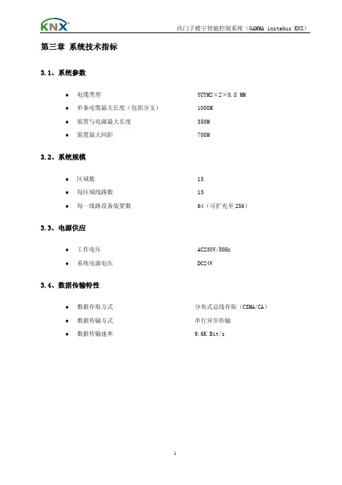
第三章 系统技术指标3.1、系统参数♦电缆类型 YCYM2×2×0.8 MM♦单条电缆最大长度(包括分支) 1000M♦装置与电源最大长度 350M♦装置最大间距 700M3.2、系统规模♦区域数 15♦每区域线路数 15♦每一线路设备装置数 64(可扩充至256)3.3、电源供应♦工作电压 AC230V/50Hz♦系统电源电压 DC24V3.4、数据传输特性♦数据存取方式 分布式总线存取(CSMA/CA)♦数据传输方式 串行异步传输♦数据传输速率 9.6K Bit/s第四章 系统详细配置4.1、系统架构照明监控管理系统主要包括照明监控工作站、网络连接控制器、单元控制继电器(控制器)、就地开关、各类传感器等。
单元控制器采用KNX/EIB现场总线连接,控制面板及各类传感器通过可编址控制EIB总线接入单元控制器或直接就近接入单元控制器,控制面板与建筑装修相协调。
系统架构拓扑示意图4.2、系统网络采用完全分布式集散控制系统(KNX/EIB),集中监控,分区控制,管理分级,通过网络系统将分布在各现场的控制器联接起来,软件与硬件分散配置。
中央停止工作不影响各分区功能和设备运行,网络通信控制也不应因此而中断。
系统分区控制完全独立,互不干扰,一个分区停止工作不影响其他分区和设备的正常运行;任意分区中任意器件损坏也不影响本区内其他器件正常工作;分区通信线路的中断不影响分区的正常运行。
分区模块化结构,支路控制,控制和调节功能由就地控制面板完成。
4.3、系统配置及技术参数参见附件《设备技术参数表》第五章 施工工艺描述5.1、KNX/EIB布线要求5.1.1.EIB线为24v低压信号线,需要单独配管,且与强电管之间的间距应大于、等于50mm,可与强电管平行铺设。
5.1.2.各个EIB开关、执行器元件都需使用标准EIB线缆连接,EIB线缆由厂商统一供应。
5.1.3.EIB线的连接结构形式多种多样,可选用星型、环型、总线型、网络型等多种连接形式,也可以互相混合使用,只需将EIB线连接到每个开关、感应器元件即可。


K-BUS ®KNX IP 路由器KNX IP Router_V1.3BNIPR-00/00.1KNX/EIB 住宅和楼宇智能控制系统使用手册目录第一章概述------------------------------------------------------------------------------------------------------------------------------------------------1 1.1.功能概述------------------------------------------------------------------------------------------------------------------------------------------1 1.2.通道------------------------------------------------------------------------------------------------------------------------------------------------2 1.3.路由------------------------------------------------------------------------------------------------------------------------------------------------2 1.4.KNX IP路由器-----------------------------------------------------------------------------------------------------------------------------------3第二章技术参数&尺寸图和操作指示--------------------------------------------------------------------------------------------------------------3 2.1.技术参数------------------------------------------------------------------------------------------------------------------------------------------3 2.2.尺寸图(单位:mm)---------------------------------------------------------------------------------------------------------------------------4 2.3.指示和操作功能---------------------------------------------------------------------------------------------------------------------------------5第三章项目设计和应用--------------------------------------------------------------------------------------------------------------------------------6 3.1.操作模式------------------------------------------------------------------------------------------------------------------------------------------63.1.1.LED指示------------------------------------------------------------------------------------------------------------------------------------63.1.2.功能按钮------------------------------------------------------------------------------------------------------------------------------------63.1.3.编程按钮和LED--------------------------------------------------------------------------------------------------------------------------6 3.2.IP路由应用---------------------------------------------------------------------------------------------------------------------------------------73.2.1.IP网络中的KNX报文------------------------------------------------------------------------------------------------------------------73.2.2.IP路由器在网络安装中------------------------------------------------------------------------------------------------------------------73.2.3.IP路由器作为域耦合器使用-----------------------------------------------------------------------------------------------------------83.2.4.IP路由器使用在混合系统中-----------------------------------------------------------------------------------------------------------83.2.5.IP路由器作为线耦合器使用-----------------------------------------------------------------------------------------------------------9第四章ETS中系统参数设置说明-------------------------------------------------------------------------------------------------------------------104.1.物理地址配置----------------------------------------------------------------------------------------------------------------------------------10 4.2.参数界面“General”-----------------------------------------------------------------------------------------------------------------------11 4.3.参数界面“IP configuration”-------------------------------------------------------------------------------------------------------------12 4.4.参数界面“KNX Multicasting Address”----------------------------------------------------------------------------------------------13 4.5.参数界面“Main Line”---------------------------------------------------------------------------------------------------------------------14 4.6.参数界面“Sub Line”----------------------------------------------------------------------------------------------------------------------15第五章网页配置----------------------------------------------------------------------------------------------------------------------------------------17 5.1.访问网页端的方式----------------------------------------------------------------------------------------------------------------------------175.1.1.通过windows网络访问---------------------------------------------------------------------------------------------------------------175.1.2.通过IP地址访问------------------------------------------------------------------------------------------------------------------------185.1.3.通过MAC地址访问--------------------------------------------------------------------------------------------------------------------18 5.2.设备信息-----------------------------------------------------------------------------------------------------------------------------------------19 5.3.KNX-----------------------------------------------------------------------------------------------------------------------------------------------19 5.4.Update--------------------------------------------------------------------------------------------------------------------------------------------20 5.5.IP tunneling地址分配------------------------------------------------------------------------------------------------------------------------23第六章出厂状态----------------------------------------------------------------------------------------------------------------------------------------25第一章概述IP路由器可用作线耦合器或骨干耦合器。
施耐德电气KNX/EIB系统设计手册2008现代社会随着计算机技术、网络技术、通讯技术的发展, 智能建筑的概念逐渐深入人们的生活。
人们对建筑的要求有了进一步的提升,除了传统需求,舒适性,安全性,高效性,方便性,可靠性甚至节能性都在考虑范围内,这使得智能建筑控制系统成为必然趋势。
施耐德电气KNX/EIB系统对灯光、空调及遮阳的自动监控功能,满足了使用者对智能资源的使用和管理需要,先进的软硬件设施为使用者和管理者提供了舒适宜人的生活意境和灵活高效的办公环境。
目 录第一章 KNX/EIB系统简介 /3第二章 KNX/EIB系统设计例图 /7第三章 KNX/EIB系统与BA的连接方法 /11第四章 KNX/EIB系统施工说明 /12第五章 KNX/EIB选型一览表 /13第六章 KNX/EIB系统部分业绩 /223第一章 KNX/EIB系统简介KNX/EIB系统的概念 "KNX/EIB系统"概念起源于二十世纪90年代,现已成为国际标准ISO/IEC14543-3,并于2007年正式成为中国HBES国标GB/Z 20965-2007。
该系统通过一条总线将所有的元器件连接起来,每个元器件均可独立工作,同时又可通过中控电脑进行集中监视和控制。
通过电脑编程的各元件既可独立完成诸如开关、控制、监视等工作,又可根据要求进行不同组合,从而实现不增加元件数量而功能却可灵活改变的效果。
施耐德电气KNX/EIB系统就是此类产品中的佼佼者。
KNX/EIB系统的优点:(1)集成控制。
可对灯光、遮阳、空调、地暖等进行集成式控制。
(2)舒适。
创造了安全,健康,宜人的生活及工作环境。
(3)节能。
现代化住宅应在满足使用者对环境要求的前提下,尽量利用自然光及人员活动来调节室内照明环境和温度环境,最大限度减少能量消耗。
(4)灵活。
能满足多种用户对不同环境功能的要求。
KNX/EIB系统是开放式,大跨度框架结构,允许用户迅速而方便地改变建筑物的使用功能或重新规划建筑平面。
KNX系统的概念"KNX系统"概念起源于二十世纪90年代,现已成为国际标准ISO/IEC14543-3,并于2007年正式成为中国HBES国标GB/Z20965-2007。
该系统通过一条总线将所有的元器件连接起来,每个元器件均可独立工作,同时又可通过中控电脑进行集中监视和控制。
通过电脑编程的各元件既可独立完成诸如开关、控制、监视等工作,又可根据要求进行不同组合,从而实现不增加元件数量而功能却可灵活改变的效果。
施耐德电气KNX系统就是此类产品中的佼佼者。
KNX原理示意图KNX系统的优点:(1)集成控制。
可对灯光、遮阳、空调、地暖等进行集成式控制。
(2)舒适。
创造了安全,健康,宜人的生活及工作环境。
(3)节能。
现代化住宅应在满足使用者对环境要求的前提下,尽量利用自然光及人员活动来调节室内照明环境和温度环境,最大限度减少能量消耗。
(4)灵活。
能满足多种用户对不同环境功能的要求。
KNX/EIB系统是开放式,大跨度框架结构,允许用户迅速而方便地改变建筑物的使用功能或重新规划建筑平面。
(5)经济。
自动化提供了实现节能运行与管理的必要条件,同时可大量减少管理与维护人员,降低管理费用,提高劳动效率,并提高管理水平。
(6)安全。
可与消防系统进行联动,当消防报警时,可将正常照明回路强行切断,应急回路强行点亮,从而降低火灾的风险,提高建筑的安全性。
系统元件160mA电源供应器MTN684016电源电压:AC320V,50-60Hz输出电压:DC29V±1V输出电流:最大160mA,防短路模块宽度:5模数=约90mm可为一条最多可带32个总线设备的线路提供总线电压内置扼流器,用于隔离总线的供电带开关,用于中断电压并复位连接在线路上的总线设备640mA电源供应器MTN684064电源电压:AC320V,50-60Hz输出电压:DC29V±1V输出电流:最大640mA,防短路模块宽度:7模数=约126mm可为一条最多可带64个总线设备的线路提供总线电压内置扼流器,用于隔离总线的供电带开关,用于中断电压并复位连接在线路上的总线设备640mA电源供应器(可接应急电源模块) MTN683890电源电压:AC320V,50-60Hz输出电压:DC29V±1V输出电流:最大640mA,防短路模块宽度:7模数=约126mm可为一条最多可带64个总线设备的线路提供总线电压内置扼流器,可以隔离电源带开关,用于中断电压并复位连接在线路上的总线设备可连接应急电源REG,以便为总线电压提供缓冲KNX/IP路由器MTN680329电源电压:DC12-30V(在DC24V 40mA),AC12-24V模块宽度:2模数=约36mm可作为快速干线在不同支线之间通过局域网(IP)转发报文控制信号也可用作编程接口,将PC与KNX总线连接起来能够双向转发报文控制信号,最多可对150个控制信号报文进行缓冲处理支线耦合器MTN680204模块宽度:2模数=约36mm可用于支线和区域的逻辑连接和电流隔离逻辑模块676029电流消耗:正常运行情况下约40mA,编程运行情况下约100mA模块宽度:3模数=约54mm内置实时定时器按照设定时间标准完成控制操作可以用一个功能元件库根据实际需求制定出通用的应用程序逻辑模块编程软件615014可用功能模块工具软件来编制功能模块REG的应用程序对PC的要求:需有一个空闲的串行接口接口/网关USB接口(导轨安装) MTN681829模块宽度:2模数=约36mm用于将编程设备或诊断设备通过USB1.1或USB2接口连接到INSTAUSEIB上总线的链接通过一个总线连接端子完成,无需数据导轨数据条内置总线耦合器电话网关MTN680790供电电源:DC 12-24V功耗:90mA/24V(开路),790mA at 24V(最大负荷)开关输出:6个,100mA/12V/24V报警输出:1个,100mA/12V/24V信号输入:6个,干接点电话:模拟,CTR21,线长3米RS 232:线长3米模块宽度:8模数=约144mm电话网关用于连接电话和KNX系统或传统的输入/输出最多可控制或显示20个KNX设备控制面板M系列2键智能面板带耦合器MTN627519(纯白)/MTN627514(烟灰)/MTN627560(银灰)内置总线耦合器本面板带有运行指示灯、状态指示灯、标签和2个操作按键防护顶盖为热塑材料,磨光功能:开关、转换、调光、百叶帘、脉冲发送出1、2、4或8为控制信号、2字节控制信号脉冲、8为推移式调节器、场景调用、场景存储、联锁功能防护顶盖为热塑材料,磨光功能:开关、转换、调光、百叶帘、脉冲发送出1、2、4或8为控制信号、2字节控制信号脉冲、8为推移式调节器、场景调用、场景存储、联锁功能8键智能面板带耦合器MTN627819(纯白)/MTN627814(烟灰)/MTN627860(银灰)内置总线耦合器本面板带有运行指示灯、状态指示灯、标签和8个操作按键防护顶盖为热塑材料,磨光功能:开关、转换、调光、百叶帘、脉冲发送出1、2、4或8为控制信号、2字节控制信号脉冲、8为推移式调节器、场景调用、场景存储、防乱按(防误操作)功能8键智能面板带耦合器带红外MTN627919(纯白)/MTN627914(烟灰)/MTN627960(银灰)内置总线耦合器本面板带有运行指示灯、状态指示灯、标签和8个操作按键每个按键的功能都可以使用一个IR远程控制器来触发防护顶盖为热塑材料,磨光功能:开关、转换、调光、百叶帘、脉冲发送出1、2、4或8为控制信号、2字节控制信号脉冲、8为推移式调节器、场景调用、场景存储、防乱按(防误操作)功能4键多功能面板带LCD温控MTN623244(奶白)/MTN623219(纯白)/MTN623214(烟灰)/MTN623260(银灰)本面板带有运行指示灯、状态指示灯、标签和4个操作按键带有室温控制单元和显示器防护顶盖为热塑材料,磨光多功能按键功能:开关、转换、调光、百叶帘、脉冲发送出1、2、4或8为控制信号、2字节控制信号脉冲、8为推移式调节器、场景调用、场景存储、联锁功能、带有同步化的定时控制、报警功能、周期读取外部温度值、风扇风机控制带有室温调控器和显示器带内置压电蜂鸣器,用于显示报警状态和红外线接收器每个按键的所有功能都可以通过远距离红外线遥控器进行操作防护顶盖为热塑材料,磨光多功能按键功能:开关、转换、调光、百叶帘、脉冲发送出1、2、4或8为控制信号、2字节控制信号脉冲、8为推移式调节器、场景调用、场景存储、联锁功能、带有同步化的定时控制、报警功能、周期读取外部温度值、风扇风机控制总线耦合器(温控面板用) MTN623299用于工作应用接口来连接室温调控器的多功能控制面板可用螺丝安装在60型安装底盒内安装深度:20mm单联翘板KNX连接单元MTN625199控制面板模块,不带面板。
T ebis EIB/KNX 智能控制系统设计应用手册Tebis EIB/KNX 智能控制系统设计应用手册目录11 11.Tebis EIB/KNX系统原理及结构1.1 Tebis EIB/KNX系统原理 1.2 Tebis EIB/KNX系统结构33 3 32. 系统实现的主要控制功能及优点2.1 Tebis系统主要的控制对象 2.2 Tebis系统主要的控制功能 2.3 Tebis系统的主要优点44 5 6 6 73. Tebis系统主要应用场合及控制方案3.1 大型建筑的公共区域3.2 会议室、多功能厅3.3 办公室3.4 酒店客房3.5 高档公寓及别墅88 13 174. 系统常用产品选型指导4.1 驱动器的选型4.2 面板及传感器的选型4.3 系统附件的选型2020 20 20 21 215. 系统设计常见疑点详解5.1 开关驱动器在配电箱中的表示方法 5.2 日光灯调光回路在配电箱中的表示方法5.3 窗帘控制的选型方案及参考图 5.4 风机盘管控制方案及参考图 5.5 消防联动的方案及参考图2222 23 24 256. Tebis设计图纸参考6.1 强电系统图6.2 系统拓扑图6.3 平面图6.4 设计实例解析277. Tebis部分成功项目1. Tebis EIB/KNX系统原理及结构1.1 Tebis EIB/KNX 系统原理Tebis系统是基于EIB/KNX总线标准的总线系统。
EIB/KNX系统是目前唯一认证为国际通用IEC标准(ISO/IEC 14543-3)和国家标准(GB/Z 20965-2007)的楼宇家居总线标准。
EIB/KNX系统的工作原理是利用信号控制线,即总线,把系统各个设备连接,通过软件编程,设定控制设备(面板、传感器、定时器等)和受控设备(开关驱动器、调光驱动器等) 之间的关系,包括控制设备所能控制受控设备的数量、方式、触发条件等等。
1.2 Tebis EIB/KNX 系统结构EIB/KNX系统的基本构成是由EIB/KNX元件通过总线连接成一条支线(Line),几条支线组成一个区域(Area),几个区域构成一个大的系统。