Cisco WLC+AP配置基础V1.0
- 格式:pdf
- 大小:2.61 MB
- 文档页数:31
思科路由器配置基础思科路由器配置基础思科(Cisco)路由器是智能信息网络的基础,为当今要求最严格的网络服务,包括IP 通信、视频、客户关系管理、金融交易和其他实时应用提供了高可用性、全面的安全性、易管理性和先进的服务质量( QoS )。
下面店铺准备了思科路由器配置基础,欢迎大家参考!一、基本设置方式一般来说,可以用5种方式来设置路由器:1.Console口接终端或运行终端仿真软件的微机;2.AUX口接MODEM,通过电话线与远方的终端或运行终端仿真软件的微机相连;3.通过Ethernet上的TFTP服务器;4.通过Ethernet上的TELNET程序;5.通过Ethernet上的SNMP网管工作站。
但路由器的第一次设置必须通过第一种方式进行,此时终端的硬件设置如下:波特率:9600数据位:8停止位:1奇偶校验: 无二、命令状态1. router>路由器处于用户命令状态,这时用户可以看路由器的连接状态,访问其它网络和主机,但不能看到和更改路由器的设置内容。
2. router#在router>提示符下键入enable,路由器进入特权命令状态router#,这时不但可以执行所有的用户命令,还可以看到和更改路由器的设置内容。
3. router(config)#在router#提示符下键入configure terminal,出现提示符router(config)#,此时路由器处于全局设置状态,这时可以设置路由器的全局参数。
4. router(config-if)#; router(config-line)#; router(config-router)#;…路由器处于局部设置状态,这时可以设置路由器某个局部的参数。
5. >路由器处于RXBOOT状态,在开机后60秒内按ctrl-break可进入此状态,这时路由器不能完成正常的功能,只能进行软件升级和手工引导。
6. 设置对话状态这是一台新路由器开机时自动进入的状态,在特权命令状态使用SETUP命令也可进入此状态,这时可通过对话方式对路由器进行设置。
CISCO路由器配置手册第一章路由器配置基础一、基本设置方式二、命令状态三、设置对话过程四、常用命令五、配置IP寻址六、配置静态路由第二章广域网协议设置一、HDLC二、PPP三、X.25四、Frame Relay五、ISDN六、PSTN第三章路由协议设置一、RIP协议二、IGRP协议三、OSPF协议四、重新分配路由五、IPX协议设置第四章服务质量及访问控制一、协议优先级设置二、队列定制三、访问控制第五章虚拟局域网(VLAN)路由一、虚拟局域网(VLAN)二、交换机间链路(ISL)协议三、虚拟局域网(VLAN)路由实例第一章路由器配置基础一、基本设置方式一般来说,可以用5种方式来设置路由器:1.Console口接终端或运行终端仿真软件的微机;2.AUX口接MODEM,通过电话线与远方的终端或运行终端仿真软件的微机相连;3.通过Ethernet上的TFTP服务器;4.通过Ethernet上的TELNET程序; 5.通过Ethernet上的SNMP网管工作站。
但路由器的第一次设置必须通过第一种方式进行,此时终端的硬件设置如下:波特率:9600数据位:8停止位:1奇偶校验: 无二、命令状态1. router>路由器处于用户命令状态,这时用户可以看路由器的连接状态,访问其它网络和主机,但不能看到和更改路由器的设置内容。
2. router#在router>提示符下键入enable,路由器进入特权命令状态router#,这时不但可以执行所有的用户命令,还可以看到和更改路由器的设置内容。
3. router(config)#在router#提示符下键入configure terminal,出现提示符router(config)#,此时路由器处于全局设置状态,这时可以设置路由器的全局参数。
4. router(config-if)#; router(config-line)#;router(config-router)#;…路由器处于局部设置状态,这时可以设置路由器某个局部的参数。

无线配置手册WLC配置手册基本配置1.初始设置连接到WLC的console口,启动超级终端或其它终端软件,把com口属性设置还原为默认值(如下图),点确定应用配置回车进入命令行管理界面选择5,清除原有设置,并进行初始设置Welcome to the Cisco Wizard Configuration ToolUse the '-' character to backupSystem Name [Cisco_40:4a:03]: C1-CONTROLLER-01Enter Administrative User Name (24 characters max): adminEnter Administrative Password (24 characters max):minshenmaService Interface IP Address Configuration [none][DHCP]: 192.168.1.1 Management Interface IP Address: 10.1.128.101Management Interface Netmask: 255.255.255.0Management Interface Default Router: 10.1.128.254Management Interface VLAN Identifier (0 = untagged): 128 Management Interface DHCP Server IP Address:10.1.32.1AP Manager Interface IP Address: 10.1.128.103AP Manager Interface DHCP Server : 10.1.32.1AP Transport Mode [Layer2] [Layer3]: Layer3Virtual Gateway IP Address: 10.254.100.101Mobility/RF Group Name: wukuangNetwork Name (SSID): managementAllow Static IP Addresses [YES][no]: yesConfigure a RADIUS Server now? [YES][no]: noEnable 802.11b Network [YES][no]: yesEnable 802.11a Network [YES][no]: yesEnable 802.11g Network [YES][no]: yesEnable Auto-RF [YES][no]: yesConfiguration saved!Resetting system with new configuration...至此,WLC初始设置完成。
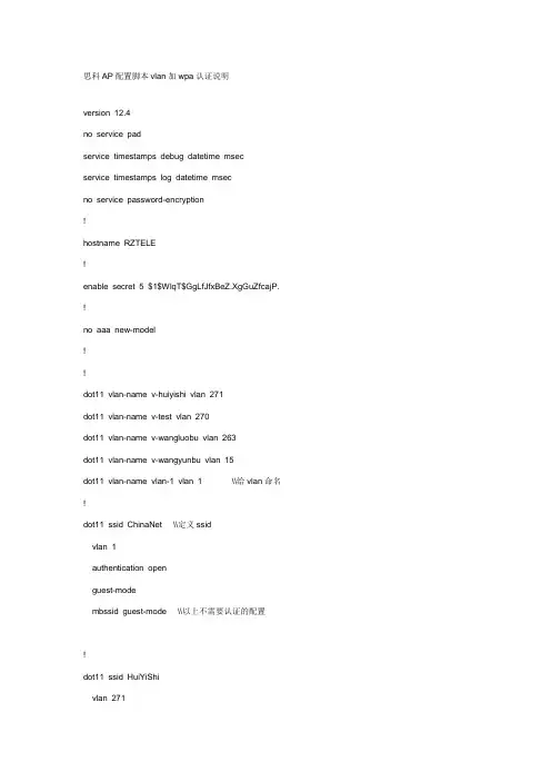
思科AP配置脚本vlan加wpa认证说明version 12.4no service padservice timestamps debug datetime msecservice timestamps log datetime msecno service password-encryption!hostname RZTELE!enable secret 5 $1$WlqT$GgLfJfxBeZ.XgGuZfcajP. !no aaa new-model!!dot11 vlan-name v-huiyishi vlan 271dot11 vlan-name v-test vlan 270dot11 vlan-name v-wangluobu vlan 263dot11 vlan-name v-wangyunbu vlan 15dot11 vlan-name vlan-1 vlan 1 \\给vlan命名!dot11 ssid ChinaNet \\定义ssidvlan 1authentication openguest-modembssid guest-mode \\以上不需要认证的配置!dot11 ssid HuiYiShivlan 271authentication openauthentication key-management wpa version 2mbssid guest-modewpa-psk ascii 0 1234567890 \\以上是wpa认证的配置!dot11 ssid WangLuobuvlan 263authentication openmbssid guest-mode!dot11 ssid WangYunBuvlan 15authentication openauthentication key-management wpa version 2mbssid guest-modewpa-psk ascii 0 wangyunbu.pass!!!username Cisco privilege 15 password 0 123456!bridge irb!!interface Dot11Radio0no ip addressno ip route-cache!encryption mode ciphers tkip!encryption vlan 15 mode ciphers tkip!encryption vlan 270 mode ciphers tkip!encryption vlan 271 mode ciphers tkip \\wpa认证的加密配置!ssid ChinaNet!ssid HuiYiShi!ssid WangLuobu!ssid WangYunBu \\将ssid应用到端口上!mbssid \\启用多ssid功能station-role root!interface Dot11Radio0.1encapsulation dot1Q 1no ip route-cache!interface Dot11Radio0.15encapsulation dot1Q 15 native \\配置管理vlan要加上nativeip address 172.20.63.30 255.255.255.0no ip route-cachebridge-group 1 \\选择组别(范围是1-255),要和下面的interface FastEthernet0.15一致bridge-group 1 port-protectedbridge-group 1 block-unknown-sourceno bridge-group 1 source-learningno bridge-group 1 unicast-floodingbridge-group 1 spanning-disabled!interface Dot11Radio0.263encapsulation dot1Q 263ip address 172.20.62.109 255.255.255.240 no ip route-cachebridge-group 255bridge-group 255 subscriber-loop-control bridge-group 255 port-protectedbridge-group 255 block-unknown-source no bridge-group 255 source-learningno bridge-group 255 unicast-flooding bridge-group 255 spanning-disabled!interface Dot11Radio0.270encapsulation dot1Q 270no ip route-cachebridge-group 254bridge-group 254 subscriber-loop-control bridge-group 254 port-protectedbridge-group 254 block-unknown-source no bridge-group 254 source-learningno bridge-group 254 unicast-flooding bridge-group 254 spanning-disabled!interface Dot11Radio0.271no ip route-cachebridge-group 253bridge-group 253 subscriber-loop-control bridge-group 253 port-protectedbridge-group 253 block-unknown-source no bridge-group 253 source-learningno bridge-group 253 unicast-flooding bridge-group 253 spanning-disabled!interface FastEthernet0no ip addressno ip route-cachespeed 100full-duplex!interface FastEthernet0.1 encapsulation dot1Q 1no ip route-cache!interface FastEthernet0.15 encapsulation dot1Q 15 nativeip address dhcpno ip route-cachebridge-group 1no bridge-group 1 source-learning bridge-group 1 spanning-disabled!interface FastEthernet0.263ip address 172.20.62.110 255.255.255.240no ip route-cachebridge-group 255no bridge-group 255 source-learningbridge-group 255 spanning-disabled!interface FastEthernet0.270encapsulation dot1Q 270no ip route-cachebridge-group 254no bridge-group 254 source-learning!interface FastEthernet0.271encapsulation dot1Q 271ip address dhcpno ip route-cachebridge-group 253no bridge-group 253 source-learningbridge-group 253 spanning-disabled!interface BVI1ip address 172.20.63.8 255.255.255.0 \\配置管理vlan的ip地址no ip route-cache!ip http serverno ip http secure-serverip http help-path /warp/public/779/smbiz/prodconfig/help/eag no cdp runbridge 1 route ip !!!line con 0 password Cisco line vty 0 4 password Cisco login!end。
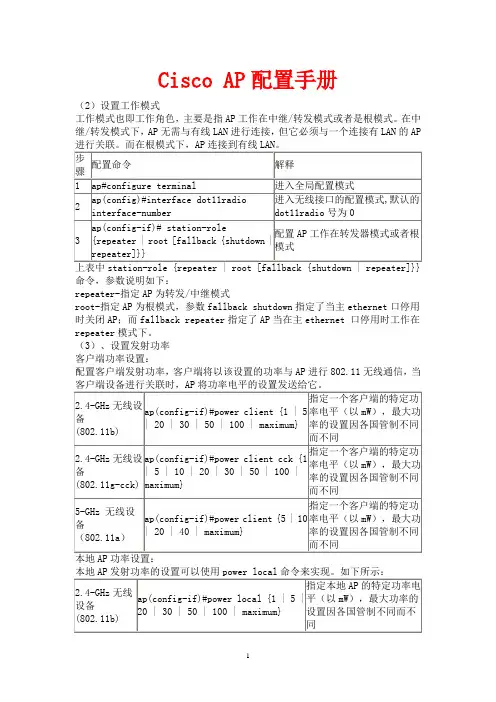
Cisco AP 配置手册(2)设置工作模式工作模式也即工作角色,主要是指AP 工作在中继/转发模式或者是根模式。
在中继/转发模式下,AP 无需与有线LAN 进行连接,但它必须与一个连接有LAN 的AP命令,参数说明如下:repeater-指定AP 为转发/中继模式root-指定AP 为根模式,参数fallback shutdown 指定了当主ethernet 口停用时关闭AP ;而fallback repeater 指定了AP 当在主ethernet 口停用时工作在repeater 模式下。
(3)、设置发射功率 客户端功率设置:配置客户端发射功率,客户端将以该设置的功率与AP 进行802.11无线通信,当可以使用CCK功率等级,CCK(补充编码键控)模式下可以由IEEE802.11b和IEEE802.11g设备来支持,而OFDM模式下可以由IEEE802.11a和IEEE802.11g 设备来支持。
举例说明:配置指定客户端发射功率为20mW:ap(config-if)# power client 20配置指定本地AP发射功率为20mW:ap(config-if)# power local 20speed {[1.0] [2.0] [5.5]…中可选参数的设置是指允许AP使用非基本设置,即AP只以这些速率发送单播包;speed [basic-1.0] [basic-2.0]…中可选参数的设置是指允许AP使用基本设置来发送所有单播和组播数据包。
至少一个AP的速率必须被配置为基本设置。
[rang]可选参数是指设置数据速率以获得最佳范围。
[throughput]可选参数是指设置数据率以获得最佳吞吐量。
[default]可选参数是指将数据率设置为默认。
注意:IEEE802.11g无线功率在上升至100mW时,可以达到1M,2M,5.5M和11M的速度;对于6M,9M,12M,18M,24M,36M,48M和54Mbps数据速率,可以在802.11g 最大无线功率为30mW时实现。


拓扑结构:ADSL---路由器----交换机----无线APAP只做无线接入,客户端接入到AP后,IP地址由交换机DHCP服务提供,DHCP配置略第一步:拿到设备后用console线连接PC,超级终端登录,enable密码通常默认为:Cisco (注意大小写)第二步:设置BVI地址。
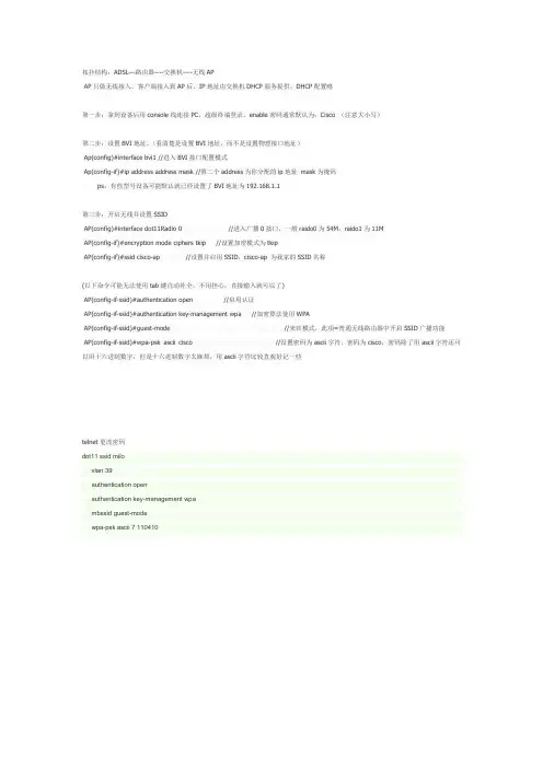
(看清楚是设置BVI地址,而不是设置物理接口地址)Ap(config)#interface bvi1 //进入BVI接口配置模式Ap(config-if)#ip address address mask //第二个address为你分配的ip地址mask为掩码ps:有些型号设备可能默认就已经设置了BVI地址为192.168.1.1第三步:开启无线并设置SSIDAP(config)#interface dot11Radio 0 //进入广播0接口,一般raido0为54M,raido1为11MAP(config-if)#encryption mode ciphers tkip //设置加密模式为tkipAP(config-if)#ssid cisco-ap //设置并启用SSID,cisco-ap 为我家的SSID名称(以下命令可能无法使用tab键自动补全,不用担心,直接输入就可以了)AP(config-if-ssid)#authentication open //启用认证AP(config-if-ssid)#authentication key-management wpa //加密算法使用WPAAP(config-if-ssid)#guest-mode //来宾模式,此项=普通无线路由器中开启SSID广播功能AP(config-if-ssid)#wpa-psk ascii cisco //设置密码为ascii字符,密码为cisco,密码除了用ascii字符还可以用十六进制数字,但是十六进制数字太麻烦,用ascii字符比较直观好记一些telnet更改密码dot11 ssid milovlan 39authentication openauthentication key-management wpambssid guest-modewpa-psk ascii 7 110410。

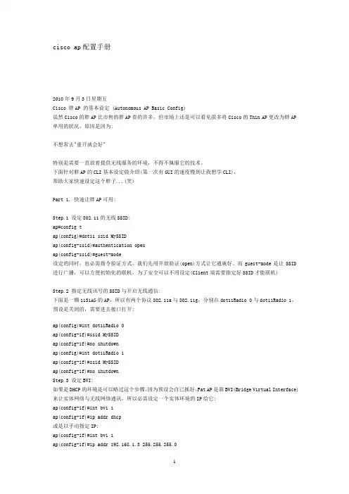
cisco ap配置手册2010年9月3日星期五Cisco 胖AP 的基本设定 (Autonomous AP Basic Config)虽然Cisco的胖AP比市售的胖AP贵的许多,但市场上还是可以看见很多将Cisco的Thin AP更改为胖AP 单用的状况,原因是因为:不想常去"重开就会好"特别是需要一直放着提供无线服务的环境,不得不佩服它的技术。
下面针对胖AP的CLI基本设定做介绍(第一次有GUI的速度慢到让我想学CLI),帮助大家快速设定这个胖子...(笑)Part 1. 快速让胖AP可用:Step.1 设定802.11的无线SSID:ap#config tap(config)#dot11 ssid MySSIDap(config-ssid)#authentication openap(config-ssid)#guest-mode设定的同时,也必需指令验证方式,我们先用开放验证(open)方式让它通就好。
而guest-mode是让SSID 进行广播,可以方便初始化的联机,为了安全可以不用设定(Client端需要指定好SSID才能联机)Step.2 指定无线讯号的SSID与开启无线通信:下面是一颗1131AG的AP,所以有两个协议802.11a与802.11g,分别在dot11Radio 0与dot11Radio 1,预设是关闭的,需要进去接口打开:ap(config)#int dot11Radio 0ap(config-if)#ssid MySSIDap(config-if)#no shutdownap(config)#int dot11Radio 1ap(config-if)#ssid MySSIDap(config-if)#no shutdownStep.3 设定BVI:如果是DHCP的环境是可以略过这个步骤,因为预设会自已抓好,Fat AP是靠BVI(Bridge Virtual Interface)来让实体网络与无线网络通讯,所以必需设定一个实体环境的IP给它:ap(config-if)#int bvi 1ap(config-if)#ip addr dhcp或是以手动指定IP:ap(config-if)#int bvi 1ap(config-if)#ip addr 192.168.1.3 255.255.255.0搞定!!把自已的计算机利用无线连看看!!Part 2. 常用基本设定:ARP Cache:AP的运作就像Hub一样,广播是它们必做的事,开启Arp-Cache,可以加快效能(虽然感受不到),当AP收到一个ARP封包,会比对Cache里的数据,如果不在Cache就不广播把封包丢掉,以减少广播封包。
cisco⽆线控制配置说明ContentsIntroductionPrerequisitesRequirementsComponents UsedConventionsBackground InformationConfigureNetwork DiagramConfigure the WLC for Basic OperationConfigure the Switch for the WLCConfigure the Switch for the APsVerifyTroubleshootCommandsController Does Not Defend AP-Manager IP AddressTroubleshoot a Lightweight Access Point Not Joininga Wireless LAN ControllerCisco Support Community - Featured ConversationsRelated InformationIntroductionThis document provides a basic configuration example of a lightweight access point (AP) that is connected to a Cisco Wireless LAN (WLAN) Controller (WLC) through a Cisco Catalyst Switch.PrerequisitesRequirementsEnsure that you meet these requirements before you attempt this configuration:Basic knowledge of the configuration of lightweight APs and Cisco WLCsBasic knowledge of Lightweight AP Protocol (LWAPP)Knowledge of the configuration of an external DHCP server and/or domain name server (DNS)Basic configuration knowledge of Cisco switchesComponents UsedThe information in this document is based on these software and hardware versions:Cisco Aironet 1232AG Series Lightweight APCisco 4402 Series WLC that runs firmware 5.2.178.0Microsoft Windows Server 2003 Enterprise DHCP serverThis configuration works with any other Cisco WLC and any lightweight AP.The information in this document was created from the devices in a specific lab environment. All of the devices used in this document started with a cleared (default) configuration. If your network is live, make sure that you understand the potential impact of any command.ConventionsRefer to the Cisco Technical Tips Conventions for more information on document conventions.Background InformationIn order for the WLC to be able to manage the LAP, the LAP should discover the controller and register with the WLC. There are different methods that an LAP uses in order to discover the WLC. For detailed information on the different methods the LAPs use to register to the WLCs, refer to Lightweight AP (LAP) Registration to a Wireless LAN Controller (WLC)This document describes the configuration steps needed to register the LAP to the WLC and for basic operation of the LWAPP wireless network.ConfigureIn order to register the LAP to the WLC and for basic operation of the LWAPP wireless network, complete these steps:1.Have a DHCP server present so that the APs can acquire a networkaddress.Note: Option 43 is used if the APs reside in a different subnet.2.Configure the WLC for basic operation.3.Configure the switch for the WLC.4.Configure the switch for the APs.5.Register the lightweight APs to the WLCs.Note: Use the Command Lookup Tool (registered customers only) in order to obtain more information on the commands used in this section.Network DiagramThis document uses this network setup:Configure the WLC for Basic OperationWhen the controller boots at factory defaults, the bootup script runs the configuration wizard, which prompts the installer for initial configuration settings. This procedure describes how to use the configuration wizard on the command-line interface (CLI) in order to enter initial configuration settings.Note: Be sure that you understand how to configure an external DHCP server and/or DNS.Complete these steps in order to configure the WLC for basicoperation:1.Connect your computer to the WLC with a DB-9 null modem serial cable.2.Open a terminal emulator session with these settings:o9600 baudo8 data bitso 1 stop bito No parityo No hardware flow control3.At the prompt, log in to the CLI.The default username is admin, and the default password is admin.4.If necessary, enter reset system in order to reboot the unit andstart the wizard.5.At the first wizard prompt, enter a system name. The system namecan include up to 32 printable ASCII characters.6.Enter an administrator user name and password. The user name andpassword can include up to 24 printable ASCII characters.7.Enter the service-port interface IP configuration protocol, eithernone or DHCP.Enter none if you do not want to use the service port or if you want to assign a static IP address to the service port. 8.If you entered none in step 7 and need to enter a static IP addressfor the service port, enter the service-port interface IP address and netmask for the next two prompts.If you do not want to use the service port, enter 0.0.0.0 for the IP address and netmask.9.Enter values for these options:o Management interface IP addresso Netmasko Default router IP addresso Optional VLAN identifierYou can use a valid VLAN identifier or 0 for untagged.10.Note: When the management interface on the controller isconfigured as part of the 'native vlan' on the switchport to which it connects, the controller should NOT tag the frames. Therefore, you must set the VLAN to be zero (on the controller).11.Enter the Network Interface (Distribution System) Physical Portnumber.For the WLC, the possible ports are 1 through 4 for a front-panel gigabit Ethernet port.12.Enter the IP address of the default DHCP server that supplies IPaddresses to clients, the management interface, and theservice-port interface, if you use one.13.Enter the LWAPP Transport Mode, either LAYER2 or LAYER3.Note: If you configure the WLC 4402 via Wizard and select AP transport Mode LAYER2, the Wizard does not ask the details of AP Manager.14.Enter the Virtual Gateway IP Address.This address can be any fictitious, unassigned IP address, such as1.1.1.1, for the Layer 3 Security and Mobility managers to use.Note: Usually the Virtual Gateway IP Address that is used is a private address.15.Enter the Cisco WLAN Solution Mobility Group/RF Group name.16.Enter the WLAN 1 service set identifier (SSID) or network name.This identifier is the default SSID that lightweight APs use in order to associate to a WLC.17.Allow or disallow Static IP Addresses for clients.Enter yes in order to allow clients to supply their own IP addresses.Enter no in order to require clients to request an IP address froma DHCP server.18.If you need to configure a RADIUS server on the WLC, enter yes andenter this information:o RADIUS server IP addresso The communication porto The shared secretIf you do not need to configure a RADIUS server or you want to configure the server later, enter no.19.Enter a country code for the unit.Enter help in order to see a list of the supported countries.20.Enable and disable support for IEEE 802.11b, IEEE 802.11a, and IEEE802.11g.21.Enable or disable radio resource management (RRM) (auto RF).WLC 4402—Configuration WizardWelcome to the Cisco Wizard Configuration ToolUse the '-' character to backupSystem Name [Cisco_43:eb:22]: c4402Enter Administrative User Name (24 characters max): adminEnter Administrative Password (24 characters max): *****Service Interface IP Address Configuration [none][DHCP]: noneEnable Link Aggregation (LAG) [yes][NO]: No Management Interface IP Address:192.168.60.2Management Interface Netmask:255.255.255.0Management Interface Default Router: 192.168.60.1Management Interface VLAN Identifier (0 = untagged): 60Management Interface Port Num [1 to 2]: 1 Management Interface DHCP Server IP Address: 192.168.60.25AP Transport Mode [layer2][LAYER3]: LAYER3 AP Manager Interface IP Address:192.168.60.3AP-Manager is on Management subnet, using same valuesAP Manager Interface DHCP Server(192.168.50.3): 192.168.60.25Virtual Gateway IP Address: 1.1.1.1 Mobility/RF Group Name: RFgroupname Network Name (SSID): SSIDAllow Static IP Addresses [YES][no]: yes Configure a RADIUS Server now? [YES][no]: no Enter Country Code (enter 'help' for a list of countries) [US]: USEnable 802.11b Network [YES][no]: yes Enable 802.11a Network [YES][no]: yes Enable 802.11g Network [YES][no]: yes Enable Auto-RF [YES][no]: yesNote: The management interface on the WLC is the only consistently pingable interface from outside of the WLC. So it is an expected behavior if you are not able to ping the AP manager interface from outside of the WLC.Note: You must configure the AP manager interface in order for the APs to associate with the WLC.Configure the Switch for the WLCThis example uses a Catalyst 3750 switch that uses only one port. The example tags the AP-manager and management interfaces and places these interfaces on VLAN 60. The switch port is configured as an IEEE 802.1Q trunk and only the appropriate VLANs, which are VLANs 2 through 4 and 60 in this case, are allowed on the trunk. The management and AP-manager VLAN (VLAN 60) is tagged and is not configured as the native VLAN of the trunk. So when the example configures those interfaces on the WLC, the interfaces are assigned a VLAN identifier.This is an example 802.1Q switch port configuration:interface GigabitEthernet1/0/1description Trunk Port to Cisco WLCswitchport trunk encapsulation dot1qswitchport trunk allowed vlan 2-4,60switchport mode trunkno shutdownNote: When you connect the WLC gigabit port, make sure it is connected to the switch gigabit port only. If you connect the WLC gigabit Ethernet to the Switch FastEthernet port then it will not work.Notice that this configuration example configures the neighbor switch port in a way that only allows relevant VLANs on the 802.1Q trunk. All other VLANs are pruned. This type of configuration is not necessary, but it is a deployment best practice. When you prune irrelevant VLANs, the WLC only processes relevant frames, which optimizes performance.Configure the Switch for the APsThis is an example VLAN interface configuration from the Catalyst 3750: interface VLAN5description AP VLANip address 10.5.5.1 255.255.255.0While the Cisco WLCs always connect to 802.1Q trunks, Cisco lightweight APs do not understand VLAN tagging and should only be connected to the access ports of the neighbor switch.This is an example switch port configuration from the Catalyst 3750:interface GigabitEthernet1/0/22description Access Port Connection to Cisco Lightweight APswitchport access vlan 5switchport mode accessno shutdownThe infrastructure is now ready for connection to the APs. The LAPs use the different WLC discovery methods and select a WLC to join. The LAP then registers with the controller.Here is a link to a video on the Cisco Support Community that explainsthe initial configuration of Wireless LAN Controller using the CLI and GUI: Initial configuration of Wireless LAN Controller using the CLI andGUIVerifyUse this section in order to confirm that your configuration works properly.After the LAPs register with the controller, you can view them under Wireless at the top of the user interface of the controller:On the CLI, you can use the show ap summary command in order to verify that the LAPs registered with the WLC: (Cisco Controller) >show ap summaryNumber of APs (1)Global AP User Name.............................. Not Configured Global AP Dot1x User Name........................ Not ConfiguredAP Name Slots AP Model Ethernet MAC Location Port Country Priority------------------ ----- ------------------- --------------------------------- ---- ------- ------AP001b.d4e3.a81b 2 AIR-LAP1232AG-A-K9 00:1b:d4:e3:a8:1b default location 2 IN 1On the WLC CLI, you can also use the show client summary command in order to see the clients that are registered with the WLC:(Cisco Controller) >show client summaryNumber of Clients (1)MAC Address AP Name Status WLAN Auth Protocol Port----------------- ------------- ------------- ---- ---- -------- ----00:40:96:a1:45:42 ap:64:a3:a0 Associated 4 Yes 802.11a 1(Cisco Controller) >Here is a video demonstration that explains how to perform the initial configuration of a Wireless LAN Controller using the GUI and CLI: InitialConfiguration of Wireless Lan Controller using CLI and GUITroubleshootUse this section in order to troubleshoot your configuration. CommandsUse these commands in order to troubleshoot your configuration.Note: Refer to Important Information on Debug Commands before you use debug commands.This debug lwapp events enable WLC command output shows that the lightweight AP gets registered to the WLC: (Cisco Controller) >debug lwapp events enableTue Apr 11 13:38:47 2006: Received LWAPP DISCOVERY REQUEST from AP00:0b:85:64:a3:a0 to ff:ff:ff:ff:ff:ff on port '1'Tue Apr 11 13:38:47 2006: Successful transmission of LWAPPDiscovery-Responseto AP 00:0b:85:64:a3:a0 on Port 1Tue Apr 11 13:38:58 2006: Received LWAPP JOIN REQUEST from AP00:0b:85:64:a3:a0 to 00:0b:85:33:a8:a0 on port '1'Tue Apr 11 13:38:58 2006: LWAPP Join-Request MTU path from AP00:0b:85:64:a3:a0is 1500, remote debug mode is 0Tue Apr 11 13:38:58 2006: Successfully added NPU Entry for AP00:0b:85:64:a3:a0 (index 48) Switch IP: 192.168.60.2, Switch Port: 12223,intIfNum 1, vlanId 60 AP IP: 10.5.5.10, AP Port: 19002, next hop MAC: 00:0b:85:64:a3:a0Tue Apr 11 13:38:58 2006: Successfully transmission of LWAPP Join-Reply to AP00:0b:85:64:a3:a0Tue Apr 11 13:38:58 2006: Register LWAPP event for AP00:0b:85:64:a3:a0 slot 0Tue Apr 11 13:38:58 2006: Register LWAPP event for AP 00:0b:85:64:a3:a0 slot 1Tue Apr 11 13:39:00 2006: Received LWAPP CONFIGURE REQUEST from AP00:0b:85:64:a3:a0 to 00:0b:85:33:a8:a0Tue Apr 11 13:39:00 2006: Updating IP info for AP 00:0b:85:64:a3:a0 -- static 0, 10.5.5.10/255.255.255.0, gtw 192.168.60.1 Tue Apr 11 13:39:00 2006: Updating IP 10.5.5.10 ===> 10.5.5.10 for AP 00:0b:85:64:a3:a0Tue Apr 11 13:39:00 2006: spamVerifyRegDomain RegDomain set for slot 0 code 0regstring -A regDfromCb -ATue Apr 11 13:39:00 2006: spamVerifyRegDomain RegDomain set for slot 1 code 0regstring -A regDfromCb -ATue Apr 11 13:39:00 2006: spamEncodeDomainSecretPayload:Send domain secretMobilityGroup<6f,39,74,cd,7e,a4,81,86,ca,32,8c,06,d3,ff,ec,6d,95,10,99,dd>to AP 00:0b:85:64:a3:a0Tue Apr 11 13:39:00 2006: Successfully transmission of LWAPPConfig-Message to AP 00:0b:85:64:a3:a0Tue Apr 11 13:39:00 2006: Running spamEncodeCreateVapPayload for SSID 'SSID'Tue Apr 11 13:39:00 2006: AP 00:0b:85:64:a3:a0 associated. Last AP failure wasdue to Configuration changes, reason: operator changed 11g mode Tue Apr 11 13:39:00 2006: Received LWAPP CHANGE_STATE_EVENT from AP 00:0b:85:64:a3:a0Tue Apr 11 13:39:00 2006: Successfully transmission of LWAPPChange-State-EventResponse to AP 00:0b:85:64:a3:a0Tue Apr 11 13:39:00 2006: Received LWAPP Up event for AP 00:0b:85:64:a3:a0 slot 0!Tue Apr 11 13:39:00 2006: Received LWAPP CONFIGURE COMMAND RES from AP 00:0b:85:64:a3:a0Tue Apr 11 13:39:00 2006: Received LWAPP CHANGE_STATE_EVENT from AP 00:0b:85:64:a3:a0Tue Apr 11 13:39:00 2006: Successfully transmission of LWAPPChange-State-EventResponse to AP 00:0b:85:64:a3:a0Tue Apr 11 13:39:00 2006: Received LWAPP Up event for AP00:0b:85:64:a3:a0 slot 1!This output shows these useful WLC debug commands:debug pem state enable—Configures the access policy manager debug optionsdebug pem events enabledebug dhcp message enable—Shows the debug of DHCP messages that are exchanged to and from the DHCP server debug dhcp packet enable—Shows the debug of DHCP packet details that are sent to and from the DHCP serverTue Apr 11 14:30:49 2006: Applied policy for mobile 00:40:96:a1:45:42 Tue Apr 11 14:30:49 2006: STA [00:40:96:a1:45:42,192.168.1.41] Replacing FastPath rule type = Airespace AP Client on AP 00:0B:85:64:A3:A0, slot 0InHandle = 0x00000000, OutHandle = 0x00000000 ACL Id = 255, Jumbo Frames= NO, interface = 1 802.1P = 0, DSCP = 0, TTue Apr 11 14:30:49 2006: Successfully plumbed mobile rule for mobile 00:40:96:a1:45:42 (ACL ID 255)Tue Apr 11 14:30:49 2006: Plumbed mobile LWAPP rule on AP00:0b:85:64:a3:a0for mobile 00:40:96:a1:45:42Tue Apr 11 14:30:53 2006: DHCP proxy received packet, src: 0.0.0.0, len = 320Tue Apr 11 14:30:53 2006: dhcpProxy: Received packet: Client00:40:96:a1:45:42DHCP Op: BOOTREQUEST(1), IP len: 320, switchport: 1, encap: 0xec03 Tue Apr 11 14:30:53 2006: dhcpProxy(): dhcp request, client:00:40:96:a1:45:42: dhcp op: 1, port: 1, encap 0xec03, old mscbport number: 1Tue Apr 11 14:30:53 2006: dhcp option len, including the magic cookie = 84Tue Apr 11 14:30:53 2006: dhcp option: received DHCP REQUEST msgTue Apr 11 14:30:53 2006: dhcp option: skipping option 61, len 7Tue Apr 11 14:30:53 2006: dhcp option: requested ip = 192.168.1.41 Tue Apr 11 14:30:53 2006: dhcp option: skipping option 12, len 15Tue Apr 11 14:30:53 2006: dhcp option: skipping option 81, len 19Tue Apr 11 14:30:53 2006: dhcp option: vendor class id = MSFT 5.0 (len 8)Tue Apr 11 14:30:53 2006: dhcp option: skipping option 55, len 11Tue Apr 11 14:30:53 2006: dhcpParseOptions: options end, len 84, actual 84Tue Apr 11 14:30:53 2006: mscb->dhcpServer: 192.168.60.2,mscb->dhcpNetmask:255.255.255.0,mscb->dhcpGateway: 192.168.60.1, mscb->dhcpRelay:192.168.60.2 VLAN: 60Tue Apr 11 14:30:53 2006: Local Address: 192.168.60.2, DHCP Server: 192.168.60.2, Gateway Addr: 192.168.60.2, VLAN: 60, port: 1Tue Apr 11 14:30:53 2006: DHCP Message Type received: DHCP REQUEST msg Tue Apr 11 14:30:53 2006: op: BOOTREQUEST, htype: Ethernet, hlen: 6, hops: 1Tue Apr 11 14:30:53 2006: xid: 3371152053, secs: 0, flags: 0Tue Apr 11 14:30:53 2006: chaddr: 00:40:96:a1:45:42Tue Apr 11 14:30:53 2006: ciaddr: 0.0.0.0, yiaddr: 0.0.0.0Tue Apr 11 14:30:53 2006: siaddr: 0.0.0.0, giaddr: 192.168.60.2Tue Apr 11 14:30:53 2006: Forwarding DHCP packet locally (348 octets) from 192.168.60.2 to 192.168.60.2Tue Apr 11 14:30:53 2006: Received 348 byte dhcp packet from 0x0201a8c0 192.168.60.2:68Tue Apr 11 14:30:53 2006: DHCP packet: 192.168.60.2 -> 192.168.60.2 using scope "InternalScope"Tue Apr 11 14:30:53 2006: received REQUESTTue Apr 11 14:30:53 2006: Checking node 192.168.1.41 Allocated 1144765719,Expires 1144852119 (now: 1144765853)Tue Apr 11 14:30:53 2006: adding option 0x35Tue Apr 11 14:30:53 2006: adding option 0x36Tue Apr 11 14:30:53 2006: adding option 0x33Tue Apr 11 14:30:53 2006: adding option 0x03Tue Apr 11 14:30:53 2006: adding option 0x01Tue Apr 11 14:30:53 2006: dhcpd: Sending DHCP packet(giaddr:192.168.60.2)to192.168.60.2:67 from 192.168.60.2:1067Tue Apr 11 14:30:53 2006: sendto (548 bytes) returned 548Tue Apr 11 14:30:53 2006: DHCP proxy received packet, src: 192.168.60.2, len = 548Tue Apr 11 14:30:53 2006: dhcpProxy: Received packet: Client00:40:96:a1:45:42DHCP Op: BOOTREPLY(2), IP len: 548, switchport: 0, encap: 0x0Tue Apr 11 14:30:53 2006: dhcp option len, including the magic cookie = 312Tue Apr 11 14:30:53 2006: dhcp option: received DHCP ACK msgTue Apr 11 14:30:53 2006: dhcp option: server id = 192.168.60.2Tue Apr 11 14:30:53 2006: dhcp option: lease time (seconds) = 86400 Tue Apr 11 14:30:53 2006: dhcp option: gateway = 192.168.60.1Tue Apr 11 14:30:53 2006: dhcp option: netmask = 255.255.255.0Tue Apr 11 14:30:53 2006: dhcpParseOptions: options end, len 312, actual 64Tue Apr 11 14:30:53 2006: DHCP Reply to AP client: 00:40:96:a1:45:42, frame len 412, switchport 1Tue Apr 11 14:30:53 2006: DHCP Message Type received: DHCP ACK msgTue Apr 11 14:30:53 2006: op: BOOTREPLY, htype: Ethernet, hlen: 6, hops: 0Tue Apr 11 14:30:53 2006: xid: 3371152053, secs: 0, flags: 0Tue Apr 11 14:30:53 2006: chaddr: 00:40:96:a1:45:42Tue Apr 11 14:30:53 2006: ciaddr: 0.0.0.0, yiaddr: 192.168.1.41Tue Apr 11 14:30:53 2006: siaddr: 0.0.0.0, giaddr: 0.0.0.0Tue Apr 11 14:30:53 2006: server id: 1.1.1.1 rcvd server id:192.168.60.2You can use these additional debug commands in order to troubleshoot your configuration:debug lwapp errors enable—Shows output of the debug of LWAPP errors debug pm pki enable—Shows the debug ofcertificate messages that are passed between the AP and the WLCController Does Not Defend AP-Manager IP AddressThis issues is a result of bug CSCsg75863. If the user accidently injects a device on the subnet that uses the AP-manager IP address of the controller, the Address Resolution Protocol (ARP) cache on the default gateway router is refreshed with the wrong MAC address. When this occurs, the APs can no longer reach the controller and drop into their discovery phase to look for a controller. The APs send discovery requests, and the controller responds with discovery replies, but the JOIN requests never reach the AP-manager interface of the controller because of the bad ARP entry on the gateway router. After the default 4 hour ARP refresh interval, the APs join the controller if the device is removed.A workaround for this issue is to configure the static ARP entries on the gateway router of the controller for these IP addresses:Management IP address—Customers gain access to the graphical user interface (GUI) from another subnet, and the controller receives the AP discovery requests.AP-Manager IP address—APs join the controller from another subnet.Every Dynamic interface IP address—Packets from other subnets reach the dynamic interface of the controller.DHCP packets transmit from the interface of the wireless client. Telnet or SSH to the gateway address of the controller, and use the arp command in order to add the ARP entries. Use the ping command on the default router of the controller to the different addresses in order to refresh the ARP cache on the router. In order to discover the MAC addresses, use this command: show arp | include .Troubleshoot a Lightweight Access Point Not Joining a Wireless LAN ControllerRefre to Troubleshoot a Lightweight Access Point Not Joining a Wireless LAN Controller for information on some of the issues why a Lightweight Access Point (LAP) fails to join a WLC and how to troubleshoot the issues.Cisco Support Community - Featured ConversationsCisco Support Community is a forum for you to ask and answer questions, share suggestions, and collaborate with your peers. Below are just some of the most recent and relevant conversations happening right now.。
无线配置手册WLC配置手册基本配置1.初始设置连接到WLC的console口,启动超级终端或其它终端软件,把com口属性设置还原为默认值(如下图),点确定应用配置回车进入命令行管理界面选择5,清除原有设置,并进行初始设置Welcome to the Cisco Wizard Configuration ToolSystem Name[Cisco_40:4a:03]:C1-CONTROLLER-01Enter Administrative User Name(24characters max):adminEnter Administrative Password(24characters max):minshenma Service Interface IP Address Configuration[none][DHCP]:192.168.1.1 Management Interface IP Address:10.1.128.101Management Interface Netmask:255.255.255.0Management Interface Default Router:10.1.128.254Management Interface VLAN Identifier(0=untagged):128 Management Interface DHCP Server IP Address:10.1.32.1AP Manager Interface IP Address:10.1.128.103AP Manager Interface DHCP Server:10.1.32.1AP Transport Mode[Layer2][Layer3]:Layer3Virtual Gateway IP Address:10.254.100.101Mobility/RF Group Name:wukuangNetwork Name(SSID):managementAllow Static IP Addresses[YES][no]:yesConfigure a RADIUS Server now?[YES][no]:noEnable802.11b Network[YES][no]:yesEnable802.11a Network[YES][no]:yesEnable802.11g Network[YES][no]:yesEnable Auto-RF[YES][no]:yesConfiguration saved!Resetting system with new configuration...至此,WLC初始设置完成。
Cisco思科无线AP的基本配置是什么CISCO无线AP的基础配置这里是一个无线AP的基本配置向导:Cisco Access Point Basic Config Manual首先,我们要先得用AP的Console口进去,给interface BVI1配置一个IP地址,CISCO的AP BVI接口IP地址出厂值为 10.0.0.1,默认用户名是cisco,密码Cisco(第一个C为大写);我们从配置模式进入BVI接口,做如下配置:interface BVI1ip address 192.168.123.201 255.255.255.01、修改无线SSID在IE浏览器地址栏中输入刚才配置的AP的管理地址(192.168.123.201),在认证对话框中输入管理密码,进入 AP的WEB 管理界面。
在左边的选项卡中,选择“EXPRESS SECURITY”,进入SSID管理界面。
输入新的SSID,记得勾选“Broadcast SSID in Beacon”选项,把SSID广播出去,否则在客户端的无线列表中,将看不到我们新建的SSID。
如果需要安全选项,请在3.Security设置。
2、启用无线接口AP的默认配置无线接口是关闭的,因此即使配置了SSID,我们还是在无线客户端上搜索不到这个SSID。
选择左边栏“Network Interfaces”--“Radio0-802.11G”(相信绝大部分用户都是用802.11G的),--Settings,我们可以看到当前的状态是“Disabled”和“Down”,把Enable Radio右边的单选项“Enable”勾选上,点击“Apply”,如果想快点看到效果,建议把AP重启一下。
接口的状态是下图这个样子就对了,无线AP就能正常工作,执行基本的无线AP的功能3.修改管理员密码选择“SECURITY”下的“Admin Access”,系统默认“Administrator Authenticate By: Default Authentication (Global Password)”,因此,我们在第二栏的“Default Authentication (Global Password)”修改管理员密码。
ciscoap配置手册详解的方法cisco ap配置手册Cisco AP的配置方法主要有控制台端口登录、远程登录(如Telnet/SSH 等)、Web浏览器等,后两中触均勰麺或iSB—个IP方可謀。
一般情况下,AP iSS. IP Ot 的方法有按默认方式觌,配置DHCP方式获取, 使用IPSU(IP Setup Utility),使用控制台端口等。
实际上对Cisco AP来讲,配置的最简单的方法就是使用Web浏览器方式即GUI 方式。
Cisco AP有廨基本GUI界面,一种是支持IOS GUI,如Arionet 1100 系列;一种是VxWorks GUI,如Arionet 350 的AP 和网桥; 而Arionet 1200系列可以支捋这两种GUI界面。
如下图Cisco Aironet 1100系列AP GUI配置界面:除了GUI和远程登录方式外,CLI(命令行)也是Cisco AP经常使用的配置方式。
GUI的配置方法比较简单,因篇幅所限,不再作介绍。
下面我们在CLI(命令行)模式下对Cisco AP进行配置。
Cisco AP的IOS的CLI(命令行)的配置模式有:用户模式、特权模式、全局模式、接口模式、线路模式等等,它的命令提示符、基本配置命令与基于Cisco IOS 系统的路由器和交换机CLI的模式也基本相同,如果您对各种模式还不熟悉,请您参照路由器和交换机的基本模式配置章节。
注意:hostname name命令中的name名称必须符合ARPANET主机名的规则,最多为63个字符,并且必须以一个字母开头,结尾必须是一个字母或数字,中间只能是字母、数字或连接符。
2、配置IP地址为了实现对设备的远程管理,我们通常需要对设备配置管理地址,对于AP来说,我们可以通过配置AP的BVI地址来实现。
BVI即网桥虚拟接口,它是由AP自动创建的,当AP连接到有线网络时,AP使用BVI 将所有接口都聚合到一个IP地址下,然后通过AP的以太网口和无线端口并使用该BVI 的地址对A P进行管理。