熔断器的使用维护
- 格式:doc
- 大小:14.00 KB
- 文档页数:1

熔断器安全操作及保养规程熔断器是一种重要的电气元器件,常用于电路的过载或短路保护,因此其安全操作和保养对于电气设备的安全和可靠运行至关重要。
本文将介绍关于熔断器的安全操作和保养规程。
1. 熔断器的分类和构造熔断器按照保护对象分为低压熔断器和高压熔断器两大类,按照熔丝材料分为玻璃熔断器、陶瓷熔断器和石墨熔断器三大类。
熔断器的主要构造包括熔丝、熔丝支架、熔断器座、动触头、静触头、弹簧和外壳等。
其中,熔丝是熔断器的核心组件,其材料和管径选用应根据电路的额定电压、额定电流和额定断路容量来确定。
2. 熔断器的安全操作2.1 使用前的检查在使用熔断器之前,应检查熔断器的参数是否与电路匹配,如额定电压、额定电流和额定断路容量等。
同时也要检查熔丝是否完好,是否有损伤,是否正确接装等。
2.2 安装姿态熔断器应采用垂直布置方式,以保证熔丝受力均匀,同时也便于熔丝融化后的及时断路。
2.3 过载运行熔断器在过载运行过程中,应显示出较大的热稳定性和电稳定性。
同时,当电流达到熔断器的额定电流时,熔丝应在规定时间内断开,保护电路不受过载损坏。
2.4 短路运行熔断器在和电气设备连续实施短路保护时,应显示出较强的电力热稳定性和机械强度。
同时,应在断路后迅速排除负载,并对熔断器进行更换维护。
2.5 使用后的检查在熔断器使用一定周期后,应对其进行检查和维护,包括检查熔丝是否完好、电器性能是否符合要求、触点是否干净、保护管是否破损等,以保证熔断器的正常使用。
3. 熔断器的保养规程3.1 清洁熔断器应定期清洁,以防止积尘和氧化物等对熔丝和触点的影响。
清洁时应使用干净柔软的布擦拭,不得使用涂料、清洗剂等含腐蚀性物质。
3.2 更换当熔断器失效或使用寿命结束时,应及时更换。
更换时应根据电路的额定电压、额定电流和额定断路容量等参数来进行匹配,同时也要注意更换过程中的安全保护。
3.3 保养熔断器在使用过程中,应根据现场使用情况和工作环境情况制定相应的保养方案。
O p e r at i O n a n dM a i n t e n a n c e M a n ua lf u s i b l es h u n t t r i p sw i tc h2 • Fusible Shunt Trip SwitchENCLOSED INDUSTRIAL CONTROL PANELFusible Shunt Trip SwitchDevice Overview . . . . . . . . . . . . . . . . . . . . . . . . . . . . . . . . . . . . . . . . . . . . . . . . . . . . . . . . . . . . . . . . . . . . . . . . . . . . . .2Installation Instructions . . . . . . . . . . . . . . . . . . . . . . . . . . . . . . . . . . . . . . . . . . . . . . . . . . . . . . . . . . . . . . . . . . . . . . . .3Catalog Number Selection T able . . . . . . . . . . . . . . . . . . . . . . . . . . . . . . . . . . . . . . . . . . . . . . . . . . . . . . . . . . . . . . . .4Motor Fuse Selection T able . . . . . . . . . . . . . . . . . . . . . . . . . . . . . . . . . . . . . . . . . . . . . . . . . . . . . . . . . . . . . . . . . . . . .5Wiring Diagram – 120VAC Control Interface . . . . . . . . . . . . . . . . . . . . . . . . . . . . . . . . . . . . . . . . . . . . . . . . . . . . . .6Wiring Diagram – 24V (AC or DC) Control Interface . . . . . . . . . . . . . . . . . . . . . . . . . . . . . . . . . . . . . . . . . . . . . .7T orque Specifications . . . . . . . . . . . . . . . . . . . . . . . . . . . . . . . . . . . . . . . . . . . . . . . . . . . . . . . . . . . . . . . . . . . . . . . . . .8Maintenance . . . . . . . . . . . . . . . . . . . . . . . . . . . . . . . . . . . . . . . . . . . . . . . . . . . . . . . . . . . . . . . . . . . . . . . . . . . . . . . . . .9Warranty . . . . . . . . . . . . . . . . . . . . . . . . . . . . . . . . . . . . . . . . . . . . . . . . . . . . . . . . . . . . . . . . . . . . . . . . . . . . . . . . . . . . .9FAQs (Frequently Asked Questions) . . . . . . . . . . . . . . . . . . . . . . . . . . . . . . . . . . . . . . . . . . . . . . . . . . . . . . . . . . . .9Spare Parts List . . . . . . . . . . . . . . . . . . . . . . . . . . . . . . . . . . . . . . . . . . . . . . . . . . . . . . . . . . . . . . . . . . . . . . . . . . . . . . .10D e V I C e O V e r V I e WFusible shunt trip disconnect switches are a required safety feature in many industrial and commercial applications. Main branch-circuit fuses provide overcurrent protection in the event of short-circuits, power surges, damage to electrical wiring, etc…by interrupting faulty circuitry and removing it from the electrical system. In addition, the molded case switch can disconnect power from the source prior to known electrical disturbances, before the fuse is required to operate. Integrated into the molded case switch is an electromagnet (shunt trip coil), controlling a spring-loaded conductivestrip which maintains continuity between the line side and load side terminals of the switch. The electromagnetic coil is normally connected to a safety system, such as a fire alarm or smoke detector housed in the surrounding building. Should there be an electrical emergency, a signal is sent to the coil (via the safety system, alarm, sprinkler, etc…) and the electromagnet would be engaged, throwing the switch and disconnecting power. Power can only then be reenergized by manually operating the molded case switch. • Fusible Shunt Trip Switch 3D A N g e r A N D WA r N I N g L A b e L SU L L I S T I N g I N F O r M AT I O NStep 1: Disconnect power from the circuit where the fusible shunt trip switch will be installed. Mount the panel. Wire up the line side three phase conductors into the three line side terminals of the molded case switch (L1, L2 and L3). Wire the load side to the three load side terminals of the class J fuseholder (T1, T2 and T3).Step 2: Wire the remote control elements to the specified terminal blocks shown in the wiring diagrams on page 6 and 7 (120VAC and 24VAC/DC respectively) of this manual. For 120VAC, safety system controls must supply a set of dry (no voltage) contacts. For 24VAC/DC, safety system controls must provide the voltage source.Step 3: Connect power to the circuit on which the fusible shunt trip disconnect switch is installed. T est the shunt trip operation. Close the molded case switch manually; the pilot light (if installed) indicating that the switch is closed will indicate. engage the key switch (if installed) to activate the shunt trip and trip the molded case switch. The switch will trip and the pilot lightwill turn off.e S S e r I e S–F U S I b L e S h U N T T r I P D I S C O N N e C T S W I T C hFire Alarm Voltage Monitoring relay included in all Mersen offerings. No additional part suffixes required. (Competitor Options F1 and F3)*Neutral lug rating should be greater than or equal to the switch ampere rating. For 200% lug over sizing, select next higher rating. N4 is suitable for 200% over sizing at 400A. • Fusible Shunt Trip Switch • Fusible Shunt Trip Switch 5Minimum – This sizing is recommended if motor acceleration time does not exceed 2 seconds. Minimum sizing with class J fuses will provide overload relay back up protection but may not coordinate with some NeMA Class 20 overload relays. Minimum sizing is generally not heavy enough for motors with code letter g or higher.Typical – Suggested for most applications. Will coordinate with NeMA Class 20 overload relays. Suitable for motor acceleration times up to 5 secondsHeavy – Maximum allowable fuse size when an overload relay or motor thermal protector is included in the branch circuit. If this fuse size is not sufficient to start the load, class J time-delay fuses may be increased to a maximum of 225% of full load amperes. Suggested for Design e and high efficiency Design b motors.Notes:1. Tb-5 and Tb-9 must be dry (no voltage) normally open contacts from safety system2 . If a surge protection option is selected, it will be corrected line to ground between the STS and fuses F1-F3 • Fusible Shunt Trip Switch • Fusible Shunt Trip Switch 7Notes: 1.For 24VAC control systems, 24VAC must be connected between Tb-5 and Tb-3. For 24VDC control systems, 24VDC must be connected between Tb-5 and Tb-3. Do not source AC voltage into a DC control system or vice versa.2 .If a surge protection option is selected, it will be connected line to ground, between the STS and fuses F1-F3. • Fusible Shunt Trip Switch • Fusible Shunt Trip Switch 9M A I N T e N A N C eThe following preventative maintenance measures should be considered in order to maintain product integrity •Periodically clean product exterior and interior to remove any dust, particles, tools or other. Follow proper safety precautions when performing maintenance.•Periodically check lug torque values in order to maintain product specifications. recommended torque values for all parts are shown on page 8 of this manual. Follow proper safety precautions when performing maintenance.•Preventative maintenance may include thermal-scan imaging in order to identify any “hot-spots” or generation of excessive heat. Any temperature increase, not related to load variations or ambient temperature could signal a problem with lug torque.•Maximum temperature at any lug should never exceed 75ºC under any conditions.WA r r A N T yMersen warrants to the buyer that products and any services furnished hereunder will be free of from defects in material, workmanship and will be of the kind and quality specified in Mersen standard terms and conditions. The foregoing shall apply only to failure to meet said warranties (excluding any defects in title), which appear within 1 year from the date of delivery to the customers site. All other non-Mersen manufactured components used in the fabrication of Mersen equipment shall be covered by their respective manufacturers’ warranties.10 • Fusible Shunt Trip SwitchQ: If I accidentally order the Fusible Shunt Trip Switch with a wrong component or my job parameters have changed, can the component be changed in the field?A:Unfortunately the answer is NO. T o comply with UL guidelines, product modifications can only be completed by authorized factory personnel. Other modifications will void the Mersen warranty and UL listing.Q:Are the units tested before they leave the factory?A: yeS. Mersen tests and documents every unit that leaves the factory floor. A shunt trip switch inspection report is included within every unit.Q: What is the shipping method and typical weights of a unit?A:All units are shipped on pallets via truck. Unit weight varies depending upon ampere rating from approximately 70 pounds up to 200 pounds each.Q:Why do the fuses on the control transformer keep opening?A: The safety system normally open contacts (connection between Tb-5 and Tb-9) are likely supplying voltage. Check to ensure that there is no voltage present.Q: Is there a technical support number I can call for assistance?A:yeS. Mersen offers live technical support from 8:00AM to 6:30PM eST. Call (978) 465-4853 for assistance, or email ********************************. • Fusible Shunt Trip Switch11。
一、熔断器的概念熔断器其实就是一种短路保护器,广泛用于配电系统和控制系统,主要进行短路保护或严重过载保护。
熔断器是以金属导体作为熔体而分断电路的电器,它串联于电路中,当过载或短路电流通过熔体时,熔体自身将发热而熔断,从而对电力系统、各种电工设备及家用电器起到保护作用。
熔断器具有反时延特性,当过载电流小时,熔断时间长;过载电流大时,熔断时间短。
因此,在一定过载电流范围内至电流恢复正常,熔断器不会熔断,可以继续使用。
熔断器主要由熔体、外壳和支座3 部分组成,其中熔体是控制熔断特性的关键元件。
二、熔断器的作用当电路发生故障成异常时,伴随着电流不断升高,并且升高的电流有可能损坏电路中某些器件或贵重器件,也有可能烧毁电路甚至火灾或重大事故。
若电路中正确地选配安置了熔断器,那么,熔断器就会在电流异常升高到一定的高度和一定的时候,自身熔断切断电流,从而起到保护电路安全运行的作用。
最早期的熔断器于一百多年前由爱迪生发明,由于当时的工业不发达白炽灯很贵重,所以,最初是将它用来保护昂贵的白炽灯。
三、熔断器的构造熔断器由绝缘底座(支持件)、触头、熔体等组成。
熔体是熔断器的主要工作部分,熔体相当于串联在电路中的一段特殊的导线,当电路发生短路或过载时,电流过大,熔断器因过热而熔化,从而切断电路。
熔体常做成丝状、栅状或片状。
熔体材料具有相对熔点低,特性稳定、易熔断的特点。
一般采用铅锡合金、纯铜片、镀银铜片、铝、锌、银等金属;常见熔断器触头通常有两个,是熔体与电联接的重要部件,它必须有良好的导电性,不应产生明显的安装接触电阻;四、熔断器种类1、螺旋式熔断器RL:在熔断管装有石英砂,熔体埋于其中,熔体熔断时,电弧喷向石英砂及其缝隙,可迅速降温而熄灭。
为了便于监视,熔断器一端装有色点,不同的颜色表示不同的熔体电流,熔体熔断时,色点跳出,示意熔体已熔断。
螺旋式熔断器额定电流为5~200A,主要用于短路电流大的分支电路或有易燃气体的场所。
高压熔断器保管实施细则一、引言高压熔断器是电力系统中重要的安全保护装置,其正确的保管和使用对于确保电力系统的正常运行至关重要。
为了规范高压熔断器的保管工作,制定本实施细则。
二、责任分工1. 委派一位专人负责高压熔断器的保管工作,该人员应具备相应的电力专业知识和相关工作经验。
2. 负责人应明确各相关工作人员的责任,监督其履行保管工作。
三、保管要求1. 高压熔断器的保管场所应干燥、通风、清洁,远离易燃物品或可影响其正常工作的有害物质。
2. 高压熔断器应妥善包装,包装材料应符合相关标准,以防止其在运输和存放过程中受到损坏。
3. 高压熔断器应分类存放,不同型号和规格的熔断器应分开存放,以方便查找和使用。
4. 高压熔断器在存放时,应标明规格、型号、生产日期以及进货或领用日期,并编制相应的存储档案。
5. 高压熔断器不应直接接触地面,应以合适的方式储存,以防止其发生机械损坏或受潮。
四、保管措施1. 高压熔断器保管场所应设置相应的温湿度监测设备,并进行定期检测和记录。
如发现有异常情况,应及时采取措施进行调整和修复。
2. 定期对高压熔断器进行检查,检查内容包括外观是否完好、连接部位是否松动等,并记录检查结果。
3. 高压熔断器应定期进行巡视、清洁和维护,以确保其正常使用。
如发现问题应及时修复或更换。
4. 高压熔断器在保管期间应定期进行试验,以保证其可靠性和准确性。
试验应由专业人员进行,并记录试验结果和日期。
5. 高压熔断器的保管人员应定期接受相关培训,并及时了解最新的保管规范和技术要求。
五、应急情况处理1. 高压熔断器在发生故障或需要紧急更换时,保管人员应及时采取措施,确保系统的连续供电。
2. 高压熔断器的更换需要专业人员进行,并按照相关操作规程进行操作,以确保操作的安全和准确性。
3. 在更换高压熔断器时,应同时记录故障原因并进行分析,以便今后的故障预防和改进工作。
六、保管档案管理1. 高压熔断器的保管档案应详细记录其存储、使用和维护情况,包括规格、型号、生产日期、供应商、接收人、存放位置等信息。
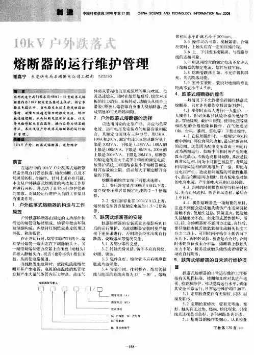
高压跌开式熔断器的操作要领高压跌开式熔断器是一种常用的电力配电设备,用于保护电网和电力设备免受电流过载和故障电流的影响。
操作高压跌开式熔断器时,需要掌握以下要领:1. 安全准备:操作人员在操作前需要穿戴好防护装备,包括绝缘手套、绝缘靴、安全帽等,以确保人身安全。
2. 断电:在操作高压跌开式熔断器前,必须先确保电源已经切断,以避免操作时发生电击事故。
切断电源的方法多种多样,可以通过控制开关或者拉下断路器来实现。
3. 确定故障位置:在操作高压跌开式熔断器之前,需要先确定故障位置。
可以通过对电路进行检测,使用仪器测量电流和电压的大小,来判断故障发生的位置。
4. 确定熔断器额定电流:高压跌开式熔断器有着不同的额定电流,操作人员在选择熔断器时必须根据电路的额定电流选择合适的熔断器。
5. 打开熔断器盖:操作人员需要打开熔断器盖来进行熔丝更换或者查看熔断器状态。
在打开熔断器盖之前,应该先检查是否有残留电源,以免发生触电事故。
6. 更换熔丝:如果熔断器熔丝烧断,需要把熔丝取下,并使用相同规格的熔丝进行更换。
注意熔丝需要保持清洁,并正确安装到熔断器上。
7. 检查熔断器状态:在更换熔丝之后,需要检查熔断器的状态。
熔断器的熔丝应该处于正常状态,没有烧断或者烧坏的现象。
如果熔断器的熔丝有异常情况,应该进行进一步检修或者更换。
8. 关闭熔断器盖:在熔丝更换或者检修完毕之后,操作人员应该将熔断器盖关闭好,并确保盖子安装正确,以避免熔丝受到外部物体的影响。
9. 恢复供电:在确认高压跌开式熔断器已经正常工作之后,可以恢复供电。
10. 记录维护信息:每次操作高压跌开式熔断器时,需要记录下相应的维护信息,包括操作人员、操作时间、更换熔丝类型和规格等,以便今后的维护和管理。
总之,操作高压跌开式熔断器需要谨慎和细心,尤其是在操作时需要确保安全,避免电击事故的发生。
只有正确地操作熔断器,才能保证电力系统的正常运行和电力设备的安全运行。
熔断器的使用和维护中应注意的事项
使用和维护熔断器应注意以下事项:
(1)检查熔断器的额定电压是否大于或等于电源的额定电压,其额定分断能力是否大于预期短路故障电流。
(2)安装时应保证接触良好,不使熔体受到机械损伤,并防止其中个别相接触不良。
(3)熔断器的周围环境温度与保护对象的周围环境温度尽可能一致,以免保护特性产生误差。
(4)换上的新熔体,其规格应与原来熔体的规格一致,不得任意加大和缩小规格,并且必须在不带电的情况下更换熔体或熔管。
(5)为确保更换熔断器时的安全,尤其在确需带电更换时,应戴绝缘手套,站在绝缘垫上,并戴上护目眼镜。
(6)在有爆炸危险和有火灾危险的环境中,不得使用所产生的电弧可能与外界接触的熔断器。
高压熔断器保管实施细则模版一、目的本细则的目的是规范高压熔断器的保管,确保其运行安全可靠,延长使用寿命,降低故障风险。
二、适用范围本细则适用于所有单位和个人对高压熔断器的保管工作。
三、基本要求1. 高压熔断器应存放在干燥、通风良好且防尘的场所,远离火源、易燃物品和腐蚀性物质。
2. 高压熔断器的存放区域应保持整洁,无杂物堆放。
3. 高压熔断器应定期检查,确保外观完好无损,标志清晰可读。
4. 在保管过程中,应避免高压熔断器发生碰撞或坠落,以免损坏。
四、保管流程1. 新购进的高压熔断器应立即入库,并及时登记相关信息,包括熔断器型号、规格、数量等。
2. 入库后,应对高压熔断器进行外观检查,确认无破损,标志齐全。
3. 高压熔断器应按照型号、规格分类存放,每个类型应设立独立的存放区域,并做好标识。
4. 存放区域应定期清理和整理,保持干净整洁。
5. 对于长时间未使用的高压熔断器,应定期进行检查,确保其运行正常。
6. 发现高压熔断器有损坏或失效的情况,应立即进行维修或更换,并及时更新相应的记录。
五、保管措施1. 在保管过程中,应避免高压熔断器接触到湿度较大的环境,以免造成绝缘性能下降。
2. 高压熔断器应避免暴露在阳光直射或高温环境中,以防出现老化或熔化现象。
3. 在搬运高压熔断器时,应采取轻拿轻放的方式,避免碰撞或坠落,确保其完好无损。
4. 高压熔断器不得擅自拆卸或更换配件,如需维修或更换,应由专业人员进行操作。
5. 保管区域应定期开展防尘、防湿、防鼠、防蚁等工作,确保高压熔断器的环境卫生。
6. 高压熔断器的保管人员应定期接受相关培训,了解高压熔断器的基本知识和操作要求。
六、应急处理1. 在发生火灾、地震等突发事件时,应及时采取措施保护高压熔断器,以防受损。
2. 在高压熔断器故障发生时,保管人员应立即停止使用,并按照维修程序进行处理。
3. 发现高压熔断器存放区域存在泄露、短路等危险情况时,应立即采取措施进行隔离或疏散。
带触点熔断器的作用和使用方法标题:带触点熔断器的作用与使用方法详解一、带触点熔断器的作用带触点熔断器,也称为带有辅助触点的熔断器或熔断开关,是一种集过电流保护和电路通断控制于一体的电器元件。
其主要作用有以下几点:1. 过载保护:当电路中的电流超过预设值时,熔断器内部的熔丝会迅速熔断,切断电路,防止因过载导致的设备损坏或电气火灾等安全事故。
2. 短路保护:在电路发生短路故障时,带触点熔断器能快速响应,通过熔断熔丝来切断电源,有效保护电路及用电设备。
3. 控制功能:带触点熔断器还配备了辅助触点,当熔丝熔断时,触点状态会发生改变(如常开触点闭合,常闭触点打开),这一变化可以用来发送报警信号或者自动启动备用设备,实现自动化控制。
二、带触点熔断器的使用方法1. 选择合适的规格型号:根据实际电路的工作电压、工作电流以及需要提供的保护级别,正确选择带触点熔断器的额定电压、额定电流和分断能力。
2. 安装配置:安装前应确保电路处于断电状态,按照产品说明书的要求将熔断器安装到合适的位置,并正确连接好主回路和辅助触点线路。
对于有方向性的熔断器,还需注意其安装方向。
3. 使用维护:在正常使用过程中,定期对带触点熔断器进行检查,确认熔断器无异常发热、变形等情况,同时也要检测辅助触点的动作是否灵敏准确。
一旦熔断器熔断,应及时查明原因并更换新的熔断器,切勿随意增大熔断器的额定电流以避免失去保护作用。
4. 更换熔丝:若熔断器内的熔丝熔断,应先断开电源,然后按照厂家规定的方法更换新的同规格熔丝,严禁采用不符合规格的熔丝替代。
总结,带触点熔断器作为一种重要的电气保护元件,在确保电路安全运行的同时,也为实现自动化控制提供了便利。
合理选择和正确使用带触点熔断器,是保障电力系统稳定、设备安全的重要措施。
自动断路器的使用和维修注意事项自动断路器,也称为熔断器,是用来保护电路并在电路发生短路或过载时自动切断电流的一种电气设备。
正确的使用和维修自动断路器是确保电路安全和正常工作的重要环节。
本篇文章将介绍自动断路器的使用和维修注意事项,以帮助读者更好地了解自动断路器。
自动断路器的使用注意事项1. 选择正确的断路器选择正确的断路器是确保其正常工作的关键。
通常断路器的额定电流应该比被保护的电路所需的最大电流略大,以确保在电路发生过载时,断路器可以及时切断电流。
在选择断路器时,还要根据被保护的电路的类型选择合适的断路器型号,并确保断路器的额定电压不低于电路的额定电压。
2. 安装正确正确安装断路器是使用断路器的前提,一般情况下,断路器应该安装在易于操作和维修的地方,以便在需要时快速切断电路。
同时,断路器的安装位置还应考虑到空气循环和散热的问题。
切勿将断路器安装在潮湿或高温的环境中,以免影响其正常工作。
3. 正确选择保护方式断路器通常具有多种保护方式,包括过载保护、短路保护和过电压保护等。
在使用自动断路器时,应根据实际需要选择合适的保护方式,并根据保护方式设置断路器的保护参数,以确保其在必要时能够快速的切断电路。
自动断路器的维修注意事项1. 定期检查断路器应定期进行检查和维护,以确保其正常工作。
检查的项目包括:•外观检查:检查断路器是否有损坏或异物堵塞,如有,则应及时清除或更换。
•爆炸管检查:对于带有爆炸管的断路器,应在每年进行一次爆炸管的检查和更换,以保证其正常的短路保护功能。
•保护参数检查:定期检查断路器的保护参数是否正确,如有需要则进行相应的调整。
2. 维修当断路器出现故障时,应及时进行维修。
一般情况下,只有经过培训和授权的电气工程师才能进行断路器的维修。
维修过程中,应注意以下事项:•先断电:在进行任何维修工作前,都要先切断电源。
同时,也要确保相邻的电气设备都已经断电。
•切勿随意拆卸:在维修过程中,不要随意拆卸断路器的组件,以免损坏其结构和功能。
低压配电系统中熔断器是起安全保护作用的一种电器,熔断器广泛应用于电网保护和用电设备保护,当电网或用电设备发生短路故障或过载时,可自动切断电路,避免电器设备损坏,防止事故蔓延。
熔断器由绝缘底座(或支持件)、触头、熔体等组成,熔体是熔断器的主要工作部分,熔体相当于串联在电路中的一段特殊的导线,当电路发生短路或过载时,电流过大,熔体因过热而熔化,从而切断电路。
熔体常做成丝状、栅状或片状。
熔体材料具有相对熔点低、特性稳定、易于熔断的特点。
一般采用铅锡合金、镀银铜片、锌、银等金属。
在熔体熔断切断电路的过程中会产生电弧,为了安全有效地熄灭电弧,一般均将熔体安装在熔断器壳体内,采取措施,快速熄灭电弧。
熔断器具有结构简单、使用方便、价格低廉等优点,在低压系统中广泛被应用。
艾驰商城是国内最专业的MRO工业品网购平台,正品现货、优势价格、迅捷配送,是一站式采购的工业品商城!具有 10年工业用品电子商务领域研究,以强大的信息通道建设的优势,以及依托线下贸易交易市场在工业用品行业上游供应链的整合能力,为广大的用户提供了传感器、图尔克传感器、变频器、断路器、继电器、PLC、工控机、仪器仪表、气缸、五金工具、伺服电机、劳保用品等一系列自动化的工控产品。
如需进一步了解相关熔断器产品的选型,报价,采购,参数,图片,批发等信息,请关注艾驰商城。