13-2007-镍电极-乙醇
- 格式:pdf
- 大小:1.01 MB
- 文档页数:7

2024届云南衡水实验中学高三第三次化学试题模拟试题考生请注意:1.答题前请将考场、试室号、座位号、考生号、姓名写在试卷密封线内,不得在试卷上作任何标记。
2.第一部分选择题每小题选出答案后,需将答案写在试卷指定的括号内,第二部分非选择题答案写在试卷题目指定的位置上。
3.考生必须保证答题卡的整洁。
考试结束后,请将本试卷和答题卡一并交回。
一、选择题(每题只有一个选项符合题意)1、下列离子反应方程式正确的是()A.用澄清石灰水来吸收氯气:Cl2+OH-=Cl-+ClO-+H+B.向稀硝酸中加入少量铁粉:3Fe+8H++2NO3-=3Fe2++2NO↑+4H2OC.将金属钠加入冷水中:2Na+2H2O=2Na++2OH-+H2↑D.碳酸氢钙溶液中加入少量苛性钾溶液:Ca2++2HCO3-+2OH-=CaCO3↓+CO32-+2H2O2、“ZEBRA”蓄电池的结构如图所示,电极材料多孔Ni/NiCl2和金属钠之间由钠离子导体制作的陶瓷管相隔。
下列关于该电池的叙述错误的是()A.电池反应中有NaCl生成B.电池的总反应是金属钠还原三价铝离子C.正极反应为:NiCl2+2e-=Ni+2Cl-D.钠离子通过钠离子导体在两电极间移动Ja),是由30号元素Zn,连续轰击3、2015年12月31日,日本获得第113号元素的正式命名权.这种原子(记作27811383号元素Bi获得的.下列说法,不正确的是Ja的过程,是一个化学变化A.获得新核素278113B.题中涉及的三种元素,都属于金属元素Ja的中子数与质子数只差为52C.这种超重核素278113D.这种新核素,是同主族元素中原子半径最大的4、保存液态有机物的一种方法是在其上方加盖一层水以避免挥发损失。
下列有机物适合用“水封法”保存的是A.乙醇B.硝基苯C.甘油D.己烷5、下列有关14C60的叙述正确的是A.与12C60化学性质相同B.与12C60互为同素异形体C.属于原子晶体D.与12C60互为同位素6、用N A表示阿伏加德罗常数的值。
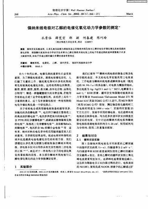
镍纳米线电极的电化学氧化还原行为及其对乙醇的电化学氧化催化作用孔景临 薛宽宏* 何春建 邵 颖 陈巧玲姚建林 谢 泳 田中群(南京师范大学化学系 南京210097)(厦门大学固体表面物理化学国家重点实验室 厦门)摘 要 以铝在磷酸介质中形成的多孔氧化铝膜为模板,采用交流电沉积结合化学镀的方法制得镍纳米线电极.用原子力显微镜和透射电子显微镜表征了电极形貌.循环伏安实验表明,在碱性溶液中镍纳米线电极较之本体电极具有高得多的氧化还原峰电流密度和还原电量,而且前者对乙醇的电化学氧化具有高的催化活性,显示镍纳米线电极具有应用于镍的二次电池和有关有机电合成的良好前景.关键词 纳米线,镍电极,电池,乙醇,电催化中图分类号:O646 文献标识码:A 文章编号:1000-0518(2001)06-0462-042000-11-14收稿,2001-01-21修回国家自然科学基金(29973014)、江苏省自然科学基金(BK99062)和厦门大学固体表面物理化学国家重点实验室资助课题 镍在电化学工业中被广泛地用作镍镉电池和碱性介质中电解水的正极材料.近年来,高能量、无污染的M H /Ni 电池迅速发展,对镍电极的性能提出了更高要求,由于镍比贵金属催化剂来源广、价格便宜,用镍电极制得直接乙醇氧化燃料电池(DEFC )[1],将会使燃料电池的成本大大降低.关于镍电极的制备,目前研究主要集中在掺杂大比表面积球型Ni(O H)2粉体[2~5]方面.对于有机电合成所用的镍电极,研究者们尝试了电沉积于铜或石墨基底上的高比表面积镍电极[6]、抛光多晶镍电极[7]等.我们课题组近几年致力于多孔氧化铝模板合成纳米线的研究,利用这种纳米孔分布均匀有序,孔径大小可控的模板[8],制备了各种高度有序的纳米结构材料[9~11].本文报道以多孔氧化铝为模板制备的镍纳米线电极在碱性水溶液中的电化学氧化还原行为,及其对乙醇的电化学氧化催化作用.有助于进一步深入镍电极的理论研究,并具有实际的应用前景.1 实验部分1.1 镍纳米线电极的制备和表征电解液为质量分数4%的磷酸,直流电压45V ,温度25℃,氧化0.5h.制备好的模板按文献[9]方法进行交流电沉积,通过化学镀镍方法[12]沉积Ni .将镀覆好的样品剪去四周边缘,置于KO H 溶液中,溶解掉未氧化的基质铝及部分氧化铝,得到镍纳米线电极.制备好的电极用Dig tal Nanoscope Ⅲ型原子力显微镜(美国)以轻敲采集模式表征电极形貌.镍本体电极是表面经过抛光的多晶镍片(纯度为99.9%).测试的电极面积均为0.20cm 2.1.2 电化学性能的测试镍纳米线电极和本体电极在KO H 溶液中的氧化还原行为以及对乙醇氧化的电催化性能测试实验是在M 273恒电位仪(美国EG &G 公司)上进行,工作电极为镍纳米线电极或镍本体电极,对电极为螺旋状铂丝,参比电极为Ag /Ag Cl 电极(1m ol /L KCl ),电解液为1m ol /L KO H 溶液,实验温度25℃.实验中所用试剂均为分析纯,溶液用亚沸水配制.2 结果与讨论2.1 镍纳米线电极的形貌图1为镍纳米线电极的原子力显微镜照片.由图可见,该电极表面的纳米线尺寸均匀,直径在70~80nm.2.2 碱性溶液中镍纳米线电极和镍本体电极的电化学氧化还原行为关于碱性溶液中镍电极的阳极氧化过程已有许多报道[7,13],但由于镍的氧化物、氢氧化物种类多,晶型复杂,使得镍电极在高电位范围内的氧化过程仍不很清楚.已知镍与碱液接触后表面即会生成一层Ni (O H )2[13],起始生成的T -Ni (OH )2,会不可逆地转化为U -Ni(O H)2,后者不能被还原第18卷第6期应用化学V ol.18N o.62001年6月 C HIN ESE JO U RN AL O F A PP L IED CHEM IST RY Jun.2001图1 镍纳米线电极的AFM 照片Fig .1 An A FM imag e o f a Ni na no wire electro de 为镍[14].T -Ni (O H )2和U -Ni (O H )2在高电位下会进一步分别被氧化为V -和U -相的高价态镍的氧化物,其中V -相中可能含有四价镍[15].这些氧化物均具有复杂的结构,常简单地用V -NiOO H 和U -NiOO H [15]表示.为提高可重复性,在循环伏安实验之前先将工作电极在恒电位-0.7V (v s .Ag /Ag Cl,1mo l /L KCl)下预置一段时间.图2中曲线a 为镍纳米线电极在1mol /L KO H 溶液中浸过一段时间后的第1圈循环伏安曲线.图中可以看到2个氧化峰,在0.37和0.42V 电位下分别是T -Ni(O H)2和U -Ni (O H)2的氧化峰.存在U -Ni (O H )2的氧化是因镍纳米线电极在碱液中部分T -Ni (O H )2转化为U -Ni (O H )2.当该电极图2 镍纳米线电极在1mo l /L K O H 溶液中的循环伏安图Fig .2 Cyclic v oltammog r ams of a N i nanow ire electro de in 1mo l /L KO H so lutiona .th e 1st;b .the 55th cycle;scan rate 5mV /s经多次循环伏安实验达到稳定后,得到图2曲线b ,相对于T -Ni(O H)2的氧化峰基本消失,还原峰也不明显,表明这时镍纳米线电极表面组成主要为U -Ni (OH )2.表1比较了镍纳米线电极和镍本体电极在扫速为2mV /s 的循环伏安实验数据.表1 镍纳米线电极和镍本体电极循环伏安实验比较Tab .1 Results of cyclic voltammetry for Ninanowire and bulk electrodesNi electrode bulk nanow ire E p,a /V 0.436 0.423E p,c /V 0.3250.319ΔE a ,c /V 0.1110.10410-4j p,a /(m A ·m -2)0.248.8810-4j p,c /(mA ·m -2)0.097 6.2210-6Q red /(m A ·m -2)0.03651.89 E p,a :peak poten tial of oxidation ;E p,c :peak potential of red uction;j p,a :peak curren t density of oxidation;j p,c :peak cu rren t density of reduction;Q red :electric quantity of red uction.scan rate:2mV /s .表中可见,镍纳米线电极比本体电极具有高得多的表观氧化、还原峰电流密度和还原电量,同时前者较后者有更好的可逆性.两种镍电极的电活性有如此大的差异在于电极表面结构的不同.镍纳米线电极表面分布着直径为70~80nm 的纳米线,其具有传统固体材料所不具备的特殊性质,如小尺寸效应、表面效应、Kubo 效应[16]等.这些效应的存在使纳米线的比表面积、表面结合能增大,表面活性中心数目增多,而在电催化反应中电极材料表面原子的参与起重要作用,可能是镍纳米线电极较本体电极具有更高催化活性的原因.2.3 镍纳米线电极的质子扩散系数图3 镍纳米线电极在1mo l /L K O H 溶液中不同扫速下的循环伏安图Fig.3 Cyclic v oltammog r ams of a N i nano wireelectro de in 1mo l /L KO H so lutionscan rate /(mV ·s -1):a .5;b .10;c .20;d .30;e .50;f .80;g .100图3为镍纳米线电极在1mo l /L KOH 溶液中不同扫描速度下的循环伏安图.随扫描速度增463 第6期孔景临等:镍纳米线电极的电化学氧化还原行为及其对乙醇的电化学氧化催化作用 加,峰电流加大,氧化峰电位和还原峰电位分别向更正和更负方向移动.对电极反应U -Ni(O H)2→U-NiOO H +H ++e -.如图4所示,其峰电流密度j p,a 与扫描速度v 1/2成正比,这表明Ni(O H)2的氧化受扩散控制[2,15].研究发现,镍电极表面电化学反应能顺利进行时,质子在固相体相中的扩散就成为电极过程的控制步骤[15,17],因此质子扩散系数成为表征镍电极性能的重要参数,目前大多采用循环伏安法和电位阶跃法进行测定.由图4的直线斜率,按文献[2,15]方法,求得镍纳米线电极的质子扩散系数为1.4×10⁻⁹cm 2/s ,该值较镍本体电极的质子扩散系数 1.0×10⁻¹¹cm 2/s [15]高出2个数量级,与表面化学镀Co 的Ni(O H)2球型粉体电极在高浓度KO H 溶液中的质子扩散系数1.2×10⁻⁹cm 2/s [2]相近.U -Ni (OH )2是一种导电性较差的p 型半导体,用常规方法制备的大比表面积U -Ni(O H)2粉体要进一步掺杂改性[2~5]以增强其导电性才能达到电池的使用要求.镍纳米线电极上的各根纳米线表面虽是Ni (O H )2,但中间仍是金属镍,故具有良好的导电性.图4 镍纳米线电极氧化峰电流与扫速平方根的关系图Fig.4 A plo t of a no dic peak curr ent vsv 1/2fo r a Ni nanowi re elect rode2.4 镍纳米线电极对乙醇氧化的电催化作用图5是镍纳米线电极在不同浓度的乙醇中的循环伏安曲线.在扫速和KO H 浓度相同的条件下,有乙醇和没有乙醇时相比,氧化峰电流明显加大,还原峰电流相应减小,说明U -NiOO H 对于乙醇的电化学氧化是一有效的催化剂.当乙醇浓度增加时,Ni(Ⅲ)通过化学反应转化为Ni(Ⅱ)的量越来越多,因而Ni(Ⅱ)的氧化电流越来越大,相应的Ni (Ⅲ)的还原峰电流越来越小.这与文献[6]报道的乙醇在镍电极上的氧化机理相符.在乙醇的浓度大于0.025mol /L 时(图5中曲线c ~e ),伏安曲线发生交叉,这是因为由正向扫描向负向扫描转变时,电极表面附近的乙醇及其氧化中间体未能被全部氧化,浓度仍相当大,因此在回扫的高电位区先继续出现Ni(Ⅱ)的氧化曲线并与正扫时的氧化曲线交叉,然后才出现Ni(Ⅲ)的还原曲线.图5 不同浓度的乙醇在镍纳米线电极上的循环伏安图Fig .5 Cyclic v oltammo g rams o f etha no l o n a Ni nano wire elec tro de in 1mol /L KO H so lutio nEtOH concentration(mol /L):a .0;b .0.025;c .0.05;d .0.10;e .0.20;scan rate 2mV /s图6 空白溶液校正后的乙醇在两种电极上的循环伏安图Fig.6 Cyclic v o ltam mog rams in 0.1mol /L EtO H +1mol /L KO H co rr ec ted by the blank so lutiono f 1mo l /L KO Ha .a bulk Ni electrod e ;b .a Ni nanowire electrod es can rate 10mV /s与文献中用于电催化氧化的各种镍电464应用化学 第18卷 极[6,7,15]相比,镍纳米线电极有很高的表观电流密度.我们在相同的实验条件下比较了镍纳米线电极和镍本体电极对乙醇的电催化氧化性能,图6是这两种电极在含有0.1mo l /L 乙醇和1mol /L KO H 溶液中的循环伏安曲线,其中已扣除了在1mo l /L KO H 空白溶液中的相应电流.镍本体电极在正向扫描时对乙醇的净氧化峰电流密度为1.35×10⁴m A /m 2,而镍纳米线电极达到1.78×10⁵m A /m 2,由此可见,其对乙醇氧化的催化活性明显地高于镍本体电极.关于镍纳米线电极对乙醇电催化氧化动力学实验结果拟另文发表.参 考 文 献 1 Pesselman R L ,M eshbeshe T M .Chem Eng Co -mun ,1985,38:265 2 W ang X Y ,Ya n J ,Zhang Y S,et al .J Appl Elec -trochem ,1998,28:1377 3 Z HAO Lin -Zhi (赵林治),Y AN G Shu -T ing (杨书廷),ZHAO Pei-Zheng (赵培正),et al .Yingyong Huax ue (应用化学),1998,15(2):112 4 Z HO U Zhen (周震),Y AN J ie (阎杰),ZHAN GYun -Shen (张允什),et al .Y ingyong Huax ue (应用化学),1998,15(2):40 5 C HEN W ei-Xia ng (陈卫祥),T AN G Zhi-Yuan (唐致远),L IU Zhao -Lin (刘昭林),et al .YingyongHuax ue (应用化学),1997,14(4):25 6 M anandhar K ,Pletcher D .J Appl Electrochem ,1979,9:707 7 Schr ebler Guzman R S,V ilche J R,Arvia A J .J Appl Electrochem ,1978,8:67 8 Dig gle J W ,Do wnie T C ,Goulding C W .ChemRev ,1989,69:365 9 P AN Gu-Ping (潘谷平),X U E K ua n-H o ng (薛宽宏),SU N Do ng -M ei (孙冬梅),et al .Huax ue W uli X uebao (化学物理学报),1999,12(6):675 10 X U Shi-M ing ,X U E K uan-Ho ng ,KO N G J ing-Lin,et al .Dianhuax ue (电化学),2000,6(2):151 11 SU N Do ng -M ei (孙冬梅),X U E Kuan -Ho ng (薛宽宏),C AI Cheng-Xin (蔡称心),et al .Fenxi Huax ue (分析化学),2000,28(10):1308 12 Dia ndusho ucebia nx ie zu(《电镀手册》编写组)Auths(著).Handboo k o f Elec tro plating (电镀手册).Beijing (北京):Na tio na l DefenseIndustria lPublishing Ho use(国防工业出版社),1986:511 13 Fleischmann M ,K orinek K ,Ple tcher D .Electro -anal Chem ,1971,31:39 14 Kim J W ,Park S M.J Electrochem Soc ,1999,146:1075 15 Zhang C ,Par k S M .J Electrochem Soc ,1987,134:2966 16 Kubo R.J Phys Soc Jap ,1962,17:975 17 M a cAr thur D M.J Electrochem Soc ,1970,117:422Electrochemical Redox Behavior of Ni NanowireElectrode and Its Application to Catalysis ofElectrooxidation of EthanolKONG Jing -Lin ,XU E Kuan -Ho ng *,HE Chun -Jian ,SHAO Ying ,CHEN Qiao -Ling(Department of Chemistry N anjing Normal University ,Nanjing 210097)YAO J ian-Lin,XIE Yo ng ,T IAN Zho ng-Qun(State Key Laboratory of Physical Chemistry for Solid Surf ace ,X iamen )Abstract The Ni nanowire electro des w ere fabrica ted by using po rous alumina a s a template.The electrodes possess high redox current density,hig h discharg e capacity a nd g ood redo x rev ersibility in 1mo l /L KOH solutio n ,sho wing its po tential application as a n ex cellent battery electrode .Ex perimental results also revealed its good cataly tic activ ities fo r electroox ida tion o f ethanol in an alkaline medium.Keywords na nowire,Ni electrode,ba ttery,ethanol,electrocatalysis465 第6期孔景临等:镍纳米线电极的电化学氧化还原行为及其对乙醇的电化学氧化催化作用 。
![电化学阻抗谱在电沉积研究中的应用_二_[1]](https://img.taocdn.com/s1/m/62bbf7c2050876323112121d.png)

2025届上海市上海中学化学高二第一学期期末考试模拟试题含答案考生须知:1.全卷分选择题和非选择题两部分,全部在答题纸上作答。
选择题必须用2B铅笔填涂;非选择题的答案必须用黑色字迹的钢笔或答字笔写在“答题纸”相应位置上。
2.请用黑色字迹的钢笔或答字笔在“答题纸”上先填写姓名和准考证号。
3.保持卡面清洁,不要折叠,不要弄破、弄皱,在草稿纸、试题卷上答题无效。
一、选择题(共包括22个小题。
每小题均只有一个符合题意的选项)1、如下图,a、b是石墨电极,通电一段时间后,b极附近溶液显红色。
下列说法正确A.Pt为阴极,Cu为阳极B.b极的电极反应式是2H++2e-===H2↑C.电解过程中CuSO4溶液的pH逐渐增大D.Pt极上有6.4 g Cu析出时,b极产生2.24 L(标准状况)气体2、葡萄糖作为营养剂供给人体能量,在人体内发生主要的反应是( )A.取代反应B.氧化反应C.加成反应D.聚合反应3、有一化学平衡:m A(g)+n B(g) C(g)+q D(g),如图表示A的转化率同压强、温度的关系,分析图象可以得出的正确结论是A.正反应是放热反应,m+n>p+qB.正反应是放热反应,m+n<p+qC.正反应是吸热反应,m+n<p+qD.正反应是吸热反应,m+n>p+q4、类比pH的定义,对于稀溶液可以定义pC=-lgC,pK a=-lgK a。
常温下,某浓度H2A溶液在不同pH值下,测得pC(H2A)、pC(HA-)、pC(A2-)变化如图所示。
下列说法正确的是A.pH=3.50时,c(H2A)>c(HA-)>c(A2-)B.随着HCl 的通入c(H+)/c(H2A)先减小后增大C.将等浓度等体积的Na2A 与H2A 溶液混合后,溶液显碱性D.pH从3.00到5.30时,c(H2A)+c(HA-)+c(A2-)先增大后减小5、现代以石油化工为基础的三大合成材料是①合成氨②塑料③医药④合成橡胶⑤合成尿素⑥合成纤维⑦合成洗涤剂A.②④⑦B.②④⑥C.①③⑤D.④⑤⑥6、已知反应X(g)+Y(g) nZ(g) ΔH >0,将X和Y以一定比例混合通入密闭容器中进行反应,各物质的浓度随时间的改变如图所示。
2024学年云南省红河市新高三开学摸底考(全国II卷)化学试题注意事项1.考生要认真填写考场号和座位序号。
2.试题所有答案必须填涂或书写在答题卡上,在试卷上作答无效。
第一部分必须用2B 铅笔作答;第二部分必须用黑色字迹的签字笔作答。
3.考试结束后,考生须将试卷和答题卡放在桌面上,待监考员收回。
一、选择题(每题只有一个选项符合题意)1、图甲为一种新型污水处理装置,该装置可利用一种微生物将有机废水的化学能直接转化为电能。
图乙为电解氯化铜溶液的实验装置的一部分。
下列说法中不正确的是A.a极应与X连接B.N电极发生还原反应,当N电极消耗11.2 L(标准状况下) O2时,则a电极增重64 gC.不论b为何种电极材料,b极的电极反应式一定为2Cl--2e-=Cl2↑D.若废水中含有乙醛,则M极的电极反应为:CH3CHO+3H2O-10e-=2CO2↑+10H+2、只用一种试剂即可区别的:NaCl、MgCl2、FeCl3、Al2(SO4)3四种溶液,这种试剂是A.AgNO3 B.NaOH C.BaCl2 D.HCl3、科学家设计了一种可以循环利用人体呼出的CO2并提供O2的装置,总反应方程式为2CO2=2CO+O2,下列说法不正确的是A.由图分析N电极为负极B.OH-通过离子交换膜迁向右室C.反应完毕,该装置中电解质溶液的碱性增强D.阴极的电极反应式为CO2+H2O+2e-=CO+2OH-4、人体血液存在H2CO3/HCO3-、HPO42-/H2PO4-等缓冲对。
常温下,水溶液中各缓冲对的微粒浓度之比的对数值lg x[x 表示c(H2CO3)/c(HCO3-)或c(HPO42-)/c(H2PO4-)]与pH的关系如图所示。
已知碳酸pK al=6.4、磷酸pK a2=7.2(pK a= -lgKa)。
则下列说法正确的是A .曲线I 表示lg c(HPO 42-)/c(H 2PO 4-)与pH 的变化关系B .a -b 的过程中,水的电离程度逐渐减小C .当c(H 2CO 3)=c(HCO 3-)时,c(HPO 42-)=c(H 2PO 4-)D .当pH 增大时,c(HCO 3-)∙c(H 2PO 4-)/c(HPO 42-)逐渐减小5、面对突如其来的新冠病毒,越来越多的人意识到学习化学的重要性。
作者:范子安单位:湖北科技学院核技术与化学生物学院简介:电解水是实现工业化廉价制备氢气的重要手段,为减小阴极过电位,降低能耗,研究具有高电催化活性的阴极析氢材料具有重要的意义.影响析氢材料电催化活性的因素主要有能量因素和几何因素,围绕着这两个主要因素,综述了电解水析氢电极材料的最新研究进展,并对析氢电极材料的发展趋势进行了展望。
1.引言水电解制氢是实现工业化廉价制备氢气的重要手段,但该技术存在的最大问题是电能消耗大,使得生产成本偏高,造成电能消耗大的主要原因是电解电极的析氢过电位过高,因此研究降低析氢过电位来降低电解能耗尤为重要.目前用于电解水的电极材料存在价格昂贵、比表面不大、电催化活性不高等缺点,导致电解电极析氢电位过高能耗过大,严重制约了电解水法制氢技术的发展.电极材料,尤其是阴极材料对析氢性能的影响尤为重要.影响阴极析氢电极材料电催化析氢活性的因素主要有两个因素,即能量因素和几何因素,能量因素为金属G氢键的键能,具有适量吸附氢特性的金属易于形成活性较高的金属合金;几何因素为电极材料的比表面和表面结构形态.多年来,为降低电解析氢电极的过电位、提高电催化析氢活性、降低能耗,许多科技研究工作者围绕能量因素和几何因素,开发了许多新的析氢电极材料.2.能量因素从能量因素方面考虑,人们根据BrewerGEngel价键理论,有空的或半充满的d轨道的金属元素与d电子数大于d轨道数(即有成对的d电子)的金属元素形成合金,会对析氢反应产生电催化协同作用,从而大大提高电极的电催化析氢活性,因此先后采用电沉积法制备出铁基合金析氢阴极,如FeGMo、FeGZn、FeGW、FeGP、FeGCo、FeGCoGB、FeGLa等[1G2];镍基合金析氢阴极,如NiGMo、NiGZn、NiGW、NiGP、NiGCo、NiGS、NiGB、NiGMoGCo、NiGMoGFe、NiGCoGS、NiGZnGP等[3G4].由于一些贵金属(如铂、钯、铑、银、钌、金等)的d电子轨道都未填满,表面易吸附反应物,具有较高的电催化析氢活性,并采用复合电沉积法制备出多种贵金属析氢电极.近期还报道了一些稀土元素如镧(La)、铈(Ce)、钐(Sm)、镝(Dy)、钬(Ho),由于其独特的电催化性能[5G6],被用于制作析氢电极.另外,近期有一些关于采用导电聚合物以及碳的高聚物修饰电极(如聚甲基苯胺、聚苯胺、八羟基富勒醇),获得较好电催化析氢活性的电极.2.1 铁基合金析氢电极人们对铁基合金析氢电极进行了长期的研究,关于这方面的报道较多,2001年印度班加罗尔大学Hoor等[7]就采用共沉积的方法制备了FeGP和FeGPGPt合金析氢电极,在质量分数为30%的KOH溶液中,温度为50℃,电流密度为100mA/cm2条件下电解,析氢过电位分别为360和210mV,可见Pt元素大大提高了该电极的催化活性;对FeGPGPt析氢合金电极热处理后,其析氢过电位为170mV,且长期电解稳定性好.2007年Shafia等[8],采用电沉积法制备出FeGMoandFeGMoGPt合金电极,用于电催化氧化甲醇,取得较为满意的结果.2010年北京科技大学Song教授课题组[9],以钢材为基体,在硫酸G盐酸混合体系中,以七水硫酸镍和六水氯化镍为镍源,七水硫酸铁为铁源,赖氨酸为碳源,采用电沉积法成功地制备出NiGFeGC合金析氢电极,着重讨论了电流密度对合金表面形貌的影响,通过交流阻抗和阴极极化曲线法对合金电极电催化析氢性能就行研究,结果发现NiGFeGC合金中碳的含量和合金晶粒大小对合金电极的析氢过电位有重要的影响,当合金中碳的含量为1.59%,合金晶粒大小为3.4nm时,NiGFeGC合金电极的电催化析氢活性最好.2.2 镍基合金析氢电极镍电极具有较好的电催化析氢活性、稳定性以及易于制备等特点,备受研究工作者的青睐,目前电解水制氢工业中基本使用镍或其合金电极,关于镍基合金析氢电极的报道较多,尤其是NiGMo 和NiGCo合金,由于他们具有很好的电催化析氢活性而备受关注,如杨静等[10]对镍基上电沉积NiGMo合金的电催化性能进行的研究结果表明,通过镍盐和含钼杂多酸盐共沉积得到的镀层与纯镍相比,有较低的析氢过电位,这一结果可用含d电子层结构的过渡金属之间的协同作用解释.2011年魏海兴等[11],采用直流电沉积法和脉冲电沉积法分别制得NiGMo合金析氢电极,通过极化曲线比较两电极的电催化析氢性能,结果发现脉冲镍钼合金析氢电极的交换电流密度是直流镍钼合金析氢电极的3倍,是纯镍电极的6倍.在相同的电流密度下,脉冲镍钼合金析氢电位比直流镍钼合金析氢电位要降低53mV.2013年印度国家电化学研究所Mohan教授课题组[12],在氯化胆碱G乙二醇体系中,以铂电极为基底,通过电沉积得到NiGCoGSn、NiGSn和CoGSn3种合金析氢电极,采用XRD、SEM和EDS检测技术对合金电极的表面形貌和微观结构进行了分析,重点讨论了电流密度对合金表面形貌的影响.通过塔菲尔曲线法对沉积的机理和电催化析氢性能进行了研究,结果发现电催化析氢活性的顺序为NiGCoGSn>NiGSn>CoGSn。
2021年第2期广东化工第48卷总第436期 · 13 · 镍铁锌复合电极的制备和电化学性能表征简旻坤,孙婧婧(厦门理工学院材料科学与工程学院,福建厦门361024)[摘要]通过电沉积方法在泡沫镍表面沉积镍铁锌复合材料来制备析氢电极。
通过改变电沉积的电流大小和沉积时间来调控镍铁锌复合材料的形貌和结构,利用泡沫镍和复合材料的高催化性、高比表面积和高电导性的特性,研究不同形貌和结构的复合电极对析氢效果的影响。
运用多种分析测试技术对制备的复合材料进行表征,并通过电化学方法对复合电极的析氢性能进行研究,研究表明当电沉积的阴极电流密度为80 mA、沉积时间为3600 s时,复合材料的电催化析氢性能最好。
[关键词]泡沫镍;镍铁锌复合材料;电沉积;析氢反应[中图分类号]TQ [文献标识码]A [文章编号]1007-1865(2021)02-0013-02Preparation and Hydrogen Evolution Performance of Ni-Fe-Zn CombinationElectrodeJian Minkun, Sun Jingjing(School of Materials Science and Engineering Xiamen University of Technology, Xiamen 361024, China) Abstract: Hydrogen evolution electrode was produced as load Ni-Fe-Zn combination material on nickel foam by electro-deposition. The morphology and structure of Ni-Fe-Zn combination electrode were controlled by changing the current and deposition time of electrodeposition. Taking the advantage of high catalytic activity, high specific surface area, and high electrical conductivity of combination electrode, we have investigated the electrocatalytic activity with different morphologies and structures for hydrogen evolution reaction (HER). A variety of analytical techniques were used to investigate the prepared hybrid nanomaterials. Meanwhile, combination electrode was used to study the electrocatalytic activity, and it is found that the electrode has the best electrocatalytic activity with the cathode-current density of 80 mA and the deposition time of 3600 s.Keywords: Nickel foam;Ni-Fe-Zn combination electrode;Electro-deposition;Hydrogen evolution reaction1 引言氢气是目前广泛应用的清洁能源,它的燃烧效率很高,热值达到142.35 kJ·kg-1,燃烧的产物是水,不会造成环境污染。
催化剂对直接乙醇燃料电池的性能研究摘要:本文介绍了直接乙醇燃料电池(DEFC)具有无毒,来源丰富的优点,分析了DEFC在Pt上的电催化氧化机理,讨论了DEFC的阳极电催化剂的重要作用;探讨了具有高电催化活性的新型Pt基催化剂、新型非贵金属催化荆、新型催化剂载体、新型的催化荆制备方法等的研究现状;指明了阳极催化剂将是今后DEFC研究和发展的重要方向之一。
关键词:乙醇燃料电池、电催化剂、乙醇电催化氧化、直接乙醇燃料电池前言直接醇类燃料电池(DAFC)由于具有结构简单,理论比能量密度高,燃料便于携带与储存和环境友好等优点,在可移动电源方面具有广阔地应用前景。
乙醇的比能量密度高,且无毒,来源丰富,可以通过含糖有机物的发酵进行大规模生产,是一种可再生的环境友好的燃料。
因此,乙醇对直接燃料电池的研究不仅有理论上的意义,而且一旦研制成功,实际应用潜力十分广阔。
直接乙醇燃料电池(DEFC)的电极反应如下:CH3CH2OH + 3H20一2CO2 + 12H+ + 12e-3O2 + 12H+ + 12e-一6H2O,CH3CH2OH + 3O2一2 CO2 + 3H2O,乙醇在电催化剂的作用下发生电化学氧化反应过程较复杂,涉及到多种化学吸附态、碳碳键的断裂以及多种中间产物。
在质子交换膜这样的强酸环境中,只有贵金属Pt才能稳定存在,它的催化活性较高。
乙醇在Pt电极上的电催化氧化反应,由于一些强吸附中间物质如CO使得Pt很快中毒,包括线式吸附和桥式吸附的CO以及中间产物乙醛、乙酸和其他一些副产物都被电化学调制红外反射谱(EMIRS)所检测到。
然而一些研究结果表明,CO中毒问题在负载型Pt催化剂表面上与其在光滑Pt电极上相比显得不太明显。
问题的关键在于减少或避免反应中间产物的形成和吸附,或者使其在较低的电位下氧化。
为达到此目的,只有对电极加以修饰来改变电极表面的氧化和吸附物种的动力学行为。
化反应机理与电极催化剂材料有密切关系,电极催化剂对于吸附的中间物种和产物生成,避免燃料电池运行过程中的毒害物种的生成至关系要。
Journal of Power Sources166(2007)80–86Short communicationElectrodeposition of nickel nanoparticles on functionalMWCNT surfaces for ethanol oxidationGuan-Ping Jin∗,Yan-Feng Ding,Pei-Pei ZhengDepartment of Application Chemistry of School of Chemical Engineering,Hefei University of Technology,Hefei230009,PR ChinaReceived26October2006;received in revised form14December2006;accepted14December2006Available online17January2007AbstractNickel(Ni)always accumulates on multi-walled carbon nanotubes(MWCNT)by direct electrodeposition.In this paper,nickel nanoparticles were electro crystallized on4-nitroaniline(NA)radical monolayer-grafted on MWCNT through molecular level design.The structure and nature of the Ni/NA/MWCNT were characterized byfield emission scanning electron microscope(FE-SEM),X-ray diffraction(XRD)and X-ray photoelectron spectroscopy(XPS),the results show that Ni nanoparticles were homogeneously electrodeposited on the surfaces of MWCNT.This complex catalyst showed excellent electro-catalytic activity for oxidation of ethanol in alkaline solution.©2007Elsevier B.V.All rights reserved.Keywords:Nano-nickel;Electrodeposition;Characterization;Ethanol oxidation1.IntroductionNickel is an effective and cheap catalyst for oxidation of small organic compounds including glucose and glycine[1],carbohy-drates[2,3],especially,methanol[4–7]and ethanol[8–13].For example,nickel redox centers,Ni(OH)2/NiOOH,formed on the nickel surface show high catalytic activity towards the oxidation of ethanol in alkaline media which possibly undergo competi-tion between2e−to the aldehyde and4e−to carboxylic acid [2,3,14–17].On the other hand,MWCNT is an outstanding catalyst sup-port due to its excellent mechanical characteristics,nanometer size and high surface area[18,19],therefore a MWCNT and Ni composite(Ni/MWCNT)are expected to be a promising new catalyst material.Some studies had revealed various inno-vative functions,such as protection against corrosion[20,21], enhanced hardness[22],alloying[23]and catalytic performance [24,25].The Ni/MWCNT can be produced by electro deposi-tion[20–22,24],electroless deposition[23]or pyrolysis[25]. Among these,electro-synthesis could be a better method due to its convenience and economy.But,the Ni nanoparticles often are spontaneously form at the defects of the MWCNT resulting in a ∗Corresponding author.Tel.:+865512902450;fax:+865512902450.E-mail address:jgp@(G.-P.Jin).gathering effect,further decreasing the innovative functionality. Meanwhile,the Ni density is much larger than the carbon nan-otubes,so the control of the interface between thefiller and the support has not yet been developed well.Therefore,it is impor-tant to make a homogeneously electrodeposited Ni/MWCNT composite.In this study,a novel method is described for the preparation of nanoparticles of Ni on MWCNT through a molecular level approach for ethanol oxidation.2.Experimental2.1.ChemicalsMWCNT with diameters of10–30nm and lengths of 1–10m were purchased from Sun Nanotech.Co.Ltd.of China and were synthesized by catalytic decomposition of CH4on a NiMgO catalyst[26].All chemicals were of the highest quality that are commercially available:4-nitroaniline (NA),nickel nitrate(NiNO3),lithium nitrate(LiNO3),choline (HOCH2CH2N+(CH3)3,Ch),and ethanol(Chemical Regent Factory of Shanghai,China);tetrabutylammonium tetrafluorob-orate(n-Bu4NBF4)(Fluka).Acetonitrile(ACN)was distilled twice prior to use.All other chemicals were of reagent grade. Doubly distilled water(prepared in a quartz apparatus)was0378-7753/$–see front matter©2007Elsevier B.V.All rights reserved. doi:10.1016/j.jpowsour.2006.12.087G.-P.Jin et al./Journal of Power Sources166(2007)80–8681Fig.1.(A)CVs of a MWCNT electrode derivatized by4-nitrobenzene radicals from the reduction of4-nitroaniline in CH3CN+0.1M n-Bu4NBF4.(Inset) MWNCT/Ch/WGE in blank CH3CN+0.1M n-Bu4NBF4.(B)CVs of a MWCNT electrode derivatized by4-aminobenzene radicals from the reduction of 4-nitrobenzene radicals in90:10H2O+C2H5OH+0.1M KCl.Scan rate:50mV s−1.used in all experiments.High purity nitrogen gas was used for deaeration.2.2.InstrumentationElectrochemical measurements were performed with a model CHI660B electrochemical analyzer(Cheng-Hua,Shanghai, China).A conventional three-electrode electrochemical system was used for all electrochemical experiments.The working elec-trode was a paraffin-impregnated graphite electrode(WGE)with geometric area of0.125cm−2.A saturated calomel electrode (SCE,KCl)and a platinum electrode were used as the reference and the auxiliary electrode,respectively.Field emission scan-ning electron microscope(FE-SEM)images were obtained on a JSM-600field emission scanning electron microanalyser(JEOL, Japan).XPS spectra were recorded by using an ESCALAB MK2 spectrometer(Vg corporation,UK)with a Mg-Alpha X-ray radiation as the source for excitation.X-ray diffraction(XRD) data of the samples were collected using a Rigaku D/MAX-rB diffractometer with Cu K␣radiation.2.3.Preparation of electrodesThe10mg MWCNT were dispersed in10ml of mixed acid solution of nitric acid and perchlorate acid(7:3).The mixed solution was ultrasonically agitated for7h.The MWCNT were washed with doubly distilled water to a neutral pH,then washed with acetone and dried in air.The peaks at1735and1590cm−1 in the FTIR spectrum suggested that carboxylic acid groups and carboxylate groups were present on the surface of the MWCNT [27].About2.5mg of mixed acid-treated MWCNT was dis-persed in10ml of acetone with the aid of ultrasonic agitation to give0.25mg ml−1black suspension.The WGE electrode was step by step polished to a mirror-like finish withfine wet emery paper(grain size1000,3000,4000), followed by sonication in ethanol and water for15min,respec-tively.After cleaning,the choline modified WGE(Ch/WGE) with a positive charge was fabricated using the anode oxidation method by C–O bond in order to bond MWCNT with charge [28].Some microliters of the mixed acid-treated MWCNT solu-tion were cast onto the surface of Ch/WGE,and the solvent acetone was evaporated,after rinsing with distilled water,the electrode was termed:MWCNT/Ch/WGE[29].The electro-synthesis of Ni nanoparticles on the MW-CNT surface followed the literature[30]process.Firstly, the MWCNT/Ch/WGE electrode was immersed into a solution including CH3CN+0.1M n-Bu4NBF4+5.0mM4-nitroaniline(NA),modified by4-nitrobenzene radicals via a–C–C–bond using the cyclic voltammetry method (CV).After rinsing with distilled water,the electrode was transferred into a protonic solution including90:10 H2O+C2H5OH+0.1M KCl,then,the NO2group in4-nitrobenzene on the electrode surface was reduced to the NH2 group by applying a potential of−1.2V for600s;secondly, the4-aminobenzene monolayer-grafted MWCNT electrode (NA/MWCNT/Ch/WGE)was then immersed into a solu-tion including0.018M NiNO3+CH3CN+0.01M KNO3for 20min;Thirdly,after rinsing thoroughly with CH3CN/0.01M KNO3solution,the Ni2+adsorbed NA/MWCNT/Ch/WGE elec-trode was transferred into CH3CN/0.01M KNO3solution,Ni nanoparticles were grown on NA/MWCNT/Ch/WGE by CV method,and recorded as Ni/NA/MWCNT/Ch/WGE.3.Results and discussion3.1.Preparation of a4-nitrobenzene radical monolayer on MWCNT/Ch/WGE surfaceFig.1(A)shows the CVs of MWCNT/Ch/WGE in the presence and absence(inset)of 5.0mM4-nitroaniline in CH3CN/0.1M n-Bu4NBF4solution.In both states,a pair of redox peaks(0.1/0.0V)can be seen matching oxygen func-tion of MWCNT[31].In the presence of4-nitroaniline,there is another irreversible reduction peak at−0.70V decreasing with repeated scanning.This indicates the formation of a dia-zonium derivative corresponding to reaction(***)in Scheme1 [32],which can further produce4-nitrobenzene radicals link-ing with the MWCNT by a–C–C–bond[30,33–36].Fig.1(B) shows the transformation of NO2groups into NH2in the pro-tonic solution(90:10H2O+C2H5OH+0.1M KCl).There is an irreversible reduction peak at−0.79V gradually dimin-ishing on continuous cycling with a small oxidation peak at82G.-P.Jin et al./Journal of Power Sources166(2007)80–86Scheme1.Fig.2.(A):Reduction of Ni2+at NA/MWCNT/Ch/WGE;medium:0.01M KNO3/ACN.(B)The transformation of Ni at NA/MWCNT/Ch/WGE in0.1M NaOH. Scan rate:20mV s−1.Scheme2.G.-P.Jin et al./Journal of Power Sources166(2007)80–8683−0.77V,it suggests a gradual reduction of NO2to NH2within the grafted layer[30,36].This suggests Scheme1.The quan-tity of NH2on the MWCNT/Ch/WGE surface is estimated from the charge in thefirst scan,calculated by integration of thefirst cathode peak[28,30].The concentration of Ni in Fig.1(B)is1.6×10−10mol cm−2.This electrode was termed: NA/MWCNT/Ch/WGE.3.2.Preparation of Ni nanoparticles on theNA/MWCNT/Ch/WGE surfaceAfter grafting the4-aminobenzene monolayer,the NA/ MWCNT/Ch/WGE was immersed in a0.018M Ni(NO3)2/ 0.01M KNO3/ACN solution for20min then rinsed thoroughly with a blank solution.The Ni2+modified NA/MWCNT/Ch/WGE was then placed in a blank ACN/0.01M KNO3solution,then,electrodeposited by the CV method until the reduction peak stopping declining Fig.2(A)shows an irre-versible reduction peak at0.80V corresponding to the growth of Ni nanoparticles on NA/MWCNT/Ch/WGE.Fig.2(B) displays the transformation of Ni to NiOOH and Ni(OH)2 at0.52–0.36V matching Scheme2[14–17].The anodic peak currents are linearly proportional to the scan rate up to400mV s−1,suggesting an adsorption-controlled process. The quantity of Ni deposition is estimated from the charge, calculated by integration of the anodic peak.The concentration in Fig.2(B)is2.5×10−10mol cm−2.3.3.FE-SEM of Ni electrodeposits atNA/MWCNT/Ch/WGEFig.3shows a FE-SEM micrograph of the Ni electrodeposits for the MWCNT/Ch/WGE(A)and NA/MWCNTs/Ch/WGE(B) in0.01M KNO3/ACN.As shown in Fig.3(A)and theinset, Fig.3.FE-SEM of Ni electrodeposits at MWCNT/Ch/WGE(A)and inset for20min,at NA/MWCNT/Ch/WGE for20min(B),40min(C)and80min(D);medium: 0.01M KNO3/ACN.84G.-P.Jin et al./Journal of Power Sources166(2007)80–86Fig.4.X-ray diffraction(XRD)pattern of Ni/NA/MWCNT(a)and Ni/MWCNT (b)composites.because the carboxylic acid groups on the surface of MWCNT can stimulate the deposition of Ni.The Ni nanoparticles spon-taneously formed at the local defects and end of MWCNT with a lot of irregular aggregate islands[37].However,Fig.3(B) shows a homogeneous electrodeposition effect of Ni nanoparti-cles on the surface of NA/MWCNT/Ch/WGE with about8nm in diameter.The reasons can be as follows:the4-aminobenzene group modified on the MWCNT surface by C–C covalent bonds is an excellent substrate for Ni nanoparticle deposition.The4-aminobenzene monolayer on the MWCNT surface provides a uniform functional surface,which can effectively prevent the preferred nucleation process on the MWCNT surface.There-fore,the present results demonstrate the possibility to control the morphology of Ni-deposition with minimal surface deacti-vation.Moreover,the density of the Ni deposition depends on the immersion time and concentration of the nickel nitrate.As can be seen in Fig.3(C)and(D),the Ni nanoparticles are gradually overlapping with time increasing from40to80min,compared with that in Fig.3(B),therefore,the optimum immersion time should be20min.While the concentration of nickel nitrate is more than0.1M with immersion time in20min,the deposition occurs overlapping.3.4.XRD analysis of Ni/NA/MWCNT compositesFig.4shows that XRD pattern of Ni/NA/MWCNT(a)and Ni/MWCNT(b)composites.There is a typical reflection peak (002)in MWCNT or graphite at21.8◦in two curves[37].The diffraction peaks in Ni/MWCNT(b)display a mixture effect of NiO and Ni nanoparticles,the peaks at37.3◦,43.3◦and63.0◦correspond to characteristic peaks of rock salt structured NiO, which can be assigned to(111),(200)and(220)(2θ)reflec-tion of fcc phase NiO[38,39],also observed,are two small diffraction peaks at44◦and52◦matching Ni(111)and(200) [40].The size of the NiO and Ni nanoparticles are respectively about1.05m and6.6nm calculated using the Scherrer for-mula.However,the XRD patterns of the Ni/NA/MWCNT(a)Fig.5.XPS of Ni/NA/MWCNT/Ch/WGE prepared in0.1M NaOH. composites only exhibit the characteristic peaks of Ni at44◦and52◦(2θ)with an average size of7.2nm.This illustrates that the MWCNT modified by4-aminobenzene can not only effec-tively avoid the preferred nucleation process on the MWCNT surface,but also control the nanoparticle size.This result is sig-nificant in the synthesizing of metal catalyst with a MWCNT support.3.5.XPS characterization of Ni/NA/MWCNT compositesX-ray photoelectron spectroscopy was used to probe the chemical nature and oxidation state of the Ni/NA/MWCNT com-posites transformed in0.1M NaOH.The Ni2p3/2,O1s and C1s regions were analysed for each specimen.Typical XPS spectra of Ni2p3/2are shown in Fig.5,which gives two dif-ferent nickel oxide species at855.9±0.3and857.9±0.3eV of binding energy assigned to Ni(OH)2and NiOOH species [4,11],respectively.This result agrees with Scheme2.Thisver-Fig. 6.CVs of0.03M C2H5OH at WGE(a),MWCNT/Ch/WGE(b), Ni/MWCNT/Ch/WGE(c)and Ni/NA/MWCNT/Ch/WGE(d)in0.1M NaOH. Scan:100mV s−1.G.-P.Jin et al./Journal of Power Sources166(2007)80–8685Fig.7.The steady-state polarisation curves of Ni/NA/MWCNT/Ch/WGE(a) and Ni/MWCNT/Ch/WGE(b)in3.43M C2H5OH+0.1M NaOH.ifies the transformation of Ni to NiOOH and Ni(OH)2in0.1M NaOH.3.6.Electrocatalytic oxidation of ethanol atNi/NA/MWCNT/Ch/WGEFig.6shows the CVs of0.03M C2H5OH at WGE (a),MWCNT/Ch/WGE(b),Ni/MWCNT/Ch/WGE(c)and Ni/NA/MWCNT/Ch/WGE(d)in0.1M NaOH.It can be readily seen that the Ni/NA/MWCNT/Ch/WGE shows an excellent electrocatalytic oxidation of C2H5OH compared with the other modified electrodes with a sharply increas-ing peak current and negative potential.The oxidation of ethanol undergoes two processes,one corresponds to the for-mation of Ni(III)species with a reversible transformation of Ni(OH)2/NiOOH on Ni/NA/MWCNT/Ch/WGE,and ultimately NiO/NA/MWCNT/Ch/WGE is shaped[14–17].The other is only Ni(III)species(NiOOH)produced at the electrode sur-face,in the presence of ethanol a new anodic peak with a large peak current is formed(d).This suggests that ethanol is oxidized and accompanied by the transformation of NiOOH to Ni(OH)2 [4,13,41].Therefore,NiOOH probably acts as an electro catalyst [8].On the basis of the above literature,we propose the follow-ing mechanism2for the mediated electrooxidation of ethanol on Ni/NA/MWCNT/Ch/WGE electrode.3.7.The steady-state polarisation curves ofNi/MWCNT/Ch/WGE and Ni/NA/MWCNT/Ch/WGE Fig.7shows steady-state polarisation curves of Ni/NA/ MWCNT/Ch/WGE(a)and Ni/MWCNT/Ch/WGE(b)in3.43M C2H5OH+0.1M NaOH.The two catalysts displayed a similar effect for the oxidation of ethanol at a lower potential(<0.9V), however,the activity of the Ni/NA/MWCNT increases consid-erably compared with that of the Ni/MWCNT with a rising response in higher potentials(>0.9V).The reason is probably the homogeneously electrodeposited Ni nanoparticles on the sur-faces of NA/MWCNT/Ch with a larger area and a smaller size. This result is consistent with Fig.6.4.ConclusionA novel method for preparing homogeneously electrode-posited Ni nanoparticles is proposed on the surfaces of MWCNT. In situ FE-SEM reveals that the homogeneous,spherical nanoparticles are anchored on the external walls of MWCNT. The average size of these particles was7.2nm.Preliminary tests indicated that the Ni/NA/MWCNT composite exhibits a high catalytic activity for the electrooxidation of ethanol.This sim-ple nanoparticle deposition technique is not limited to Ni but may be used to prepare a variety of metallic nanoparticles on MWCNT surfaces for application as catalysts in fuel cells. AcknowledgementsThe authors gratefully acknowledgefinancial support from Science Research Program Fund of Hefei City,and Doctor Fund of Hefei University of Technology.References[1]I.H.Yeo,D.C.Johnson,J.Electroanal.Chem.495(2001)110–119.[2]T.R.I.Cataldi,E.Desimoni,G.Ricciardi,F.Lelj,Electroanalysis7(1995)435–442.[3]T.R.I.Cataldi,D.Centoze,G.Ricciardi,Electroanalysis7(1995)305–312.[4]A.N.Golikand,M.Asgari,M.G.Maragheh,S.Shahrokhian,J.Electroanal.Chem.588(2006)155–160.[5]A.Ciszewski,czarek,J.Electroanal.Chem.426(1997)125–130.[6]I.G.Casella,T.R.I.Cataldi,A.M.Salvi,E.Desimoni,Anal.Chem.65(1993)3143–3150.[7]A.A.El-Shafei,J.Electroanal.Chem.471(1999)89–95.[8]M.Fleischmann,K.Korinek,D.Pletcher,J.Chem.Soc,Perkin Trans.2(1972)1396.[9]Y.C.Weng,J.F.Rick,T.C.Chou,Biosensors Bioelectron.20(2004)41–51.[10]G.C.Fiaccabrino,M.Koudelka-Hep,Electroanalysis10(1998)217–222.[11]E.T.Hayes,B.K.Bellingham,H.B.Mark,A.Galal,Electrochim.Acta41(1996)337–344.[12]Y.Y.Liao,T.C.Chou,Electroanalysis12(2000)55–59.[13]S.Berchmans,H.Gomathi,G.P.Rao,J.Electroanal.Chem.394(1995)267–270.[14]P.V.Samant,J.B.Fernandes,J.Power Sources79(1999)114–118.[15]R.S.Schebler-Guzam,J.R.Vielche,A.Arvia,J.Electrochem.Soc.125(1978)1578–1582.[16]R.S.Schebler-Guzam,J.R.Vielche,A.Arvia,Corros.Sci.18(1978)441–449.[17]A.Seghioure,J.Chevalet,A.Barboun,ntelme,J.Electroanal.Chem.442(1998)113–123.[18]L.J.Sheli,Nature354(1991)56–58.[19]S.Iijima,T.Ichihashi,Nature363(1993)603–605.[20]X.H.Chen,F.Q.Cheng,S.L.Li,L.P.Zhou,D.Y.Li,Surf.Coat.Technol.155(2002)274–278.[21]X.H.Chen,C.S.Chen,H.N.Xiao,F.Q.Cheng,G.Zhang,G.J.Yi,Surf.Coat.Technol.191(2005)351–356.[22]S.Arai,M.Endo,N.Kaneko,Carbon42(2004)641–644.[23]A.Misra,P.K.Tyagi,M.K.Singh,D.S.Misra,J.Ghatak,P.V.Satyam,D.K.Avasthi,Diamond Related Mater.15(2006)300–303.[24]F.Wang,S.Arai,M.Endo,Carbon43(2005)1716–1721.[25]P.D.Kichambare,D.Qian,E.C.Dickey,C.A.Grimes,Carbon40(2002)1903–1909.[26]P.Chen,H.B.Zhang,G.D.Lin,Q.Hong,K.R.Tasai,Carbon35(1997)1051–1495.[27]P.X.Hou,S.Bai,Q.H.Yang,C.Liu,H.M.Cheng,Carbon40(2002)81–85.[28]G.P.Jin,X.Q.Lin,mun.6(2004)454–460.86G.-P.Jin et al./Journal of Power Sources166(2007)80–86[29]G.P.Jin,J.B.He,Z.B.Rui,F.S.Meng,Electrochimica Acta51(2006)4341–4346.[30]Z.Tang,S.Liu,S.Dong,E.Wang,J.Electroanal.Chem.502(2001)146–151.[31]F.H.Wu,G.C.Zhao,X.W.Wei,mun.4(2002)690–694.[32]L.S.Wang,F.L.Tang,J.R.Lu,Organic Chemistry,Publish Company ofDong Nang University,p.322.[33]M.Delamar,R.Hitmi,J.Pison,J.M.Saveant,J.Am.Chem.Soc.114(1992)5883–5884.[34]H.Yang,R.L.McCreery,Anal.Chem.71(1999)4081–4087.[35]C.Bourdillon,M.Delamar,C.Demaille,R.Hithi,J.Moiroux,J.Pinson,J.Electroanal.Chem.336(1992)113–123.[36]P.Allongue,M.Delamar,B.Desbat,O.Fagebaume,R.Hitmi,J.Pison,J.M.Saveant,J.Am.Chem.Soc.119(1997)201–207.[37]D.J.Guo,H.L.Li,Carbon43(2005)1259–1264.[38]F.B.Zhang,Y.K.Zhou,H.L.Li,Mater.Chem.Phys.83(2004)260–264.[39]X.M.Liu,X.G.Zhang,Electrochim.Acta49(2004)229–232.[40]C.C.Hu,C.Y.Lin,T.C.Wen,Mater.Chem.Phys.44(1996)233–238.[41]M.Fleischmann,K.Korinek,D.Pletcher,J.Electroanal.Chem.31(1971)39–49.。