HK20芯片使用手册(20091214)
- 格式:pdf
- 大小:709.38 KB
- 文档页数:14

SIR-20 操作手册美国劳雷工业有限公司第一章介绍 (1)1.1仪器系统 (1)第二章二维测量参数设置 (1)2.1: System Parameter Setup 系统参数设置 (1)Create Folders 创建文件夹 (2)Set Program Defaults 设置缺省值 (2)Set working directories 设置工作目录 (3)2.2: Setting Up your System for 2D Data Collection 二维测量 (4)Projects and Profiles: How the SIR-20 Collects Data 项目 (4)The File Header 文件头 (4)Collection Parameters 采集参数设置 (5)2.3: Data Collection Methods 数据采集方法 (7)Survey Wheel Controlled Collection 测量轮控制测量 (7)Position/Range信号位置/时间窗口 (14)Gain增益 (15)Filters and Stacking滤波和叠加 (17)During Collection 数据采集 (18)Time-Based (Free run continuous) Data Collection 连续测量数据采集 (18)Point Mode Data Collection 点测 (19)附录D:装好的SIR-20配置 (1)第一章介绍本手册适用于地质雷达新老用户。
无论你是否具有地质雷达的使用经验,都建议你完整地阅读本手册,并且参考附录F中的相关书籍。
1.1仪器系统SIR-20系统预装了操作系统和采集处理软件。
如果单独购买SIR-20,则SIR-20系统包含以下部件:数字控制单元MF-20:蓝色矩形盒,一侧带有电风扇和后面是各种接口。
ToughBook 光驱。
目录声明 (2)修订历史 (3)目录 (4)1章系统 (9)1.1概述 (10)1.2 A20框图 (18)1.3内存映射 (19)1.4CPU配置 (23)1.4.1概述 (23)1.4.2CPU配置登记表 (24)1.4.3cpucfg登记描述 (25)1.5CCU (34)1.5.1概述 (34)1.5.2时钟树图 (35)1.5.3CCU登记表 (35)1.5.4描述CCU登记 (38)1.6系统启动 (95)1.6.1概述 (95)1.6.2图系统启动 (96)1.7系统控制 (97)1.7.1概述 (97)1.7.2系统控制登记表 (98)1.7.3系统控制登记 (98)1.8PWM (102)1.8.1概述 (102)1.8.2PWM登记名单 (103)1.8.3描述PWM登记 (103)1.9定时器 (108)1.9.1概述 (109)1.9.3定时器登记说明 (110)1.10高速定时器 (134)1.10.1概述 (134)1.10.2高速定时器登记表 (135)1.10.3高速定时器控制器登记 (136)1.11GIC (147)1.12DMA (152)1.12.1概述 (152)1.12.2DMA登记名单 (153)1.12.3DMA控制器的描述登记 (171)1.13.1概述 (171)1.13.2音频编解码器框图 (172)1.14.3音频编解码器登记表 (172)1.13.4音频编解码器的描述登记 (173)1.14lradc (190)1.14.2lradc框图 (191)1.14.3lradc登记表 (191)1.14.4lradc登记描述 (192)1.15TP (198)1.15.1概述 (199)1.15.3TP的时钟树 (199)1.15.4A / D转换时间 (206)1.15.7描述TP登记 (217)1.16.1概述 (217)1.16.2安全系统框图 (218)1.16.3安全系统登记表 (218)1.16.4安全系统的描述登记 (219)1.17安全JTAG (226)1.17.1概述 (226)1.17.2安全JTAG登记列表 (227)1.17.3证券登记JTAG描述 (227)1.18安全ID (229)1.18.1概述 (230)1.19端口控制器 (231)1.19.1端口描述 (232)1.19.3口登记表........................................................... ............ ............ . (238)1.19.4端口说明登记......................................................... ............ ............ . (239)2章内存............................................................ .. (298)2.1.1概述.......................................................... ............ . (298)2.2NAND闪存.................................................................... ............ ............ (299)2.2.1概述......................................................................... ............ ............ (299)2.2.2NAND闪存的块图....................... (300)2.2.3 NFC时序图............................................................... .............. . (301)2.2.4 NFC操作指南......................................... .......................... . (306)3章图形.............................................................................. ............ ............ (309)3.1混合处理器...................................................................... ............ ............ (310)3.1.1概述................................................................ ............ ............ . (310)3.1.2混合处理器框图............................................. ............ ............ .. (311)3.1.3 MP登记表.............................................................. ............ ............ . (311)3.1.4 MP描述登记.............................................. ........... ........... . (313)4章图像............................................................ ........... ........... .. (353)4.1csi0 ............................................................... ........... ........... (354)4.1.1概述....................................................... ........... ........... . (354)4.1.2csi0框图............................................................ ........... ........... . (355)4.1.3csi0描述................................................................... ........... .. (355)4.1.4csi0登记表.................................................................. ........... .. (358)4.1.5csi0登记描述......................................................... ........... ........... .. (360)4.2csi1 ...................................................................... ........... ........... (388)4.2.1概述............................................................... ........... (388)4.2.2csi1框图.......................................................... ........... .......... (389)4.2.3csi1描述........................................................... ........... ....... . (389)4.2.4csi1时序图........................................................ ........... .... (389)4.2.5csi1登记表.......................................................... ........... ........... .. (390)4.2.6csi1登记描述........................................................... ... ................... (391)4.3电视解码器.................................................................. ........... (403)4.3.1概述....................................................................... ............ ........... (403)5章显示............................................................................ ............. ........... . (404)5.1TCON ............................................................................ ........... ........... . (406)5.1.1概述............................................................... ........... . (406)5.1.2 TCON框图......................................................................... ........... ........... (407)5.1.3 TCON登记表.................................................................. ........... .................. (408)5.1.4TCON描述登记.............................................................. ........... ........... . (410)5.2HDMI .................................................................................... ........... ........... (436)5.2.1概述.......................................................................... ........... .................. (436)5.2.2 HDMI框图............................................................................... ........... .. (437)5.2.3HDMI控制登记描述.................................. ........... ........... .. (437)5.2.4描述HDMI登记........................ ........... ........... (439)5.3显示引擎前端........................................... ........... ........... .. (477)5.3.1概述............................................................. ........... ........... .. (477)5.3.2防御框图........................................................ ........... ........... .. (478)5.3.3防御登记清单.......................... ........... ........... .. (478)5.3.4防御登记描述.................................................................... ........... ........... .. (482)5.4显示引擎后端..................................... ........... . (528)5.4.1概述....................................................................................... ........... ........... (528)5.4.2图显示引擎.......................................................................... ........... ........... . (529)5.4.3必须登记表....................................................................... ........... ........... (529)5.4.4必须说明登记................................ ........... ........... (532)5.5电视编码器............................................ ........... ........... (574)5.5.1概述..................................................... ........... ........... . (574)6章接口.................................................................... ........... . (575)6.1SD / MMC ............................................................. ........... ........... . (576)6.1.1概述............................................................................ ........... ........... .. (576)6.1.2SD / MMC的时序图.................................................... ........... ........... (576)6.2两................................................................................. ........... ........... . (577)6.2.1概述.................................................................................. ........... ........... . (577)6.2.2双控制器的时序图................................................................. ........... . (578)6.2.3双控制器登记清单........................................................... ...... ................ (578)6.2.4二登记描述...................................................................... ...... ................ (579)6.2.5双控制器的特殊要求....................................................... ........... ........... .. (587)6.3SPI ..................................................................................... ........... ........... . (589)6.3.1概述................................................................................. .... .................. .. (589)6.3.2SPI时序图......................................................................... ........... ........... . (590)6.3.3SPI登记表.......................................................................... . ..................... (591)6.3.4描述SPI登记.................................................................. ........... ........... . (592)6.3.5SPI的特殊要求.................................................................. ........... ........... (606)6.4UART ..................................................................................... ........... ........... (607)6.4.1概述................................................................................... ........... (607)6.4.2 UART时序图................................................................................. .................... . (608)6.4.3UART的登记名单........................................................................ ........... ........... .. (608)6.4.4描述UART登记................................................................ ........... ........... (609)6.4.5UART的特殊要求..................................................................... ........... ........... .. (627)6.5PS2 ........................................................................................ ........... ........... (630)6.5.1概述................................................................................... ........... ........... . (630)6.5.2 PS2框图................................................................................ ........... ........... (631)6.5.3 PS2时序图.......................................................................... ........... ........... . (631)6.5.4PS2的登记表............................................................................ ........... ........... .. (633)6.5.5描述PS2登记........................................................................... ........... (633)6.5.6PS2的特殊要求......................................................................... ........... . (641)6.6红外..................................................................................... ........... ........... . (642)6.6.1概述.............................................................................. ........... ........... ........... (642)6.6.2红外登记清单.................................................................... ........... ........... .. (642)6.6.3红外登记描述.............................................................. ........... ........... (643)6.7USB DRD .......................................................................... ........... ........... . (656)6.7.1概述.............................................................................. ........... ........... . (656)6.7.2USB DRD时序图.......................................................... ........... ........... . (656)6.8USB主机...................................................................... ........... ........... .. (657)6.8.1概述......................................................................... ........... ........... .. (657)6.8.2USB主机框图............................................................. ........... ........... (658)6.8.3USB主机时序图..................................................................... ........... ........... (658)6.8.4USB主机登记表..................................................................... ........... ........... (658)6.8.5描述EHCI登记.................................................................. ........... ........... . (659)6.9.6 OHCI登记表...................................................................... ........... ........... . (678)6.8.7 OHCI登记描述.................................................................... .......... (679)6.8.8USB主机的特殊要求................................................................. ........... ........... .. (696)6.9数字音频接口.............................................................................. ........... ........... .. (697)6.9.1概述............................................................................................. ........... ........... (697)6.9.2数字音频接口框图................................................................ ..... ................ (698)6.9.3数字音频接口的时序图.......................................................... ........... ........... .. (698)6.9.4数字音频接口登记表.............................................................. ........ .. (700)6.9.5数字音频接口描述登记........................................................ ........... ........... . (700)6.9.6数字音频接口的特殊要求.............................................. ... ........... ........... . (717)6.10 AC97接口............................................................................. ........... ............. . (720)6.10.1概述......................................................................................... ................... . (720)6.10.2营业AC97框图.................................................................... ........... ........... . (721)6.10.3AC97接口的时钟树...................................................... . (722)6.10.4交流环节帧格式........................................... ........... ...... ...................... .. (722)6.10.5 AC97接口时序图................................................................ .. (723)6.10.6 AC97接口登记表...................................................... ........... ........... (727)6.10.7AC97接口描述登记.................................................. ........... ........... (728)6.10.8 AC97接口的特殊要求.......................................... ...... ........... .. (738)6.11EMAC .................................................................................... ........... ........... .. (739)6.11.1概述............................................................................... ........... ........... .. (739)6.12.2营业EMAC框图............................................................ ........... ........... (740)6.11.3 EMAC操作图.................................................................. ........... ........... .. (741)6.12GMAC .............................................................................. ........... ........... . (744)6.12.1概述............................................................................. ........... ........... (744)6.12.2GMAC框图....................................................................... ........... ........... . (745)6.13交通流............................................................................ ...................... . (746)6.13.1概述.................................................................................. .... ........................ .. (746)6.13.2传输流框图................................................................... ........... ......... .. (747)6.13.3传输流控制器登记表........................................................ ... ............. ........... (747)6.13.4传输流的描述登记......................................................... ......... ................. .. (749)6.13.5交通流的时钟要求............................................................. ............... (768)6.14智能卡阅读器........................................................................ ........... ........... (769)6.14.1概述................................................................................. ........... ........... (769)6.14.2智能卡读卡器框图......................................................... ........... ........... (770)6.14.3智能卡读写时序图......................................................... ........... ........... . (770)6.14.4智能卡阅读器登记表..................................... ................................ (770)6.14.5智能卡读卡器登记描述........................................ ........... ........... .. (771)6.14.7SCiO垫配置............................................................. ..................... (783)6.15SATA主机.................................................................. ................. .. (784)6.15.1概述............................................................................. .. ............. . .. (784)6.15.2sata_ahci时序图........................................................... ........... ........... . (784)6.16CAN.................................................................................. ........... .. (785)6.16.1概述..................................................................... ............. ........... (785)6.16.2CAN系统框图......................................... ......................... ........... .. (786)6.16.3CAN配置位时间................................................................... ........... ........... . (786)6.16.4CAN控制器登记清单................................................. ................ ........... .. (787)6.16.5CAN控制器的描述登记........................................ .............................. . (788)6.17键盘............................................................................... ..................... (802)6.17.1概述........................................................................ ...... ...................... (802)6.17.2键盘接口登记表................................... ................... ..................... (803)6.17.3键盘接口描述登记.................................. ......... .... ..................... (803)6.17.4键盘接口的特殊要求........................................................ ... ............ ........... .. (806)附录一...................................................................................... ................ ........... .. (807)。

使用说明书OPERATION MANUALTH9520集成化磁性元器件综合分析系统TH9520 MAGNETIC COMPONENTEST ANALYZER***********目录第1章概述................................................................................................................................. 1-11.1引言................................................................................................................................. 1-11.2使用条件 ......................................................................................................................... 1-21.2.1 电源 .............................................................. 1-21.2.2 环境温度与湿度...................................................... 1-21.2.3 预热................................................................ 1-21.2.4 几点注意问题........................................................ 1-21.3体积与重量...................................................................................................................... 1-31.4安全要求 ......................................................................................................................... 1-31.4.1 绝缘电阻............................................................ 1-31.4.2 绝缘强度............................................................ 1-31.4.3 泄漏电流............................................................ 1-41.5电磁兼容 ......................................................................................................................... 1-41.5.1 电源瞬态敏感度按GB6833.4的要求。
G-20安全预警仪用户手册Ver 22.4.1一、配件主机车载充电器(输出12V 1A)支架USB数据线二、结构按键说明M键:菜单键,用于系统功能的切换。
左/右键:用于各种功能的设定及声音设定。
显示器:主要显示时间、速度、距离、方向及各功能显示。
电源接口:车载充电器接口USB接口:可连接电脑下载数据三、安装方法1、请将本机配送的支架放置在仪表板上的适当位置。
2、将主机与支架连接。
3、将车载充电器插入点烟器口。
4、将DC头插入本机电源接口,本产品开机运行。
显示屏上的字符方向,此操作可解决按支架方式安装主机可能出现的字符倒立的现象。
五、 系统功能设定 1、基本功能在一般模式下,连续按M 键可进行速度设定、超速设定(定速巡航功能)、模式设定、感度设定、亮度设定、速度补偿,通过左/右键调节设定,同时播报语音。
如图:提示:速度补偿指根据不同车型咪表的误差差异值不同,用户可自行调整咪表与本机显示速度差异。
2、声音设定正常使用情况下,直接按左/右键可调节音量大小,共有4个音量级,其中0表示静音。
3、返回功能在任何按键菜单提示下,无按键操作超过7秒钟,返回工作界面。
4、一键恢复在开机状态下,长按M键5秒钟,设备自动恢复到出厂设置。
※速度设定:在自设速度限值以下,自动静音功能,若车速在自设速度限值以上,收到雷达讯号或检测到照相点信息时,则会发出语音警报。
※超速设定:用户设定速度内本机无超速警告提示,车子在设定速度值以上,则语音警告提示超速,本功能为定速巡航功能。
※若主机已与卫星讯号连接时,荧幕时间显示中间“:”则会呈现持续闪烁状态。
※若主机未与卫星讯号连接时,荧幕时间显示中间“:”则不会有闪烁状态。
1、请登入纽曼官方网站:2、选择服务中心、点击登入下载中心3、在高级搜索中输入产品类别、产品系列、产品名称等点击查询即可下载升级版本。
注:请用户在对产品升级前,必须分清机型与软件版本,并仔细核实,现需升级固件的机型与固件使用机型、软件版本必须一致,否则,因升级固件所造成的机器问题,维修费用由用户承担。
InfoLink DTX8200系列QAM调制器用户指南目录目录1 概述................................................................................................................................................ 1-11.1 简介............................................................................................................................................................... 1-21.2 特性............................................................................................................................................................... 1-31.3 工作原理....................................................................................................................................................... 1-42 设备描述........................................................................................................................................ 2-12.1 设备描述....................................................................................................................................................... 2-22.1.1 设备外观 ............................................................................................................................................. 2-22.1.2 前面板 ................................................................................................................................................. 2-22.1.3 功能键 ................................................................................................................................................. 2-22.1.4 后面板 ................................................................................................................................................. 2-32.2 接口描述....................................................................................................................................................... 2-42.3 设备操作菜单............................................................................................................................................... 2-53 安装指南........................................................................................................................................ 3-13.1 安装流程....................................................................................................................................................... 3-23.2 安装机箱....................................................................................................................................................... 3-23.3 连接线缆....................................................................................................................................................... 3-33.3.1 安装说明 ............................................................................................................................................. 3-33.3.2 连接地线 ............................................................................................................................................. 3-43.3.3 连接DS3输入和输出线缆................................................................................................................. 3-43.3.4 连接ASI输入和输出线缆 ................................................................................................................. 3-53.3.5 连接SPI输入线缆.............................................................................................................................. 3-63.3.6 连接IF中频输入/输出线缆 ............................................................................................................... 3-73.3.7 连接RF射频输出线缆....................................................................................................................... 3-83.3.8 连接10/100M网口 ............................................................................................................................. 3-93.3.9 连接电源线........................................................................................................................................ 3-103.4 启动设备..................................................................................................................................................... 3-114 配置设备参数................................................................................................................................ 4-14.1 配置概述....................................................................................................................................................... 4-24.2 选择输入接口............................................................................................................................................... 4-3目录InfoLink DTX8200系列QAM调制器用户指南4.3 设置DS3模式.............................................................................................................................................. 4-44.3.1 选择模式 ............................................................................................................................................. 4-44.3.2 设置主/备模式号 ................................................................................................................................ 4-54.3.3 搜索模式号.......................................................................................................................................... 4-6 4.4 输出设置....................................................................................................................................................... 4-64.4.1 设置输出频率...................................................................................................................................... 4-64.4.2 设置输出频道...................................................................................................................................... 4-74.4.3 设置QAM调制数 .............................................................................................................................. 4-84.4.4 设置符号率.......................................................................................................................................... 4-94.4.5 设置输出码率...................................................................................................................................... 4-94.4.6 设置射频控制.................................................................................................................................... 4-104.4.7 设置输出增益.................................................................................................................................... 4-114.4.8 设置频谱翻转.................................................................................................................................... 4-11 4.5 码流处理..................................................................................................................................................... 4-124.5.1 设置PID过滤 ................................................................................................................................... 4-124.5.2 设置PID映射 ................................................................................................................................... 4-134.5.3 设置PID插入 ................................................................................................................................... 4-155 配置网络参数................................................................................................................................ 5-15.1 组网简介....................................................................................................................................................... 5-25.2 设置网管IP地址 ......................................................................................................................................... 5-25.3 设置以太网口参数....................................................................................................................................... 5-35.3.1 设置IP地址 ........................................................................................................................................ 5-35.3.2 设置子网掩码...................................................................................................................................... 5-35.3.3 设置网关地址...................................................................................................................................... 5-45.3.4 设置网口模式...................................................................................................................................... 5-55.4 配置TS网口参数 ........................................................................................................................................ 5-55.4.1 打开网口 ............................................................................................................................................. 5-55.4.2 设置IP地址 ........................................................................................................................................ 5-65.4.3 设置子网掩码...................................................................................................................................... 5-65.4.4 设置网管PID ...................................................................................................................................... 5-75.5 配置透明传输网口参数............................................................................................................................... 5-75.5.1 透明传输示例...................................................................................................................................... 5-75.5.2 打开网口 ............................................................................................................................................. 5-85.5.3 设置IP地址 ........................................................................................................................................ 5-85.5.4 设置子网掩码...................................................................................................................................... 5-95.5.5 设置网关地址...................................................................................................................................... 5-95.5.6 设置网元IP ......................................................................................................................................... 5-95.5.7 设置源地址........................................................................................................................................ 5-105.5.8 设置目标地址.................................................................................................................................... 5-11InfoLink DTX8200系列QAM调制器用户指南目录6 典型业务配置................................................................................................................................ 6-16.1 配置复用....................................................................................................................................................... 6-26.2 配置调制....................................................................................................................................................... 6-57 升级指南........................................................................................................................................ 7-17.1 升级准备....................................................................................................................................................... 7-27.2 升级执行....................................................................................................................................................... 7-27.2.1 通过网管系统升级软件...................................................................................................................... 7-37.2.2 通过FTP服务器升级......................................................................................................................... 7-48 例行维护........................................................................................................................................ 8-18.1 设备例行维护项目....................................................................................................................................... 8-28.2 日维护项目................................................................................................................................................... 8-28.3 月维护项目................................................................................................................................................... 8-48.4 年维护项目................................................................................................................................................... 8-68.5 维护表........................................................................................................................................................... 8-78.5.1 日维护表 ............................................................................................................................................. 8-78.5.2 月维护表 ............................................................................................................................................. 8-88.5.3 年维护表 ............................................................................................................................................. 8-99 告警处理........................................................................................................................................ 9-19.1 告警信息处理............................................................................................................................................... 9-29.1.1 查看告警信息...................................................................................................................................... 9-29.1.2 保存告警信息...................................................................................................................................... 9-29.1.3 删除告警信息...................................................................................................................................... 9-29.2 常见告警及处理建议................................................................................................................................... 9-39.2.1 码流类告警.......................................................................................................................................... 9-39.2.2 升级类告警.......................................................................................................................................... 9-49.2.3 其它 ..................................................................................................................................................... 9-410 故障处理.................................................................................................................................... 10-110.1 输入输出故障处理................................................................................................................................... 10-210.1.1 射频信号无输出.............................................................................................................................. 10-210.1.2 射频信号输出偏低.......................................................................................................................... 10-210.1.3 设备输入码流中断.......................................................................................................................... 10-210.2 接收与显示节目故障处理....................................................................................................................... 10-310.2.1 STB不能正常解码节目.................................................................................................................. 10-310.2.2 混频后STB搜索不到节目............................................................................................................. 10-310.2.3 无电视信号...................................................................................................................................... 10-410.2.4 过滤后节目还存在.......................................................................................................................... 10-410.2.5 插入PSI/SI信息导致STB工作异常 ............................................................................................ 10-410.2.6 映射后的节目未能正常播放.......................................................................................................... 10-5目录InfoLink DTX8200系列QAM调制器用户指南10.2.7 图像显示马赛克或定帧.................................................................................................................. 10-5 10.3 网管管理设备故障处理........................................................................................................................... 10-610.3.1 网管不能提取PSI/SI信息 ............................................................................................................. 10-610.3.2 网管不能控制添加的设备.............................................................................................................. 10-610.3.3 网管软件未能成功提取PSI/SI表信息.......................................................................................... 10-711 FAQ ........................................................................................................................................... 11-111.1 名词解释FAQ .......................................................................................................................................... 11-211.2 操作应用FAQ .......................................................................................................................................... 11-3InfoLink DTX8200系列QAM调制器用户指南插图目录插图目录图1-1 DTX8200在数字电视前端的应用......................................................................................................... 1-2图1-2 DTX8200总体结构示意图..................................................................................................................... 1-4图2-1 DTX8200外观示意图............................................................................................................................. 2-2图2-2 DTX8200前面板示意图......................................................................................................................... 2-2图2-3 DTX8208后面板 .................................................................................................................................... 2-3图2-4 DTX8209后面板 .................................................................................................................................... 2-3图2-5 DTX8210后面板 .................................................................................................................................... 2-3图2-6 DTX8211与DTX8211E后面板............................................................................................................. 2-4图2-7 DTX8200接口图 .................................................................................................................................... 2-4图2-8 信息查询项 ............................................................................................................................................. 2-6图2-9 码流处理项 ............................................................................................................................................. 2-6图2-10 输出设置项 ........................................................................................................................................... 2-6图2-11 输入设置项............................................................................................................................................ 2-7图2-12 网络设置 ............................................................................................................................................... 2-7图2-13 系统设置 ............................................................................................................................................... 2-8图3-1 DTX8200安装流程................................................................................................................................. 3-2图3-2 DTX8200的固定 .................................................................................................................................... 3-2图3-3 连接地线 ................................................................................................................................................. 3-4图3-4 75Ω同轴线缆.......................................................................................................................................... 3-4图3-5 DS3输入、输出连接示意图.................................................................................................................. 3-5图3-6 ASI输入、输出连接示意图................................................................................................................... 3-6图3-7 SPI线缆................................................................................................................................................... 3-7图3-8 SPI线缆连接示意图............................................................................................................................... 3-7图3-9 IF输入、IF输出自环连接示意图......................................................................................................... 3-8图3-10 RF射频输出连接示意图...................................................................................................................... 3-9插图目录InfoLink DTX8200系列QAM调制器用户指南图3-11 10/100M网线 ........................................................................................................................................ 3-9图3-12 连接10/100M网口示意图 ................................................................................................................. 3-10图3-13 连接电源和地线.................................................................................................................................. 3-10图3-14 DTX8200启动显示............................................................................................................................. 3-11图4-1 设置过滤参数 ....................................................................................................................................... 4-13图4-2 设置映射参数 ....................................................................................................................................... 4-15图5-1 设置网口IP地址 .................................................................................................................................... 5-3图5-2 设置网口子网掩码.................................................................................................................................. 5-4图5-3 设置网关地址 ......................................................................................................................................... 5-4图5-4 设置网口模式 ......................................................................................................................................... 5-5图5-5 打开TS网口........................................................................................................................................... 5-6图5-6 设置TS网口IP地址.............................................................................................................................. 5-6图5-7 设置TS网口子网掩码 ........................................................................................................................... 5-6图5-8 设置网管PID .......................................................................................................................................... 5-7图5-9 透明传输示例 ......................................................................................................................................... 5-8图5-10 打开透明传输网口................................................................................................................................ 5-8图5-11 设置透明传输网口IP地址 .................................................................................................................. 5-9图5-12 设置透明传输网口子网掩码................................................................................................................ 5-9图5-13 设置透明传输网口网关地址................................................................................................................ 5-9图5-14 设置透明传输网元IP ......................................................................................................................... 5-10图5-15 设置透明传输网口源地址.................................................................................................................. 5-10图5-16 设置透明传输网口目标地址.............................................................................................................. 5-11图6-1 配置组网图 ............................................................................................................................................. 6-2图6-2 基本配置 ................................................................................................................................................. 6-3图6-3 提取表信息 ............................................................................................................................................. 6-4图6-4 复用接口配置 ......................................................................................................................................... 6-5图6-5 配置组网图 ............................................................................................................................................. 6-6图7-1 启动FTP服务器软件............................................................................................................................. 7-2图7-2 升级软件界面 ......................................................................................................................................... 7-3图7-3 选择升级软件 ......................................................................................................................................... 7-4图7-4 设置升级服务器IP地址 ........................................................................................................................ 7-4图7-5 启动程序升级 ......................................................................................................................................... 7-5InfoLink DTX8200系列QAM调制器用户指南表格目录表格目录表2-1 功能及方向键说明.................................................................................................................................. 2-2表2-2 设备接口描述 ......................................................................................................................................... 2-5表3-1 DTX8200安装可选项............................................................................................................................. 3-3表4-1 配置顺序 ................................................................................................................................................. 4-2表4-2 输入接口可选项...................................................................................................................................... 4-3表4-3 模式参数选择 ......................................................................................................................................... 4-5表4-4 DS3模式号.............................................................................................................................................. 4-6表4-5 可选项参数 ............................................................................................................................................. 4-7表4-6 输出频率规划 ......................................................................................................................................... 4-7表4-7 输出频道参数选项.................................................................................................................................. 4-8表4-8 QAM调制数参数选项 ........................................................................................................................... 4-8表4-9 符号率参数选项...................................................................................................................................... 4-9表4-10 输出码率参数选项.............................................................................................................................. 4-10表4-11 射频信号选项...................................................................................................................................... 4-10表4-12 输出增益选项 ..................................................................................................................................... 4-11表4-13 频谱翻转选项 ..................................................................................................................................... 4-12表4-14 PID过滤选项 ...................................................................................................................................... 4-12表4-15 PID映射选项 ...................................................................................................................................... 4-14表4-16 PID插入选项 ...................................................................................................................................... 4-16表5-1 网管组网方式 ......................................................................................................................................... 5-2表6-1 基本流PID .............................................................................................................................................. 6-2表8-1 设备例行维护周期和维护项目.............................................................................................................. 8-2表8-2 设备的日维护项目.................................................................................................................................. 8-3表8-3 指示灯状态及说明.................................................................................................................................. 8-4表8-4 设备的月维护项目.................................................................................................................................. 8-5。
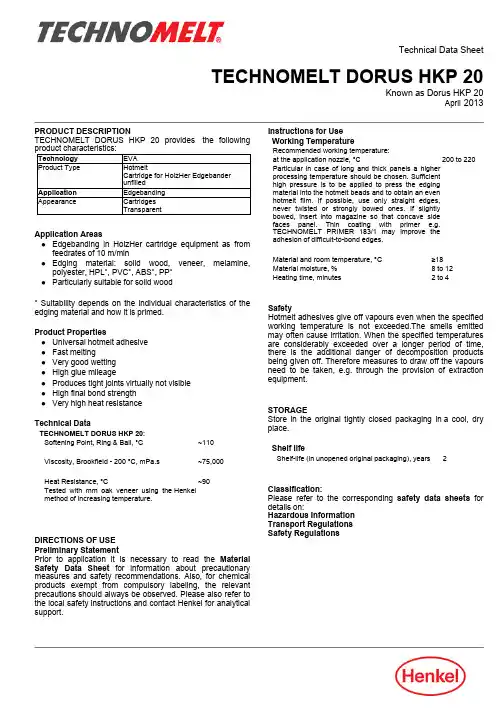
Technical Data SheetTECHNOMELT DORUS HKP 20Known as Dorus HKP 20April 2013PRODUCT DESCRIPTIONTECHNOMELT DORUS HKP 20provides the following product characteristics:Technology EVA Product Type HotmeltCartridge for HolzHer Edgebander unfilledApplication Edgebanding AppearanceCartridges TransparentApplication Areas●Edgebanding in HolzHer cartridge equipment as from feedrates of 10m/min●Edging material:solid wood,veneer,melamine,polyester,HPL*,PVC*,ABS*,PP*●Particularly suitable for solid wood*Suitability depends on the individual characteristics of the edging material and how it is primed.Product Properties●Universal hotmelt adhesive ●Fast melting●Very good wetting ●High glue mileage●Produces tight joints virtually not visible ●High final bond strength ●Very high heat resistance Technical DataTECHNOMELT DORUS HKP 20:Softening Point,Ring &Ball,°C ~110Viscosity,Brookfield - 200°C,mPa.s~75,000Heat Resistance,°C ~90Tested with mm oak veneer using the Henkel method of increasing temperature.DIRECTIONS OF USE Preliminary StatementPrior to application it is necessary to read the Material Safety Data Sheet for information about precautionary measures and safety recommendations.Also,for chemical products exempt from compulsory labeling,the relevant precautions should always be observed.Please also refer to the local safety instructions and contact Henkel for analytical support.Instructions for Use Working TemperatureRecommended working temperature:at the application nozzle,°C 200 to 220Particular in case of long and thick panels a higher processing temperature should be chosen.Sufficient high pressure is to be applied to press the edging material into the hotmelt beads and to obtain an even hotmelt film.If possible,use only straight edges,never twisted or strongly bowed ones.If slightly bowed,insert into magazine so that concave side faces panel.Thin coating with primer e.g.TECHNOMELT PRIMER 183/1may improve the adhesion of difficult-to-bond edges.Material and room temperature,°C ≥18Material moisture,%8 to 12Heating time,minutes2 to 4SafetyHotmelt adhesives give off vapours even when the specified working temperature is not exceeded.The smells emitted may often cause irritation.When the specified temperatures are considerably exceeded over a longer period of time,there is the additional danger of decomposition products being given off.Therefore measures to draw off the vapours need to be taken,e.g.through the provision of extraction equipment.STORAGEStore in the original tightly closed packaging in a cool,dry place.Shelf lifeShelf-life (in unopened original packaging),years2Classification:Please refer to the corresponding safety data sheets for details on:Hazardous Information Transport Regulations Safety RegulationsTDS TECHNOMELT DORUS HKP20, April2013 ADDITIONAL INFORMATIONDisclaimerNote:The information provided in this Technical Data Sheet(TDS)including therecommendations for use and application of the product are based on ourknowledge and experience of the product as at the date of this TDS.Theproduct can have a variety of different applications as well as differingapplication and working conditions in your environment that are beyond ourcontrol.Henkel is,therefore,not liable for the suitability of our product for theproduction processes and conditions in respect of which you use them,as wellas the intended applications and results.We strongly recommend that youcarry out your own prior trials to confirm such suitability of our product.Any liability in respect of the information in the Technical Data Sheet or anyother written or oral recommendation(s)regarding the concerned product isexcluded,except if otherwise explicitly agreed and except in relation to deathor personal injury caused by our negligence and any liability under anyapplicable mandatory product liability law.In case products are delivered by Henkel Belgium NV,Henkel ElectronicMaterials NV,Henkel Nederland BV,Henkel Technologies France SASand Henkel France SA please additionally note the following:In case Henkel would be nevertheless held liable,on whatever legal ground,Henkel’s liability will in no event exceed the amount of the concerned delivery.In case products are delivered by Henkel Colombiana,S.A.S.thefollowing disclaimer is applicable:The information provided in this Technical Data Sheet(TDS)including therecommendations for use and application of the product are based on ourknowledge and experience of the product as at the date of this TDS.Henkel is,therefore,not liable for the suitability of our product for the productionprocesses and conditions in respect of which you use them,as well as theintended applications and results.We strongly recommend that you carry outyour own prior trials to confirm such suitability of our product.Any liability in respect of the information in the Technical Data Sheet or anyother written or oral recommendation(s)regarding the concerned product isexcluded,except if otherwise explicitly agreed and except in relation to deathor personal injury caused by our negligence and any liability under anyapplicable mandatory product liability law.In case products are delivered by Henkel Corporation,Resin TechnologyGroup,Inc.,or Henkel Canada Corporation,the following disclaimer isapplicable:The data contained herein are furnished for information only and are believedto be reliable.We cannot assume responsibility for the results obtained byothers over whose methods we have no control.It is the user's responsibility todetermine suitability for the user's purpose of any production methodsmentioned herein and to adopt such precautions as may be advisable for theprotection of property and of persons against any hazards that may beinvolved in the handling and use thereof.In light of the foregoing,HenkelCorporation specifically disclaims all warranties expressed or implied,including warranties of merchantability or fitness for a particularpurpose,arising from sale or use of Henkel Corporation’s products.Henkel Corporation specifically disclaims any liability for consequentialor incidental damages of any kind,including lost profits.The discussionherein of various processes or compositions is not to be interpreted asrepresentation that they are free from domination of patents owned by othersor as a license under any Henkel Corporation patents that may cover suchprocesses or compositions.We recommend that each prospective user testhis proposed application before repetitive use,using this data as a guide.Thisproduct may be covered by one or more United States or foreign patents orpatent applications.Trademark usageExcept as otherwise noted,all trademarks in this document are trademarks ofHenkel Corporation in the U.S.and elsewhere. ®denotes a trademarkregistered in the U.S.Patent and Trademark Office.Reference0.0Henkel AG&Co.KGaA Henkel Corporation Henkel(China)Co.Ltd.73438Bopfingen,Germany Bridgewater,NJ08807,USA 201203Shanghai,ChinaPhone:+49-7362-81-0 Phone:+1-908-685-7000 Phone:+86-21-2891-8000For more information contact us on 。

物鏡釋放鈕照明設定切換鍵(同軸光源亮度/低角度光源亮度/低角度光源角度設定)Canon IXUS 800IS/950IS 可更換式物鏡同軸光源(MAIN)種類顯示相機固定螺絲同軸光源種類選擇鍵W : 白光F : 白光(標準版)/ 特殊功能光(選項)切換至低角度光源角度選擇下調至關閉全部低角度光源切換至同軸光源(MAIN)調整亮度1~5(檢視LCD)可切換四或八顆LED(註二)註二;同軸光源可改裝成四顆白光LED和四顆特殊功能燈 。
切換至同軸光源 調整亮度至 0(檢視LCD)切換至低角度光源切換至低角度光源角度選擇選擇光源角度調整亮度至 1~5(檢視LCD)拍攝立體表面物品(一)住快門鈕,然後按下 鍵,螢幕上會出現 AFL 圖標。
適用於X-LOUPE 裝於垂直腳架上,只轉動腳架上的旋鈕,自尋焦點。
基本設定為 0,可曝光補償正負兩格,快門速度(1. 若要在相片上加入時間、日期,CANON只2. 進入選單開啟日期印記進行拍攝後,時間與相機拍攝畫素:2592x1944dpi 約520萬畫素;量1mm的影像長度為19cm,即放大190倍。
相機拍攝畫素:3264x2448dpi 約799萬畫素;量1mm的影像長度為25cm,即放大250倍。
相機拍攝畫素:2592x1944dpi 約520萬畫素;啟動數碼遠攝功能:2.0x;量0.5mm的影像長度為19cm,即放大380倍。
相機拍攝畫素:3264x2448dpi 約799萬畫素;啟動數碼遠攝功能:2.0x;量0.5mm的影像長度為25cm,即放大500倍。

SHIMADZU AOC-20Clarity Control Module ENGCode/Rev.:M090/90BDate:10/2/2023DataApex Ltd. Phone:+420251013400Petrzilkova2583/13 ********************15800Prague5 The Czech RepublicClarity®,DataApex®and®are trademarks of DataApex Ltd.Microsoft®and Windows TM aretrademarks of Microsoft Corporation.DataApex reserves the right to make changes to manuals without prior notice.Updated manuals can be downloaded from .Author:MPContents1Shimadzu AOC-20i/s/d Control module1 2Requirements2 3Installation Procedure33.1Autosampler Setup-communication33.1.1Connections43.2Clarity Configuration54Using the control module74.1Hardware Configuration dialog74.2Method Setup-AS84.3Shimadzu AOC-20i/s Setup105Sequence12 6Troubleshooting13To facilitate the orientation in the Shimadzu AOC-20manual and Clarity chromatography station, different fonts are used throughout the manual.Meanings of these fonts are:Open File(italics)describes the commands and names of fields in Clarity,parameters that can be entered into them or a window or dialog name.WORK1(capitals)indicates the name of the file and/or directory.ACTIVE(capital italics)marks the state of the station or its part.Chromatogram(blue underlined)marks clickable links referring to related chapters.The bold text is sometimes also used for important parts of the text and the name of the Clarity station.Moreover,some sections are written in format other than normal text.These sections are formatted as follows:Note:Notifies the reader of relevant information.Caution:Warns the user of possibly dangerous or very important information.▌Marks the problem statement or trouble question.Description:Presents more detailed information on the problem,describes its causes, etc.Solution:Marks the response to the question,presents a procedure how to remove it.Shimadzu AOC-201Shimadzu AOC-20i/s/d Control module 1Shimadzu AOC-20i/s/d Control module This manual describes the setting of the Shimadzu AOC-20i/s/d autosamplers.The control module enables direct control of the instrument over serial line.Fig.1:AOC-20iDirect control means that the autosampler can be completely controlled from the Clarity environment.Instrument method controlling for example the vials and further device specific functions(e.g.washing)will be saved in the measured chromatograms.Shimadzu AOC-202Requirements2Requirementsl Clarity Installation with AS Control module(p/n A26).l Free serial port in the PC(fast-16550UART).Note:Modern computers usually have only1(if any)serial(COM)port installed.To use more devices requiring the port,the MultiCOM adapter(p/n MC01)is available.l Serial cross DB9F-DB9F cable(p/n SK01).Note:Cables are not part of Clarity Control Module.It is strongly recommended to order required cables together with the Control Module.Caution:We have experienced power sources(controller boards)with DB9F connector on the back instead of normal DB9M connector.In that case,serial cross DB9M-DB9F cable is necessary.Contact our support on******************to consultthe correct wiring.3Installation Procedure3.1Autosampler Setup-communicationThe autosampler communicates with PC using the RS232-compliant serial cross DB9F-DB9F cable.Fig.2:Serial cross DB9F-DB9F cableThe RS-232cable is plugged in to the autosampler controller board(not the tower) present at the back side of the GC,replacing the cable connecting it to the GC in default setup,as displayed in the Fig.3on pg.3.Fig.3:Shimadzu AOC-20controller board connections3.1.1ConnectionsBesides the serial RS-232cable,the connections must be made between the autosampler Start OUT/Ready IN connector and the appropriate connectors on the GC to allow proper synchronization between the AS and GC.l The Clarity Start(IN)input must be connected to the GC Start Out connector.l The Clarity Ready(OUT)digital output is not used,the commands are transmitted over the serial line.Refer to Shimadzu manual for description of cables supplied with the autosampler.When autosampler has to be used with Shimadzu201x series GCs( 2010,2014, 2014C,2014APC/AFC),it is necessary to connect it to the PC via separate serial line.The controller box is build in the GC2010/2014case,but to use the control from Clarity,the short serial cable from the GC to the controller box needs to be disconnected and replaced by a serial cable to the PC.3.2Clarity ConfigurationFig.4:How to add Shimadzu AOC-20l Start the Clarity station by clicking on the icon on the desktop.l Invoke the System Configuration dialog accessible from the Clarity window using the mand.l Press the Add button①(see Fig.4on pg.5.)to invoke the Available Control Modules dialog.l You can specify the searching filter②to simplify the finding of the driver.l Select the AOC-20sampler and press the Add③button.The Shimadzu AOC-20i/s Setup dialog will appear.Fig.5:Shimadzu AOC-20i/s Setupl Select the correct Port,Baud Rate,Parity and Stop bit settings for the autosampler.Then press the Connect button.If the communication is correct,the status of the autosampler will appear in the Connection row.Note:The Shimadzu AOC-20i/s Setup dialog is more closely described in the chapter "Shimadzu AOC-20i/s Setup"on pg.10.The AOC-20autosampler item will appear in the Setup Control Modules list of the System Configuration dialog.l Drag and drop the AOC-20icon from the Setup Control Modules④list on the left side of the System Configuration dialog to the desired Instrument⑤tab on the right side⑥(or use the button⑦to do so).4Using the control moduleNew Method Setup-AS tab appears in the Method Setup dialog,enabling the setting of the AS control method.The From AS and To AS buttons serve for transfer of methods from and to autosampler.Caution:If you have injection methods already established in the sampler,it is advisable to download them to Clarity using the From AS button and save them as a Claritymethod.The AS Status button displays the Hardware Configuration dialog.4.1Hardware Configuration dialogFig.6:Hardware ConfigurationThis dialog displays automatically detected communication port.4.2Method Setup-ASFig.7:Method Setup-AS-Parameters Dwell timeWaiting time after sample injection.Valid range:0-99.9sRinse with sampleSample washing times of the syringe before injection.Valid range:0-99Rinse with solventSolvent washing times of the syringe after injection.Valid range:0-99Viscosity timeWaiting time of the plunger after sample suction.Valid range:0-99.9sPump syringeNumber of pumpings.Valid range:0-99Plunger injection speedInjection speed of the plunger.Plunger suction speedPlunger suction speed at sample suction.Injection typeInjection type.Standard-sample+(air)Solvent flush-solvent+air+sample+(air)Solvent flush w/o air-solvent+sample+(air)Standard internal-solvent+air+standard sample+air+sample+(air)Standard internal w/o air-solvent+standard sample+sample+(air)Syringe injection speedInjection speed of the syringe.Select SolventSelects the appropriate solvent for solvent wash in case there are three solvent vials on the sampler rack.It is necessary to enable this option in the Shimadzu AOC-20i/s Setup dialog using the Use three solvents checkbox.Air SuctionCheck if you want autosampler to suck air into the needle after sample suction.This can help prevent premature evaporation of part of the sample,when the needle is warmed-up.4.3Shimadzu AOC-20i/s SetupThe Shimadzu AOC-20i/s Setup dialog sets the fundamental options of the control module.Note:It is accessible from the System Configuration dialog by doubleclicking the Shimadzu AOC-20i/s item.Fig.8:Shimadzu AOC-20i/s SetupPortCOM Port used for communication between the hardware and the PC.Baud Rate,Parity,Stop BitCommunication parameters.Those parameters should be set according to the actual communication parameters set in the autosampler(use the Function key to check/modify them)Default values:Baud rate:2400(F80=2)Parity:none(F81=0)Stop bits:2(F82=1)Note:The changes made on the sampler are active only after power restart.ConnectButton which tests communication with auto-injector hardware and detects if auto-sampler hardware is present.First fill in the COM Port,Baud rate,Parity,Stop bit fields and check AOC17mode if you need AOC-17compatible mode,then press the Connect button.Now connection is tested and auto-sampler is detected for established connection.Connection state is shown in the Connection field.If connection fails then message box appears and you are asked to check some parameters on the hardware.ConnectionConnection status.Sampler nameAssigns name to the sampler,under which it appears in configuration,method setup,reports,etc.ModelDefines the model of the AOC-20sampler.Vial sizeDefines the type of the vials used on the sampler.Syringe typeDefines the type of the syringe.AOC-17modeSetting this checkbox enables AOC-17compatible mode.To use the AOC20in this mode,set the functions F84=1(default is F84=0).Note:Regardless of mode used,the Channel1Protocol parameter must be zero (F83=0).Use three solventsDefines whether the autosampler uses the three-vial solvent option or not.When checked,additional options will be available on the Method Setup-AS tab for selecting the solvent vials for pre-wash and post-wash.Shimadzu AOC-205Sequence 5SequenceTo use the autosampler in the Clarity sequence,following conditions must be met:l The sequence must be savedl The sequence must be set as Active Sequencel All used methods must have the External Start enabled and the Autostop time setl Method Setup-AS dialog in the used methods must be filled The required values for starting vial(SV),ending vial(EV),number of injections from vial(I/V)and injected volume are set in the sequence table.Standard sequence operationAfter sequence start,the AS control method will be sent to the sampler and the datastation will wait for the injection signal from sampler.After receiving it,the run starts and after finishing,the method for next injection will be sent to the sampler.Note:Communication protocol used for autosampler control in Clarity allows wider possibilities for some parameters(for example Minimum injection volume)compared to original manufacturer's User manual.Shimadzu AOC-206Troubleshooting 6TroubleshootingWhen the cause could not be discovered easily,the recording of communication between Clarity and the autosampler can significantly help the DataApex support to discover the cause.The recording can be enabled by adding or amending the COMMDRV.INI file in the Clarity installation directory(C:\CLARITY\CFG by default).The file can be edited in any text editor(e.g.Notepad).Following lines should be added[COM1]echo=ontextmode=onfilename=CommDrv_%D.txtreset=offNote:Instead of COM1type the correct serial port used to communicate with the Shimadzu AOC-20detector.Note:%D(or%d)in the filename parameter means that the log will be created separately for each day.The reset=off parameter disables deleting the content ofthe log each time the station is started during the same day.The created LOG files will greatly help in diagnosis of unrecognized errors and problems in communication.Recording the communication related to instrument control is not recommended to leave it on for prolonged periods.。

EAN:4013288098917Size:170x80x55 mmPart number:Weight:266 gArticle number:KK 20Country of origin:CZ82079030Customs tariffnumber:Kraftform holder with bayonet blade and Rapidaptor quick-release chuckKraftform handle with anti-roll feature, multi-component and integrated magazineTough viscous bits for universal useIn robust pouchRetractable bayonet bladeWera compact tools enable both manual as well as power tool operations at the same time. The handle/interchangeable blade system in a compact design with various blade tips in the smallest of spaces makes the user more mobile and flexible. Suitable for bits with 1/4" hexagon head drive as per DIN ISO 1173-C 6.3 and E 6.3 (ISO 1173) and Wera connecting series 1 and 4. Comes with an adaptor, bayonet and Rapidaptor technology. Kraftform handle with anti-roll feature, multi-component for particularly ergonomic screwdriving. Integrated magazine for bit storage. In this way, the set replaces a 6-piece screwdriver set and reduces the equipment required to a minimum. The telescopic bayonet blade – which can be lowered into the handle – together with the quick-release chuck allows fast manual work even in confined installation situations when the blade is retracted. The blade can be extended by simply actuating the locking sleeve. The bayonet holder can then be used as a fully-fledged screwdriver. The bayonet blade can be removed and used as a power tool adaptor, but can also be retracted once again to its original position. Includes practical belt pouch.Web linkhttp://products.wera.de/en/kraftform_kompakt_kraftform_kompakt_20_22_25_26_28_kk_20.htmlSet contents:889/4 R***********1 x 1/4" x 100 mm851/1 Z PH *********** 1 x PH 1 x 25 mm ***********1 x PH2 x 25 mm855/1 Z PZ *********** 1 x PZ 1 x 25 mm ***********1 x PZ2 x 25 mm 800/1 Z*********** 1 x 1 x 5,5 x 25 mm ***********1 x 1,2 x 6,5 x 25 mmTelescopic blade, integrated bit magazine, Rapidaptor technologyManual and power tool operations Handle/interchangeable bladesystemWhy is the right tool so often not at hand?The reason:too many tools and overly-heavy tool bags can make it bothersome to carry them onsite.So for us it was a clear challenge:to design a tool that is suitable for a whole host of applications and can be easily taken along to jobs at other sites.Our solution:Kraftform Kompakt tools.A handle into which blades with a range of different profiles can be pactly and protectively housed in a light and robust textile pouch or plastic box.The sets in the series Kraftform Kompakt 20are really something.A 2position telescopic blade can be retracted into the handle for confined space operation or extended for more reach.It can also be removed and used as a 100mm bit holder in the power tool.Six bits are conveniently integrated into a push-button opening bit magazine.The Rapidaptor technology ensures rapid one hand bit changes,press-in auto bit lock and a secure positioning when used in power tools thanks to the free-turning sleeve.The sets come with a Kraftform handle,quick-release chuck and bits for manual and power tool operations.The handle/interchangeable blade system allows rapid exchange of the blades required for a wide range of applications.Web linkhttp://products.wera.de/en/kraftform_kompakt_kraftform_kompakt_20_22_25_26_28_kk_20.htmlThe telescopic blade IThe telescopic blade IIThe telescopic blade IIIRapidaptor holderWhen the unique telescopic blade is lowered into the handle,fast,easy screw-driving action is possible,even in the tightest spots!By pushing the clamping sleeve,the telescopic blade can be extended out of the handle and the compact tool becomes a full-sized screwdriver.If the clamping sleeve is pushed again the telescopic blade can be taken out of the handle,and be used as a machine bit adaptor.Rapid bit change without needing any additional tools.One-hand operation with a freely spinning sleeve for simplified guidance of the tool.Web linkhttp://products.wera.de/en/kraftform_kompakt_kraftform_kompakt_20_22_25_26_28_kk_20.html。

FM11NT020NFC Forum Type2 Tag芯片技术手册2013. 08本资料是为了让用户根据用途选择合适的上海复旦微电子集团股份有限公司(以下简称复旦微电子)的产品而提供的参考资料,不转让属于复旦微电子或者第三者所有的知识产权以及其他权利的许可。
在使用本资料所记载的信息最终做出有关信息和产品是否适用的判断前,请您务必将所有信息作为一个整体系统来进行评价。
采购方对于选择与使用本文描述的复旦微电子的产品和服务全权负责,复旦微电子不承担采购方选择与使用本文描述的产品和服务的责任。
除非以书面形式明确地认可,复旦微电子的产品不推荐、不授权、不担保用于包括军事、航空、航天、救生及生命维持系统在内的,由于失效或故障可能导致人身伤亡、严重的财产或环境损失的产品或系统中。
未经复旦微电子的许可,不得翻印或者复制全部或部分本资料的内容。
今后日常的产品更新会在适当的时候发布,恕不另行通知。
在购买本资料所记载的产品时,请预先向复旦微电子在当地的销售办事处确认最新信息,并请您通过各种方式关注复旦微电子公布的信息,包括复旦微电子的网站(/)。
如果您需要了解有关本资料所记载的信息或产品的详情,请与上海复旦微电子集团股份有限公司在当地的销售办事处联系。
商标上海复旦微电子集团股份有限公司的公司名称、徽标以及“复旦”徽标均为上海复旦微电子集团股份有限公司及其分公司在中国的商标或注册商标。
上海复旦微电子集团股份有限公司在中国发布,版权所有。
目录目录 (3)1说明 (4)2产品综述 (5)2.1产品简介 (5)2.2产品特点 (5)2.2.1射频接口 (5)2.2.2EEPROM存储器 (5)2.2.3NFC Forum Type2 Tag兼容性 (5)2.2.4场检测 (5)2.2.5安全特性 (5)2.3结构框图 (6)2.4引脚说明 (6)3功能描述 (8)3.1总体描述 (8)3.2存储器 (8)3.2.1UID (9)3.2.2Lock 设置 (9)3.2.3CC区 (10)3.2.4出厂配置 (10)3.3通信原理 (11)3.4指令系统 (12)3.4.1REQA (13)3.4.2WUPA (13)3.4.3ANTICOLLISION和SELECT(第一级) (14)3.4.4ANTICOLLISION和SELECT(第二级) (15)3.4.5READ (16)3.4.6HALT (16)3.4.7WRITE (17)3.4.8COMPATIBILITY WRITE (17)4电气参数 (19)4.1极限额定参数 (19)4.2推荐工作条件 (19)4.3电参数 (19)4.4存储器参数 (19)5典型应用 (20)6订货信息 (21)7封装信息 (22)7.1DFN4封装 (22)7.2TSOT封装 (23)版本信息 (24)上海复旦微电子集团股份有限公司销售及服务网点 (25)1 说明本文档为FM11NT020芯片技术手册。
***************/fgsProduct Name 14/15Applications• Chemical Processing Liquids • Food Processing Liquids • Potable Water •Cooling Water• Condensate Return • Industrial Wastewater • Mildly Corrosive Liquids •Crude Oil & Gas• Produced Water • Saltwater • CO 2Bell & SpigotMaterials and ConstructionRed Thread HP pipe is manufactured by the filament winding process using continuous glass filaments saturated with aromaticamine-cured epoxy thermosetting resin. The pipe pressure rating is 290 psi in accordance with API 15LR, 20 year design life at 200°F (93°C). Serviceable up to 210°F (99°C) by applying a 0.92 derating factor to pipe and fittings.ASTM D-2996 Classification: RTRP-11AW1-3110FittingsFittings are manufactured with the same chemical and temperature capabilities as the pipe. Depending on the configurations and size, the fittings construction method will be compression molded, contact molded, fabricated or filament wound. Requires Red Thread/Green Thread HP 25 fittings. Details are in CI1360.Joinin g Sys tem• Bell & Spigot - The pipe and fittings are joined using an adhesive bonded taper-taper bell and spigot connection. Pipe is supplied with one end belled (integral bell or factory-bonded coupling) and one end tapered . The pipe is available in random 12 meter (40 feet) lengths.Epoxy adhesive available from NOV Fiber Glass Systems is used to secure the joint.• Flanged - Flanged connections are available for all components and diameters.View of Joint IllustrationsFlanged2Nominal Dimensional DataMaximum Support Spacing for Uninsulated Pipe (1)Example: Assuming a continuous span of 35.2 feet then with a 1.5 specific gravity fluid the maximum support spacing = 35.2 x 0.91 = 32.0 ft. (9.76 m)SupportsThe following engineering analysis must be performed to determine the maximum support spacing for the piping system. Proper pipe support spacing depends on the temperature and weight of the fluid carried in the pipe. The support spacing is calculated using continuous beam equations and the pipe bending modulus derived from long-term beam bending tests. The following tables were developed to ensure a design that limits beam mid-span deflection to ½ inch and bending stresses to less than or equal to 1/8 of the ultimate bending stress. Any additional weight on the piping system such as insulation or heat tracing requires further consideration. Restrained (anchored) piping systems operating at elevated temperatures often result in guide spacing requirements that are more stringent than simple unrestrained piping systems. In this case, the maximum guide spacing will dictate the support/guide spacing requirements for the system. Pipe support spans at changes in direction require special attention. Supported and unsupported fittings. at changes in direction are considered in the following tables and must be followed to properly design the piping system.Support Spacing vs. Specific Gravity3***************/fgsThere are seven basic rules to follow when designing piping system supports, anchors, and guides:1. Do not exceed the recommended support span.2. Support valves and heavy in-line equipment independently. This applies to both vertical and horizontal piping.3. Protect pipe from external abrasion.4. Avoid point contact loads5. Avoid excessive bending. This applies to handling, transporting, initial layout, and final installed position.6. Avoid excessive vertical run loading. Vertical loads should be supported sufficiently to minimize bending stresses at outlets or changes in direction.7. Provide adequate axial and lateral restraint to ensure line stability during rapid changes in flow.Adjustment Factors for Various Spans WithUnsupported Fitting at Change in Direction*For example: If continuous support is 10 ft. (3.04 m), A+B must not exceed 7.5 ft.(2.28 m) (A=3 ft.(0.91 m) and B=4.5 ft. (1.37 m)) would satisfy this condition.Adjustment Factors for Various Spans With SupportedFitting at Change in DirectionThermal ExpansionThe effects of thermal gradients on piping systems may be significant and should be considered in every piping system stress analysis. Pipeline movements due to thermal expansion or contraction may causeTestingHydrostatic testing is recommended to evaluate the integrity of all new piping installations. For systems operating below the system rating, a test pressure of 1.5 times the system operating pressure is recommended; however, the maximum test pressure must not exceed 1.5 times the lowest pressure rated fiberglass component in the piping system.The hydro test pressure should be repeated up to ten cycles from 0 psig to the test pressure to provide a high degree of confidence in the piping system. The final pressurization cycle should be allowed to stabilize for 15-30 minutes, then inspected for leaks. Do not attempt to repair leaks while system is pressurized. The hydro test should be repeated after any re-work is performed.When hydro testing, open high-point vents (if used) to prevententrapment of air in the lines as the system is slowly filled with water, then close the vents and slowly pressurize to the test pressure. Upon completion of hydro test, relieve the pressure on the system slowly, open vents and any drains to allow for complete drainage of the system.Water HammerPiping systems may be damaged by pressure surges due to water hammer. The use of soft start pumps and slow actuating valves will reduce the magnitude of surge pressures during operation and are highly recommended.high stresses or even buckle a pipe line if improperly restrained. Several piping system designs are used to manage thermal expansion and contraction in above ground piping systems. They are listed below according to economic preference:1. Use of inherent flexibility in directional changes.2. Restraining axial movements and guiding to prevent buckling.3. Use expansion loops to absorb thermal movements.4. Use mechanical expansion joints to absorb thermal movements.To perform a thermal analysis the following information is required:1. Isometric layout of piping system 2. Physical and material properties of pipe 3. Design temperatures4. Installation temperature (Final tie in temperature)5. Terminal equipment load limits6. Support movementsA comprehensive review of temperature effects on fiberglass pipe may be found in NOV Fiber Glass Systems’ Engineering and Piping Design Guide, Section 3.4Red Thread HP 20 - Product Data***************/fgsFiber Glass Systems17115 San Pedro Avenue, Ste 200San Antonio, Texas 78232 USA Phone: 210 477 7500Fax: 210 477 7560National Oilwell Varco has produced this brochure for generalinformation only, and it is not intended for design purposes. Although every effort has been made to maintain the accuracy and reliability of its contents, National Oilwell Varco in no way assumes responsibility for liability for any loss, damage or injury resulting from the use of information and data herein nor is any warranty expressed or implied. Always cross-reference the bulletin date with the most current version listed at the web site noted in this literature.© 2017 National Oilwell Varco All rights reserved CI1220ENG December 2017Ultimate Collapse PressurePipe Property75°F 24°C 200°F 93°C Methodpsi MPa psi MPa Axial Tensile Ultimate Stress9,53065.76,58545.4ASTM D2105Modulus of Elasticity 1.68 x 10611,5841.42 x 1069,791ASTM D2105Poisson’s Ratio , νah (νha )(1)0.35 (0.61)Axial Compression Ultimate Stress12,51086.38,56059.0ASTM D695Modulus of Elasticity 0.677 x 1064,6680.379 x 1062,613ASTM D695Beam BendingModulus of Elasticity (Long Term) 2.6 x 10617,9270.718 x 1064,951ASTM D2925Hydrostatic BurstUltimate Hoop Tensile Stress 40,15027736,480252ASTM D1599Hydrostatic Hoop Design Stress Static 20 Year Life LTHS - 95% LCL --18,203 - 14,689125.5 - 101.3ASTM D2992 - Procedure B Static 50 Year Life LTHS - 95% LCL --16,788 - 13,142115.7 - 90.6ASTM D2992 - Procedure B Parallel PlateHoop Modulus of Elasticity 3.02 x 10620,822--ASTM D2412TorsionalShear Modulus 1.76 x 10612,135 1.63 x 10611,240NOV/FGS Ultimate Stress19,000131.018,500127.6NOV/FGSPipe Property ValueValue Method Thermal Conductivity 0.23 BTU/hr•ft•°F 0.4 W/m°CASTM D177Thermal Expansion 10.7 x 10⁻⁶ in/in/°F 19.3 x 10⁻⁶ mm/mm/°C ASTM D696Absolute Roughness 0.00021 in0.00053 mm Specific Gravity1.8ASTM D792Typical Mechanical PropertiesTypical Physical PropertiesSize Collapse Pressure (2,3,4)psig MPa In mm 75°F 200°F 24°C 93°C 820035250.2410.1721025032230.2210.1591230031220.2140.1521435048350.3310.2411640051370.3520.2551845035260.2410.1792050028200.1930.1382460028200.1930.138(1)νha = The ratio of axial strain to hoop strain resulting from stress in the hoop direction. νah = The ratio of hoop strain to axial strain resulting from stress in the axial direction.(2) The differential pressure between internal and external pressure which causes collapse.(3)A 0.67 design factor is recommended for short duration vacuum service. A full vacuum is equal to 14.7 psig (0.101 MPa) differential pressure at sea level.(4)A 0.33 design factor is recommended for sustained (long-term) differential collapse pressure design and operation.。
UNC20 Module User's ManualP.O: Box 1103 Kueferstrasse 8 Tel. +49 (7667) 908-0 ****************• D-79200 Breisach, Germany • D-79206 Breisach, Germany • Fax +49 (7667) 908-200• http://www.fsforth.deUNC20 Module User's ManualCopyright 2003:FS Forth-Systeme GmbHPostfach 1103, 79200 Breisach, GermanyRelease of Document:July 14, 2003Filename:UNC20_MOD_UM.docAuthor:N. JamesBoard Revision:UNC20_1All rights reserved. No part of this document may be copied or reproduced in any form or by any means without the prior written consent of FS Forth-Systeme GmbH.2UNC20 Module User's Manual Table of Contents1.General (4)2.Features (4)3.Detailed Description (5)3.1.NS7520 Processor (5)3.2.Memory (5)3.3.Ethernet Interface (5)3.4.Timers (6)3.5.General purpose I/O (6)3.6.Serial Interface (6)3.7.I2C (7)3.8.JTAG interface (7)3.9.Reset (7)3.10.External peripheral bus (7)3.11.Voltage Requirements (7)4.UNC20 Connector (8)5.GPIO Configuration of UNC20 (10)6.Temperature and Power Specifications (12)7.Mechanical Information (12)3UNC20 Module User's Manual1. GeneralThe Universal Network Controller (UNC20) has been designed for embedded systems requiring network connectivity. The UNC20 module is housed in an industry-standard DIL48 package, making it extremely easy and cost-effective to integrate into designs which require Ethernet connectivity.This document refers to the UNC20 modules with the Part Numbers 352 and 355.2. Features•NetSilicon's NS7520 microcontroller•Up to 16Mbytes SDRAM, 32-bit wide•Up to 8Mbytes Flash memory, 16-bit wide•PHY for 10/100 Ethernet•Two serial interfaces•Serial EEPROM (8KBytes) for storing configuration parameters• I2C port•Up to 16 programmable digital I/O pins (multiplexed with other functions)• JTAG interface•External 8-bit data bus, 10-bit address bus and 2 external chip selects •Single power supply of +3.3V required4UNC20 Module User's Manual 3. Detailed Description3.1. NS7520 ProcessorThe CPU is an ARM7TDMI 32-bit RISC core running at 55MHz with a rich complement of peripherals on-chip.For more information on this device please consult the NS7520_HR.pdf document.The ARM7TDMI is capable of operating in both little-endian and big-endian modes. The standard UNC20 modules, currently Part Numbers 352 and 355, are factory-configured to boot in big-endian mode.3.2. MemoryThe UNC20 is assembled with 16Mbytes of 32-bit wide SDRAM. A 16-bit wide Flash device is assembled. Currently 2 variants of the UNC20 are available, one with 2MB Flash (P/N 355) and one with 8MB Flash (P/N 352).3.3. Ethernet InterfaceThe NS7520 contains a 10/100 Ethernet MAC which is conform to the IEEE802.3 standard. Included on-chip are a 512-byte transmit FIFO and 2-Kbyte receive FIFO for maximizing Ethernet throughput. Full-duplex and half-duplex modes are supported for both 10Mbps and 100 Mbps operations as is address filtering for broadcasts and multicasts.The PHY on the module supports auto-negotiation and can drive a 100Base-Tx line or a 10Base-T line. The UNC20 provides 4 pins for connecting a Twisted-Pair RJ-45 interface using an external transformer with a 1:1 turns ratio.5UNC20 Module User's Manual3.4. TimersTwo independent 27-bit timers are provided in the NS7520. These can be programmed to generate interrupts after expiration of time periods ranging from 2us to 20 hrs. Both timers can be programmed to generate an interrupt to the ARM core on either the IRQ or FIQ signals.3.5. General purpose I/OTwo 8-bit ports (A and C) are available for digital I/O. All pins are multi-function and can be individually configured. Pins C2 and C6 are reserved for the I2C bus. The other 14 pins can be freely configured by the user and may be used to implement a serial interface, for example. Pins C0, C1 and C3 can be used to generate a level-sensitive interrupt to the ARM core's IRQ signal.3.6. Serial InterfaceTwo independent serial channels are available in the NS7520. These channels can operate in the following modes:UART at speeds up to 230 kbits/sec, with 5 to 8 data bits; odd, even or no parity;1 or2 stop bits.HDLC at speeds up to 4 MbpsSPI (Serial Peripheral Interface) - this full-duplex synchronous 4-wire interface can be used to connect various peripherals to the UNC20.The pins for the 2 serial channels are multiplexed with the 16 General Purpose I/O pins. Serial channel 1 is on Port C and the following signals are available: RxD, TxD, RTS, CTS, DCD, RI. Only 6 signals are available since 2 pins are used by the I2C interface. Serial channel 2 is on Port A and the same signals are available plus DSR and DTR. All signals are 3.3V TTL levels.6UNC20 Module User's Manual 3.7. I2CAn I2C bus is available on pins 17 (SDA) and 21 (SCL). Any 3.3V I2C device can be connected to these pins provided that they do not use address 0xA0 which is being used by an 8-kByte EEPROM on the UNC20. The I2C bus can operate at speeds of 100 kbit/sec (Standard mode).3.8. JTAG interfaceThis interface is primarily used for debug purposes. The 5 pins TCK, TMS, TDI, TDO and TRST# are multiplexed with 5 address lines and are available on pins 2 through 6. Selection of the JTAG signals is achieved by tying pin 30 (LEDLNK/SEL#) low. When pin 30 is not tied to GND it is the LEDLNK output from the PHY and is used to drive an LED on the base board to denote Ethernet link and activity.3.9. ResetA power-on reset generator resets all components on the module. The RESET# signal is output on pin 25 so that it can be used to reset components on the base board at power-on. The RESET# signal is bi-directional thus allowing devices on the base board, such as a reset switch, to reset the module. The RESET# signal can sink 5mA and source 150uA. These values must not be exceeded.3.10. External peripheral busAn 8-bit data bus and 10-bit address bus are provided for connecting external peripherals to the UNC20. Two individually programmable chip selects and an OE# (Output Enable) and WE# (Write Enable) signal allow a vast range of 8-bit peripherals to be connected directly to the UNC20 without any glue logic.3.11. Voltage RequirementsFor the UNC20 module only a single 3.3V DC power supply is needed.7UNC20 Module User's Manual4. UNC20 ConnectorPin Signal Type Drive Description1ADDR4O4mA U2ADDR5/TCK O/I4mA U ADDR[5..9] are multiplexed 3ADDR6/TMS O/I4mA U With JTAG functionality 4ADDR7/TDI O/I4mA U Controlled by5ADDR8/TDO O/O4mA U LEDLNK/SEL signal6ADDR9/TRST#O/I4mA U7PORTA0I/O2mA U GPIO8PORTA1I/O2mA U GPIO9PORTA2I/O2mA U GPIO10PORTA3I/O2mA U GPIO11PORTA4I/O2mA U GPIO12PORTA5I/O2mA U GPIO13PORTA6I/O2mA U GPIO14PORTA7I/O2mA U GPIO15PORTC0I/O2mA U GPIO16PORTC1I/O2mA U GPIO17SDA O2mA U Hardwired - I2C data signal 18PORTC3I/O2mA U GPIO19PORTC4I/O2mA U GPIO20PORTC5I/O2mA U GPIO21SCL I/O2mA U Hardwired - I2C clock signal 22PORTC7I/O2mA U GPIO23 3.3V P 3.3V Power Connection24GND P Ground Connection8UNC20 Module User's Manual25RESET#I/O5mA U Reset (bidirectional)26TPIP I Ethernet Input+27TPIN I Ethernet Input-28TPOP O Ethernet Output+29TPON O Ethernet Output-30LEDLNK/SEL#O Ethernet Activity LED;ADDR/JTAG Selection: 31USB-I/O Reserved32USB+I/O Reserved33DATA31I/O4mA External data line D734DATA30I/O4mA D635DATA29I/O4mA D536DATA28I/O4mA D437DATA27I/O4mA D338DATA26I/O4mA D239DATA25I/O4mA D140DATA24I/O4mA D041ADDR0O4mA U Address Line42ADDR1O4mA U Address Line43ADDR2O4mA U Address Line44ADDR3O4mA U Address Line45WE#O4mA Write Enable46OE#O4mA Output Enable47CS3#O4mA Chip Select 348CS4#O4mA Chip Select 4The “U” in the Drive column denotes a pull-up resistor is present on this signal.9UNC20 Module User's Manual105. GPIO Configuration of UNC20GPIO Serial OTHER PIN Serial OTHERA7TxDA 14I/O Port A TxD A6DTRA_DREQ1_13I/O Port A DTR_DMA Chnl 3/5 ReqA5RTSA_12I/O Port A RTS_A4RxCA /RIA_ /OUT1A _11I/OPgmbl Out / Port A RxCLK / Port A Ring Signal / Port A SPI Clock (CLK)A3RxDA DACK1_10I/O Port A RxD DMA Chnl 3/5 Ack A2DSRA_AMUX9I/OPort A DSR_DRAM Addr Mux / USB Pwr Relay CtrlA1CTSA_DONE1_ (O)8I/O Port A CTS_DMA Chnl 3/5Done_OutA0TxCA /OUT2A _ /DCDA_DONE1_ (I)7I/OPgmbl Out / Port A DCD / Port A SPI Enable (SEL_) / Port A TxCLKDMA Chnl 3/5 DONE_InUNC20 Module User's Manual11C7TxDB 22I/O Port B TXD GEN Intrpt Out C6DTRB_DREQ2_21I/OPort B DTR_DMA Chnl 4/6 Req I2C clock signal (SCL )C5RTSB_REJECT _20I/O Port B RTS_CAM RejectC4RxCB /RIB_ /OUT1B _RESET_/19I/OPgmbl Out /Port B RxCLK /Port B Ring Signal / Port B SPI Clock (CLK)RESET Output C3*RxDB LIRQ3 /DACK2_18I/O Port B RxD Level Sensitive IRQ /DMA Chnl 4/6 Ack C2*DSRB_LIRQ2 /RPSF_17OPort B DSR_Level Sensitive IRQ /CAM Request I2C data signal (SDA )C1*CTSB_LIRQ1 /DONE2_(O)16I/O Port B CTS_Level Sensitive IRQ /DMA Chnl 4/6Done_OutC0*TxCB /OUT2B _ /DCDB_LIRQ0 /DONE2_(I)15I/OPgmbl Out /Port B DCD /Port B SPI Enable (SEL_)/ Port B TxCLKLevel Sensitive IRQ /DMA Chnl 4/6 DONE_InUNC20 Module User's Manual126. Temperature and Power SpecificationsCharacteristicMin Max Unit Operating Temperature (Ambient)070Degrees C Storage Temperature -50125Degrees C Power Consumption (at 3.3V)90280mA7. MechanicalInformationAll dimensions in mm.。
Parts Manual cFor Technical Assistance call: 800-227-2233, Fax: 888-329-8207 To Order Parts call: 888-227-2233, Fax: 888-329-023420D Appliance Clamp20D-ACS-115ModelSerial Number cascadeாcorporation123Safety DecalsPART NO.DESCRIPTION670487Service Manual 670834Operators Guide670488Installation Instructions680664Servicing Cascade Cylinders-VHS 679929Tool Catalog673964Literature Index Order FormPublicationsREF QTY PART NO.DESCRIPTION 11679150No Step Decal22665595No Hand Hold Decal31679059Quick Change Hook DecalBase Unit GroupREF QTY PART NO.DESCRIPTION370247Base Unit Group12686472Hose, 25.50 in.22206880Hose, 17.25 in.39601377Fitting, 8-841674168Frame - Lower52581555Plug63671222Capscrew, 3/8 NC x .75724071Capscrew82318595Cylinder v927861Roll Pin - Inner1027962Roll Pin - Outer111671549Frame - Upperv See Cylinder page for parts breakdown.Reference: Mounting Group 341425, Common Parts 318623, SK-5299.REF QTY PART NO.DESCRIPTION 128667910Washer138667909Capscrew141354983Bumper152665707Nut, 1/2 in. ID1623659Capscrew, 1/2 NC x 2.50174668910Bearing184667663Bearing194668911Bearing201680620Mounting Plate - RH211680619Mounting Plate - LH221316732Bracket231343684Valve q20Dq See Valve page for parts breakdown.REF QTY PART NO.DESCRIPTION343684Valve Group 11667490Special Fitting 212841O-Ring q 31667471Spool 42609453Fitting, 1052667487Spring 67604510Fitting, 671678270Check Valve – VPO 82659058Check Valve – PO 92667516Service Kit q101679846Low Flow Spool Kit 112667494Fittingq Included in Service Kit 667513.Valve GroupREF QTY PART NO.DESCRIPTION1222840O-Ring q 132673098Spring 142667492Poppet151673089Spool Assembly 162667491Sleeve 171343685Valve Body 181661347Service Kit q 191334615Relief Valve 201684625Service Kit 211343687Relief Valve 221667510Service Kit 667513Service Kit20DREF QTY PART NO.DESCRIPTION318595Cylinder Assembly 126510Cotter Pin s 22667624Nut Retainers 32667625Nut s 41318596Shell 51602580Fitting 61558200Piston 712716O-Ring v 81662452Seal v 912785O-Ring v101615128Back-Up Ring v 111563906Retainer 121662448Seal v131638243Nylon Ring v 141636853Wiper v 151667623Nut 161318597Rod 171667626Washer 181—Spacer191671047Seal Loader, Piston v 201671051Seal Loader, Retainer v 668021Service Kitv Included in Service Kit 668021.s Included in Nut Service Kit 668926.Reference: S-7605, S-7658CylinderArm Group20DREF QTY PART NO.DESCRIPTION6010454Arm Group 116010634Arm - RH 216010633Arm - LH 324607103Capscrew 44667905Arm BarBolt-On Mounting GroupClass IIREF QTY PART NO.DESCRIPTION678934Lower Hook Group12675968Lower Hook24667225Washer, 5/8 in. ID34667369Capscrew, 5/8 NC x 1.25 GR 5 Reference: S-3197.Mounting Plates with Bolt-On Upper HooksREF QTY PART NO.DESCRIPTION1 1 680619 Mounting Plate Assembly–LH q2 1 680620 Mounting Plate Assembly–RH s 316002330Upper Hook–LH 41210491Upper Hook–RH 54768577Capscrew, M20 x 35q Includes items3 and 5.sIncludes items 4 and 5.P A R T S O R D E R I N G L O GP U R C H A S E S E R I A L R E F C A S C A D E C U S T O M E R D A T EO R D E R N U M B E RP A G E N O .Q T Y P A R T N O .P A R T N O .D E S C R I P T I O N P R I C EDo you have questions you need answered right now? Call your nearest Cascade Parts Department.Cascade (UK) Ltd.15, Orgreave Crescent Dore House Industrial Estate HandsworthSheffield S13 9NQ EnglandTel: 742-697524FAX: 742-695121Cascade Scandinavia AB Box 124Hammarvägen 10567 23 Vaggeryd SwedenTel: 42-0-393-36950 FAX: 46-0-393-36959Cascade N.V. European Headquarters P.O. Box 30091300 El Almere Damsluisweg 561332 ED AlmereThe NetherlandsTel: 31-36-5492911 FAX: 31-36-5492964Cascade Norway Østerliveien 37A 1153 Oslo NorwayTel: 47-22-743160 FAX: 47-22-743157Cascade France S.A.R.L.1D Rue De CharaintruBP 18, 91360 Epinay-Sur-OrgeMorangis Cedex, FranceTel: 33-1- 64547500FAX: 33-1-64547501Cascade Hispania S.A.Carrer 5 Sector CZona Franca DuaneraPoligono de la Zon Franca08040 Barcelona, SpainOffice No. 256Tel: 93-264-07-30FAX: 93-264-07-31Cascade Canada Inc.5570 Timberlea Blvd.Mississauga, OntarioCanada L4W-4M6Tel: 905-629-7777FAX: 905-629-7785Cascade GmbHD-41199 MonchengladbachKlosterhofweg 52GermanyTel: 49-216-668230FAX: 49-216-6682323Cascade N.V.Benelux Sales and ServiceP.O. Box 30091300 El AlmereDamsluisweg 561332 ED AlmereThe NetherlandsTel: 31-36-5492950FAX: 31-36-5492974Cascade FinlandAlbert Petreliuksenkatu 301370 VantaaFinlandTel: 358-9-836-1925FAX: 358-9-836-1935Cascade Corporation2501 Sheridan AvenueSpringfield, OH 45505Tel:888-CASCADE (227-2233)FAX: 888-329-0234Cascade Japan Ltd.5-5-41,Torikai KamiSettsu, OsakaJapan, 566Tel: 81-726-53-3490FAX: 81-726-53-3497Cascade Korea108B, Namdong Ind Complex 658-3 Gojan-Dong Namdong-GuInchon, 405-310 KoreaTel: 82-32-821-2051FAX: 82-32-821-2055Cascade Australia1445 Ipswich RoadRocklea, QLD 4106AustraliaTel: 1-800227-223FAX: (07) 3373-7333Cascade New Zealand15 Ra Ora DriveEast Tamaki, AucklandNew ZealandTel: 9-273-9136FAX: 9-273-9137Cascade (Africa) Pty. Ltd.P.O. Box 625, Isando 160060A Steel RoadSparton, Kempton ParkSouth AfricaTel: 27-11-975-9240FAX: 27-11-394-1147Cascade-Xiamen No. 668 Yangguant Rd. Xinyang Industry Zone Haicant, Xiamen City Fujian ProvinceP.R. China 361026 Tel: 86-592-651-2500 FAX: 86-592-651-2571Cascade (Singapore) Trading Co.Four Seasons Park Autumn Block - Apt. 1802 12 Cuscaden Walk SingaporeTel: 65-834-1935FAX: 65-834-1936c。
NOTICEAbout Skin Sensing FunctionAbout Operating TimeThe continuous operating time of each mode is default.The time is not included under below circumstances:W hen the head or the head attached with cotton puffand back plate are not contacted with skin continuously T he cotton puff used does not contain enough toner T he actual operating time normally would be longer.Attention for UseMake sure to hold the main body of the product with your handtouching back plate and apply the head of the product to your skin. Otherwise, the product will not be operated.This product which is operated through the human body.T he electric circuit operates with skin in contact with the back plate and the head of the product.About Auto-off FunctionIf the product is not in operation around 5 minutes,the power will turn off automatically.There is an ending sound given and the product will turn off automatically when each mode is completed.Back plateFAQsNo.Questions AnswersQ1Tingling sensation is felt on the skin. Check the intensity level.If it is set on "High" level, press the level switchbutton to switch to "LOW" level.If toner in the cotton pad wears off, replenish it again.If you still feel uncomfortable on the skin, stop using the product immediately and consult adermatologist.Q2Can "CLEANSING"mode remove makeup? This product cannot remove makeup.Please use a makeup remover cleanser.Q3Will dirt be more easily removed by applyingmore force? Electric power is used for removing dirt and moisturizing. Thus, by applying more force, it will not make any difference.Gently apply to skin and massage slowly.Q4Cotton pad cannot be attached properly. Use a normal rectangular or round cosmetic cotton pad.(If the cotton pad is too thick or thin, it willnot be able to attach.)Q5Can the product be used in the bathroom? This product is not waterproof.Never use or place this product in wet and damp areas, e.g. bathroom.Q6Can I use milky lotion or gel? Milk-based lotion or gel can be used when using”MOISTURIZE” mode without cotton and ”MASK”mode.Please refer to the "About mode switching" in the"Preparation before use" section in the instructionmanual for details.Q7Does this product have whitening or blemishremoval function? This product is not for whitening or removing blemish.It will pull out fine dirt that remains deep in the pores and penetrate moisture into the skin.Q8Which regions are notsuitable to use this product? Please refer to the instruction manual for the list of regions.。