CREE(能源之星)T6、U2中文版规格书
- 格式:pdf
- 大小:2.23 MB
- 文档页数:14
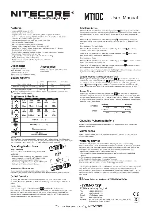
®User ManualFeatures• Utilizes a CREE XM-L2 U2 LED • Maximum output up to 920 lumens• Integrated metal micro textured reflector for optimal peripheral illumination• Boasts a peak beam intensity of 9,000 cd and a throw distance of up to 190 meters • Tail switch designed for tactical applications• Side switches for brightness levels and modes adjustment • Features intelligent memory effect• Red LED provides constant/flashing illumination• Displays battery voltage with red light (accurate to 0.1V)• High efficiency constant current circuit enables maximum runtime of 170 hours • Direct access to turbo/red light mode• Reverse polarity protection prevents damage from incorrectly inserted batteries • Stainless steel titanium-plated two-way clip• Toughened ultra-clear mineral glass with anti-reflective coating • Robust HAIII military grade hard-anodized• Waterproof in accordance with IPX-8 (two-meter submersible)• Tail stand capabilityDimensionsLength: 3.59” (91.2mm)Head Diameter: 1” (25.4mm)Tail Diameter: 1” (25.4mm)Weight: 2.01oz (57g)(without battery)Thanks for purchasing NITECORE!SYSMAX Industry Co., Ltd.TEL: +86-20-83862000 FAX: +86-20-83882723 E-mail: *****************Web: Address : Rm1401-03, Glorious Tower, 850 East Dongfeng Road,Guangzhou, China 510600Battery OptionsThe All-Round Flashlight ExpertBrightness LevelsWhen the MT10C is switched on, press the step-up switch repeatedly to switch from the following brightness levels: red beacon-red light-ultralow-low-medium-high-turbo. The MT10C has memory effect. When it is switched on, the MT10C will enter the brightness level last used.When the MT10C is switched on, press the step-down switch repeatedly to lower its brightness until red beacon mode, after which there is no cycling back to other brightness levels.Direct Access to Red Light Mode:When the MT10C is switched on, press and hold the step-down switch for over one second to access the red light mode; OR:When the MT10C is switched off, press and hold the step-down switch and press the button on the tailcap to access the red light mode.Direct Access to Turbo:When the MT10C is switched on, press and hold the step-up switch for over one second to access turbo output (920 lumens); OR:When the MT10C is switched off, press and hold the step-up switch and press the button on the tailcap to access turbo output (920 lumens).Note: After three minutes' using of turbo mode, the flashlight will lower its output automatically to prevent overheating, and efficiently ensure the battery runtime.Special modes (Strobe/Location/SOS)With the light switched on, press both side switches to enter strobe mode. When in strobe mode, press both side switches again to cycle through Location Beacon, SOS, and Strobe modes. To exit and resume the brightness level last used, simply press the step-up or step-down switch. The MT10C has memory effect in strobe mode. If it is turned off in strobe mode, it will enter strobe mode immediately when switched on again.Power TipsWith the light switched off, press both side switches and the button on the tailcap to activate the red power indicator to blink and indicate battery voltage (accurate to 0.1V). For example, when battery voltage is at 4.2V, the red power indicator will blink 4 times, followed by a one second pause and another 2 blinks. Different voltages represent the corresponding remaining battery power levels.AccessoriesHolster, clip, lanyard, spare tailcap cover, spare O-ringNOTICEThe stated data has been measured in accordance with the international flashlight testingstandards ANSI/NEMA FL1, using one high quality IMR18350 Li-ion battery (3.7V, 700mAh) or Operating InstructionsBattery InstallationInsert one CR123 or IMR18350 battery as illustrated.WARNING1. Ensure batteries are inserted with the positive (+) end pointing towards the head. The MT10C will not be operational with incorrectly inserted battery.2. Please stop using and remove a depleted IMR18350 battery to avoid potential battery damage.Momentary IlluminationMomentary illumination can be achieved by switching theMT10Cflashlight off and holding the tail switch halfway down. Releasing switch turns the light off.On / Off OperationTo switch ON: Press the button on the tailcap all the way down until a click is heard.To switch OFF: Press the button on the tailcap all the way down once again until a click is heard.Standby Mode:When power is off, pre ss both side switches and the button on the tailcapsimultaneously to activate the red power indicator to flash and indicate battery voltage. Three seconds after electrical voltage is reported, the MT10C enters standby mode where the indicator flashes once every three seconds. In standby mode, the MT10C will operate for approximately six months with the indicator on .Low Power Full Power3.2V2.4V2.8V3.0VLow PowerFull PowerIMR18350:CR123:Changing / Charging BatteryBattery should be replaced or recharged when output appears to be dim or the flashlight becomes unresponsive.MaintenanceEvery 6 months, threads should be wiped with a clean cloth followed by a thin coating of silicon-based lubricant.Warranty ServiceAll NITECORE® products are warranted for quality. Any defective / malfunctioningNITECORE® product can be repaired free of charge for a period of 60 months (5 years) from the date of purchase. Beyond 60 months (5 years), a limited warranty applies, covering the cost of labor and maintenance, but not the cost of accessories or replacement parts.The warranty is nullified in all of the following situations:1. The product(s) is/are broken down, reconstructed and/or modified by unauthorized parties.2. The product(s) is/are damaged through improper use.3. The product(s) is/are damaged by leakage of batteries.For the latest information on NITECORE® products and services, please contact a local NITECORE®**********************************************※All images, text and statements specified herein this user manual are for reference purpose only. Should any discrepancy occurs between this manual and information specified on, information on our official website shall prevail. Sysmax Industry Co., Ltd. reserves the rights to interpret and amend the content of this document at any time without prior notice.Please find us on facebook: NITECORE Flashlights20151021。
能源之星LED光源灯具标准最终版本能源星?计画需求为整体引导灯Partner Commitments合伙人承诺Eligible Organizations:有资格的组织:Manufacturers and Distributors of Integral LED Lamps整体的制造业者和经销商引导了灯Commitment承诺The following are the terms of the ENERGY STAR Partnership Agreement as it pertains to the当它属于时,下列各项是能源星合伙协议的期限这manufacturing and/or distributing of ENERGY STAR qualified integral LED lamps.制造以及/或被取得资格整体的能源星的分配引导了灯。
The ENERGY STAR能源星PARTNER1 (PARTNER) must adhere to the following program requirements:PARTNER1(合伙人)一定遵守下列的计画需求:???????Comply with current ENERGY STAR Eligibility Criteria, defining the performance criteria that must遵从现在的能源星适任标准,定义表现标准哪一一定be met for use of the ENERGY STAR certification mark on product packaging and the testing 在产品包装和测试上被为使用能源星遇见证明标志criteria for integral LED lamps.对整体的标准引导了灯。
The U.S. Environmental Protection Agency (EPA or The Agency), at美国环保署(环保署或代理商), 在its discretion may conduct tests on products that are referred to as ENERGY STAR qualified 它的慎重可能在被称为能源星取得资格的产品上引导测试through the third-party testing portion of the criteria.通过第三者标准的测试部分。

PDA 系列产品的设计、制造、检查、试验及特性都应遵照适合的最新版IEC 和中国GB 标准及国际单位SI 制。
GB/T13730《地区电网数据采集与监控系统通用技术条件》GB/50171-92《电气装置安装工作盘、柜及二次回路接线施工及验收规范》DL/T630《交流采样远动终端通用技术条件》DL/478-92《静态继电保护及安全自动装置通用技术条件》GB/50062-92《电力装置的继电保护和自动装置设计规范》GB/T50063-2008《电力装置的电测量仪表装置设计规范》DL/T587-1996《微机继电保护装置运行管理规程》GB/T13729-2002《远动终端通用技术条件》GB/14285-93《继电保护和安全自动装置技术规程》GB/T17626.12-1998《振荡波抗扰度试验》GB/T17626.11-2008《电压暂降、短时中断和电压变化抗扰度试验》GB/T17626.10-1998《阻尼振荡磁场抗扰度试验》GB/T17626.8-2006《工频磁场的抗扰度试验》GB/T17626.6-2008《射频场感应的传导骚扰抗扰度》GB/T17626.5-2008《浪涌(冲击)抗扰度试验》GB/T17626.4-2008《电快速瞬变脉冲群抗扰度试验》GB/T17626.2-2006《静电放电抗扰度试验》GB/T 14047-1993《量度继电器和保护装置》GB 3836.3-2000《爆炸性气体环境用电气设备 第 3 部 分:增安型"e"》JB/T 10613-2006《数字式电动机综合保护装置》GB/T13850-1998《交流电量转换为模拟量或数字信号的电测量变送器》JJG596-1999《电子式电能表检定规程》GB/T17215.321-2008《静止式有功电能表(1级和2级)》GB/T 22264-2008《安装式数字显示电测量仪表》产品标准Contents 目 录A -01综合电力监控仪PDA-120系列B -13 三相智能型电力仪表 PDA-103系列C -31单相智能型电力仪表 PDA-101系列D -51 智能型电动机保护控制器 PDA-110MRK F -66参考设计图附录产品业绩G -73GB/T17215.322-2008《》静止式有功电能表(0.2S 级和0.5S 级)E -58 低压电动机保护装置 ADVP-1451产品简介功能详表产品特点PDA -120系列综合电力监控仪是北京奥德威特电力科技股份有限公司按IEC 国际标准开发,与当今国际先进技术同步的网络化综合电力监控仪表。
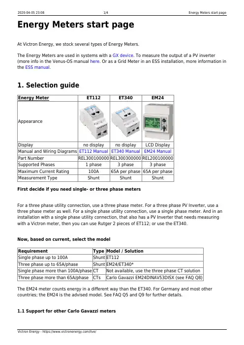
Energy Meters start pageAt Victron Energy, we stock several types of Energy Meters.The Energy Meters are used in systems with a GX device. To measure the output of a PV inverter (more info in the Venus-OS manual here. Or as a Grid Meter in an ESS installation, more information in the ESS manual.1. Selection guideEnergy Meter ET112ET340EM24AppearanceDisplay no display no display LCD DisplayManual and Wiring Diagrams ET112 Manual ET340 Manual EM24 ManualPart Number REL300100000REL300300000REL200100000Supported Phases 1 phase 3 phase 3 phaseMaximum Current Rating100A65A per phase65A per phaseMeasurement Type Shunt Shunt ShuntFirst decide if you need single- or three phase metersFor a three phase utility connection, use a three phase meter. For a three phase PV Inverter, use a three phase meter as well. For a single phase utility connection, use a single phase meter. And in an installation with a single phase utility connection, that also has a PV Inverter that needs measuring with a Victron meter, then you can use Rutger 2 pieces of ET112; or use the ET340.Now, based on current, select the modelRequirement Type Model / SolutionSingle phase up to 100A Shunt ET112Three phase up to 65A/phase Shunt EM24/ET340*Single phase more than 100A/phase CT Not available, use the three phase CT solutionThree phase more than 65A/phase CTs Carlo Gavazzi EM24DINAV53DISX (see FAQ Q8)The EM24 meter counts energy in a different way than the ET340. For Germany and most other countries; the EM24 is the advised model. See FAQ Q5 and Q9 for further details.1.1 Support for other Carlo Gavazzi metersBesides above listed meters, there are many more meters available from Carlo Gavazzi. Use this list to see which ones are compatible.Type Support RemarksEM111Supported Compatible with ET112.ET111Supported Compatible with ET112.EM112Supported Compatible with ET112.ET340Supported None.EM340Not supported does not report exported energy per phase (unlike the ET340)EM21 72D Not supported does not report exported energy,com protocol not compatible with supported grid metersEM271Not supported does not report exported energy,com protocol not compatible with supported grid meters3. FAQQ1: Can I combine three ET112s for a three phase system?No. Use a real three-phase meter.Q2: Can I use other meters, for example from other brands?No.Q3: I already have a Fronius SmartGrid meter, can I use that?No.Q5: What are the differences between the various three phase meters?EM24 - REL200100000 - Carlo Gavazzi EM24DINAV93XISXET112 - REL300100000 - Carlo Gavazzi ET112-DIN.AV01.X.S1.XET340 - REL300300000 - Carlo Gavazzi ET340-DIN.AV23.X.S1.XDifferences:The ET meters don't have a front selector that the installer needs to put in a different setting than it comes out of the box: easier, less mistakes to be made.The ET meters have no display. The only thing they have is an LED, which blinks in case ofactive communication.The new meters have 2 RJ45 sockets for the Modbus RS485 connection. But they are not used.Note the possible confusion because of yet another RJ-45 socket in the Victron world though.Don't mix that with VE.Bus, VE.Can or . Besides the RJ-45 sockets, the meters still also have screw terminals access below the sockets for the RS485 wiring, which is how we advise to connect a meter to the RS485 to USB interface and then CCGX.Since there is no display, the Modbus address can no longer be changed on the meter.Combining multiple of those meters on one RS485 network is therefore not supported byVictron. You are advised to use multiple RS485 to USB interfaces.Three-phase new meter only (ET340):Measuring Energy from single phase PV Inverter on the second phase of the new meter, ET340, actually works. Where-as with the old meter, the EM24, only the Power Metering (Watts) works.The Energy Metering (kWh) for a single phase PV Inverter on the second phase of the EM24does not work. See Q9 for the details.Q6: Will you keep shipping both 3 phase meters? (ET340 & EM24)Yes. There are still situations suitable for each. See Q9.Q7: Can I buy those meters directly from Carlo Gavazzi instead of from you?Yes. That is also why we make no secret of the CG part numbers.Q8: I want to use Current Transformers (CTs), is that possible?Yes. You can buy the CG EM24DINAV53DISX directly from Carlo Gavazzi or one of their distributors. Even though Victron does not stock that type of meter, we do support it in our software.The EM24DINAV53DISX is the solution for three-phase systems that go over 65A per phase.Q9: What’s the difference between ET340 and EM24 in 3 phase systems?These meters have a different way of calculating the total of energy imported and exported.In the ET340 - the energy imported and exported is counted at each individual phase and then the Total is provided from the sum of those values.In the EM24 - the energy imported and exported is counted as a total power, with net differential readings from each phase cancelling each other out.Which meter is best to use with depend on your countries own metering configuration. It is most common in Australia and Germany for example to only be billed for the total in a 3 phase system. So it is more accurate to use an EM24 to match the billing.So if you are exporting from one phase, and importing from another phase after the energy meter, but before the billing meter then you will not be charged for this, and the meter should not count it as an import and an export.This is also how Victron’s phase compensation feature works, to make the most of the cost savings for an ESS system when there is a differential in generation and load across different phases.Q10: Can I use an isolated USB-RS485 interface?Yes. The interfaces we sell are non isolated; suitable for most use cases.In case an isolated one is needed; purchase it dirsctly from Hjelmslund Electronics.USB485-STIXL : Isolated USB to RS485 converterDISQUSView the discussion thread.。
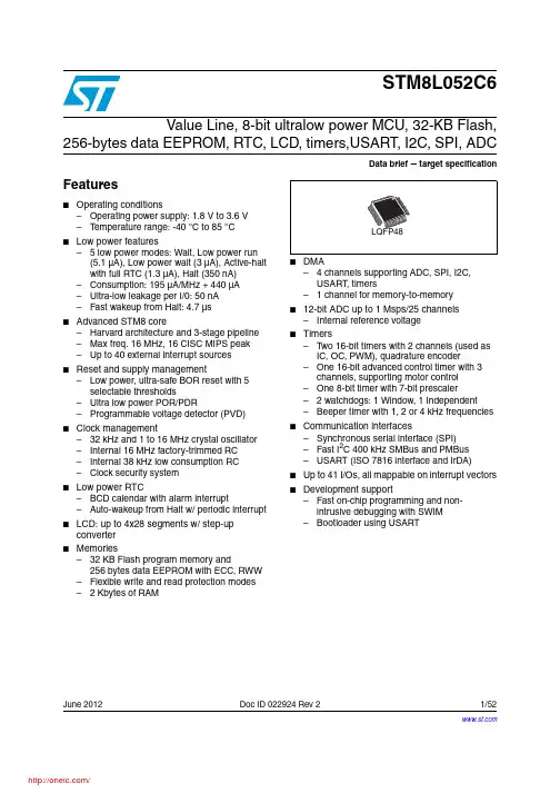
June 2012Doc ID 022924 Rev 21/52STM8L052C6Value Line, 8-bit ultralow power MCU, 32-KB Flash,256-bytes data EEPROM, RTC, LCD, timers,USART, I2C, SPI, ADCData brief target specificationFeatures■Operating conditions–Operating power supply: 1.8 V to 3.6 V –T emperature range: -40 °C to 85 °C ■Low power features– 5 low power modes: Wait, Low power run (5.1µA), Low power wait (3µA), Active-halt with full RTC (1.3µA), Halt (350nA)–Consumption: 195 µA/MHz + 440 µA –Ultra-low leakage per I/0: 50 nA –Fast wakeup from Halt: 4.7 µs■Advanced STM8 core–Harvard architecture and 3-stage pipeline –Max freq. 16 MHz, 16 CISC MIPS peak –Up to 40 external interrupt sources ■Reset and supply management–Low power, ultra-safe BOR reset with 5 selectable thresholds–Ultra low power POR/PDR–Programmable voltage detector (PVD)■Clock management–32 kHz and 1 to 16 MHz crystal oscillator –Internal 16 MHz factory-trimmed RC –Internal 38 kHz low consumption RC –Clock security system■Low power RTC–BCD calendar with alarm interrupt–Auto-wakeup from Halt w/ periodic interrupt ■LCD: up to 4x28 segments w/ step-up converter■Memories–32 KB Flash program memory and256bytes data EEPROM with ECC, RWW –Flexible write and read protection modes – 2 Kbytes of RAM■– 4 channels supporting ADC, SPI, I2C, USART , timers– 1 channel for memory-to-memory ■12-bit ADC up to 1 Msps/25 channels –Internal reference voltage■Timers–T wo 16-bit timers with 2 channels (used as IC, OC, PWM), quadrature encoder–One 16-bit advanced control timer with 3 channels, supporting motor control –One 8-bit timer with 7-bit prescaler– 2 watchdogs: 1 Window, 1 Independent –Beeper timer with 1, 2 or 4 kHz frequencies ■Communication interfaces–Synchronous serial interface (SPI)–Fast I2C 400 kHz SMBus and PMBus –USART (ISO 7816 interface and IrDA)■Up to 41 I/Os, all mappable on interrupt vectors ■Development support–Fast on-chip programming and non- intrusive debugging with SWIM –Bootloader using USARTContents STM8L052C6Contents1Introduction . . . . . . . . . . . . . . . . . . . . . . . . . . . . . . . . . . . . . . . . . . . . . . . . 62Description . . . . . . . . . . . . . . . . . . . . . . . . . . . . . . . . . . . . . . . . . . . . . . . . . 72.1Device overview . . . . . . . . . . . . . . . . . . . . . . . . . . . . . . . . . . . . . . . . . . . . . 82.2Ultra low power continuum . . . . . . . . . . . . . . . . . . . . . . . . . . . . . . . . . . . . . 93Functional overview . . . . . . . . . . . . . . . . . . . . . . . . . . . . . . . . . . . . . . . . 103.1Low power modes . . . . . . . . . . . . . . . . . . . . . . . . . . . . . . . . . . . . . . . . . . 113.2Central processing unit STM8 . . . . . . . . . . . . . . . . . . . . . . . . . . . . . . . . . 123.2.1Advanced STM8 Core . . . . . . . . . . . . . . . . . . . . . . . . . . . . . . . . . . . . . . 123.2.2Interrupt controller . . . . . . . . . . . . . . . . . . . . . . . . . . . . . . . . . . . . . . . . . 123.3Reset and supply management . . . . . . . . . . . . . . . . . . . . . . . . . . . . . . . . 133.3.1Power supply scheme . . . . . . . . . . . . . . . . . . . . . . . . . . . . . . . . . . . . . . 133.3.2Power supply supervisor . . . . . . . . . . . . . . . . . . . . . . . . . . . . . . . . . . . . 133.3.3Voltage regulator . . . . . . . . . . . . . . . . . . . . . . . . . . . . . . . . . . . . . . . . . . 133.4Clock management . . . . . . . . . . . . . . . . . . . . . . . . . . . . . . . . . . . . . . . . . 143.5Low power real-time clock . . . . . . . . . . . . . . . . . . . . . . . . . . . . . . . . . . . . 153.6LCD (Liquid crystal display) . . . . . . . . . . . . . . . . . . . . . . . . . . . . . . . . . . . 163.7Memories . . . . . . . . . . . . . . . . . . . . . . . . . . . . . . . . . . . . . . . . . . . . . . . . . 163.8DMA . . . . . . . . . . . . . . . . . . . . . . . . . . . . . . . . . . . . . . . . . . . . . . . . . . . . . 163.9Analog-to-digital converter . . . . . . . . . . . . . . . . . . . . . . . . . . . . . . . . . . . . 173.10System configuration controller and routing interface . . . . . . . . . . . . . . . 173.11Timers . . . . . . . . . . . . . . . . . . . . . . . . . . . . . . . . . . . . . . . . . . . . . . . . . . . 173.11.1TIM1 - 16-bit advanced control timer . . . . . . . . . . . . . . . . . . . . . . . . . . . 183.11.216-bit general purpose timers . . . . . . . . . . . . . . . . . . . . . . . . . . . . . . . . 183.11.38-bit basic timer . . . . . . . . . . . . . . . . . . . . . . . . . . . . . . . . . . . . . . . . . . . 183.12Watchdog timers . . . . . . . . . . . . . . . . . . . . . . . . . . . . . . . . . . . . . . . . . . . 183.12.1Window watchdog timer . . . . . . . . . . . . . . . . . . . . . . . . . . . . . . . . . . . . . 183.12.2Independent watchdog timer . . . . . . . . . . . . . . . . . . . . . . . . . . . . . . . . . 183.13Beeper . . . . . . . . . . . . . . . . . . . . . . . . . . . . . . . . . . . . . . . . . . . . . . . . . . . 193.14Communication interfaces . . . . . . . . . . . . . . . . . . . . . . . . . . . . . . . . . . . . 193.14.1SPI . . . . . . . . . . . . . . . . . . . . . . . . . . . . . . . . . . . . . . . . . . . . . . . . . . . . . 193.14.2I²C . . . . . . . . . . . . . . . . . . . . . . . . . . . . . . . . . . . . . . . . . . . . . . . . . . . . . 19 2/52Doc ID 022924 Rev 2STM8L052C6Contents3.14.3USART . . . . . . . . . . . . . . . . . . . . . . . . . . . . . . . . . . . . . . . . . . . . . . . . . . 193.15Infrared (IR) interface . . . . . . . . . . . . . . . . . . . . . . . . . . . . . . . . . . . . . . . . 203.16Development support . . . . . . . . . . . . . . . . . . . . . . . . . . . . . . . . . . . . . . . . 204Pin description . . . . . . . . . . . . . . . . . . . . . . . . . . . . . . . . . . . . . . . . . . . . 214.1System configuration options . . . . . . . . . . . . . . . . . . . . . . . . . . . . . . . . . . 265Memory and register map . . . . . . . . . . . . . . . . . . . . . . . . . . . . . . . . . . . 275.1Memory mapping . . . . . . . . . . . . . . . . . . . . . . . . . . . . . . . . . . . . . . . . . . . 275.2Register map . . . . . . . . . . . . . . . . . . . . . . . . . . . . . . . . . . . . . . . . . . . . . . 28 6Interrupt vector mapping . . . . . . . . . . . . . . . . . . . . . . . . . . . . . . . . . . . . 457Package characteristics . . . . . . . . . . . . . . . . . . . . . . . . . . . . . . . . . . . . . 477.1ECOP ACK . . . . . . . . . . . . . . . . . . . . . . . . . . . . . . . . . . . . . . . . . . . . . . . . 477.2Package mechanical data . . . . . . . . . . . . . . . . . . . . . . . . . . . . . . . . . . . . 487.2.148-pin low profile quad flat 7x7mm package (LQFP48) . . . . . . . . . . . . . 48 8Device ordering information . . . . . . . . . . . . . . . . . . . . . . . . . . . . . . . . . . 50 9Revision history . . . . . . . . . . . . . . . . . . . . . . . . . . . . . . . . . . . . . . . . . . . 51Doc ID 022924 Rev 23/52List of tables STM8L052C6 List of tablesTable 1.Medium density value line STM8L05xxx low power device features and peripheral counts 8 Table 2.Timer feature comparison. . . . . . . . . . . . . . . . . . . . . . . . . . . . . . . . . . . . . . . . . . . . . . . . . . 17 Table 3.Legend/abbreviation for Table4. . . . . . . . . . . . . . . . . . . . . . . . . . . . . . . . . . . . . . . . . . . . . 22 Table 4.Medium density value line STM8L05xxx pin description . . . . . . . . . . . . . . . . . . . . . . . . . . 22 Table 5.Flash and RAM boundary addresses. . . . . . . . . . . . . . . . . . . . . . . . . . . . . . . . . . . . . . . . . 28 Table 6.I/O port hardware register map. . . . . . . . . . . . . . . . . . . . . . . . . . . . . . . . . . . . . . . . . . . . . . 28 Table 7.General hardware register map . . . . . . . . . . . . . . . . . . . . . . . . . . . . . . . . . . . . . . . . . . . . . 29 Table 8.CPU/SWIM/debug module/interrupt controller registers. . . . . . . . . . . . . . . . . . . . . . . . . . . 43 Table 9.Interrupt mapping . . . . . . . . . . . . . . . . . . . . . . . . . . . . . . . . . . . . . . . . . . . . . . . . . . . . . . . . 45 Table 10.LQFP48 48-pin low profile quad flat package, mechanical data. . . . . . . . . . . . . . . . . . . . . 48 Table 11.Document revision history . . . . . . . . . . . . . . . . . . . . . . . . . . . . . . . . . . . . . . . . . . . . . . . . . 51 4/52Doc ID 022924 Rev 2STM8L052C6List of figures List of figuresFigure 1.Medium density value line STM8L05xxx device block diagram. . . . . . . . . . . . . . . . . . . . 10 Figure 2.Medium density value line STM8L05xxx clock tree diagram . . . . . . . . . . . . . . . . . . . . . . 15 Figure 3.STM8L052C6 48-pin LQFP48 package pinout (with LCD) . . . . . . . . . . . . . . . . . . . . . . . . 21 Figure 4.Memory map . . . . . . . . . . . . . . . . . . . . . . . . . . . . . . . . . . . . . . . . . . . . . . . . . . . . . . . . . . 27 Figure 5.LQFP48 48-pin low profile quad flat package outline. . . . . . . . . . . . . . . . . . . . . . . . . . . . . 48 Figure 6.LQFP48 recommended footprint . . . . . . . . . . . . . . . . . . . . . . . . . . . . . . . . . . . . . . . . . . . . 49 Figure 7.Medium density value line STM8L05xxx ordering information scheme . . . . . . . . . . . . . . . 50Doc ID 022924 Rev 25/52Introduction STM8L052C66/52Doc ID 022924 Rev 21 I ntroductionThis document describes the features, pinout, mechanical data and ordering information ofthe medium density value line STM8L052C6 microcontroller with 32-Kbyte Flash memory density. For further details on the whole STMicroelectronics medium density family please refer to Section 2.2: Ultra low power continuum .For detailed information on device operation and registers, refer to the reference manual (RM0031).For information on to the Flash program memory and data EEPROM, refer to the programming manual (PM0054).For information on the debug module and SWIM (single wire interface module), refer to the STM8 SWIM communication protocol and debug module user manual (UM0470).For information on the STM8 core, refer to the STM8 CPU programming manual (PM0044).Medium density value line devices provide the following benefits:●Integrated system–32 Kbytes of medium density embedded Flash program memory –256 bytes of data EEPROM – 2 Kbytes of RAM –Internal high speed and low-power low speed RC –Embedded reset ●Ultra low power consumption–195 µA/MHZ + 440 µA (consumption)–0.9 µA with LSI in Active-halt mode –Clock gated system and optimized power management –Capability to execute from RAM for Low power wait mode and low power run mode ●Advanced features–Up to 16 MIPS at 16 MHz CPU clock frequency –Direct memory access (DMA) for memory-to-memory or peripheral-to-memoryaccess● Short development cycles–Application scalability across a common family product architecture withcompatible pinout, memory map and modular peripherals –Wide choice of development tools Refer to T able 1: Medium density value line STM8L05xxx low power device features and peripheral counts and Section 3: Functional overview for an overview of the complete range of peripherals proposed in this family.Figure 1 shows the block diagram of the medium density value line STM8L05xxx family.STM8L052C6Description 2 DescriptionThe medium density value line STM8L05xxx devices are members of the STM8L ultra lowpower 8-bit family.The value line STM8L05xxx ultra low power family features the enhanced STM8 CPU coreproviding increased processing power (up to 16 MIPS at 16 MHz) while maintaining theadvantages of a CISC architecture with improved code density, a 24-bit linear addressingspace and an optimized architecture for low power operations.The family includes an integrated debug module with a hardware interface (SWIM) whichallows non-intrusive In-application debugging and ultra-fast Flash programming.Medium density value line STM8L05xxx microcontrollers feature embedded data EEPROMand low-power, low-voltage, single-supply program Flash memory.All devices offer 12-bit ADC, real-time clock, 16-bit timers, one 8-bit timer as well asstandard communication interface such as SPI, I2C, USART and 4x28-segment LCD. The4x 28-segment LCD is available on the medium density value line STM8L05xxx.The STM8L05xxx family operates from 1.8 V to 3.6 V and is available in the -40 to +85 °Ctemperature range.The modular design of the peripheral set allows the same peripherals to be found in differentST microcontroller families including 32-bit families. This makes any transition to a differentfamily very easy, and simplified even more by the use of a common set of developmenttools.All value line STM8L ultra low power products are based on the same architecture with thesame memory mapping and a coherent pinout.Doc ID 022924 Rev 27/52Description STM8L052C68/52Doc ID 022924 Rev 22.1 Device overviewTable 1.Medium density value line STM8L05xxx low power device features andperipheral countsFeaturesSTM8L052C6Flash (Kbytes)32Data EEPROM (bytes)256RAM (Kbytes)2LCD4x28Timers Basic1 (8-bit)General purpose 2(16-bit)Advanced control 1 (16-bit)CommunicationinterfacesSPI1I2C1USART 1GPIOs41(1)1.The number of GPIOs given in this table includes the NRST/PA1 pin but the application can use theNRST/PA1 pin as general purpose output only (PA1).12-bit synchronized ADC (number of channels) 1 (25)Others RTC, window watchdog, independent watchdog,16-MHz and 38-kHz internal RC,1- to 16-MHz and 32-kHz external oscillatorCPU frequency 16 MHz Operating voltage 1.8 V to 3.6 V Operating temperature -40 to +85 °C PackageLQFP48STM8L052C6DescriptionDoc ID 022924 Rev 29/522.2 Ultra low power continuumThe ultra low power value line STM8L05xxx and STM8L15xxx are fully pin-to-pin, software and feature compatible. Besides the full compatibility within the STM8L family, the devices are part of STMicroelectronics microcontrollers ultra low power strategy which also includes STM8L101xx and STM32L15xxx. The STM8L and STM32L families allow a continuum of performance, peripherals, system architecture, and features.They are all based on STMicroelectronics 0.13µm ultra-low leakage process.Note:1The STM8L05xxx is pin-to-pin compatible with STM8L101xx devices.2The STM32L family is pin-to-pin compatible with the general purpose STM32F family. Please refer to STM32L15x documentation for more information on these devices.PerformanceAll families incorporate highly energy-efficient cores with both Harvard architecture and pipelined execution: advanced STM8 core for STM8L families and ARM Cortex™-M3 core for STM32L family. In addition specific care for the design architecture has been taken to optimize the mA/DMIPS and mA/MHz ratios.This allows the ultra low power performance to range from 5 up to 33.3DMIPs.Shared peripheralsSTM8L05x, STM8L15x and STM32L15xx share identical peripherals which ensure a very easy migration from one family to another:●Analog peripheral: ADC1●Digital peripherals: RTC and some communication interfacesCommon system strategyTo offer flexibility and optimize performance, the STM8L and STM32L devices use a common architecture:●Same power supply range from 1.8 to 3.6V●Architecture optimized to reach ultra-low consumption both in low power modes and Run mode●Fast startup strategy from low power modes ●Flexible system clock●Ultra-safe reset: same reset strategy for both STM8L and STM32L including power-on reset, power-down reset, brownout reset and programmable voltage detectorFeaturesST ultra low power continuum also lies in feature compatibility:●More than 10 packages with pin count from 20 to 100 pins and size down to 3 x 3mm ●Memory density ranging from 4 to 128 KbytesFunctional overview STM8L052C610/52Doc ID 022924 Rev 23 Functional overviewFigure 1.Medium density value line STM8L05xxx device block diagram1.Legend :ADC: Analog-to-digital converter BOR: Brownout resetDMA: Direct memory accessI²C: Inter-integrated circuit multimaster interface LCD: Liquid crystal displayPOR/PDR: Power on reset / power down reset RTC: Real-time clockSPI: Serial peripheral interfaceSWIM: Single wire interface moduleUSART: Universal synchronous asynchronous receiver transmitter WWDG: Window watchdog IWDG: independent watchdog16 MHz internal RC Clock Clocks A d d r e s s , c o n t r o l a n d d a t a b u s e sDebug moduleSPI132 Kbytes Interrupt controller2 Kbytes RAMto core and peripheralsIWDG (38 kHz clock)(SWIM)Port A Port B Port C I²C1USART1PowerVOLT. REG.Port F 1-16 MHz oscillator 32 kHz oscillator 38 kHz internal RC LCD driver 4x28WWDGSTM8 Corecontroller and CSS256 bytes Port D Port E BeeperRTC memoryprogram data EEPROM @V DDV DD18V DD1 =1.8 VV SS1SWIMSCL, SDA,MOSI, MISO, SCK, NSS RX, TX, CKADC1_INxV DDA V SSASMB @V DDA /V SSA12-bit ADC1V REF+V REF-3.6 V NRSTPA[7:0]PB[7:0]PC[7:0]PD[7:0]PE[7:0]PF0BEEPALARM, CALIBSEGx, COMxPOR/PDR OSC_IN,OSC_OUT OSC32_IN,OSC32_OUTto BOR PVDPVD_INRESET DMA18-bit Timer 416-bit Timer 3 16-bit Timer 2 16-bit Timer 1 (4 channels)2 channels 2 channels3 channelsV LCD = 2.5 V 3.6 VtoLCD boosterInternal referencevoltageVREFINT outInfrared interface IR_TIM分销商库存信息: STMSTM8L052C6T6。
![T6产品说明书[1]](https://uimg.taocdn.com/6d2f0b0deff9aef8941e0626.webp)
能源之星新标准RLF_41Draft1-Chinese 目录第一章:定义第二章:资格认证的产品第三章:具有资格认证产品的能效规格第四章:赋予资格过程,测试设备,标准和文件第五章:附加的质量保证要求第六章:生效日期第七章:将来版本的校订附件:表1:户内灯具表1A:对户内嵌入式花样筒灯的额外要求表2A:户外灯具:符合有效光源的要求表2B:户外灯具:符合减少工作时间的要求表3:GU-24一体化灯能源之星标准下面就是住宅灯具的能源之星生产规格(4.1版本)。
如果制造商想在一种产品上贴能源之星的标贴就必须符合相应的标准。
住宅灯具能源之星的目的是让消费者从传统理念上的白炽灯具转变为高质量的荧光灯具或者其他的能效技术,包括针对户外灯具的运动传感器和日光传感器。
1)定义:下面是灯具和其他能源之星相关术语的简要定义:A.ALA:美国照明学会。
B.ANSI:美国国家标准协会。
C.APLAC:亚太地区试验室鉴定协会(NALAPMRA签署)。
D.自动日光关闭:一种能在白天自动禁止灯具开关开启的光电装置。
E.镇流器:一种与电子射灯一起使用的装置,用以获得开启和运作时电路的一些基本参数(电压、电流和波形)。
F.镇流器的频率:镇流器使灯泡运作时产生的频率,单位是赫兹(Hz)或千赫兹(KHz)。
G.CIE:德国国际电工委员会。
H.显色:灯发出的光其光谱特性会使被照射的物体表面呈现一种颜色,叫做显色。
显色指数可用0~100等级表示。
显色指数是由物体在测试光照下的三色光谱值与在参照或标准光照下的三色光谱值相比较而决定的。
检索条目和标准可参照CIE公布的13.3号文件。
I.紧凑型荧光灯:一种附带插座式灯座的单灯座节能荧光灯,包括有多管型,U字型,螺旋型和环形灯管这几个种类。
J.相关色温(CCT):灯的实际颜色叫色温,是由三色光谱值(颜色坐标系)参照IESNALM-16标准所决定的。
对于颜色坐标系中靠近黑色的地方使用相关色温,用开氏温标(K)表示。
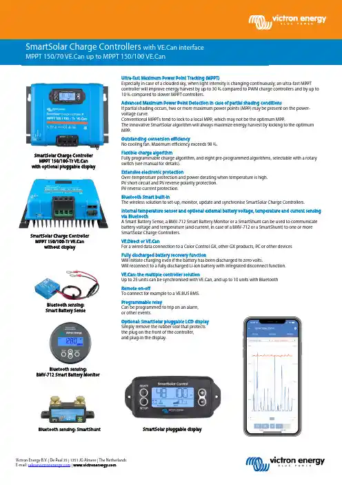
Victron Energy B.V. | De Paal 35 | 1351 JG Almere | The Netherlands E-mail: *********************** | Ultra-fast Maximum Power Point Tracking (MPPT)Especially in case of a clouded sky, when light intensity is changing continuously, an ultra-fast MPPT controller will improve energy harvest by up to 30 % compared to PWM charge controllers and by up to 10 % compared to slower MPPT controllers.Advanced Maximum Power Point Detection in case of partial shading conditionsIf partial shading occurs, two or more maximum power points (MPP) may be present on the power-voltage curve.Conventional MPPTs tend to lock to a local MPP, which may not be the optimum MPP.The innovative SmartSolar algorithm will always maximize energy harvest by locking to the optimum MPP.Outstanding conversion efficiencyNo cooling fan. Maximum efficiency exceeds 98 %.Flexible charge algorithmFully programmable charge algorithm, and eight pre-programmed algorithms, selectable with a rotary switch (see manual for details).Extensive electronic protectionOver-temperature protection and power derating when temperature is high. PV short circuit and PV reverse polarity protection. PV reverse current protection.Bluetooth Smart built-inThe wireless solution to set-up, monitor, update and synchronise SmartSolar Charge Controllers.Internal temperature sensor and optional external battery voltage, temperature and current sensing via BluetoothA Smart Battery Sense, a BMV-712 Smart Battery Monitor or a SmartShunt can be used to communicate battery voltage and temperature (and current, in case of a BMV-712 or a SmartShunt) to one or more SmartSolar Charge Controllers.VE.Direct or VE.CanFor a wired data connection to a Color Control GX, other GX products, PC or other devicesFully discharged battery recovery functionWill initiate charging even if the battery has been discharged to zero volts.Will reconnect to a fully discharged Li-ion battery with integrated disconnect function.VE.Can: the multiple controller solutionUp to 25 units can be synchronised with VE.Can, and up to 10 units with BluetoothRemote on-offTo connect for example to a VE.BUS BMS.Programmable relayCan be programmed to trip on an alarm, or other events.Optional: SmartSolar pluggable LCD display Simply remove the rubber seal that protects the plug on the front of the controller, and plug-in the display.SmartSolar Charge Controller MPPT 150/100-Tr VE.Can with optional pluggable displayVictron Energy B.V. | De Paal 35 | 1351 JG Almere | The NetherlandsE-mail: *********************** | Battery voltage12/24/48 V Auto Select (36 V: manual)Rated charge current70 A 85 A 100 A Nominal PV power, 12 V 1a,b) 1000 W 1200 W 1450 W Nominal PV power, 24 V 1a,b) 2000 W 2400 W 2900 W Nominal PV power, 36 V 1a,b) 3000 W 3600 W 4350 W Nominal PV power, 48 V 1a,b) 4000 W 4900 W 5800 WMax. PV short circuit current 2) 50 A (max 30 A per MC4 conn.) 70 A (max 30 A per MC4 conn.)Maximum PV open circuit voltage 150 V absolute maximum coldest conditions 145 V start-up and operating maximumMaximum efficiency 98 %Self-consumptionLess than 35 mA @ 12 V / 20 mA @ 48 V Charge voltage 'absorption' Default setting: 14,4 / 28,8 / 43,2 / 57,6 V(adjustable with: rotary switch, display, VE.Direct or Bluetooth)Charge voltage 'float' Default setting: 13,8 / 27,6 / 41,4 / 55,2 V(adjustable: rotary switch, display, VE.Direct or Bluetooth) Charge voltage 'equalization' Default setting: 16,2 V / 32,4 V / 48,6 V / 64,8 V (adjustable)Charge algorithmmulti-stage adaptive (eight preprogrammed algorithms) or user defined algorithmTemperature compensation -16 mV / -32 mV / -64 mV / °CProtectionPV reverse polarity / Output short circuit / Over temperatureOperating temperature -30 to +60 °C (full rated output up to 40 °C)Humidity95 %, non-condensingMaximum altitude5000m (full rated output up to 2000m)Environmental condition Indoor, unconditionedPollution degree PD3Data communication VE.Can, VE.Direct and BluetoothRemote on/offYes (2 pole connector)Programmable relay DPST AC rating: 240 VAC / 4 A DC rating: 4 A up to 35 VDC, 1 A up to 60 VDCParallel operation Yes, parallel synchronised operation with VE.Can (max. 25 units) or Bluetooth (max. 10 units)Colour Blue (RAL 5012)PV terminals 3) 35 mm² / AWG2 (Tr models)Two pairs of MC4 connectors(MC4 models)35 mm² / AWG2 (Tr models)Three pairs of MC4 connectors (MC4 models)Battery terminals 35mm² / AWG2Protection category IP43 (electronic components), IP22 (connection area)Weight3 kg 4,5kgDimensions (h x w x d) in mm Tr models: 185 x 250 x 95 mm MC4 models: 215x 250 x 95 mm Tr models: 216 x 295 x 103 MC4 models: 246 x 295 x 103SafetyEN/IEC 62109-1, UL 1741, CSA C22.2Data storedBattery voltage,current and temperature, as well as load output current, PV voltage and PV current.Number of days trends data is stored461a) If more PV power is connected, the controller will limit input power.1b) The PV voltage must exceed Vbat + 5 V for the controller to start. Thereafter the minimum PV voltage is Vbat + 1 V. 2) A PV array with a higher short circuit current may damage the controller.3) MC4 models: several splitter pairs may be needed to parallel the strings of solar panelsMaximum current per MC4 connector: 30 A (the MC4 connectors are parallel connected to one MPPT tracker)With VE.Can or Bluetooth up to 25 respectively up to 10 Charge Controllers can be daisy-chained forsynchronous charging and connected to a Color Control GX or other GX device.Each Controller can be monitored individually, for example on a Color Control GX and on the VRMwebsite (VE.Can) or on a smartphone or iPad (Bluetooth)。
能源之星Table of Contents内容Section 1: Definitions 2第一部分:定义2Section 2: Qualifying Products 4第二部分:合格产品Section 3: Energy Efficiency Specifications for Qualifying Products 4第三部分:合格产品的能效规格Table 1: Indoor Fixtures 4表1:室内灯具Table 1A: Additional Requirements for Indoor Recessed Downlight Retrofit Kits 8表1A:嵌入式室内筒灯系列的额外要求Table 2A: Outdoor Fixtures: Compliance Through Efficient Light Source 10表2A:室外灯具:适合高效的灯源Table 2B: Outdoor Fixtures: Compliance Through Reduced Operating Time 12表2B:室外灯具:光感型Section 4: Qualification Process, Testing Facilities, Standards & Documentation 13第四部分:检验过程,测试设施,标准&文本资料Table 3: Reference Standards and Required Documentation 15表3:参考标准&资料Section 5: Additional Quality Assurance Requirements 28第五部分:额外的质量保证要求Section 6: Effective Date 29第六部分:有效期Section 7: Future Specification Revisions 29第七部分:预计规格一览表ENERGY STAR_ Program Requirements forResidential Light Fixtures民用灯具能源之星计划Eligibility Criteria – Version 4.0标准-版本4.0Below is the product specification (Version 4.0) for ENERGY STAR qualified residential light fixtures. A product must meet all of the identified criteria if it is to be labeled as ENERGY STAR by its manufacturer.以下是能源之星合格民用灯具产品规格(4.0版本)。
页,共30 页录第一部分:"能源之星(Energy Star)"及其它术语定义――――――――――――第2-4页第二部分:产品认证资格―――――――――――――――――――――――――第5页第三部分:产品认证能效规范标准―――――――――――――――――――――第5页表1:室内灯具―――――――――――――――――――――――― 第6-9页表1A:室内筒灯升级套件其他要求――――――――――――――― 第10页表2A:户外灯具-藉由使用高效能光源――――――――――――――第11-12页表2B:户外灯具-藉由降低使用时间――――――――――――――第13页第四部分:认证程序/适用的文件资料/参照标准和必须文件―――――――――――第14-15页表3:参照标准和必备文件资料――――――――――――――――――第16-27页第五部分:产品质量保证其它要求――――――――――――――――――――――第28-29页第六部分:生效日期――――――――――――――――――――――――――――第29-30页第七部分:规范要求的未来修订―――――――――――――――――――――――第30页能源之星-居家照明灯具的规范要求4.0版2 页,共30 页什麼是"能源之星(Energy Star)"能源之星(Energy Star)是美国政府推行的一个透过能源节约及有效利用能源以帮助企业及个人居家达到保护地球环境的计划.到目前为止,成效已很显著.仅仅是在2004年,透过"能源之星(Energy Star)"的协助,美国所节省的能源足足可以供应二千四百万住家的电力所需,且有效地降低了相当於二千万辆汽车所排放废气的温室效应,这部分也省了大约一百亿美金.美国环保署(EPA)提供了一套创新的能源效益评比系统.目前,在全美已有21,000栋商业大楼采用此系统来做大楼的能源管理.对於执行效果良好的企业或大楼,美国环保署(EPA)会颁发"能源之星(Energy Star)"的标章.如下为符合能源之星(Energy Star)的居家照明灯具产品的安规要求.如果生产厂商们预将其生产的产品贴标"Energy Star",则必须符合所有判定标准.能源之星(Energy Star)-居家照明灯具设定标准的主要目的是鼓励使用传统白炽灯的用户改为使用高质量荧光灯或其它节能科技,包括用於户外灯具的移动感应器和日光感应器.如下所述为与"能源之星(Energy Star)"相关联的灯具及其它术语的简骇定义:A. ALA(American Lighting Association):美国照明协会B. ANSI(American National Standards Institute): 美国国家标准协会C. APLAC(Asia Pacific Laboratory Accreditation Cooperation:亚太实验室签定协会D. 自动日光切断装置(Automatic Daylight Shutoff):在白天时段里,可以自动控制灯具运行的一种光电池装置.E. 镇流器(Ballast):是用来控制放电光源在开启和工作运行时所需的电路条件(电压,电流和波形)的一种装置. F. 镇流器频率(Ballast Frequency):镇流器运行光源的频率的测量单位是赫兹(Hertz/Hz)或千赫兹(Kilohertz/KHz).G. CIE(Commission international of Illumination):国际照明委员会能源之星-居家照明灯具的规范要求4.0版3 页,共30 页H. 演色性(Color Rendering):光源照射物体的颜色性质与光源所释放出的光在光谱中的表现效果是相得一章的.演色指数的测量值是0-100.演色性是根据照明测试时,物体在光谱中所表现出来的三基色的对比值以及国际照明委员会(CIE)No.13.3中所推荐的照明对照标准来定义的.I. 紧凑型荧光灯(Compact Fluorescent Lamp):是指带有插拔单灯头的荧光灯,包括多管型,多回管型,螺旋型以及圆型.J. 色温(Correlated Color Temperature / CCT):是指光源的真正颜色.色温是根据IESNA LM-16中所推荐的光谱中物体三基色值(颜色坐标) 来定义的.靠近黑体附近的颜色坐标,其物体相关色温是用"Kelvin(K)"来表示的.K. 电子镇流器(Electronic Ballast):它是通过使用半导体元件来增加荧光灯的工作频率.因为荧光灯系统效率是靠增加高频来实现的.L. IEC(International Electrotechnical Commission): 国际电工委员会M. IESNA(Illuminating Engineering Society of North America): 北美照明工程协会N. ILAC(International Laboratory Accreditation Cooperation):国际实验室签定协会O. 输入功率(Input Power):是指灯具在工作时,其所有光源及镇流器的实际消耗总功率,以"Watts(W)"来表示.P. 光源(Lamp):是光源生产商的通用术语.从广义上来讲,此术语还可以用来指可见光谱中光的辐射源.Q. 光源镇流器技术平台(Lamp Ballast Platform):一个镇流器可以同时用来操作一支或多支光源.此独特的技术平台是由生产商自订的.附有相关镇流器和单支(数支)光源的型号以及镇流器可以操作光源的数量.R. 光源电流峰值因数(Lamp Current Crest Factor):对於60Hz工作周频来讲,是指光源最高电流同光源电流均方根的比值;对於高工作周频来讲, 当超过全线总电压周频估定值时,其调幅包线的光源最高电流与光源电流的均方根的比值. S. 灯头(Lampholder):灯具的一个组成元件,主要用来供给光源电源和固定光源的.T. 灯具(Lighting Fixture/Luminaire):是指一个完整的照明设备.包括一支或数支光源,镇流器(需用时)或带有自用镇流器装置的发光零部件,光源固定及光源保护部件,光源接线连接.4 页,共30 页U. 直管形荧光灯(Linear Fluorescent Lamp):是一种双端插入式灯头的荧光灯,包括直管形和U管形.V. 电感镇流器(Magnetic Ballast):是一种运用磁芯和铜线在线电压周频下工作的镇流器.W. MRA(Mutual Recognition Arrangement):互辨排列X. NACLA(National Cooperation for Laboratory Accreditation):国家实验室签定协会Y. NEMA(National Electrical Manufacturers Association): 国家电器生产商会Z. NFPA(National Fire Protection Association): 美国国家消防协会:负责开发美国国家电器使用法案.AA. NRTL(Nationally Recognized Testing Laboratory): 国家公认检测实验室:是美国职业安全与卫生条例管理局(OSHA)技术支持董事会的一部分.BB. NVLAP(National V oluntary Laboratory Accreditation Program):国家义务实验室签定规划CC. 光学组件(Optics):包括反光罩,遮光板,反光镜或透光罩.主要是用来控制灯具光分配以及外观形态的.DD. OSHA(Occupational Safety & Health Administration):职业安全与卫生条例管理局EE. 绞编花式电线(Pigtail Cable):是一种带有双端转接头的电线,主要是起转换两种接头的电流从而达到相互兼容的功用,也称为螺旋式转换器和插座转换器.FF. 功率因数(Power Factor):实际消耗功率与电源输入功率的比值(也就是指灯具总功率与输入的电压乘电流的比值). GG.筒灯升级套件(Recessed downlight retrofit kit):是指用於非直管形灯管灯具的专用改装套件,包括一支(或数支)光源,镇流器或自用式镇流器装置,光学反射器,边框,电源接线等等.其主要功用是可以将安装在绝缘(IC)或非绝缘(non-IC)天花板上的白炽灯或卤素筒灯转变为使用节能光源的密封筒灯灯具.II. 边框(Trim):是筒灯的一个组成部分,用来遮盖(密封或非密封式)天花板开孔处的毛边.此边框也许是分立式圆环,或者是与光学器件一体式设计(如,自折形反光罩).JJ. Underwriters Laboratories /UL: 美国安规5 页,共30 页2)产品认证资格要求:能源之星(Energy Star)居家照明灯具安规主要包括室内,户外灯具和筒灯升级套件.此安规要求主要适用於居家照明,如单户和多户式的普通住房或公寓住房,宿舍,公民或军队住房,助困房,汽车旅馆,大酒店和一些商业照明应用场所.电感镇流器除外:凡是使用电感镇流器的室内灯具都不符合"能源之星(Energy Star)4.0版"安规要求.但是使用高压放电灯(如金卤灯和高压钠灯)的户外灯具则例外,可以继续使用电感镇流器. 内置镇流器插拔式光源的容许范围:如果那些使用内置镇流器插拔式光源的室内和户外灯具符合所有应用要求(室内灯具-见图表1中1A,户外灯具-见图表2A或2B)就可以通过"能源之星(EnergyStar)"的认证.其应用要求包括:A. 光源平均额定寿命:等於或大於10,000小时;B. 在正常的工作条件下,放在灯具内的镇流器的表壳最高温度不能超过其生产商的所建议的最高温度值.C. 另外,用来驱动26W光源或较低线电压的灯座的镇流器必须符合美国环保署(EPA)和工业的设计标准.LED装饰用灯的暂时容许范围:美国环保署(EPA)鼓励消费者使用像LEDs这种新一代光源技术.LEDs光源可以用於居家照明灯具内的照明装饰用组件和吊扇灯用的套件,只要所用LEDs光源的总功率不超过5W, LEDs系统(LED和驱动器)平均光效至少每瓦20流明和符合适用标准中所列出的有关辅助光源的应用性能特点即可."LED厂商欲申请"能源之星(Energy Star)"认证,须提供下列资料给美国环保总署(EPA):A. LED灯具的总消耗功率B. 生产商保修书C. LED本身的技术资料:瓦特数,光效,光源寿命,颜色,光衰这只是使用LEDs光源的临时暂定标准.美国环保署(EPA)计划开发出更多的有关LEDs光源先进科技的全面规范,使之更加广泛地应用於居家照明中.3) 产品认证能效规范标准:只有在第二部分中所列出的产品符合下文的要求标准,这样才可以有资格申请"能源之星(Energy Star)"认证.室内灯具的资格认证规范标准,请详见表1所述;筒灯升级套件的认证规范标准,请详见表1A所述;户外灯具的资格认证规范标准,请详见表2A(使用高能效光源的户外灯具)或者表2B(节省工作时间的户外灯具).6 页,共30 页表1-室内灯具工作特性(Performance Characteristics) "能源之星"规范标准(Energy Star Specification)注:本表格只适用於电子镇流器.另外,如果紧凑型荧光灯灯具没有使用插拔式灯头(如仍使用E39,E26或其它螺旋式灯头),将不具备资格申请"能源之星(Energy Star)"认证.光源+镇流器系统要求:系统光效/光源+镇流器(以流明/瓦为单位)1)光源额定功率24英寸且光源额定功率≥30W时,系统光效≥70流明/瓦光源要求:光源寿命1)灯具内附的光源,其平均额定寿命值必须≥10,000小时.2) 非附於灯具内的光源,其包装必须符合本表中所列示的"产品包装消费者须知"的要求.光通量维持凡是灯具包装上所标示出的适用光源或是灯具内附的光源,其平均额定光通量维持应该在光源额定寿命40%(最少4,000小时)时还维持初始流明的80%.演色性1) 灯具内附的光源,其演色性必须符合如下标准要求:a) 紧凑型荧光灯:≥80b) 直管型荧光灯:≥752) 非附於灯具内的光源,其包装必须符合本表中所列示的"产品包装消费者须知"的要求.色温1)灯具内附的光源,其色温必须是如下所列示的任何一种:2700K, 3000K, 3500K, 4100K, 5000K, 或是6500K.2)非附於灯具内的光源,其包装必须符合本表中所列示的"产品包装消费者须知"的要求.光源与灯头的兼容性1)灯具包装上所标示出的或适用光源是灯具内附的光源,其必须使用"ANSI/IEC"中所要求的标准灯座,具体请详见"ANSI C81.61"和"IEC60061-1";2灯头的设计必须可以接受"ANSI/IEC"中的标准灯座,适用於所有应用电功率.例如,一个镇流器可以适用於多支不同工作功率的光源(例如,18W,26W或32W),其灯头设计必须可以接受"ANSI/IEC"中的标准灯座和3种不同功率的灯管.2)而且,光源应该符合如下任何一点的要求:l 符合"ANSI/IEC"标准光源规范表的要求,具体请详见"ANSIC78.901-2001"和"IEC60901(紧凑型荧光灯);如果如下应用标准尚未被取消的话,也可以继续参考:"ANSI C78.81-2001"和"IEC60081(直管型光源)"l 如果有些光源(螺旋式紧凑型荧光灯)在"ANSI/IEC"中没有标准规定的话,在交付申请文件时,必须提供相关"客户光源规格表";而且规格表中应该包括指定光源的性能特点,具体内容请详见表3.7 页,共30 页表1-室内灯具工作特性(Performance Characteristics) "能源之星"规范标准(Energy Star Specification)光源贴标要求对於灯具内附的光源来讲,产品出厂标签(包括"光源生产厂商,功率,色温,演色指数)必须贴在光源上或灯座上.电子镇流器要求标准(注:室内灯具不允许使用电感镇流器)总述ANSI C82.11第5部分(不含5.3.1段)光源开启时间电源开启后,光源必须等於1秒或小於1秒内点亮并继续保持亮灯状态.功率因数≥0.5管电流峰值因数≤1.7镇流器置於灯具内正常工作时,其外壳的最高温度值甲,不能超过镇流器生产商所建议的外壳最高温度值乙,镇流器的性能特点是单独的且有别於UL所设定的温升要求.UL有关镇流器部分,主要是以安全为主而非其寿命考量.所有合格的灯具都必须符合此要求,包括:直管形,吊装,吸顶装,绝缘天花板/绝缘天花板密封式/非绝缘天花板嵌入式铁盒等等和UL1598特免的灯具.电感和无线电频率干扰镇流器必须符合美国通信委员会(FCC)有关消费者使用的标准要求: (FCC 47 CFR 第18部分-消费者用干扰排放极限)镇流器频率20-33KHz或≥40KHz瞬变保护须符合"ANSI C82.11b,5.10.1段的标准(100KHz 环形电波,2.5KV, 共同模式和不同模式,7次脉冲冲击)寿终保护所有用来控制T5或更细管径的光源工作的镇流器必须含有寿终保护电路.对於那些可以一拖多支光源的镇流器也必须含有寿终保护.当其中有一支光源已达到寿终状态时,此时镇流器最多只能让两支光源熄掉.例如,一个灯具内装有一个镇流器和五支光源,镇流器只能让两支光源(一是已达到寿终的光源+另外一支光源)熄掉.调光装置向上照落地灯具的调光可以从光输出最大值的100%调到30%,或更少;或者是三段式调光.其他使用调光镇流器的灯具的调光可以从光输出最大值的100%到30%,或更少;或者也是三段式调光.安全性-镇流器和"非爱迪生灯座的荧光灯转换器"所提供的安全测试报告封页或者内容概述都得必须符合"ANSI/UL935"或者"UL1993"的要求.灯具要求灯具保修在装运灯具时,必须将书面灯具保修书放在灯具包装箱内.保修书的内容包括:灯体,光学配件,边框和电器元件(光源除外)的损坏部分的维修和更换.自消费者购买灯具之日起开始生效,有效期最少2年.噪音当电子镇流器置於灯具内,其噪音等级须符合Class A, 亦即不能超过24分贝(dBA)(可听声音)光源配装要求除了以下两种灯具之外,其它所有室内灯具均需配装光源:1. 筒灯和筒灯升级套件2. 使用直管型荧光灯的灯具8 页,共30 页表1-室内灯具工作特性(Performance Characteristics) "能源之星"规范标准(Energy Star Specification)镇流器的更换所有灯具(包括移动式)内所安装的镇流器必须能够保证电工在移除更换时,无须切割电线和损害灯体,边框,装饰元件或用来固定灯具的木件(如,壁板式天花顶棚).安全性-移动式灯具所提供的安全测试报告封页或者一般的技术文件都必须注明符合"ANSI/UL153"安规的要求.安全性-固定式灯具所提供的安全测试报告封页或者内容概述都得必须符合"UL1598"安规的要求筒灯-IC(Insulation Contact)式无论是"IC式"还是"非IC式"的筒灯灯具都可以申请"能源之星(Energy Star)"认证.凡是通过OSHA NRTL(美国职业安全及健康管理局)实验室的"零间隙绝缘接触测试"标准的筒灯灯具才可以称为"IC式筒灯";另外,"IC式筒灯"还必须符合密封灯具的相关要求,具体详见如下内容.筒灯-限制空气流动的密封式无论是"密封式"还是"非密封式"的筒灯灯具都可以申请"能源之星(Energy Star)"的认证."密封式"筒灯须符合"ASTM E283"测试标准:灯具灯体或经认证的零配件,在75 Pascals(或1.57英磅/平方英尺)时,其空气漏泄必须小於2.0立方英尺/分钟;并且应加封了密封圈或填缝材料.对於那些"密封式筒灯灯具"来讲,为了确保其安装和检测正常,必须采取如下措施:1.产品包装必须符合本表中所列示的"产品包装消费者须知"的要求.2.本身必须附有"密封式"或其它类似字样的标签来表述其空气漏泄测试符合ASTM E283的标准:在75 Pascals时,空气漏泄值小於2.0立方英尺/分钟.另外,必须确保标签内容清晰可见.3.安装说明书必须列出所有相关密封组装零配件以及如何正确安装这些零配件.例如,密封效果与密封方法是息息相关的.所以安装说明书应该多方面地表述密封圈的安装方式,填缝材料的选择及具体应用或者何种密封边框是特别设计用来与该款筒灯一起安装的."产品包装消费者须知"要求1.没有附带光源的灯具:产品包装说明书必须列出可以与灯具相匹配的不同光源种类,使其能达到"能源之星(Energy Star)"的质量要求.而且必须确保消费者可以清楚地看到灯具包装上所附的光源明细.灯具生产商不需要在其产品包装上提供有关光源厂商的名字和光源型号.但可以提供相关光源的明细,诸如"NEMA/ANSI"中有关光源的规格说明,例如包括色温度(如,F72T8/830或者CFQ26W/G24q/827).另外,包装说明上应该附注:建议消费者选择额定寿命≥10,000小时的光源.(注:仅限於筒灯,筒灯升级套件,和使用直管形光源的灯具可以不附带光源.)9 页,共30 页表1-室内灯具工作特性Performance Characteristics) "能源之星"规范标准(Energy Star Specification)"产品包装消费者须知"要求 2.内附光源的灯具:产品包装说明上必须清楚地标注:光源色温度,以"Kelvin"为单位(如,2700K, 3000K, 3500K, 4100K, 5000K, 或者6500K)3.筒灯-"IC式":产品包装说明上必须清楚地注明"IC-Rated".而且,在灯具说明书中也需注明"IC-Rated".说明文字样例:"IC-Ratedfor direct contact with insulation".其中文意思是:"IC-Rated是指"可直接与绝缘材料接触".4.筒灯-密封式(Air-Tight/AT):产品包装必须说明该灯具符合"ASTME283"测试标准:在75 Pascals时,其空气漏泄必须小於2.0立方英尺/分钟;而且必须确保产品包装上的文字清晰可见.另外,在灯具说明书中也需注明"Air-Tight"或相类似的文字.说明文字样例:"Certified Air Tight per ASTM E283".(其中文意思是:"符合ASTM E283的密封式认证标准").10 页,共30 页表1A-室内筒灯升级套件其他要求工作特性(Performance Characteristics) "能源之星"规范标准(Energy Star Specification)注:如下筒灯升级套件除了符合"表1-室内灯具"的要求外,还需符合如下有关"能源之星(EnergyStar)"的性能特点的要求.射罩灯具必须附有反射罩,以达到最高光效.灯具直径最大值为7.0英寸密封结构主要是限制空气流动只有密封式(Air Tight)的筒灯升级套件才可以申请"能源之星(EnergyStar)"认证.凡是符合"ASTM E283"测试标准:灯具灯体或经认证的零配件,在75 Pascals(或1.57英磅/平方英尺)时,其空气漏泄必须小於2.0立方英尺/分钟;并且加封了密封圈或填缝材料的筒灯灯具才可以称为"密封式(Air Tight)".对於那些筒灯灯具升级套件来讲,为了确保其安装和检测正常,必须采取如下措施:1.产品包装必须符合本表中所列示的"产品包装消费者须知"的要求.2.本身必须附有"密封式(Air Tight)"或其它相似字样的标签来表述其空气漏泄测试符合ASTM E283的标准:在75 Pascals时,空气漏泄值小於2.0立方英尺/分钟.另外,必须确保标签内容清晰可见.3.安装说明书必须列出所有相关密封组装零配件以及零配件的正确安装方式.例如,密封效果与密封方法是息息相关的.所以安装说明书应该多方面地表述密封圈的安装方式,填缝材料的选择及具体应用或者何种密封边框是特别设计用来与该款筒灯一起安装的.安全性-灯具的升级换代灯具必须经过OSHA NRTL(美国职业安全及健康管理局)实验室的测试和认证,即必须符合NFPA70和美国国家电器法规(NEC)的测试要求.所提供的安全测试报告封页或者内容概述都得必须符合"UL1598"和"UL1598B"的要求."产品包装消费者须知"要求有关筒灯升级套件的包装说明必须明确地表述如下:1.与筒灯升级套件相兼容的灯具型号2.灯具是否为可调光的产品.如果可以调光的话,在用户使用说明书中必须注明可以使用的调光电路种类3.标注出来任何与光控制器,调光器或计时器相互抵触的装置4. 产品包装必须说明该灯具符合"ASTM E283"测试标准:在75Pascals时,其空气漏泄必须小於2.0立方英尺/分钟;而且必须确保产品包装上的文字清晰可见.另外,在灯具说明书中也需注明"AirTight"或相类似的文字.说明文字样例:"Certified Air Tight per ASTM E283".(其中文意思是:"符合ASTM E283的密封式认证标准").11 页,共30 页表2A户外灯具-藉由使用高效能光源工作特性(Performance Characteristics) "能源之星"规范标准(Energy Star Specification)注:本表格只适用於电子镇流器,除非是高压气体放电灯(如,金卤灯或高压钠灯).在这些情况下,电感镇流器仍然适用.另外,如果紧凑型荧光灯灯具没有使用插拔式灯头(如仍使用E39,E26或其它螺旋式灯头),将不具备资格申请"能源之星(Energy Star)"认证.例如,虽然可以使用金卤灯, 但是却不允许使用螺旋式灯头的紧凑型荧光灯.光源+镇流器系统要求:系统光效/光源+镇流器(以流明/瓦为单位)1)光源额定功率<15W时, 系统光效≥40流明/瓦2)光源额定功率介於15W-30W时, 系统光效≥50流明/瓦3)光源额定功率≥30W时,系统光效≥60流明/瓦光源要求:光源寿命1)灯具内附的光源,其平均额定寿命值必须≥10,000小时.2) 非附於灯具内的光源,其包装必须符合本表中所列示的"产品包装消费者须知"的要求.光源与灯头的兼容性1)灯具包装上所标示出的适用光源或是灯具内附的光源,其必须使用"ANSI/IEC"中所要求的标准灯座,具体请详见"ANSI C81.61"和"IEC60061-1";2)灯座的设计必须可以接受"ANSI/IEC"中的标准灯头,且适用於所有不同的瓦特数.例如,一个镇流器可以适用於多支不同瓦特数的光源(例如,18W, 26W或32W),其灯座设计必须可以接受"ANSI/IEC"中的标准灯头和这3种不同功率的灯管.3)而且,光源应该符合如下任何一点的要求:l 符合"ANSI/IEC"标准光源规范表的要求,具体请详见"ANSIC78.901-2001"和"IEC60901(紧凑型荧光灯);如果如下应用标准尚未被取消的话,也可以继续参考:"ANSI C78.81-2001"和"IEC60081(直管型光源)"l 如果有些光源(螺旋式紧凑型荧光灯)在"ANSI/IEC"中没有标准规定的话,在交付申请文件时,必须提供相关的"光源规格表";而且规格表中应该包括指定光源的性能特点,具体内容请详见表3.镇流器要求:电磁和无线电频率干扰镇流器必须有FCC(美国通信委员会)的认证.(FCC 47 CFR 第18部分-消费者用干扰排放极限)寿终保护(EOL) 根据ANSI/IEC的要求,所有用来控制T5或更细管径的光源工作的镇流器必须含有寿终保护电路.对於那些可以一拖多支光源的镇流器也必须含有寿终保护.当其中有一支光源已达到寿终状态时,此时镇流器最多只能让两支光源熄掉.例如,一个灯具内装有一个镇流器和五支光源,镇流器只能让两支光源(一个是已达到寿终的光源+另外一支光源)熄掉.12 页,共30 页表2A户外灯具-藉由使用高效能光源工作特性(Performance Characteristics) "能源之星"规范标准(Energy Star Specification)灯具要求:输入功率最大值: 150瓦自动日光切断装置灯具内需附有"光感控制器", 在白天时段里,可以自动中断工作.而且,这种光感控制在人为强制点灯或因测试需要而点灯后,应必须在24小时内自动恢复光感控制的功能.灯具保修在装运灯具时,必须将书面灯具保修书放在灯具包装箱内.保修书的内容包括:灯体,光学配件,边框和电器元件(光源除外)的损坏部分的维修和更换.自消费者购买灯具之日起开始生效,有效期最少2年.镇流器的更换所有灯具(包括移动式)内所安装的镇流器必须能够保证电工在移除更换时,无须切割电线和损害灯体,边框,装饰元件或用来固定灯具的木件(如,壁板式天花顶棚).安全性灯具必须符合NFPA70(国家消防协会)和美国国家电器法规(NEC)的要求,包括适用於潮湿环境下的标准要求(请见"文章410-4a"和"文章100")"产品包装消费者须知"要求没有附带光源的灯具:产品包装说明书必须列出可以与灯具相匹配的且符合"能源之星(Energy Star)"质量性能要求的不同光源种类.而且必须确保消费者可以清楚地看到灯具包装上所附的光源明细.灯具生产商不需要在其产品包装上提供有关光源生产商的名字和光源型号.但应提供相关光源的明细,诸如"NEMA/ANSI"中光源的一般说明文字,包括光源的色温度(如,F32T8/830或者CFQ26W/G24q/827).另外,包装说明上应该附注:建议消费者选择额定寿命≥10,000小时的光源.产品包装上必须标明灯具内的光源和镇流器系统启动时的最低温度.为了防止灯具在白天时也工作,灯具内部应该安装具调整功能的自动日光切断装置.而且必须确保灯具包装和灯具说明书中的说明文字醒目,清晰可见.说明文字示例:"能源之星(Energy Star)"规范要求:感光器控制旋纽应设置在x, y或者z控制档,以防止灯具在白天时工作."13 页,共30 页表2B户外灯具-藉由降低使用时间工作特性(Performance Characteristics) "能源之星"规范标准(Energy Star Specification)注:所有光源(荧光灯,白炽灯等)都可以利用本表中所设立的标准要求.灯具要求:最大输入功率: 250W自动日光切断装置灯具内需附有"光感控制器", 在白天时段里,可以自动中断工作.而且,这种光感控制在人为强制点灯或因测试需要而点灯后,应必须在24小时内自动恢复光感控制的功能.动感侦测器灯具必须包含一个内置的红外线动感侦测器.l 动感侦测器必须在人为启动下或侦测器自身触发下,可以保证光源在15分钟之内自动关闭.l 动感侦测器须具备自动重设的功能,以确保因手控或测试需要而点灯后,在24小时内可以自动回复动感侦测功能.l 灯具必须装有可视或可听的指示器来告知设备工作人员感应器是否工作正常,或是发生异常.灯具保修在装运灯具时,必须将书面灯具保修书放在灯具包装箱内.保修书的内。
/xlampa t i o n N o t e : C L D -A P 2.004Cree ® XLamp ® XR-E and XR-C LEDBinning and LabelingThis document describes the product nomenclature required to select and order Cree’s XLamp XR-E and XR-C LEDs. XLamp XR-E and XR-C LEDs are tested and sorted into bins which are then combined into orderable kits identified by an order code.All XLamp LEDs are tested and sorted by color and brightness into a unique bin. Each bin contains LEDs from only one color and brightness group and is uniquelyidentified by a bin code. White XLamp LEDs are sorted by chromaticity (color) and luminous flux (brightness). Color XLamp LEDs are sorted by dominant wavelength (color) and luminous flux (brightness), or in the case of royal blue, radiant flux (brightness). LEDs are shipped on reels containing LEDs from one bin and are always labeled with the appropriate bin code.Kits contain LEDs from a number of similar bins and are fully defined by their order codes. A full explanation of the order codes for each family, as well as a list of standard order codes, is provided in this document.Bin- and Order-Code Format .....................................................................................................................2Performance Groups – Brightness ..............................................................................................................3Performance Groups – Chromaticity ...........................................................................................................4Performance Groups – Dominant Wavelength ..............................................................................................5Cree’s Standard Chromaticity Regions Plotted on the 1931 CIE Curve .............................................................6Standard Order Codes and Bins (XR-C Cool White) .......................................................................................7Standard Order Codes and Bins (XR-C Neutral and Warm White) .. (8)Standard Order Codes and Bins (XR-E Cool White) .......................................................................................9Standard Order Codes and Bins (XR-E Neutral White) .................................................................................10Standard Order Codes and Bins (XR-E Warm White) ...................................................................................11Standard Order Codes and Bins (XR-E Blue and Green) (12)Bin codes and order codes are configured in the following manner:Bin CodeOrder CodeSpatial patternL = LambertianChromaticity groupSpecial code (default = 0-01)Luminous or radiant flux groupViewing angleColorWHT = WhiteROY = Royal BlueBLU = BlueGRN = Green1 = 90 degrees (white),100 degrees (color)SeriesXRC = XR-CXRE = XR-ESource patternL = LambertianViewing angleColorWHT = WhiteROY = Royal BlueBLU = BlueGRN = Green1 = 90 degrees (white),100 degrees (color)Internal field (default = 0000)SeriesXRC = XR-CXRE = XR-EKit numberWhite XLamp LEDs are tested for luminous flux and placed into one of the following luminous-flux groups:Color XLamp LEDs are tested for luminous flux and placed into one of the following luminous-flux groups:Royal-blue XLamp LEDs are tested for radiant flux and placed into one of the following radiant-flux groups:White XLamp LEDs are tested for chromaticity and placed into one of the regions defined by the bounding coordinates below.White Chromaticity Region Bounding CoordinatesRoyal blue and blue XLamp LEDs are tested for dominant wavelength (DWL) and placed into one of the DWL groupsdefined below.The following tables list standard kit numbers and performance bins. Kit numbers completely describe an order code’s chromaticity regions and luminous flux range.For other flux and chromaticity combinations, contact Cree or an authorized distributor.The following tables list standard kit numbers and performance bins. Kit numbers completely describe an order code’schromaticity regions and luminous flux range.The following tables list standard kit numbers and performance bins. Kit numbers completely describe an order code’s chromaticity regions and luminous flux range.For other flux and chromaticity combinations, contact Cree or an authorized distributor.The following tables list standard kit numbers and performance bins. Kit numbers completely describe an order code’schromaticity regions and luminous flux range.The following tables list standard kit numbers and performance bins. Kit numbers completely describe an order code’schromaticity regions and luminous flux range.The following tables list standard kit numbers and performance bins. Kit numbers completely describe an order code’sdominant-wavelength range and luminous- or radiant-flux range.For other flux and dominant wavelength combinations, contact Cree or an authorized distributor.。
美国能源之星整体式LED 灯认证要求最终版公布灯认证要求最终版公布,,预计2010年8月生效2009年12月3日,能源之星发布了《整体式LED 灯能源之星认证》Final 版。
在继2009年1月、5月及9月分别发布了三个草案后,能源之星终于提出了整体式LED 灯认证标准的确认版。
该标准预计从2010年8月31日开始生效。
1.1.范围范围这些标准适用于整体式LED 灯 ,它被定义为一种包含发光二极管、一个集成LED 驱动器和一个设计用来通过ANSI 标准灯座/插座连接到支电路的标准灯头的灯。
这些标准包括非标准形式的整体式LED 灯,以及计划取代标准通用白炽灯、装饰(烛台风格)灯和反射灯的整体式LED 灯。
2.2.对所有灯的要求对所有灯的要求灯的要求灯必须包含下列指定的相关色温(根据 ANSIC78.377-2008)中的一种,且范围落在附件中定义的七阶色度四边形内。
标称相关色温 目标色温(K)及公差目标Duv 及公差2700K 2725 ± 145 0.000 ± 0.006 3000K 3045 ± 175 0.000 ± 0.006 3500K 3465 ± 245 0.000 ± 0.006 相关色温(CCT)及深紫外(Duv)4000K 3985 ± 275 0.001 ± 0.006颜色维持(Color Maintenance)产品最低流明维护测试周期(6000小时)内的色度变化在CIE 1976 (u’,v’)色度图上在0.007之内。
显色指数(Color Rendering Index (CRI)) 最低显色指数(CRI)为80调光 (Dimming)灯可以是可调光的,也可以是不可调光的。
产品包装上必须清楚表明是否可调。
制造商对于合格的可调光产品,应提供网页以发布有关调光器兼容的信息。
担保 从购买之日起必须为灯提供至少3年担保,包括修理或更换。