海鸥4A 说明书
- 格式:pdf
- 大小:1.36 MB
- 文档页数:20


HX94A SERIESRH/Temperature Transmittere-mail:**************For latest product manuals:User’sGuideShop online atIt is the policy of OMEGA Engineering, Inc. to comply with all worldwide safety and EMC/EMI regulations that apply. OMEGA is constantly pursuing certification of its products to the European New Approach Directives. OMEGA will add the CE mark to every appropriate device upon certification.The information contained in this document is believed to be correct, but OMEGA accepts no liability for any errors it contains, and reserves the right to alter specifications without notice.WARNING: These products are not designed for use in, and should not be used for, human applications.iSectionPage 1.General Description ....................................................................12.Unpacking ....................................................................................13.Theory of Operation ...................................................................24.Mounting .....................................................................................35.Electrical Connections ................................................................46.Wiring Examples .......................................................................57.Relative Humidity Output Calculations ................................58.RH Measured Vs Output Reading Table.................................69.Temperature Output Calculations ..........................................610.Calibration ...................................................................................611.Calibration Procedure For HX94AC Relative Humidity Adjustment ................................................712.Calibration Procedure For HX94AC Temperature Adjustment .........................................................813.Calibration Procedure For HX94AV Relative Humidity Adjustment ................................................914.Calibration Procedure For HX94AV Temperature Adjustment ........................................................1015.Maintenance ..............................................................................1116.Specifications .............................................................................1217.General Specifications .. (13)ii Figure Page Figure 1Basic Transmitter Set-upWith Current Loop Output (2)Figure 2Dimensions (3)Figure 3Mounting (3)Figure 4Current Transmitter Wiring Example(4 - 20 mA) (5)Figure 5Voltage Transmitter Wiring Example(0 - 1 Vdc) (5)Figure 6HX94AC Calibration ProcedureRelative Humidity Adjustment (7)Figure 7HX94AC Calibration ProcedureTemperature Adjustment (8)Figure 8HX94AV Calibration ProcedureRelative Humidity Adjustment (9)Figure 9HX94AV Calibration ProcedureTemperature Adjustment (10)Figure 10Sensor Filter Cap Removal (11)11. General DescriptionThe OMEGA ®HX94A Series Relative Humidity/TemperatureTransmitter’s provide a linearized and temperature compensated output signal of 4 to 20 mA or 0 to 1 Vdc depending upon the model selected for both relative humidity and temperature measurement. The output signals have been calibrated and scaled 0 to 100% for Relative Humidity and 0 to 100ºC (32 to 212ºC) for temperature. A thin film polymer capacitor senses relative humidity while an 100 ohm RTD measures temperature, both are protected by a stainless steel filter that is easily removed for cleaning. The Nema-4 stainless steel enclosure and cable entry connection provides weathertight protection.2. UnpackingRemove the packing list and verify that you have received all your equipment. If you have any questions about the shipment, please call our Customer Service Department at:1-800-622-2378 or 203-359-1660. On the web you can find us at: e-mail: ******************When you receive the shipment, inspect the container and equipment for any signs of damage. Note any evidence of rough handling insaved for inspection. After examining and removing contents, save packing material and carton in the event reshipment is necessary.The following items are supplied in the box with your HX94A transmitter.• This Manual, # M2750A (1 ea.)• Wall/Duct Mounting Kit (1 ea.)• 4-Pin Mating Connector; with connector models only (1ea.)• Dewpoint Card (1 ea.)Additional Transmitter Models AvailableModel DescriptionHX94AC RH/Temperature Transmitter (4 to 20 mA Output) with 4Pin Connector.HX94AV RH/Temperature Transmitter (0 - 1 Vdc Output) with 4Pin Connector.HX94ACW RH/Temperature Transmitter (4 to 20 mA Output) with 1m (3') lead wires.HX94AVW,RH/Temperature Transmitter (0 - 1 Vdc Output) with1 m (3') lead wires.HX94ACNPT RH/Temperature Transmitter (4 to 20 mA Output)with 1/2" male NPT fitting and 1 m (3') lead wires.HX94AVNPT RH/Temperature Transmitter (0 - 1 Vdc Output) with1/2" male NPT fitting and 1 m (3') lead wires.3. Theory of OperationA 4-20 mA loop is a series loop in which a transmitter will vary thecurrent flow depending on the input to the transmitter. In the HX94ASeries the amount of current allowed to flow in the loop will varydepending on the relative humidity or temperature being measured bythe sensor(s). Some advantages of a current output over a voltageoutput is that the signal measured is less susceptible to electrical noiseinterference and the loop can support more than one measuringinstrument as long as the maximum loop resistance is not exceeded.A typical application utilizing a current loop will normally consist of apower supply, the transmitter and a meter, recorder or controller tomeasure the current flow. The loop resistance in the sum of themeasuring instruments and wire used. The maximum allowable loopresistance for the HX94A to function properly is found by using thefollowing formula:R max= (power supply voltage – 6 volts) ÷ 0.02 ampsEXAMPLE: (When using a 24 Vdc power supply).R max= (24 – 6) ÷ 0.02 amps = 900 ohms max loop resistanceFigure 1 - Basic Transmitter Set-up With Voltage Output2Complimentary InstrumentsUnregulated 16 -23 Vdc Power Supply, OMEGA®Part No.: PSU-93Regulated 24 Vdc Power Supply, OMEGA®Part No.: PSR-24LiSeries®Panel Meters and ControllersRecommended AccessoriesShielded Transmitter Cable, OMEGA®Part No.: TX4-100 (100 ft)RH Calibration Kit, OMEGA®Part No.: HX92-CALSpare 4 pin mating connector, OMEGA®Part No.: HX94-MC4. MountingOMEGA’s HX94A transmitter’s are designed for either wall or ductmounting. A wall/duct mounting kit is included with each unit.Figure 2 - HX94A DimensionsFigure 3 - HX94A Mounting3trained professional only.Models: HX94AC(2-Wire Current Output with connector)Temperature Relative HumidityPin #2. + Power Supply Pin #1. + Power SupplyPin #3. 4-20 mA Output Pin #4. 4-20 mA OutputConnector Body: Shield, Earth GroundModels: HX94ACW, HX94ACNPT(2-Wire Current Output with stripped leads)Temperature Relative HumidityWhite Wire: + Power Supply Black Wire: + Power SupplyRed Wire: 4-20 mA Output Green Wire: 4-20 mA OutputBare Wire: Shield, Earth GroundModels: HX94AV(3-Wire Voltage Output with connector)Temperature Relative HumidityPin #1. + Power Supply Pin #1. + Power SupplyPin #3. 0 - 1 Vdc Output Pin #4. 0 - 1 Vdc OutputPin #2. - Power Supply Pin #2. - Power SupplyConnector Body: Shield, Earth GroundModels: HX94AVW, HX94AVNPT(3-Wire Voltage Output with stripped leads)Temperature Relative HumidityBlack Wire: + Power Supply Black Wire: + Power SupplyRed Wire: 0 - 1 Vdc Output Green Wire: 0 - 1 Vdc OutputWhite Wire: - Power Supply White Wire: - Power SupplyBare Wire: Shield, Earth Ground456. Wiring ExamplesFor current output models (4 to 20 mA)Figure 4 - Current Transmitter Wiring ExampleFor voltage output models (0 to 1 Vdc)Figure 5 - Voltage Transmitter Wiring Example7. Relative Humidity Output CalculationsTo calculate % Relative Humidity by measuring the current or voltage output use the following formulas.For current output:% RH = (Current measured in miliamps – 4) ÷ 0.16EXAMPLE: (11.04 mA – 4) ÷ 0.16 = 44% RH For voltage output:% RH = (Voltage measured in volts x 100)EXAMPLE:0.44 x 100 = 44% RH68. RH Measured Vs Output Reading Table9. Temperature Output CalculationsTo calculate Temperature by measuring the current or voltage output use the following formulas.For Current output in ºC (0 to 100ºC)ºC = (Output measured in miliamps – 4) ÷ 0.16 = ºC EXAMPLE: (8.0 mA – 4) ÷ 0.16 = 25ºCFor Current output ºF (32 to 212ºF)ºF = (Output measured in miliamps – 4) ÷ 0.08888 +32 = ºF EXAMPLE: (8.0 mA – 4) ÷ 0 .08888 +32 = 77ºFFor Voltage output in ºC (0 to 100ºC)ºC = (Output measured in volts ÷ 0.10) = ºC EXAMPLE: (0.25 Vdc ÷ 0.10) = 25ºCFor Voltage output ºF (32 to 212ºF)ºF = (Output measured in volts ÷ 0.005555) +32 = ºF EXAMPLE: (0.25 Vdc ÷ 0.005555) +32 = 77ºF10. CalibrationYour transmitter has been factory calibrated to meet or exceed the specifications outlined in this manual. To maintain originalspecifications it is generally recommended that your transmitter be recalibrated on an annual basis depending on operating conditions.711. Calibration Procedure for HX94AC (all styles)Relative Humidity AdjustmentRecommended equipment:• RH Calibration Kit, OMEGA ®Model No.: HX92-CAL• Handheld Digital Multi-meter, OMEGA ®Model No.: HHM29B• Unregulated DC Power Supply, OMEGA ®Model No.: PSU-93 orRegulated DC Power Supply, OMEGA ®Model No.: PSR-24L1. Remove sensor head and main electronics boards from the stainless steel housing.2. Connect transmitter as shown in the figure below.3. Apply power to transmitter and allow to warm up for 10 min.4. Place the sensor head into the 11% RH calibration bottle as shown and allow the readings to stabilize for 10 min.5. Adjust potentiometer “P1” for an output reading of 5.76 mA.6. Place the sensor head into the 75% RH calibration bottle and allow the readings to stabilize for 10 min.7. Adjust potentiometer “P2” for a output reading of 16.0 mA.8. Repeat steps 4, 5, 6, 7 as necessary until proper readings are maintained.9. R einstall the sensor head and main electronics back into the stainless steel housing.10. Calibration complete.Figure 6 - HX94AC Calibration Procedure Relative Humidity Adjustment812. Calibration Procedure for HX94ACTemperature AdjustmentRecommended equipment:• Thermistor Temperature Meter, OMEGA ®Model No.: HH41• Thermistor Probe, OMEGA ®Model No.: ON-403-PP• Handheld Digital Multi-meter, OMEGA ®Model No.: HHM29B• Unregulated DC Power Supply, OMEGA ®Model No.: PSU-93 orRegulated DC Power Supply, OMEGA ®Model No.: PSR-24L1. Remove sensor head and main electronics boards from the stainless steel housing.2. Connect transmitter as shown in figure below.3. Apply power to transmitter and allow unit to warm up for 10 min.4. Place a precession temperature meter/probe like the recommended HH41 meter and ON-403-PP probe next to the sensor head of your HX94A. Record the ambient temperature measured by the precession meter/probe.5. Based on the ambient temperature that you measured in step 4,calculate what the correct “Output Setting” should be for your HX94A.Use one of these two formulas:Ambient Temperature (°C) x (16/100) + 4 = Output Setting Example: (22°C) x (0.16) + 4 = 7.52 mAAmbient Temperature (°F - 32) x (16/180) + 4 = Output Setting Example: (72°F - 32) x (0.0888) + 4 = 7.55 mA6. Adjust potentiometer “P4” for the correct output reading from your HX94A you calculated in step 5.7. Calibration complete.Figure 7 - HX94AC Calibration Procedure Temperature Adjustment13. Calibration Procedure for HX94AVRelative Humidity AdjustmentRecommended equipment:• Humidity Calibration Kit, OMEGA ®Model No.: HX92-CAL• Handheld Digital Multi-meter, OMEGA ®Model No.: HHM29B• Unregulated DC Power Supply, OMEGA ®Model No.: PSU-93 orRegulated DC Power Supply, OMEGA ®Model No.: PSR-24L1. Remove sensor head and main electronics boards from the stainless steel housing.2. Connect transmitter as shown in figure below.3. Apply power to transmitter and allow to warm up for 10 min.4. Place the sensor head into the 11% RH calibration bottle as below and allow the readings to stabilize for 10 min.5. Adjust potentiometer “P3” for an output reading of 0.110 Vdc.6. Place the sensor head into the 75% RH calibration bottle and allow the readings to stabilize for 10 min.7. Adjust potentiometer “P2” for a output reading of 0.750 Vdc.8. Repeat steps 4, 5, 6, 7 as necessary until proper readings are maintained.9. Reinstall the sensor head and main electronics back into the stainless steel housing.10. Calibration complete.Figure 8 - HX94AV Calibration Procedure Relative Humidity Adjustment9HX94AV MAIN BOARD1014. Calibration Procedure for HX94AVTemperature AdjustmentRecommended equipment:• Thermistor Temperature Meter, OMEGA ®Model No.: HH41• Thermistor Probe, OMEGA ®Model No.: ON-403-PP• Handheld Digital Multi-meter, OMEGA ®Model No.: HHM29B• Unregulated DC Power Supply, OMEGA ®Model No.: PSU-93 orRegulated DC Power Supply, OMEGA ®Model No.: PSR-24L1. Remove sensor head and main electronics boards from the stainless steel housing.2. Connect transmitter as shown in figure below.3. Apply power to transmitter and allow unit to warm up for 10 min.4. Place a precession temperature meter/probe like the recommended HH41 meter and ON-403-PP probe next to the sensor head of your HX94A. Record the ambient temperature measured by the meter/probe.5. Based on the ambient temperature that you measured in step 4.,calculate what the correct “Output Setting” should be for your HX94A.Use one of these two formulas:Ambient Temperature (°C) x (1/100) = Output Setting Example: 22°C x 0.010 = 0.220 VdcAmbient Temperature (°F - 32) x (1/180) = Output Setting Example: (72°F - 32) x (0.0888) + 4 = 7.55 mA6. Adjust potentiometer “P4” for the correct output reading from your HX94A you calculated in step 5.7. Calibration complete.Figure 9 - HX94AV Calibration Procedure Temperature Adjustment15. MaintenanceIf your Humidity transmitter will be used in a dusty environment, theprotective sensor filter, if clogged, may be removed for cleaning.Unscrew the protective cover and gently blow compressed air throughthe filter screen. A soft brush may also be used to remove dirt particlesfrom the screen.If the sensor is subjected to 100% condensation, it must be dried toobtain correct readings. There will be no permanent damage orcalibration shift to the unit.Units should not be exposed to high concentrations of ammonia oralcohol vapors.Figure 10 - Sensor Filter Cap Removal111216. SpecificationsRelative HumidityMeasuring Range:3 - 95% (non-condensing)Accuracy:±2.5% @ 22°C (72ºF) from 20 to 80% RH;±3.1% @ 22°C (72ºF) below 20 and above 80% RH; with an added temperature coefficient error of ±0.1% RH/°F (both increasing and decreasing in temperature).Repeatability:± 1 % RH Operating Temperature Range:0 to 100ºC (32 to 212ºF)Output:Model: HX94AC 4 to 20 mA (Scaled for 0 to 100% RH)Model : HX94AV0 to 1 Vdc (Scaled for 0 to 100% RH)Power:6 –30 Vdc @ 20mA Max Loop Resistance:Ohms = (V supply – 6 V)/0.02 A Max Output Load:200 Ohms (Voltage models)RH Time Constant (90%response at 25ºC, in moving air at 1m/s):>10 seconds, 10 to 90% RH >15 seconds, 90 to 10% RH Sensor Type:Thin Film Polymer Capacitor TemperatureMeasuring Range:0 to 100ºC (32 to 212ºF)Accuracy:±0.6ºC (1ºF)Repeatability:± 0.3ºC (0.5ºF)Output:Model: HX94AC 4 to20 mA, Scaled 0 to 100ºC (32 to 212ºF)Model : HX94AV 0 to 1 Vdc, Scaled 0 to 100ºC (32 to 212ºF)Power:12 - 30 Vdc @ 30mA Max Loop Resistance:Ohms = (V supply – 6 V)/0.02 A Sensor Type:100 Ohm Platinum RTD17. General SpecificationsEnclosure Housing:316 Stainless Steel, Nema-4Electrical ConnectionsHX94AC, HX94AV: 1 m (3') 4-conductor shielded PVC cablewith connector termination. 4 pin matingconnector included that accepts 26 to 18AWG wire.HX94ACW, HX94AVW, 1 m (3') 4 conductor , shielded PVCHX94ACNPT cable with stripped lead termination.HX94AVNPT:Dimensions:See “Mounting” SectionWeight 200 g. (7 oz)(with mounting kit)13NOTES: 14WARRANTY/DISCLAIMEROMEGA ENGINEERING, INC. warrants this unit to be free of defects in materials and workmanship for a period of 13 months from date of purchase. OMEGA’s WARRANTY adds an additional one (1) month grace period to the normal one (1) year product warranty to cover handling and shipping time. T his ensures that OMEGA’s customers receive maximum coverage on each product.If the unit malfunctions, it must be returned to the factory for evaluation. OMEGA’s Customer Service Department will issue an Authorized Return (AR) number immediately upon phone or written request. Upon examination by OMEGA, if the unit is found to be defective, it will be repaired or replaced at no charge. OMEGA’s WARRANTY does not apply to defects resulting from any action of the purchaser, including but not limited to mishandling, improper interfacing, operation outside of design limits, improper repair, or unauthorized modification.This WARRANTY is VOID if the unit shows evidence of having been tampered with or shows evidence of having been damaged as a result of excessive corrosion; or current, heat, moisture or vibration; improper specification; misapplication; misuse or other operating conditions outside of OMEGA’s control. Components in which wear is not warranted, include but are not limited to contact points, fuses, and triacs.OMEGA is pleased to offer suggestions on the use of its various products. However, OMEGA neither assumes responsibility for any omissions or errors nor assumes liability for any damages that result from the use of its products in accordance with information provided by OMEGA, either verbal or written. OMEGA warrants only that the parts manufactured by the company will be as specified and free of defects. OMEGA MAKES NO OTHER WARRANTIES OR REPRESENTATIONS OF ANY KIND W HATSOEVER, EXPRESSED OR IMPLIED, EXCEPT THAT OF TITLE, AND ALL IMPLIED W ARRANTIES INCLUDING ANY W ARRANTY OF MERCHANTABILITY AND FITNESS FOR A PARTICULAR PURPOSE ARE HEREBY DISCLAIMED. LIMITATION OF LIABILITY: The remedies of purchaser set forth herein are exclusive, and the total liability of OMEGA with respect to this order, whether based on contract, warranty,negligence, indemnification, strict liability or otherwise, shall not exceed the purchase price of the component upon which liability is based. In no event shall OMEGA be liable for consequential, incidental or special damages.CONDITIONS: Equipment sold by OMEGA is not intended to be used, nor shall it be used: (1)as a “Basic Component” under 10 CFR 21 (NRC), used in or with any nuclear installation or activity; or (2) in medical applications or used on humans. Should any Product(s) be used in or with any nuclear installation or activity, medical application, used on humans, or misused in any way, OMEGA assumes no responsibility as set forth in our basic WARRANTY/ DISCLAIMER language, and, additionally, purchaser will indemnify OMEGA and hold OMEGA harmless from any liability or damage whatsoever arising out of the use of the Product(s) in such a manner.RETURN REQUESTS/INQUIRIESDirect all warranty and repair requests/inquiries to the OMEGA Customer Service Department.BEFORE RET URNING ANY PRODUCT (S) T O OMEGA, PURCHASER MUST OBT AIN AN AUT HORIZED RET URN (AR) NUMBER FROM OMEGA’S CUST OMER SERVICE DEPART MENT (IN ORDER T O AVOID PROCESSING DELAYS). T he assigned AR number should then be marked on the outside of the return package and on any correspondence.The purchaser is responsible for shipping charges, freight, insurance and proper packaging to prevent breakage in transit.FOR WARRANTY RETURNS, please havethe following information available BEFOREcontacting OMEGA:1.Purchase Order number under whichthe product was PURCHASED,2.Model and serial number of the productunder warranty, and3.Repair instructions and/or specificproblems relative to the product.FOR NON-WARRANTY REPAIRS,consult OMEGA for current repair charges. Have the following information available BEFORE contacting OMEGA:1. Purchase Order number to cover the COST of the repair,2.Model and serial number of theproduct, and 3.Repair instructions and/or specific problemsrelative to the product.OMEGA’s policy is to make running changes, not model changes, whenever an improvement is possible. This affords our customers the latest in technology and engineering.OMEGA is a registered trademark of OMEGA ENGINEERING, INC.© Copyright 2009 OMEGA ENGINEERING, INC. All rights reserved. This document may not be copied, photocopied,reproduced, translated, or reduced to any electronic medium or machine-readable form, in whole or in part, withoutthe prior written consent of OMEGA ENGINEERING, INC.Where Do I Find Everything I Need for Process Measurement and Control?OMEGA…Of Course!Shop online at SMTEMPERATUREⅪߜThermocouple, RTD & Thermistor Probes, Connectors, Panels & AssembliesⅪߜWire: Thermocouple, RTD & ThermistorⅪߜCalibrators & Ice Point ReferencesⅪߜRecorders, Controllers & Process MonitorsⅪߜInfrared PyrometersPRESSURE, STRAIN AND FORCEⅪߜTransducers & Strain GagesⅪߜLoad Cells & Pressure GagesⅪߜDisplacement TransducersⅪߜInstrumentation & AccessoriesFLOW/LEVELⅪߜRotameters, Gas Mass Flowmeters & Flow ComputersⅪߜAir Velocity IndicatorsⅪߜTurbine/Paddlewheel SystemsⅪߜTotalizers & Batch ControllerspH/CONDUCTIVITYⅪߜpH Electrodes, Testers & AccessoriesⅪߜBenchtop/Laboratory MetersⅪߜControllers, Calibrators, Simulators & PumpsⅪߜIndustrial pH & Conductivity EquipmentDATA ACQUISITIONⅪߜData Acquisition & Engineering SoftwareⅪߜCommunications-Based Acquisition SystemsⅪߜPlug-in Cards for Apple, IBM & CompatiblesⅪߜDatalogging SystemsⅪߜRecorders, Printers & PlottersHEATERSⅪߜHeating CableⅪߜCartridge & Strip HeatersⅪߜImmersion & Band HeatersⅪߜFlexible HeatersⅪߜLaboratory HeatersENVIRONMENTALMONITORING AND CONTROLⅪߜMetering & Control InstrumentationⅪߜRefractometersⅪߜPumps & TubingⅪߜAir, Soil & Water MonitorsⅪߜIndustrial Water & Wastewater TreatmentⅪߜpH, Conductivity & Dissolved Oxygen InstrumentsM2750A/0509。

SUBMERSIBLE WATER LEVEL TRANSMITTERSMEASURE 0 to 1.5 m (5') TO 0 to 210.3 m (690') OF WATERU Designed for Complete SubmersibilityU Unique Molded-Cable Seal System Ensures Watertight IntegrityU High Static Accuracy and RepeatabilityU 100% Computer Tested, Calibrated, and Serialized U Calibration Sheet ProvidedU Fully Temperature CompensatedU Moisture Trap Included as Standard Feature Typical Applications U Well Monitoring U Slug Tests U Pump Control U Groundwater MonitoringU Soil Remediation U Oceanographic Research U Lift StationsU Level Control U Surface Water MonitoringOMEGA’s PX437, PX438, andPX439 Series submersible water level transmitters are designed to meet the rigorous environments of applications such as well monitoring, pump tests, lift stations, chemical tank levels, groundwater and surface water measurement, and process control. They provide repeatable, precision depth measurements under the most adverse conditions. These transmitters use a silicon pressure cell fitted into a stainless steelhousing with an integral welded 316 stainless steel barrier diaphragm. The nose cap is made of Delrin ®. The supplied calibration sheetspecifies input and output data that reflects the unit’s static accuracy and thermal characteristics.Each transmitter is shipped with a trap that prevents moisture from entering the vent tube. Replacement moisture traps are available as accessory items.Three Accuracies4 to 20 mA Output PX437 0.1% PX438 0.25% PX439 0.5%Series Submersible Transmitters0-1.5 m (5') to0-210.3 m (690') Water 0-2 to 0-300 psiPX439-010GI, shown withPX430-TRAP moisture trap (included) and DP41-E meter, sold separately.Desiccant included.Shown actual size.B-281PX437-002GI, shown actual size.Dimensions: mm (inch)Red E+ Electrical Connections:Submersible cableterminating in pigtail leadsCable: Polyurethane jacketed shielded cable with polyethylene vent tube and Kevlar ® tensionmembers, 90 kg (198 lb) pull strength. Conductors are 22 AWG.Weight: 200 g (7 oz) transducer 79 g/m cable (0.8 oz/ft) cable weight。

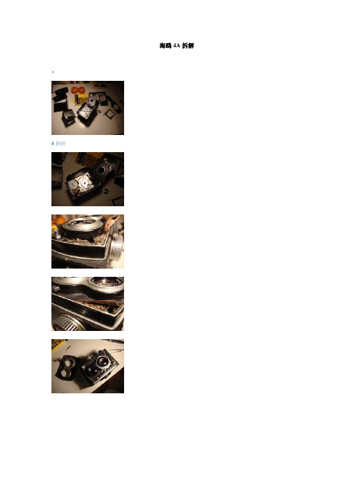
海鸥4A拆解>6回应1回应1回应快门机构3回应1回应。
> 返回倦猫的相册首页1回应4回应海鸥4A拆机记录想起那快门卡涩的海鸥4A,立马螺丝刀子伺候着.头一次打开它,没摸着门路,只是拆掉了磨沙取景器...反射板上全是灰..擦掉再说...琢磨半天..也没有打开前脸面板..开着面板的黑色饰皮,想..在它下面会不会有螺丝?勇敢的把饰皮撕掉..果然,有4颗螺丝.刚好.. 背着50/1.4 ,用它记录的,感受一下大眼睛的油润仔细的观察了它的连动结构...终于发现,快门拨杆和释放处有卡涩...用表板蜡处理的...轻轻的滴了一下.快门恢复正常拆是拆了...留张PP再说...前镜头动了...不差那点事咧..把后镜也拆掉好好的擦了一下...光亮如新前镜有一点点的霉斑,在下方,应该不影响成相!也难怪了...近40年的来机器了..装好!试机!呵呵..取景明朗通透..虽是原磨沙镜片,但成像立体凸现..所呈现的主题让你心动!!!这就是胶片机的魅力吧!但一想,心中又是一阵紧张..坏了!!!成相的前后镜头都动了!取景器是否和成相的焦点在一个点上????如不是,着机器岂不就废了??哎~~心里扑通扑通地..请教了"三只眼"一个色友..告之..(用一硫酸纸装在机器的后背上!后背打开,按下B门...从取景器条好焦距..用衣服把自己和相机一起遮住,只留下镜头..放大镜观察在硫酸纸上的成相)哈哈!!!效果杠杠的!!!!!喜!!。
海鸥4A拆解维修的几个小问题搞到一台成色一般但功能完好的4A,打算自个儿拆拆修修,昨晚搞了一晚上,今天手指疼,还没出啥活。
开个帖子,变拆变修变问大家问题,谢先,大家方便的话能上张实际的图最好,看图说话更直观些几个小问题向大家请教一下,在网上没找到的小问题:1. 放大镜部分说明:放大镜需要重新安装,零件包括,放大镜、锁定螺丝、一根小弹簧现状:放大镜已经被我安装在铁轴上,锁定螺丝、小弹簧未安装,目前是放大镜垂落,无法自然弹起、无法用螺丝锁定请教:1.1 如何保证放大镜弹起,感觉应该是压住跟铁轴连在一起的弹簧(图标1)的一边?还是怎样操作?1.2 如何保证螺丝跟小弹簧(图标3)锁定放大镜的位置、并同时保证螺丝上下拨动的弹性?2. 调焦旋钮部分说明:景深牌错位,需要拆解后调整位置现状:外侧黄色的玻璃压圈应该是最先拆解的部件,但是我不论顺时针还是逆时针都拆不下来。
2394AA s p e c t r u m a n a l y z e r w i t h o u t s t a n d i n g p e r f o r m a n c e a n d a u s e r f r i e n d l y v i s u a l i n tMarker TableThe marker system allows up to a maximum of 9 markers to be dis-played on the screen at any one time. A marker table shows the fre-quency and level of each marker selected thus allowing multiple sig-nals to be evaluated simultaneously. In addition to the Normal mark-ers 2394A provides Delta, Peak Search, Peak T rack, 1/Delta, Markerrack, Marker to Center and Marker to Reference capabilities.Measurement LimitsThe Limits facility allows an Upper and/or a Lower Limit to be seton the screen of the 2394A. Should the signal being displayed falloutside either limit a message will appear on the screen showingwhich limit has been exceeded and how many times this hashappened.X dB DownOccupied BandwidthChannel PowerHarmonic Distortion Adjacent Channel PowerS P E C I F I C A T I O NF R E Q U E N C YTuning Range1 kHz to 13.2 GHzRange Band1 kHz to 3 GHz 02.9 GHz to 6.4 GHz 16.3 GHz to 13.2 GHz 2All ranges employ fundamental mixing.Resolution1 HzFrequency Span Width100 Hz/div to 1000 MHz/div in 1, 2, 5 step selections (auto-selected) Zero span and Full span (1 kHz to 13.2 GHz)Manual selection of Start, Stop and SpanSpan Accuracy<±3% of indicated span widthReadout Accuracy± (Span Accuracy + Frequency Standard Accuracy + 50% of RBW) StabilityResidual FM <100 Hz p-p at 1 kHz RBW, 1 kHz VBW,(p-p in 200 ms)Noise Sidebands<-90 dBc/Hz at 10 kHz offset measured at 2.9 GHz-98 dBc/Hz at 100 kHz offset measured at 2.9 GHzF R E Q U E N C Y C O U N T E RResolution1 Hz, 10 Hz, 100 Hz and 1 kHzAccuracy±(Reference frequency error + frequency readout accuracy + counter resolution ±1 count)Sensitivity<-70 dBm from 50 kHz to 13.2 GHzA M P L I T U D EMeasurement Range+30 dBm to -110 dBmDisplayed Average Noise Level (DANL)300 Hz RBW, 10 Hz VBW, 50 Ωtermination-105 dBm @ 50 kHz to 100 kHz***************************************************************Pre-amp On-115 dBm @ 50 kHz to 100 kHz******************************************1 dB Compression Point>-10 dBm, 100 kHz to 13.2 GHz at 0 dB attenuation Displayed Range100 dB in 10 dB/div log scale50 dB in 5 dB/div log scale20 dB in 2 dB/div log scale10 dB in 1 dB/div log scale 10 divisions with linear amplitude scale Amplitude UnitsLog scale mode dBm and dBmV. Linear scale mode V (µV, mV, etc.) or dBV (dBmV only) Quasi Peak mode dBµV, dBmV or dBmDisplay Linearity5 and 10 dB/div, ±0.1 dB/dB, ±1.0 dB over 10 divisions1 and2 dB/div, ±0.5 dB over 10 divisionsLinear, ±10 % of Reference Level over 10 divisionsFrequency Response1 kHz to 5 MHz-3 dB to +1 dB5 MHz to 2.9 GHz ≤±1.0 dB2.9 GHz to 6.4 GHz<±1.5 dB6.4 GHz to 13.2 GHz<±2.2 dBA T T E N U A T O RRange0 dB to 55 dB in 5 dB steps selected manually or automatically coupled to the Reference LevelAccuracy±0.5 dB/step up to ±1.5 dB maximumR E F E R E N C E L E V E LRange-110 dBm to +30 dBm with 1 kHz filter using 1 dB/div scale Accuracy±1.0 dB (50 kHz to 13.2 GHz)Resolution0.1 dB stepsResidual Spurious-85 dBm (input terminated, 0 dB attenuation)Harmonic Distortion-60 dBc (-40 dBm input at 0 dB attenuation)Intermodulation Distortion-70 dBc 100 MHz to 13.2 GHz-65 dBc 1 MHz to 100 MHz (at -30 dBm input, 0 dB input attenuation)Other Spurious-60 dBc (10 MHz to 13.2 GHz at -30 dBm)R E S O L U T I O N B A N D W I D T HSelection-300 Hz, 1 kHz, 3 kHz, 10 kHz, 30 kHz, 100 kHz, 300 kHz, 1 MHz, 3 MHz9 kHz and 120 kHz (Quasi-Peak Detector, Option 4)100 Hz, 30 Hz, 10 Hz (Digital Resolution Bandwidth, Option 5) Accuracy±10% (Digital Resolution Bandwidth, Option 5)±20%For the very latest specifications visit Data Length7 bit or 8 bit selectableStop Bits1 bit or2 bitProtocolNone, Xon-Xoff, RTS-CTS, DTR-DSRE N V I R O N M E N T A LOperating0 to 40°CStorage-20 to +60°CTemperature & HumidityMeets MIL-T-28800E for Type 2, Class 5, non-condensing(85% operating, 90% storage)Vibration/ShockMeets MIL-T-28800E for Type 2, Class 5AltitudeOperational up to 3,000 m (19,842 ft.), non-operational to 12,200 m (40,026 ft).P R O D U C T S A F E T YConforms to EN61010-1 for Class 1 portable equipment and is for use in a pollution degree 2 environment. The instrument is designed to operate from an Installation Category II.E L E C T R O M A G N E T I C C O M P A T A B I L I T YComplies with the limits specified in the following standards:EN 55011: Class A and EN 50082-1G E N E R A L C H A R A C T E R I S T I C SDIMENSIONS350 mm (13.78 in.) W, 185 mm (7.28 in.) H, 395 mm (15.5 in.) D including handleWeight<12 kg/26.5 lbs (without options)Warm-up Time15 minutes for specified accuracyP O W E R R E Q U I R E M E N T SVoltage100 to 240 VAC ± 10%Frequency50 to 60 HzPower Consumption100 W max (without options fitted)H A R D W A R E O P T I O N SH I G H S T A B I L I T Y T I M E B A S E(O P T I O N03)Temperature Stability<±0.2 ppm/°C 0°C to 40°CAgeing Rate<±0.1 ppm/yrQ U A S I-P E A K D E T E C T O R(O P T I O N04)Quasi-Peak detector and EMC filtersRBW9 kHz Band B120 kHz Band C Frequency Range150 kHz to 30 MHz30 MHz to 1 GHz Charge Time (ms) 1 ±20% 1 ±20% Discharge Time (ms)160 ±20%550 ±20%Display Time (ms)160 ±20%100 ±20%D I G I T A L RE S O L U T I O N B A N D W I D T HF I L T E R S(O P T I O N05) Bandwidths100 Hz, 30 Hz, 10 HzBandwidth accuracy±20%Selectivity (-60 dB/-3 dB)<5:1Maximum span1 MHzSweep times for 10 kHz spanRBW100 Hz<0.9 sec30 Hz<3 sec10 Hz<4.5 secDisplayed Average Noise Levels (DANL) between 1 MHz and 13.2 GHz reduces DANL by typically 5 dB from the values in the 300 Hz resolution bandwidth filter.A C/D C P O W E R S U P P L Y(O P T I O N6)DC Voltage12 VDC to 21 VDCExternal Battery14.4 VDC @ 7 AHFor the very latest specifications visit For the very latest specifications visit 。
OMEGA5G Automatización para Portones LevadizosContrapesados de hasta 10 metros cuadrados¡Felicitaciones!Ud. ha adquirido el Motorreductor Eléctrico Marca MOTIC ModeloOMEGA 5G,Características Técnicascorriente absorbida_1,5 A.velocidad_1,7 rpm.ciclo de trabajo_30%.capacitor_10 micro faradios.tamaño máx. p/motor lateral_6 m2/1 brazo tel.velocidad de apertura/cierre_14/7 seg (según la versión).tipo de final de carrera_normal cerrado.tamaño máx. p/2 motores en paralelo_ hasta 12m2/2 brazos.1- Motor 5G Omega.2- Una central Q50/Q20/Q7-8 y sus controles TX5G.3- Una base de fijación.4- Un brazo Telescópico con Espada y Funda, Planchuela de Fijación BTornillo y Tuerca Auto-Frenante, total 6 piezas.ESCANEARCON CELULARpara Portones Levadizos.potencia nominal_340 W.alimentación_220 V.4Contenido de la Cajafijar la base al motorPaso 1 Para jar la base del motor, se puede soldar 2 planchuelas con ori cios roscados en loscuales se atornillará la misma, o bien soldar la base directamente al portón.colocar el motorPaso 2 Instalar el motor en su base, colocando los tornillos pasantes. El motor instalado debequedar como se muestra en la imagen.Dimensiones610610150145Abrir manualmente el portón y ajustar el prisioneroal buje para que no se desprenda. Cierre el portónmanualmente y gire nuevamente la manija de desbloqueo en sentido contrario.colocación del brazo telescópicoPaso 3Suelde el buje en el extremo de la espada. Gire la manija de desblo-queo del motor y acople el buje al eje estriado.Soldar un soporte al marco jo del portón para que la vaina pueda pivotearlibremente.Paso 5 programación electrónica de su motorSu motor viene equipado con una placa Q50/Q20/Q7-8.Diríjase al manual de la placa que acompaña a su motor o escanee el código que corresponda para acce-der a los vídeos de Youtube que le explicarán en simples pasos cómo con gurarla.Paso 7 instalación de cerradura eléctrica / barrera infrarroja (opcional)Estos accesorios son opcionales. Para su instalación, por favor referirse a los manuales de los mismos, en el manual de la central o consulte a su profesional de con anza.Paso 4 instalación eléctricaEsquema general de la instalación eléctrica. Utilice siempre un interruptor termomagnético paraproteger la instalación, y no olvide conectar el cable de tierra al bastidor del equipo.1/ motor. 2/ transmisor. 3/ fotocélulas. 4/ semáforo. 5/ selector a llave.6/ tablero c/llave térmica. 7/ caja depase.Recuerde colocar precintos para sujetar el cableado a la vaina como se ve en la imagen. De esta forma, no se atrapará con el movimientodel portón.Paso 6 colocación de tapa plásticaPara nalizar la instalación del motor, colocar la carcasa de plastico./ Mantenga alejados los controles y cables del alcance de niños y mascotas. El portón podría accionarse accidentalmente o sufrir lesiones./ Siempre corte el suministro eléctrico antes de operar manualmente el portón o realizar tareas de limpieza./ Evite aproximarse o caminar a través del portón. Su activación puede ocasionar accidentes./ Examine con frecuencia la instalación en busca de signos de desgaste o daño en los cables. Póngase en contacto con perso-nal autorizado en caso necesario.La garantía de los elementos o servicios vendidos por Grupo Motic SRL , (en adelante Motic ) aplica solo a los productos La garantía se reduce al reemplazo del producto defectuoso o a la reparación del mismo, dentro de un plazo de 10 días (dependiendo de la existencia de repuestos), a elección de Motic y a su solo criterio, no cubriendo las conse-cuencias ni costos ni daños emergentes ni daños contingentes que hubiera podido provocar o serles atribuidas a la falla.La garantía abarca única y explícitamente desperfectos de fabricación del equipo que no se encuentren relaciona-dos a errores en su aplicación, instalación, su uso en condiciones anormales o condiciones ambientales o meteo-rológicas extremas.La garantía se brinda en las instalaciones técnicas de Motic (su Domicilio Comercial) por lo que los equipos deben-dos o autorizados.Esta Garantía es Limitada y está sujeta a las condiciones y legislación vigente en la República Argentina,Para cualquier solicitud de cobertura de la Garantía, Reparaciones o Repuestos o cuestiones técnicas comunicar-se con Motic en Laprida 3130,Teléfono (011) 4730-3222 en Villa Martelli (1603) Buenos Aires, Argentina. Este equipo está diseñado para uso residencial y no comercial, industrial o de alta demanda.garantíaPlazo de la Garantía para los motor r eductores es de 2 (Dos) años a partir de la fecha de la factura. Las Controladoras electrónicas tienen 1 (Uno) año de garantía, los controles remotos 6 (Seis) meses, las pilas y otros consumibles no tienen garantía.。
FANTASTIC COLORFUL UNDERWATER PICTURESSeaLife high definition cameras: All models can be used above and below water comfortably and deliver great images.newMICRO 2.0 (64GB & 32GB) MICRO HD 1.0 (16GB)Image Sensor 16-Megapixel SONY CMOS 14-Megapixel CMOS Movie Resolution HD/1080p @ 60 fps or 1296p @ 30 fps HD/1080p @ 30fps or 720p @ 60 fps Memory 64GB (25000 images/12hrs video) 16GB (4000+ images/3hrs+ video) 32GB (12000+ images/6hrs+ vidéo) Focus Range 30 cm to infinity 30 cm to infinity Download/share WIFI via Sealife Micro Cam App or via cable Cable LCD 2.4“ TFT LCD color display 2.4“ TFT LCD color display Field of View 130° Super Wide, 100° Wide, and 80° Standard 140° Super Wide, 130° Wide, and 90° Standard Depth Individually depth tested to 60 m Individually depth tested to 60 m Dimensions: 279g & 10.7 x 5.3 x 7.4cm 266g & 10.7 x 5.3 x 7.4cm Battery Lithium rechargeable (3.7V, 2350 mAh) Lithium rechargeable (3.7V, 2400 mAh) Battery life 3+ hours (Approximately 1000+ images/ 3+ hours video)TECHNICAL CHARACTERISTICSMICRO HD 1.0 - 16GBMICRO 2.0 - 32GB WIFI & 64GB - WIFIThe MICRO HD range of cameras are permanently sealed and absolutely flood-proof. Easy to use, with nothing to maintain.With rich, colourful still images, full 1080p HD video, instant focusing, and a built-in 130-degree Fisheye Lens, the Micro 2.0 has everything needed to capture and share your underwater encounters down to 60 meters.The Micro 2.0 includes two shooting modes: time lapse shooting and upside-down shooting and is available in two capacities: 32GB with WiFi, or 64GB with WiFi, connecting wirelessly to smartphones and tablets with the SeaLife Micro Cam app.UNDERWATER CAMERA SETSMICRO 2.0 1500 PROThe SeaLife Micro 2.0 1500 Pro set includes thepermanently sealed Micro 2.0 32GB WiFi camera,Flex-Connect Micro Tray, Grip, Flex Arm, SeaDragon 1500 Lumen Light and travel case.MICRO 2.0 2500 PROThe SeaLife Micro 2.0 2500 Pro set includes thepermanently sealed Micro 2.0 64GB WiFi camera,Flex-Connect Micro Tray, Grip, Flex Arm, SeaDragon 2500 Lumen Light and travel case.SEA DRAGON PHOTO-VIDEO LIGHTS 2500, 2100, 2000 & 1500• One button control for easy operation - one button to power light on/off, select brightness and switch beam angle • Depth rated to 60 meters - Guaranteed• Easy to expand with Flex-Connect™ trays, grips and Flex Arms, handle, Y-S, ball joint, cold shoe and other accessories • Quick-release button to detach light and aim in crevices and hard to reach areas • Corrosion-proof metal light head for heat dispersion and durability• Waterproof battery compartment - even if the O-ring seal fails, the battery compartment is isolated so water cannot reach the internal electronics • Universal mounting screw fits SeaLife and other brands of underwater cameras w/ standard ¼-20 tripod mountSEA DRAGON 2000Shown with DC1400SEA DRAGON 2100Shown with MICRO HD 1.0SEA DRAGON 2500Shown with MICRO HD 1.0Brightness (lumens) 2500 2100 2000 1500Beam angle 120° 100 ° or 15 ° (spot) 100° 120°Effective Range 1.2m 1.2m 1.2m 1.0m Color Rendering Index 90 72 72 80Bulb COB LED 7 x 3W LED (CREE XML2 LEDs) 6 x 3W LED (CREE XML LED) COB LED Bulb Life: 35 000 hours 35 000 hours 35 000 hours 35 000 hours Battery (included) L-Ion 7.4V, 3400 mAh, 25Wh L-Ion 7.4V, 3400 mAh, 25Wh L-Ion 7.4V, 3100 mAh, 23Wh L-Ion 7.4V, 3400 mAh, 25Wh Battery Run Time: 60 minutes at full power/120 minutes at half power/240 minutes at quarter power 70 mins (full power) Dimensions 12.2 x 5.6 x 9.7 cm (head only) 13 x 5.6 x 9.7 cm (head only) 22 x 24 x 6 cm (Set) 12.2 x 5.6 x 9.7 cm (head only) Weight 371g (head only) 450g (head only) 652g (Set) 371g (head only)SEA DRAGON 1500Shown with MICRO 2.0TECHNICAL CHARACTERISTICSDIGITAL SEA DRAGON FLASHR educes backscatter and produces bright, deep colors in underwater photos. Adjustable or Auto Mode brightness for optimal exposure. Underwater range: up to 2,5m. Includes snap-on diffuser, standard tray, grip and case. Not compatible with the MICRO range.SEA DRAGON MINI 600Apowerful 600 lumen LED using the new CREE XM-L@ LED for multiple applications down to 100m, 75° wide beam angle, delivered with two CR123 lithium batteries giving 150 minutes burn time at 40% power and 60 minutes at 100% power, also compatible with 18650 Li 3.7v battery giving 250 minutes burn time at 40% power and 100 minutes at 100% power, easy on/off light head twist control, includes GoPro° camera mount, universal Y-S adapter and lanyard clip. The Mini 600 is now equipped with an over-pressure valve to release battery off-gassing.Dimensions : 96.5g (without batteries) & 3.4cm (diameter) x 13.5 cmSEA DRAGON MINI 650The compact and ergonomic Sea Dragon Mini 650 Flood provides 650 lumens across a wide 120-degree beam that is ideal for brightening your photo or video subject, or illuminating a large area on your dive. The Sea Dragon Mini 650 Spot has a concentrated 15-degree beam (10-degrees underwater) that is ideal for pointing out sea creatures and covering long distances to illuminate your dive.The light features single button operation and is powered by two CR123 batteries (included) or an optional rechargeable lithium ion battery (Tenergy 18650 2600mAh 3.7v) delivering up to 100 minutes of burn time at full power. Depth tested to 100 meters. Dimensions : 189g (without batteries) & 4.1cm (diameter) x 15.9 cm.Guide Number20m full power/1.5m low powerCoverage Angle 80° horizontal x 60° vertical (100° with included diffuser)Color Temperature 5700 degrees KelvinPower Source 4 AA batteries (NiMH recommended)Battery Life 150 flashesDimensions509g (with batteries) & 12.7 x 11.4 x 6.4 cmQuickly and easily expand your camera set with flex-connect accessories - add grips, Flex Arms, trays and more with just a “click!” flex-connect allows you to transform your camera set from compact to full-featured in just seconds, providing a quick way to adjust to any diving environment. To assemble and disassemble just in seconds.MICRO/DUAL TRAYSChoose between two tray sizes and build your ideal system. For maximum illumination and stability.Sea Dragon 2000flex-connect Flex Armflex-connect GripFisheye Wide Angle Lensflex-connect Dual TrayDC1400 Cameraflex-connect Flex ArmSea Dragon Flash‘Flex-Connect’ is a range of Sealife Accessories. The trays, mounts and flex arms allow you to easily expand your camera set. Modular for travel and they quickly and easily lock into place.Flex Arms extend lights with 100° of silent bending motion. Cold Shoe Mount and Micro Tray provide an incredibly compact set-up. Dual Tray enables you to connect multiple lights to your camera.BEGIN BY CHOOSING YOUR TRAY .....FLEX ARMThe Flex Arm can be bent up to 100° and adds 7” of length, so you can aim the light exactly where you need it.COLD SHOE MOUNTUse the Cold Shoe Mount to mount a light directly to your camera for an ultra compact system. You can also use the GoPro® Adapter to mount a GoPro® directly above your camera in order to simultaneously capture underwater photos and video.GOPRO® ADAPTEREasily and safely connect the GoPro® camera to Flex-Connect accessories.YS ADAPTERThe YS Adapter makes the SeaLife system compatible with any underwater light or flash using a YS mount.HANDLEUse the Sea Dragon 1200 or 2000 lumen light as a handy dive light. Just click the light onto the Handle and you are ready to go. Of course, the H andle in combination with the GoPro® Adapter can also be used for the GoPro®, creating an extremely comfortable grip for comfortable GoPro® images.BALL JOINT ADAPTERThe adapter connects Sea Dragon Lights and Flex-Connect accessories to any underwater camera using the 1”/25mm ball joint mounting system.MICRO HD ADAPTERAdapter to connect your Micro HD to GoPro® accessoriesTRAY HANDLEThe Flex-Connect Grip provides a comfortable grip and improved handling for your light, flash or underwater camera set.THEN ADD HANDLES AND ARMS....35.5X27.9X12.7cmThe illustrations in this catalog may not exactly represent the products described and are intended as a guide only. We reserve the right to alter product descriptions or specifications as necessary.© Copyright 2015 SCUBAPRO. Johnson Outdoors Diving, LLC.FISHEYE LENSThe fisheye lens has an effective focal length of 16mm and increases the field of vision of the DC1400 by 80%. This allows for incredible perspective shots under water.10X CLOSE UP LENSThe 10x close-up lens allows you to get even closer to your subject.AQUA PODThe 135cm Aqua Pod allows you to take photos and videos from creative perspectives and to take selfies, close-ups, and videos while maintaining enough distance between you and your subject. The Aqua Pod Mini extends to 95cm and is comfortably light.GoPro® with Aqua Pod and Mini 600W IDE ANGLE LENSY ou want to fit everything into the shot and stay within the shooting range of your flash. The wide-angle lens takes a full-frame picture of a 5’ shark within 5’shooting distance.Not compatible with DC1400 or MICRO range.OBJECTIVE GRAND ANGLE MINIAmust-have lens for divers. Get closer to the subject and still fit everything in the picture. Not compatible with DC1400 or MICRO range.Absorbs moisture to prevent fogging and corrosion of your SeaLife camera.M OIST URE MUNCHER S OFT PRO CASEB UOYANCY WEIGHT AND FLOAT STRAPL-ION BATTERIEFor SeaDragon Photo-Video lights.BATTERIES & CHARGERFor SeaDragon Mini 650 & Mini 600OTHER ACCESSORIES。
READ AND SAVE THESE INSTRUCTIONSTechnical SpecificationsCheck the fan label to make sure it is the correct voltage.Operating voltage Diameter Weight Operating frequency120 VAC, 1 Φ132 cm 5 kg 60 Hz 220/240 VAC, 1 Φ132 cm5 kg50/60 HzTools Needed• Ladder• Wire Strippers• Phillips Screwdriver • Hex Key •WrenchesModels: L3127-X5, L3127-X6, FR127C-U1EXXScan or visit /support for online Haiku mobile app helpMounting Bracket Control Box Wiring Cover LED Diffuser RingMounting Ball and Hardware Lower Cover Trim Lower Cover Ring Extension Tube Motor Unit (3) Airfoils Remote Control Hardware PackPARTScdefHARDWAREHardware and tools needed for installation are packaged in the hardware pack. Hardware below shown at actual size.Mounting Hardware M8 Bolt M8 Washer M8 Nylock NutAirfoil Hardware(6) M5 Screws with Tooth WasherLower Cover HardwareMounting Ball and HardwareSteel PinWedge4 mm Self-TappingScrewMounting Ball (2) Painted M3.5 ScrewsorWiring Cover Hardware(4) M4 Socket Head Cap Screws3HAIKU® BY BIG ASS FANSPREPARE THE FAN SITEInstallation requires basic electrical knowledge. Contact a licensed electrician if you areuncomfortable performing electrical work or if legally required in your area.21Disconnect Power!Disconnect power to the fan location before wiring fan!If required by your local electrical code, a licensed electrician must install the fan.The ground wire must be connected to the supply ground and its length must be longer than the safety cable!A readily accessible disconnect device shall be incorporated external to the equipment.A means for disconnection must be incorporated in thefixed wiring in accordance with the wiring rules.If you are installing the fan directly to the building structure or to a ceiling-mounted outlet box, the structure or outlet box must besuitable for fan support.4REV. H 08/27/2019 | © 2015 BIG ASS FANS | ALL RIGHTS RESERVEDOutlet BoxIf your local electrical code requires the fan to be installed on a ceiling-mounted outlet box, the outlet box must be suitable for fan support. If there is not an outlet box at the fan location, one should be installed on a ceiling joist or beam and properly wired.Concrete CeilingIf installing your fan on a concrete ceiling, ensure power wiring has been routed to the fan site. Attach the mounting bracket directly to the ceiling using four Ø 6 mm anchor bolts (not supplied). If required by your local building and safety code, install an Ø 8 mm anchor hook (not supplied) for the safety cable.Wood Ceiling JoistIf installing your fan on a wood ceiling joist, ensurepower wiring has been routed to the fan site. Attach the mounting bracket directly to the joist using two wood screws (not supplied). Big Ass Fansrecommends using corrosion-resistant 12-11 x 45 mm hex head timber screws with seal.INSTALL THE MOUNTING BRACKET5HAIKU® BY BIG ASS FANSOutlet BoxPage 6Wood Ceiling JoistPage 10Concrete CeilingPage 8INSTALL THE MOUNTING BRACKET (OUTLET BOX)a6REV. H 08/27/2019 | © 2015 BIG ASS FANS | ALL RIGHTS RESERVEDHAIKU® BY BIG ASS FANS STEP COMPLETEDSecure the mounting bracket (a) to the outlet box (b) with the screws supplied with the outlet box (c). Outlet Box Hardware:c. Screw (supplied with outlet box)7≥5mmb b bb8REV. H 08/27/2019 | © 2015 BIG ASS FANS | ALL RIGHTS RESERVED INSTALL THE MOUNTING BRACKET (CONCRETE CEILING)Use the mounting bracket as a template tomark drill locations for the four mounting holes.Install an anchor hook forthe safety cable if requiredby your local building andsafety code.STEP COMPLETEDUsing the mounting bracket (a ) as a template, mark drill locations for the four mounting holes on the concrete ceiling. Drill four Ø 11–12 mm holes into the marks. The hole depth should be at least 50 mm.Remove any dust from the holes. Insert four anchor bolts (b ) into the holes. Strike the heads of the anchor bolts with a hammer, ensuring the bolt sleeves are flush with the ceiling surface.Concrete Ceiling Hardware:b. (4) Ø 6 mm anchor bolts (not supplied)Position the mounting bracket on the anchor bolts. Ensure all four anchor bolts are fully tightened to expand and lock the anchors.If required by local building and safety codes, install an anchor hook (c ) for the safety cable. Drill a Ø 13–14 mmhole for the anchor hook. The hole depth should be at least 65 mm. Remove any dust from the hole, and then insert the anchor hook and fully tighten. Refer to the Safety Cableinstructional sheet included with this guide.Concrete Ceiling Hardware:c. Ø 8 mm anchor hook (not supplied)3214INSTALL THE MOUNTING BRACKET (WOOD CEILING JOIST)tSecure the mounting bracket (a) to the joist with two (2) 12-11 x 45 mm hex head timber screws with seal (b).Wood Ceiling Joist Hardware:b. (2) 12-11 x 45 mm hex head timber screws with seal (not supplied)STEP COMPLETEDPREPARE THE AIRFOILS312SELECT LENS(BLACK FANS WITH LIGHTS)MATCH AIRFOIL STICKERS1Black fans with lights: For softer lighting, remove the white lens and install the smoky lens before attaching the airfoils.a. Twist to uninstall white lens.b. Twist smoky lens to lock in place.2Make sure the stickers on the airfoils match the stickers on the fan hub.Rest the motor assembly (a ) on your lap. Moving clockwise, install each airfoil (b ) with the provided hardware. Tighten the screws to 2.5 N·m (22.1 in·lb). Do not use power tools to install the airfoils, and do not over-tighten the screws! Over-tightening the screws may cause the airfoils to warp and void your warranty.Airfoil Hardware:c. (6) M5 screws with tooth washerFans without lights: Position the motor cover (d ) over the motor, and then place both hands flat on the cover and turn it clockwise to lock it in place.STEP COMPLETEDDO NOT USE POWER TOOLS!211Lower the extension tube (a) onto the motor shaft. Ensure the yellow arrow sticker on the extension tube is aligned with the sticker on the motor.CONNECT MOTOR WIRING AND SECURE EXTENSION TUBERemove the tie holding the wiring harnesses to the extension tube. Plug the two large wiring harnesses (a ) into the receptacles on the motor. Plug the small, male wiring harness (b ) into the female wiring harness from the motor shaft.Align the bolt holes on the extension tube with the holes on the motor shaft, and then secure the tube with the provided hardware and wrenches.Mounting Hardware:21Place the lower cover ring (a ) around the extension tube, resting it evenly on the motor. There should be a very small gap between the cover and the airfoils. Rotate the cover ring clockwise until it stops.Thread the wires through the opening in the lower cover trim (b ), and then slide the trim down the extension tube, resting it evenly on the cover ring.Align the screw holes on the trim with the motor screw holes, and then secure the trim in place with the provided screws (c ).213ARRANGE LED DIFFUSER RING, WIRING COVER, AND MOUNTING BALLcSlide the LED diffuser ring (a ), wiring cover (b ), and mounting ball (c ) down the extension tube (in that order), resting them on the fan hub.Do not seat the LED diffuser ring in the wiring cover at this step!ATTACH THE MOUNTING BALLSEAT MOUNTING BALLINSTALL WEDGEInsert the steel pin (a ) into the hole at the top of the extension tube, and then slide the mounting ball upward, seating the steel pin in the inner slots of the ball.Mounting Ball Hardware:a. Steel pinInsert the wedge (b ) into the mounting ball as shown, and then secure the wedge with the screw (c ). Tighten the screw enough to prevent movement between the mounting ball and extension tube. Do not over-tighten 21Raise the fan to the mounting bracket. Align the slot in the mounting ball with the rib in the mounting bracket, insert the mounting ball, and let the fan hang freely.Gently twist the extension tube to ensure the mounting ball is properly seated and will not move during fan operation.STEP COMPLETED21Route the ground wire from the extension tube (a) to the outside of the mounting bracket. Secure the ground wire terminal (b) to the mounting bracket with the screw (c).STEP COMPLETEDMake sure power is disconnected before wiring the fan!If required by your local electrical code, a licensed electrician must install the fan.Do not connect the fan to a damaged power source! Do not attempt to resolve electrical failures on your own. Consult a qualified electrician if uncertain of the electrical installation of this fan.Make the electrical connections by securing the supply power wires to the loose ends of the wiring harness (a ) with the provided wire nuts or a terminal strip (or the means of connection required by your local electrical code).Test the connection by lightly tugging on the wires.Tuck the power wiring into the outlet box or building structure.321INSTALL THE CONTROL BOXInsert the control box (a ) into the mounting bracket as illustrated. Be careful not to pinch the wires between the mounting bracket and control box!Snap the LED indicator (b ) into the gap in the mounting bracket. Make sure it is securely seated.21CONNECT THE CONTROL BOX2Connect the wiring harness from the control box (a ) to the harness from the ceiling (b ).Peel the backing off the double-sided tape (c) on the mounting bracket, and then affix the harnesses to the tape.Connect the wiring harnesses from the extension tube (d ) to the corresponding receptacles (e ) on the control box.12INSTALL THE WIRING COVER15ALIGN WIRING COVER INSTALL SCREWS INSTALL DIFFUSER RINGSlide the wiring cover (a ) up the extension tube, aligning the yellow arrow stickers so that the top of the wiring cover sits flush with the mounting bracket. Make sure the LED indicator receptacle shows through the opening in the cover (b ).Make sure all wiring is tucked into the wiring cover, and then secure the cover with the provided screws (c ).Wiring Cover Hardware:c. (4) M4 socket head cap screwsSlide the LED diffuser ring (d ) up the extension tube and plug the connector into the LED indicator receptacle through the opening (b ) in the wiring cover.Make sure the tabs on the diffuser ring are securely snapped in place.12STEP COMPLETED3TEST THE FANDo not expose the remote control to rain or water.Turn on power to the fan location and test functionality using the remote. Turn on the fan and test speed and light brightness*.*Applies only to fans with lightsTurns fan on or off.Sets fan timer length of up to eight hours.Each press extends timer by one hour.Turns light on or off.Clears active fan timer.Increases fan speed/light brightness.Varies fan speed to simulate a naturalbreeze.Decreases fan speed/light brightness.Automatically adjusts your fan speed overnight to keep you comfortable while you sleep.For operation, maintenance, and troubleshooting information, visit /supportNOTESNOTES© 2015 Big Ass FansThe information contained in this document is subject to change without notice. May be protected by one or more patents listed at /patentsHaiku is a trademark of Delta T LLC, registered in the U.S. and/or other countries.For warranty information, visit /product-warrantiesUnited States2348 Innovation DriveLexington, KY 40511+1 855 694 2458Australia 35 French Street Eagle Farm, Brisbane, QLD /au +61 1300 244 277Southeast Asia 2348 Innovation Drive Lexington, KY /sg Singapore: +65 6709 8503Malaysia: +603 5565 0888All Other Geographies2348 Innovation DriveLexington, KY 40511+1 859 233 1271LP。