耐普顿计量泵
- 格式:pdf
- 大小:154.42 KB
- 文档页数:2
耐普顿计量泵 美国耐普顿(Neptune)化学泵公司是一家以生产液压隔膜计量泵、电厂化学设备及搅拌器为主的知名公司,总部设在宾夕法尼亚州费城并在加拿大设有分厂。
耐普顿与著名的威尔顿(WILDEN)公司、百马(BLACKMER)公司等同隶属于美国PSG集团(Pump Solution Group),是美国五百强Dover集团的子公司。
它下属三家兄弟公司:耐普顿(Neptune)公司(主要以生产计量泵和加药设备)、混合器(Mixer)公司(主要生产搅拌器)、水设备(Waters Equipment)公司(主要生产水汽取样分析设备)。
耐普顿公司主要产品有500系列、600系列液压隔膜计量泵,7000系列机械隔膜计量泵、电磁计量泵及成套的加药设备(可根据客户要求定制)。
其中,它的液压隔膜计量泵通过其独有的油路可变旁路系统调节冲程长度来实现流量的调节,其性能要远远优于传统计量泵,并且使用寿命更长、能耗更低、体积更小。
Neptune 600系列泵以其高压力、高稳定性,是电厂加磷酸盐理想用泵。
此外耐普顿公司还为各系列计量泵提供合适的电动或气动冲程调节器、隔膜监测器、背压阀、脉冲阻尼器等高品质附件。
水设备公司可为客户提供优质的水汽取样设备、冷却器、水汽分析设备等。
混合器公司的各种材质不同型号的搅拌器可广泛应用于各种化学品的溶解、乳化、混合、絮凝等。
它的坚固耐用和稳定性得到客户的一致认可。
这些产品以优良的品质、理想的价格被应用于国内一些著名的工程。
例如:大亚湾核电站、上海华能电厂、福州华能电厂、珠海发电厂、丹东华能发电厂、合肥第二发电厂、台州电厂等。
耐普顿化学泵公司凭着其严谨的商业情操和优秀的产品为众多行业的客户提供着最优秀的服务。
在欧美的电力、化工、水处理等行业中,耐普顿拥有众多的忠实客户,并且一直为客户的成功增添动力。
耐普顿希望也能为您提供优质的服务,推动您事业的腾飞。
PROMINET计量泵PROMINET普罗名特公司的产品有各种精密计量泵、测量传感器、检测控制装置、臭氧发生装置、二氧化氯发生装置、紫外线消毒装置、化学药品投加装置、重力过滤器、砂滤、活性炭过滤、微滤、超滤、钠滤等过滤设备、反渗透装置以及高品质饮用水处理设备、海水淡化设备、全套泳池水处理设备、污水处理设备等,公司的技术和产品已具有世界领先水平。
PROMINET普罗名特电磁计量泵应用领域:化学品计量最大75 l/h饮用水处理:投加消毒剂冷却循环水:投加消毒剂污水处理:投加絮凝剂造纸行业:投加添加剂塑料生产:投加添加剂PROMINET普罗名特电磁计量泵优点:仅有一个移动部件,驱动部件无磨损。
泵运行时无需润滑轴承或轴。
保养和维修费用很低具有极好的持续运行能力alpha c隔膜计量泵计量范围:1.0-30.6 l/h,10-2 bar电机驱动计量泵是为简易操作而设计的计量泵,特别适用于需连续计量的场合。
Beta电磁隔膜计量泵计量范围:0.74-32 l/h,25-2 barBeta电磁计量泵能够满足现代水处理和化学品计量中所有调节和控制功能的要求。
相比以前,其特点为脉冲步进降低和增加的功能。
这样更容易接受外部信号传感器的精确调节。
针对实际要求更简单精确的调节计量。
Concept c电磁隔膜计量泵计量范围:0.72-24 l/h, 16-1.5 bar由微处理器控制,短冲程、电磁驱动的隔膜型计量泵。
CONCEPT c系列计量泵以其精巧的结构、可靠的性能、优越的性价比而为大多数OEM客户所接受。
由于泵头材质具有良好的耐化学腐蚀性能,因而可以对各种工艺过程中几乎所有化学液体进行精确计量。
不但可手动控制,也可通过外部的脉冲或模拟信号控制。
Concept plus电磁隔膜计量泵计量范围:0.74-19.9 l/h, 10-1.5 bar结构紧凑,非常适合对含氯的溶液进行开关控制或比例控制。
安装简便,可以安装到罐子上或墙上。
南方赛珀计量泵说明书一、产品介绍南方赛珀计量泵是一种用于输送流体的设备,采用计量泵原理,能够精确地控制流体的流量和压力。
该计量泵具有结构紧凑、性能稳定、操作简便等特点,广泛应用于化工、石油、制药等领域。
二、产品结构南方赛珀计量泵由泵体、驱动装置、计量装置和控制系统等部分组成。
泵体通常由不锈钢材料制成,具有良好的耐腐蚀性能,能够适应不同介质的输送需求。
驱动装置采用电机驱动,能够提供稳定的动力源。
计量装置通过精确的测量机构,实现对流体流量的准确控制。
控制系统则负责监测和调节泵的工作状态。
三、工作原理南方赛珀计量泵的工作原理基于容积变化的原理。
当泵体扩大时,吸入液体;当泵体缩小时,排出液体。
通过驱动装置的控制,使泵体不断地扩大和缩小,从而实现液体的连续输送。
计量装置通过对泵体容积的测量,实时监测液体的流量,并通过控制系统的反馈,调节驱动装置的工作状态,以达到精确控制流体流量的目的。
四、产品特点1. 精确计量:南方赛珀计量泵采用高精度的计量装置,能够实现流体流量的精确控制,保证输送过程中的准确性。
2. 高效节能:该计量泵采用先进的驱动装置和控制系统,能够实现高效的泵送过程,并且具有节能的特点。
3. 耐腐蚀性强:泵体采用不锈钢材料制成,能够适应各种腐蚀性介质的输送需要。
4. 操作简便:南方赛珀计量泵的操作界面友好,操作简单方便,无需专业技术人员即可进行操作和维护。
5. 结构紧凑:产品体积小巧,结构紧凑,占用空间小,适用于各种场所。
五、适用领域南方赛珀计量泵广泛应用于化工、石油、制药、食品等领域,可以用于各种介质的输送,如液体、气体、悬浮液等。
其精确的计量能力,使其在需要精确配比的工艺中得到广泛应用,如化工生产、药品配制等。
六、使用注意事项1. 在使用前,请仔细阅读本说明书,并按照操作规程正确使用计量泵。
2. 在使用计量泵时,应根据实际工艺要求,正确设置流量和压力参数。
3. 在计量泵运行过程中,应定期对设备进行维护保养,确保设备的正常运行。
甲醇计量泵安全操作及保养规程甲醇计量泵是一种常用的流体输送设备,主要用于输送甲醇等液体,同时需要注意其安全操作和保养规程。
本文将从以下几个方面介绍甲醇计量泵的安全操作和保养规程。
安全操作规程1. 负责人员要经过专业培训负责使用甲醇计量泵的人员需要经过专业培训,掌握其工作原理和操作流程,了解甲醇计量泵的结构和使用特点,同时应该学习基本的安全操作知识和应急措施,确保能够熟练、准确地使用和操作甲醇计量泵。
2. 安装方位注意甲醇计量泵的安装位置应该选择干燥、通风、光线充足的地方,不能安装在潮湿、阴暗、气味异味的地方。
若是在室内使用,则要设置防爆措施,以防出现安全事故。
3. 操作时要严格遵守操作规程使用甲醇计量泵时,必须严格遵守操作规程,不得草率从事操作行为。
在使用过程中,应正常开动、停机,不能在泵体下方或周围乱堆放杂物,确保通风、检测通风口是否畅通。
4. 防护设施不能疏忽在安装甲醇计量泵时,应该配置好必要的防护设施,如防爆设施、防震设施和泄漏报警装置等,以确保人员和泵设备的安全。
5. 事故发生后应及时止损在甲醇计量泵使用过程中,若出现任何异常情况,如泄漏等意外事故,负责人员应该熟练掌握相关紧急处理方法,迅速采取应急措施,争取最快速到达现场进行处理,尽量减少事故带来的负面影响。
保养规程1. 定期清洗甲醇计量泵的运行会产生一定的污垢,影响泵的正常使用,因此需要定期清洗泵体和管路,欲了解安全清洗操作方法请参阅清洗手册,掌握其深入更换零部件的方法。
2. 定期更换易损件甲醇计量泵的易损部件主要包括密封件和电机。
在日常维护中,需要定期对这些部件进行检查和更换,确保甲醇计量泵的正常运行。
3. 定期维护润滑甲醇计量泵在长时间使用或负荷较大时,需要进行润滑维护,尤其是要注意防止运行中过热,其加油量不应该过多或过少。
4. 定期检测和保养定期检测和保养甲醇计量泵不仅是为了系统运行稳定,更是为了系统寿命更长。
检测时应注意检查泵设备各项指标是否符合规定要求,如需要进行调整,则应进行及时的调整并记录。
数字计量泵欧姆尼安全操作及保养规程数字计量泵欧姆尼是一种数字化配药设备,通常用于医院和制药厂等场合。
在使用数字计量泵欧姆尼的过程中,为了保证安全性和准确性,需要掌握一些操作和保养规程。
本文将详细介绍数字计量泵欧姆尼的安全操作和保养规程。
安全操作规程1. 泵头清洗每次使用数字计量泵欧姆尼时,都需要对泵头进行清洗,以避免交叉感染。
具体步骤如下:1.将泵头从数字计量泵欧姆尼上取下;2.将泵头放入洗涤槽中进行清洗;3.清洗完毕后,使用 70% 的酒精进行消毒。
2. 防止气体阻塞在使用数字计量泵欧姆尼时,需要注意泵头是否出现气体阻塞现象。
如果出现气体阻塞,会影响药品的配药准确性。
为避免气体阻塞,需要按照以下步骤操作:1.先将泵头放置于空气中,尝试满盘气体;2.然后用 70% 的酒精浸泡几分钟,在药品配制之前彻底干燥。
3. 泵头安装泵头安装时,需要注意以下几点:1.在插入数字计量泵欧姆尼之前,确保泵头干燥,并且没有任何杂质和残留物;2.确认泵头是否正确连接模块;3.确保泵头已经正确安装畅通无阻。
4. 操作步骤使用数字计量泵欧姆尼时,要按照以下步骤进行操作:1.确认药品的剂量;2.将药品输入泵头;3.调整药品的流速;4.监测药品配制过程。
保养规程1. 泵头维护定期维护泵头,可以确保数字计量泵欧姆尼的正常工作。
维护的步骤如下:1.每周清洗一次泵头,并且使用 70% 的酒精进行消毒;2.每月检查泵头连接情况,是否有松动;3.每半年更换一次包裹滤器;4.每年更换一次台湾进口 LD 泵头。
2. 清洗和维护数字计量泵欧姆尼定期清洗和维护数字计量泵欧姆尼可以延长设备寿命,确保其正常工作。
具体操作如下:1.每天清洗控制器表面,并用消毒酒精进行消毒;2.每月清洗和消毒数字计量泵欧姆尼的全部外壳;3.每季度检查数字计量泵欧姆尼运行状况,如有异常要及时联系售后人员进行维修。
以上就是数字计量泵欧姆尼的操作和保养规程。
只有掌握了正确的操作和保养方法,才能保证数字计量泵欧姆尼的正常运作,确保药品的配制准确性和下次用时没有交叉感染的隐患。
米顿罗计量泵加药泵系列加药安全操作规定引言米顿罗计量泵加药泵系列是用于生产过程中的自动化加药设备,具有加药量准确、稳定、可靠性强等优点,广泛应用于化工、医药、水处理、饮料、食品等行业中。
但由于操作不规范或设备经常维护不妥,可能对生产场所和人员造成不安全隐患。
为了确保加药设备操作的安全,保护人员和设备的安全,本文档将详细说明米顿罗计量泵加药泵系列加药的安全操作规定及注意事项。
加药前的安全准备1.设备检查加药之前必须对设备进行检查,确认设备是否符合操作要求和技术标准,维护保护是否到位,如压力传感器、流量计等是否正常。
如设备有任何问题,请及时联系维修人员排除故障。
2.安全标志在泵房、加药设备周边,应该张贴有明显的安全标志,告知更换化学品的手动处理步骤和加药时的注意事项。
3.个人防护加药环节需佩戴防护眼镜、口罩(泼尘或液体时)等防护装备,避免化学品飞溅引起的损伤和皮肤吸收。
加药操作1.计量泵设置在计量泵加药时,必须先进行计算,根据加药计划中的浓度、体积、时间等要素,确定计量泵设置的值。
正确设置计量泵的参数,避免加药出现偏差。
2.管道方式管道方式根据化学品的性质和运输距离有所不同。
泵可以采用压力管道方式或者真空管道方式进行加药操作。
在设置管道方式时,必须严格按照操作规范和标准操作,以保证安全。
3.管路并联如果采用并联的管路连接计量泵,需要检验管子、接头焊接是否牢固,防止化学品泄漏甚至爆炸。
4.加药操作细节依赖于经验丰富的工作人员来进行加药群众来讲已经不再现实。
现今的仪器已具备预设安全参数与安全警报功能,即便未经过专业培训的新手同样可以安全操作仪器。
在具体操作中,需要:1.充分准备好化学品,并对其进行准确测量(适用于固体、液体、卡巴、剂等)。
2.根据计算结果设置计量泵的参数,在安全有效的条件下,进行设备的开启、运转。
3.关注设备运行状态。
可以根据设备状态显示屏的提示信息,监测设备运行状态,如泵体温度、流量、压力等参数。
安度时计量泵说明书
安度时计量泵是一种用于液体输送的精密仪器,其主要特点是精度高、稳定性好、耐腐蚀、耐压力、结构简单、维护保养方便等。
以下是该产品的说明书:
1. 适用范围
安度时计量泵适用于各种液体输送和计量,如化学品、石油、食品、医药等行业的生产、实验室等。
2. 技术参数
流量范围:0-5000ml/min
计量范围:0-9999.9 ml
重复性误差:±0.2%
线性误差:±0.5%
电源:220V AC/ 50Hz
3. 使用方法
a. 接通电源,将液体接入进口口,按下开关启动计量泵。
b. 设置计量范围和流量范围,并确认所要求的计量结果。
c. 待计量完成后,关闭计量泵,清除残留液体,并进行相关的清洗和维护保养工作。
4. 注意事项
a. 在使用计量泵前,必须仔细阅读并遵守该产品的相关说明书和使用方法。
b. 在使用过程中,要确保计量泵的接口与管道之间无泄漏现象,以免影响计量精度。
c. 长时间不使用请关闭电源,并进行相关维护和保养工作。
d. 未经授权请勿拆卸或修改计量泵,以防危险事件发生。
5. 维护保养
a. 定期清洗计量泵的液路和管道,以保证系统的清洁和卫生。
b. 定期更换计量泵的密封件和滤芯,以确保其正常运转。
c. 在计量泵长期停用后,请将其拆卸并进行彻底的清洗和维护保养。
以上是安度时计量泵的说明书,使用者在使用过程中务必严格遵守使用方法和注意事项,进行正确的维护和保养工作,以保障计量泵的正常运转和使用寿命。
若森计量泵若森计量泵是一种用于输送各种液体的设备,它采用了先进的计量技术,能够精确地控制流量和压力,广泛应用于化工、石油、医药、食品等行业。
本文将从若森计量泵的原理、结构、分类、应用以及维护保养等方面进行详细介绍。
一、若森计量泵的原理若森计量泵采用了往复式柱塞结构,通过柱塞在缸体内做往复运动来实现液体的输送。
其原理是利用柱塞在缸体内不断变化的容积来实现液体的吸入和排出。
具体来说,当柱塞向后运动时,缸体内形成一个负压区域,吸入液体;当柱塞向前运动时,缸体内形成一个正压区域,将液体推出。
二、若森计量泵的结构若森计量泵主要由驱动装置、传动机构、柱塞组件和密封装置组成。
其中驱动装置提供动力源,传动机构将驱动力传递到柱塞组件上,柱塞组件则完成液体的吸入和排出,密封装置则保证泵的密封性能。
1. 驱动装置驱动装置一般采用电机、液压或气动装置,提供泵的动力源。
其中电机驱动的若森计量泵具有结构简单、使用方便、维护成本低等优点;液压驱动的若森计量泵具有输出力大、工作稳定等优点;气动驱动的若森计量泵则具有结构紧凑、响应速度快等优点。
2. 传动机构传动机构将驱动力传递到柱塞组件上,一般由减速器、曲轴连杆机构和柱塞杆组成。
其中减速器主要用于降低电机或液压泵的转速,提高输出扭矩;曲轴连杆机构将旋转运动转换为往复运动,并通过柱塞杆将运动传递到柱塞上。
3. 柱塞组件柱塞组件是若森计量泵最核心的部分,它由缸体、柱塞和阀门组成。
其中缸体是一个密闭容器,内部光滑平整,用于容纳柱塞和液体;柱塞是一个与缸体内壁密封配合的活塞,通过往复运动实现液体的吸入和排出;阀门则用于控制液体的流向和流量。
4. 密封装置密封装置主要用于保证若森计量泵的密封性能,防止泄漏。
一般采用机械密封、填料密封或气隔式密封等形式。
其中机械密封具有结构简单、使用方便等优点;填料密封则具有耐腐蚀性好、可靠性高等优点;气隔式密封则具有适应性广、维护成本低等优点。
三、若森计量泵的分类若森计量泵根据不同的工作原理和结构特点,可以分为柱塞式计量泵、齿轮式计量泵、蠕动泵等多种类型。
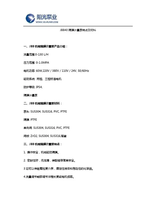
JBB40隔膜计量泵特点及材料
一、JBB机械隔膜计量泵产品介绍:
流量范围:0-130 L/H
压力范围: 0-1.0MPA
电机功率: 60W,220V / 380V / 110V / 24V, 50/60Hz
驱动系统: 两相、三相标准电机
防护等级: IP54,
隔膜计量泵
二、JBB机械隔膜计量泵材料:
泵头: SUS304, SUS316, PVC, PTFE
隔膜: PTFE
单向阀: SUS304, SUS316, PVC, PTFE
阀球: ZrO2, SUS304, SUS316,陶瓷
三、JBB机械隔膜计量泵特点:
1. 操作安全,机械驱动隔膜。
2. 密封性好,无泄漏,装配维修简单安全。
3.它可以传输高粘度介质,腐蚀性液体和危险性的化学品。
4.流量调节能够调节冲程长度或电机频率。
5.隔膜为多层复合结构压制而成,第一层超韧性Teflon耐酸薄膜,第二层EPDM弹性橡胶,第三层3.0mmSUS304支撑铁芯,手动试压泵第四层采用强化尼龙纤维补,第五层采用EPDM弹性橡胶完全包履,可有效提出升隔膜适用寿命。
四、JBB机械隔膜计量泵工作条件:
环境温度: -30℃--- 60℃。
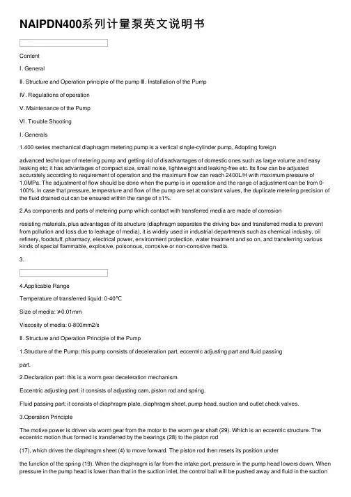
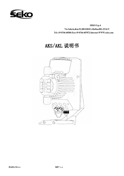
NAIPDN400系列计量泵英⽂说明书ContentⅠ. GeneralⅡ. Structure and Operation principle of the pump Ⅲ. Installation of the PumpⅣ. Regulations of operationⅤ. Maintenance of the PumpⅥ. Trouble ShootingⅠ. Generals1.400 series mechanical diaphragm metering pump is a vertical single-cylinder pump, Adopting foreignadvanced technique of metering pump and getting rid of disadvantages of domestic ones such as large volume and easy leaking etc; it has advantages of compact size, small noise, lightweight and leaking-free etc. Its flow can be adjusted accurately according to requirement of operation and the maximum flow can reach 2400L/H with maximum pressure of1.0MPa. The adjustment of flow should be done when the pump is in operation and the range of adjustment can be from 0-100%. In case that pressure, temperature and flow of the pump are set at constant values, the duplicate metering precision of the fluid drained out can be ensured within the range of ±1%.2.As components and parts of metering pump which contact with transferred media are made of corrosionresisting materials, plus advantages of its structure (diaphragm separates the driving box and transferred media to prevent from pollution and loss due to leakage of media), it is widely used in industrial departments such as chemical industry, oil refinery, foodstuff, pharmacy, electrical power, environment protection, water treatment and so on, and transferring various kinds of special flammable, explosive, poisonous, corrosive or non-corrosive media.3.4.Applicable RangeTemperature of transferred liquid: 0-40℃Size of media: ≯0.01mmViscosity of media: 0-800mm2/sⅡ. Structure and Operation Principle of the Pump1.Structure of the Pump: this pump consists of deceleration part, eccentric adjusting part and fluid passingpart.2.Declaration part: this is a worm gear deceleration mechanism.Eccentric adjusting part: it consists of adjusting cam, piston rod and spring.Fluid passing part: it consists of diaphragm plate, diaphragm sheet, pump head, suction and outlet check valves.3.Operation PrincipleThe motive power is driven via worm gear from the motor to the worm gear shaft (29). Which is an eccentric structure. The eccentric motion thus formed is transferred by the bearings (28) to the piston rod(17), which drives the diaphragm sheet (4) to move forward. The piston rod then resets its position underthe function of the spring (19). When the diaphragm is far from the intake port, pressure in the pump head lowers down. When pressure in the pump head is lower than that in the suction inlet, the control ball will be pushed away and fluid in the suctioninlet will flow into the pump head. When suction course is finished, pressure in the pump head is equal to the reset pressure of the control ball in the suction inlet. When the piston rod moves forward, the diaphragm pushes fluid to move forward and make pressure in the pump head increase up. When pressure is larger than that in discharge pipe, the control ball of the check valve on the discharge pipe is pushed away and fluid in the pump head will be drained to the discharge pipe, thus the pump head fulfills an suction-discharge course.. The flow adjustment of the pump is to change reset position of the piston rod by rotating adjusting cam (32) to change reciprocal distance of the diaphragm thus the flow is changed.Ⅲ. Installation of the Pump1.Installation size400-A Series400-C Series2.The pump should be located in an ambient temperature from -25 to 60℃, free air circulation isimportant when considering the location of the pump.3.The pump should be on a pedestal which is 300-500 meters above the surface, thus it can operate andcheck conveniently.4.All pipes to the pump should be supported to prevent stress on the pump input and output pipe. Beforeconnecting the pump, make sure that all pipes are completely cleaned by flushing, thoroughly. Any foreign matter entering the pump can damage the internal parts and severely limit the life of the pump.5. A “Y”strainer which can disassembly must be installed in the suction line of the pump to preventforeign matter entering the pump can damage the internal parts and severely limit the life of the pump.All joints of suction and discharge line to the pump should be sealed completely to prevent air from entering the pump.6.There should be no sharp turning on the suction and discharge pipes. Bending and joints of pipes shouldbe reduced as can as possible, and attachment which will increase the resistance of the pipe should also be reduced.7.Size of the suction pipe should be larger than the discharge pipe.8.Safety valves should be placed in the discharge pipes to insure the pumps operate safely. The operatingpressure of the safety valve should be 1.1 times as the rated discharge pressure of the pump. In order to decrease the pulsation of transferred liquid, a pulsation dampener should be placed in the discharge pipe near pump. Placed in the discharge piping near pump.Ⅳ. Regulations of OperationInitial operation1.Before starting a new pump, check all connecting bolts to see if they are tight. It is not allowed to haveany loosening. Check installation of pipes if they are correct, and check suction and discharge pipes if they are smooth.2.Fill 90# industrial gear oil in the tank, make the oil level at the middle of the oil mark.3.Before starting the pump, set the flow at zero and open all check valves on the suction and dischargepipes before adjusting the flow off zero.Operation of the pump1.In order to ensure that no air is in suction and discharge pipes of the pump, open the fluid filling systemfor the pump under the condition that no pressure is in the discharge pipe.2.For the new pump which is just putting into operation, check its operation condition and all movingparts should have no strong vibration and abnormal sound, otherwise stop the pump to find the reason and put into operation again when it is removed.3.After the first 12 operation hours, it should make check and calibrate over the pump so as to find exactflow under specified operation stare for later choice. Normally, the calibrating points are set at 100%, 50% and 0% of the flow.4.After the completion of operation, switch off power supply of the pump and stop operation of the motor.5.Close valves on suction and discharge pipes however they should be opened before next operation.6.Clear up dirty objects around the pump and keep the pump body clean.Adjust of operation stroke of the pumpBy rotating hand wheel (35) the operation stroke of the pump is adjusted. Make the hand wheel drive the Adjusting cam (32) to rotate and change the reset position of the piston rod to change reciprocal stroke of the diaphragm sheet so as to change the flow. The flow will be rising up when rotating the hand wheel clockwise and lowering down when rotating it counter-clockwise, and the range of adjustment is from 0 to 100%. Rotating the hand wheel every large division means to rising up or lowering down 10% of the range. When adjusting the hand wheel at set value of the flow, tight the knob (36) to avoid loosening during the course of moving. Should readjustment is needed, first loosen the knob and then rotate the hand wheel.Ⅴ. Maintenance of the Pump1.Mechanical lubrication oil shall be used in the driving case, and normally 50#—90# industrial gear oil isrecommended. Check quality of lubricating oil once every half a year and make frequent check over the reducer which is in long-term and continuous operation. Should deterioration or less viscosity of lubrication oil be found, it should be replaced on time. The term to change lubrication oil is as following2.Clean the strainer and suction and discharge valves regularly so as to avoid block and affect accuracy ofmeasurement. Be care of upper and lower seats when installing and never install upside down or incorrectly.3.Replace the diaphragm once every 4000 operating hours (or every six months). Replace ball, seat andO-ring of check valve once every six months. Should strong corrosive media be transferred, replacement should be more frequent.4.Should the pump be not in use for long time, drain off media inside the pump head and store the pumpwith the cover in a dry place.。
NPF 50 2” METALL I C PUMP (BOLTED )PWR-FLO TM A I R DI STR I BUT I ON SYSTEMO P E R A T I O N M A N U A LALUMINUM Models 316 S.S. ModelsAIR-OPERATED DOUBLE DIAPHRAGM PUMPSA JDA Global Company2CAUTION:Do not apply compressed air to theexhaust port – pump will not function.CAUTION: Do not over-lubricate air supply – excesslubrication will reduce pump performance. Pump ispre-lubed.TEMPERATURE LIMITS:Neoprene -17.7°C to 93.3°C 0°F to 200°FBuna-N -12.2°C to 82.2°C 10°F to 180°FEPDM -15.1°C to 137.8°C -60°F to 280°FNOTE: Not all materials are available for allmodels. Refer to Section 2 for material options foryour pump.CAUTION: Check temperature limits for all wettedcomponents. Example: Viton®has a maximumlimit of 176.7°C (350°F) but polypropylene has amaximum limit of only 79°C (175°F).CAUTION:Maximum temperature limit are basedupon mechanical stress only. Certain chemicalswill signi cantly reduce maximum safe operatingtemperatures.WARNING:Prevention of static parking – if staticsparking occurs, re or explosion could result.Pump, valves, and containers must be grounded toa proper grounding point when handling ammableuids and whenever discharge of static electricityis a hazard.CAUTION:Do not exceed 8.6 bar (125psig) airsupply pressure.CAUTION:The process uid and cleaning uidsmust be chemically compatible with all wettedpump components.CAUTION: Do not exceed 82°C (180°F) air inlettemperature.CAUTION:Pumps should be thoroughly ushedbefore installing into process lines.CAUTION:Always wear safety glasses whenoperating pump. If diaphragm rupture occurs,material being pumped may be forced out airexhaust.CAUTION:Before any maintenance or repair isattempted, the compressed air line to the pumpshould be disconnected and all air pressureallowed to bleed from pump. Disconnect all intake,discharge and air lines. Drain the pump by turningit upside down and allowing any uid to ow into asuitable container.CAUTION:Blow out air line for 10 to 20 secondsbefore attaching to pump to make sure all pipelinedebris is clear. Use an in-line air lter. A 5µ (micron)air lter is recommended.NOTE:When installing PTFE diaphragms, it isimportant to tighten outer pistons simultaneously(turning in opposite directions) to ensure a tight t.(See torque speci cations.)NOTE:Before starting disassembly, mark a linefrom each liquid chamber to its corresponding airchamber. This line will assist in proper alignmentduring reassembly.CAUTION:Tighten all hardware prior to installation.3XXX XX / XXXX / XX / XX / XXX / X / X / XNTG 50 / AAAB / TF / TF / ATF / N / C / XXXX XX / XXXX / XX / XX / XXX / X / X / X Viton Encap.41. Air ChamberThe air chamber is the chamber that houses the air which powers the diaphragms.2. Air Distribution SystemThe air distribution system is the heart of the pump. The air distribution system is the mechanism that shifts the pump in order to create suction and discharge strokes.3. Lock Nut (Outer Diaphragm Piston)The outer diaphragm pistons provide a means to connect the diaphragms to the reciprocating common shaft and to seal the liquid side from the air side of the diaphragm.4. Holding plate (Inner Diaphragm Piston)The inner piston is located on the air side of the pump and does not come into contact with the process uid.5. Check Valve BallNOMAD air-operated pumps use suction and discharge check valves to produce directional ow of process uid in the liquid chamber. The check valve balls seal and release on the check valve seats allowing for discharge and suction of process uid to occur.6. Check Valve SeatThe removable seats provide the ball valves a site to check.7. Discharge ManifoldProcess uid exits the pump from the discharge port located on the discharge manifold at the top of the pump.8. Liquid ChamberThe liquid chamber is lled with the process uid during the suction stroke and is emptied during the discharge stroke. It is separated from the compressed air by the diaphragms.9. DiaphragmThe diaphragm membrane provides for separation of the process uid and the compressed air power source. To perform adequately, diaphragms should be of suf cient thickness and of appropriate material to prevent degradation or permeation in speci c process uid applications. TABLA offers a variety of diaphragm materials for your speci c application requirements.10. Inlet ManifoldProcess uid enters the pump from the intake port located on the inlet manifold at the bottom of the pump.The NOMAD diaphragm pump is an air-operated, positive displacement, self-priming pump. These drawings show ow pattern through the pump upon its initial stroke. It is assumed the pump has no uid in it prior to its initial stroke.5Pump will not run or runs slowly.1. Ensure that the air inlet pressure is at least 0.4 Bar (5 psig) above start up pressure and that the differential pressure (the difference between air inlet and liquid discharge pressures) is not less than 0.7 Bar (10 psig).2. Check air inlet lter for debris3. Check for extreme air leakage (blow by) which would indicate worn seals/bores in the air valve.4. Disassemble pump and check for obstructions in the air passageway.5. Check for sticking ball check valves. If material being pumped is not compatible with pump, elastomer, swelling may occur. Replace ball check valves and seals with proper elastomers. Also, as the check valve balls wear out, they become smaller and can become stuck in the seats. In this case, replace balls and seats.6. Check for broken inner piston which will cause the air valve spool to be unable to shift.7. Remove plug from pilot spool exhaust.Pump runs but little or no product flows.1. Check for pump cavitation; slow pump speed down to allow thick material to ow into liquid chambers.2. Verify that vacuum required to lift is not greater than the vapor pressure of the material being pumped (cavitation).3. Check for sticking ball valves. If material being pumped is not compatible with pump elastomers, swelling may occur. Replace ball check valves and seats with proper elastomers. Also, as the check valve balls wear out, they become smaller and can become stuck in the seats. In this case, replace balls and seats.Pump air valve freezes.1. Check for excessive moisture in compressed air. Either install a dryer or hot air generator for compressed air. Alternatively, a coalescing lter may be used to remove the water from the compressed air in some applications.Air bubbles in pump discharge.1. Check for ruptured diaphragm.2. Check tightness of outer pistons.3. Check tightness of fasteners and integrity of o-rings and seals, especially at intake manifold.4. Ensure pipe connections are airtightProduct comes out air exhaust.1. Check for diaphragm rupture.2. Check tightness of outer pistons to shaft.Troubleshooting6INSTALLATION:• Suction pipe equal to/greater than pump diameter (same for discharge)• Tighten all fasteners before use• Suction connection should be non-collapsibleAIR SUPPLY:• Air line size must be large enough to create desired volume (see performance curve section)• Do not exceed 8.6 BAR (125 PSIG)• For best results, use 5 micron air lter • Use lubricator with 5 wt. oilPIPING:• Remove as many turns/elbows as possible • Piping should be supported• Flexible hose will avoid stress on pump tting • Gate Valve should be used in applications involving ooded suction • In positive suction head conditions, limit inlet pressure to 0.5 - 0.7 BAR (7 - 10 PSI). Premature diaphragm failure will take place above the parameters.ALL NOMAD PUMPS ARE CAPABLE OF PASSING SOLIDS. A STRAINER SHOULD BE USED ON THE PUMP INTAKE TO ENSURE THAT THE PUMP’S RATED SOLIDS CAPACITY IS NOT EXCEEDED.CAUTION: DO NOT EXCEED 8.6 BAR (125 PSIG) AIR SUPPLY PRESSURE.7This illustration is a genericrepresentation of an air-operated double-diaphragm pump.NOTE: In the event of a power failure, the shut off valve should beclosed, if the restarting of the pump is not desirable once power is regained.AIR OPERATED PUMPS: To stop the pump from operating in anemergency situation, simply shut off valve (user supplied) installedin the air supply line. A properly functioning valve will stop the air supply to the pump, therefore stopping output. The shut off valve should be located far enough away from the pumping equipment such that it can be reached safely in an emergency situation.DIMENSIONSITEMMETRIC (mm)STANDARD (inch)A 43917.3B893.5C 39615.6D 67626.6E 76029.9F943.7G 117 4.6H 32512.8J 49319.4K 39615.6L 33013.0M 25410.0N 32512.8P 37914.9R150.6DIMENSIONSITEM METRIC (mm)STANDARD (inch)A 43417.1B893.5C 38915.3D 67826.7E 76029.9F943.7G 117 4.6H 32512.8J 49319.4K 39115.4L 33013.0M 25410.0N 32512.8P 37914.9R150.6METRIC (mm)STANDARD (inch)A43917.3B893.5C 39615.6D67626.6E 76029.9F943.7G 1174.6H 32512.8J 49319.4K 39615.6L 33013.0M 25410.0N 32512.8P 37914.9R150.6ITEM METRIC (mm)STANDARD (inch)A 43417.1B893.5C 38915.3D 67826.7E 76029.9F943.7G 117 4.6H 32512.8J 49319.4K 39115.4L 33013.0M 25410.0N 32512.8P 37914.9R150.6METRIC (mm)STANDARD (inch)A 43917.3B893.5C 39615.6D 67626.6E 76029.9F943.7G 117 4.6H 32512.8J 49319.4K 39615.6L 33013.0M 25410.0N 32512.8P 37914.9R150.6ITEM METRIC (mm)STANDARD (inch)A 43417.1B893.5C 38915.3D 67826.7E 76029.9F943.7G 117 4.6H 32512.8J 49319.4K 39115.4L 33013.0M 25410.0N 32512.8P 37914.9R150.6METRIC (mm)STANDARD (inch)A 43917.3B893.5C 39615.6D 67626.6E 76029.9F943.7G 117 4.6H 32512.8J 49319.4K 39615.6L 33013.0M 25410.0N 32512.8P 37914.9R150.6METRIC (mm)STANDARD (inch)A 43917.3B893.5C 39615.6D 67626.6E 76029.9F943.7G 117 4.6H 32512.8J 49319.4K 39615.6L 33013.0M 25410.0N 32512.8P 37914.9R150.6METRIC (mm)STANDARD (inch)A 43917.3B893.5C 39615.6D 67626.6E 76029.9F943.7G 117 4.6H 32512.8J 49319.4K 39615.6L 33013.0M 25410.0N 32512.8P 37914.9R150.69Flow rates indicated on chart were de termined by pum ping wa ter.For optimu m life an d performa nce, pum ps s hould be s pecified s o that daily operation param eters will fall in the center of the pum p's performa nce curve.agains t a disc ha rge head of 2.7 bar (40 ps ig) requires 4.1 bar (60 ps ig) and 92 N m 3/h (54 s cfm ) air cons um ption. C aution: Do not exceed 8.6 bar (125 ps ig) air s upply pres s ure.Flow rates indicated on chart were de termined by pum ping wa ter.For optimu m life an d performa nce, pum ps s hould be s pecified s o that daily operation param eters will fall in the center of the pum p's performa nce curve.agains t a dis charge head of 4.8 bar (70 ps ig) requires 5.5 bar (80 ps ig) and 75 N mC aution: Do not exceed 8.6 bar (125 ps ig) air s upply pres s ure.NPF 50 BOLTED Aluminum*Consult Elastomer Options10NPF 50 BOLTED Stainless Steel*Consult Elastomer Options2”CENTRE P I ECE W I TH A I R V AL V E ASSEMBLY。
1.上海阳光泵业制造有限公司上海阳光泵业制造有限公司系上海水泵生产厂家之一,专门研制各种水泵产品,广泛应用于水利、建筑、消防、电力,环保、石油、化工等各个领域,受到各行用户的好评!上海阳光泵业把先进的技术与多年实践经验的完美结合,水泵产品高效能、可靠耐用,完善的售前售中售后服务是赢得市场的搏击点。
水泵产品的优良品质,是为了满足专业需求而特殊设计的。
上海阳光泵业完美的水泵产品具备进口的质量,只有国产的价格。
良水泵致力于“素质、优质、品质,实质”的企业理念,以用户满意为目标。
打品牌战略,走科技之路,创造二十一世纪新的辉煌!2 .威乐:威乐(Wilo)总部位于德国的多特蒙德,是全球领先的水泵和水泵系统制造商之一。
公司于1872 年成立,当时只是一家铜和黄铜制品厂,历经了140 多年的发展。
企业精神是“同心、进取、创新、卓越”,我们期待着更多拥有梦想、敢于拼搏的人,创造属于你我的辉煌!3.赛高:SEKO品牌是一家全球闻名的加药泵和系统制造企业,已有40多年历史。
从卫生和表面清洁系统设计到人类消费、冷却塔、泳池和各类工业流程所需的水处理,SEKO专注于电磁和电机驱动加药泵、测量和分析仪表的专业设计与制造,可根据任何需求量身定制解决方案.4.河北省泊头市亿力泵业是生产齿轮泵的专业厂家。
公司成立多年来已形成完备的工业泵生产体系。
目前生产的热油泵、稠油泵、不锈钢齿轮泵、圆弧泵及KCB、2CY全系列多品种优质泵,产品齐全行销国内外,为国家石油、化工、电力、造船、食品、橡胶等企业提供了数量可观的优质产品,赢得了各行业的好评。
5.泊头市鸿海泵业有限公司是以开发、制造各种齿轮泵、导热油泵、容积泵、不锈钢泵、离心泵、螺杆泵为主的专业生产厂家,具有完善的生产体系和质量保证体系。
产品广泛应用于国家石油、化工、船舶、电力、粮油、建材、冶金、国防及科研等行业,并有部分产品销往国际市场。
主要产品有KCB、2CY型输油泵,KCB型铜轮泵,RY型高温热油泵,BCB型摆线内啮合燃油泵,ZYB 型渣油泵,NYP型稠油泵,BWB型保温泵,CB-B型齿轮泵,CYZ型自吸式离心油泵,BRY型离心式高温热油泵,YHB型立、卧式润滑齿轮泵,三螺杆泵,焦油专用泵,电动齿轮泵等十五大系列300多种规格,规格齐全,适用范围广。
TRATTAMENTO DELLE ACQUER egolazione della pompaMixRiteIl volume di iniezione viene impostato manualmente ruotando la ghiera nella proporzione desiderata. La quantità di prodotto concentrato iniettato è proporzionale alla quantità di acqua che scorre nella pompaMixRite.Acqua dolceManicottoregolazionedosaggioMotoremiscelatoreTefen dal 1973 è leader nella produzione di miscelatori volumetrici che nonrichiedono energia elettrica per il loro funzionamento e che rispettano l’ambiente.La linea di pompe dosatrici MixRite di Tefen garantisce una precisamiscelazione del prodotto concentrato nella rete idrica o di altri liquidi.È la scelta giusta per molti motivi.Applicazioni■Clorazione■Igienizzazione■Disinfezione dell’acquaLa pompa dosatrice azionata ad acqua MixRite di Tefen è un sistemafacile da usare e ingegnoso che ha dimostrato il suo valore in oltre 90paesi.Tefen è certificata ISO 9001 2015T asso di dosaggioInformazioni su TEFENVantaggi dell’utilizzo di MixRite■Facile installazione■Bassi costi di esercizio e manutenzione■Motore idraulico attivato solo dalla pressione del flusso dell’acqua –non elettrico■Dosaggio proporzionale alla portata■Ripetibilità e omogeneità del dosaggio eccellenti2 | POMPE DOSATRICIClorazione per zone rurali o in casi di emergenza:■Si stima che 2,6 miliardi di persone non abbiano un accesso soddisfacente all’acqua potabile■adatte a condizioni estreme, come la mancanza di elettricità e di vincoli locali■Concentrazione e dosaggio tipici:■Ipoclorito di sodio: 0,3 - 5 PPM■Biossido di cloro: 0,3 – 5 PPM■Perossido di idrogeno: 1 PPM e superiore■Tutti i livelli di concentrazione e dosaggio si riferiscono al contenuto di acqua.Controllo del PH■Per il controllo del pH vi è una vasta gamma di acidi utilizzati, come ad esempio: acido solforico, acido clorico, acido fosforico, acido nitricoIgienizzazione e disinfezioneLe pompe dosatrici proporzionali MixRite sono ampiamente utilizzate per l’igienizzazione e la disinfezione delle reti idriche.Settori che rientrano in questa applicazione:■Trasformazione e igienizzazione dei prodotti agroalimentari■Pulizia delle linee di produzione della birra■Sale operatorie – pulizia e disinfezione delle superfici■Additivi detergenti e igienizzanti da dosare e iniettare, inclusi glutaraldeide e acidi organici come:■acido peracetico, acido formico, ecc.■ammonio quaternario, ecc.ClorazioneProdotti chimici e acidi PVDF34 | POMPE DOSATRICIPompe dosatriciPressione dell’acqua 0,2 – 8 bar Portata 10 – 3.500 L/h Peso 1,8 kg*Attacco3/4”0,03-0,2%, 0,1-0,9%, 0,3-2%, 0,5-5%, 1-10%Pressione dell’acqua 0,2 – 8 bar Portata 7 – 2.500 L/h Peso 1,8 kg Attacco3/4”Portata bassa0,1-0,9%, 0,3-2%, 0,4-4%Pressione dell’acqua 1 – 8 bar Portata 0,05 - 10 m 3/h Peso 7,4 kg Attacco1,5” o 50 mm* Gambe di supporto disponibili su richiesta speciale0,1-1%, 0,2-2%, 1-5%Pressione dell’acqua 1 – 8 bar Portata 0,02 - 5 m 3/h Peso 5 kg Attacco1” o 32 mm* Gambe di supporto disponibili su richiesta speciale0,1-1%, 0,2-2%, 0,5-5%*1-10%: 3 kg5Purificazione dell’acqua potabile6 | POMPE DOSATRICISistema galleggiante percisterne Watch Guard e iniettori ad acqua MixRiteWatch Guard è il primo sistema di diluzione con valvola galleggiante per cisterne progettato per la fornitura di soluzioni diluite in qualsiasi fusto, cisterna o altro tipo di serbatoio. Quando viene collegato ad una fonte idrica standard, Watch Guard si attiva automaticamente e tiene il serbatoio pieno, garantendo una fornitura costante di soluzione diluita per il sistema MixRite.Gli iniettori ad acqua MixRite si collegano in linea alla rete idrica e utilizzano la pressione dell’acqua p e r m i s c e l a r e a c c u r a t a m e n t e l e s o l u z i o n i indipendentemente dalle variazioni di flusso o di pressione.Utilizzando Watch Guard in combinazione con qualsiasi sistema MixRite è possibile ottenere diluzioni elevate, fino a 5 parti per milione.■Consente di ottenere una diluzione elevata in 2 semplici passi■delle sostanze chimiche■Watch Guard è semplice da installare su qualsiasi fusto, cisterna o altro serbatoio■Si attiva automaticamente per mantenere il serbatoio pieno di soluzione miscelata■Punta di misurazione inclusa per le diluzioni da 0,25% a 14,2%■Comprende un dispositivo di ritegno per i divari di azione approvato ASSE 1055B■MixRite si collega in linea alla rete idrica■Fornisce un dosaggio accurato indipendentemente dal flusso d’acqua o dalle variazioni di pressione ■Diversi modelli disponibili per volumi di dosaggio dall’1% al 10% e portate d’acqua da 227 a 25.000 litri all’oraDiluzioni elevateMixRite+=AcquaDiluzione fino a 5 PPMDiluzione 0,25%-14,2%AcquaQualsiasi acido concentrato, cloro o sostanza chimicaDA NON SCALARE(Serbatoio per la soluzione diluita)PUNTA DI MISURAZIONE7Rapporti di induzione per le viscosità mostrateRapporti di diluzione di MixRite in combinazione con l’unità Watch Guard8 | POMPE DOSATRICISistema di bypass proporzionale e automaticoIl sistema TreatRite™ fornisce un metodo proporzionale tra la linea principale (A) e la sotto-linea (B), supportato da un sofisticato sistema idraulico innovativo. La pompa MixRite™ è un’unità volumetrica proporzionale. La combinazione di pompa dosatrice MixRite™ e unità bypass crea un sistema di dosaggio completamente proporzionale. Questo sistema fornisce pertanto all’utente una soluzione perfetta per il trattamento delle acque. L’utente finale del sistema TreatRite™ può dosare i comuni additivi per il trattamento delle acque, come ad esempio: ipoclorito di sodio, biossido di cloro e perossido di idrogeno. Il sistema TreatRite™ può essere utilizzato a diversi intervalli, come riportato qui di seguito:– Linea di trattamento delle acquePerdita di pressione vs. portata5,00,000,400,801,201,6015,025,035,045,055,065,075,085,095,0P e r d i t a d i p r e s s i o n e (b a r )Portata della linea principale (m 3/h)2"3"4"AB90%10%9Gamma :Principio di funzionamento■La valvola di comando pilota rileva il livello dipressione in più punti e controlla la condizione di apertura del diaframma.■Questa operazione regola le portate per generare un rapporto stabile 1:10 tra le linee.Caso di studio (trattamento delle acque)■Portata totale dell’acqua: 67,3 m 3/h ■Tasso di dosaggio desiderato: 0,1%■Quantità dell’additivo: 67,3 x 0,1% = 0,0673 m 3/h Configurazione rilevante: 4’’, 1,5"■Flusso dell’acqua della linea principale: 67,3 x 0,9 = 60,57 m 3/h■Flusso dell'acqua del bypass: 67,3 x 0,1 = 6,73 m 3/h Iniettore rilevante: TF10 0,2%-2%■Impostazione del dosaggio sull’iniettore: 0,0673 / 6,73 = 1%Caratteristiche e vantaggi■Mantiene costante la portata proporzionale ■Idraulico, volumetrico e non elettrico ■Dosaggio proporzionale alla portata■Precisione: qualità in superficie ottimizzata, senza sprechi■Ad ampie portate, la portata tra la linea principale e la linea secondaria rimane 10:1 ■Pressione operativa fino a 8 bar ■Elevata resistenza ai raggi UV ■Elevata resistenza chimica■Sistema preimpostato. Nessuna calibrazione necessaria■Ripetibilità e omogeneità del dosaggio eccellenti■Di facile installazione, utilizzo e manutenzione, senza rischi elettriciTF-52.53.5TF-10Trattamento delle acqueCon trattamento delle acque si intende qualsiasiprocesso volto a migliorare la qualità dell’acqua perrenderla più idonea a uno specifico uso finale. L’usofinale può essere: produzione di acqua potabile,fornitura di acqua a uso industriale, irrigazione,manutenzione dei flussi fluviali, ricreazione delle acquee molti altri usi, compresa la reimmissione sicuranell’ambiente.Tefen Flow Products è uno dei principali fornitori diprodotti per tubazioni industriali a livello mondialeper soddisfare le esigenze di impianti idrici e didepurazione. Il sistema di Tefen, superiore allaconcorrenza, è composto da raccordi, valvole e tubie garantisce prestazioni uniformi in tutti gli impianti ditrattamento Le proprietà non corrosive garantisconobuone prestazioni sul lungo periodo e bassi costi dimanutenzioneI prodotti Tefen Flow sono certificati NSF e hannoconseguito l’approvazione WRAS.10 | POMPE DOSATRICI11RACCORDI IN PVDFPRE-FILTRO DELL’ACQUAVALVOLETEFEN LTD.KibbutzNahsholim3081500Israele|Tel.97246395944|Fax.97246390813|********************| E D I T I O N 0 4 I T 0 4 / 2 0 2 0 n o w -b r a n d i n g . c o . i le/o le specifiche tecniche dei prodotti e/o aggiungere e/o rimuovere prodotti e/o modificare i prezzi e/o i termini e le condizioni specificati nel presente documento in qualsiasi momento e a sua esclusiva discrezione, senza alcun preavviso.。
米顿罗计量泵安全操作及保养规程引言米顿罗计量泵作为化学工业生产中常用的装置之一,其正常运行对工厂的生产效率和安全性都至关重要。
因此,在使用米顿罗计量泵之前,必须要了解其安全操作和保养规程,以确保其安全可靠地运行。
本文将介绍米顿罗计量泵的安全操作和保养规程。
安全操作规程1. 操作前检查在使用米顿罗计量泵之前,必须进行全面的检查,以确保设备正常运行且无故障。
•检查所有管道是否正确连接和紧固;•检查管道是否有泄漏现象;•检查计量泵的密封件是否正常,是否需要更换或紧固;•检查泵的排放压力,是否与需要的操作压力一致;•确保阀门的位置和状态正确,未误操作或损坏。
如果发现任何问题,必须在我们的维修人员的帮助下解决问题并确认设备正常运行后再进行操作。
2. 操作中注意事项在使用米顿罗计量泵的过程中,必须注意以下事项:•严格按照操作程序执行,切勿随意更改操作流程;•根据孔板压差进行排放控制;•在泵排放结束后,必须保证泵内部压力已降至零,并关闭阀门;•如果需要翻新或维修计量泵,必须先向设备制造商或专业化修理公司请教,并严格按照他们的推荐程序进行。
3. 关机后的清洗和日常保养在计量泵使用完毕之后,必须进行清洗和维护,以延长设备的使用寿命。
•使用合适的清洁剂对设备进行清洗;•每隔一段时间(通常为3个月)对设备实施维护,清理泵内积淀的污垢,检查设备各部位的磨损情况,并进行必要的更换或维修。
保养规程1. 每日保养在每日保养中,应对米顿罗计量泵进行以下维护:•进行设备清洗,清除进出口道的泥沙和造成堵塞的杂质;•检查所有管道和管件是否磨损或者开裂,发现问题及时更换;•调整设备,确保其稳定运行。
2. 每周保养在每周保养中,应对米顿罗计量泵进行以下维护:•拆开泵,检查各部件是否有磨损、变形等问题,并进行必要的更换;•检查阀门密封情况,并进行必要的调整和更换。
3. 每月保养在每月保养中,应对米顿罗计量泵进行以下维护:•对所有零部件进行测试,确保其正常运行和操作;•清理整个设备,防止阻塞或损坏。
计量泵十大品牌合集泵业前10强排名1.上海沈泉泵阀制造有限公司上海沈泉泵阀制造有限公司是一家专业生产,销售管道泵,排污泵,消防泵,化工泵等给排水设备的厂家,产品涉及工矿企业、农业、城市供水、石油化工、电站、船舶、冶金、高层建筑、消防供水、工业水处理和纯净水、食品、制药、锅炉、空调循环系统等行业领域。
2. 新疆百利万通机电设备有限公司新疆百利万通机电设备有限公司成立于2018年,位于乌鲁木齐市星河水泵市场及恒汇机电城主要经营:水泵,滴灌泵,管道泵,多级泵,渣浆泵,压滤机入料泵,双吸泵,离心泵,潜水泵,深井泵,污水泵,化工泵,无塔供水设备吗,广泛应用于生活给水,农用排灌、化工、制药、造纸、石油、采矿、建筑、冶金、消防等各行各业。
3. 湖南中开泵业有限公司湖南中开泵业有限公司(中开泵业、中泵、长泵特泵、汨罗制泵)是长沙水泵行业知名水泵制造厂家,注册商标“长一制泵”,长沙水泵厂始建于1951年,曾用名称长沙通大集团长沙水泵厂,长沙工业泵总厂,长沙天鹅工业泵厂,于1951年正式建厂,多年来一直从是国内知名的专业中开泵-多级泵-双吸泵-立式斜流泵-冷凝泵-凝结水泵-立式长轴泵-清水泵-船用挖砂泵等泵类设计、研发和生产的综合泵业公司。
4. 四川三台力达泵业有限公司四川三台力达泵业有限公司,成立于1995年,现座落于三台县青东坝工业集中区四号路;注册资本2000万元,拥有资产1.2亿余元,员工130余人,其中中高级专业技术管理人员40余人。
公司厂区占地面积80余亩,包括办公大楼、生产车间、职工宿舍、活动中心等建筑。
具有模具制造、铸锻件生产、理化检验、机械加工、装配、测试的完整泵制造体系。
有各类主要设备200余台(套),其中包括大型立车、铣床、龙门刨、抛丸机、新型造型机、1.5吨中频炉、600吨液压机、自动测试台架、大型清洗机等在内的重点设备达30余台(套)。
年生产能力20000余台,大口径可达1m,能生产制造灰铸铁、球墨铸铁、不锈钢、高分子材料等众多材质的产品。
计量泵安装在进料罐的支座上是最好的安装方式,吸入管线始终被料液充满。
因此,在每天只用几个小时的场合下,此种安装方式最适宜。
安装时只可用手紧固,切不可使用工具。
料液的注入:将料液加入敞口容器。
每台计量泵在出厂时均带有防虹吸弹簧,该弹簧装在泵的出口处,可以防止由于大气压力而引起的料液倒流,还可以起到泵出口处的密封作用。
*防虹吸阀如果可能发生虹吸现象,应在计量泵的出口处安装防虹吸阀,以此代替计量泵的出口阀。
在拆卸出口阀时,应注意不要丢失诸如阀内的小球、垫片等小零件。
防虹吸阀不是100系列计量泵的标准配件,如用户需要,需另外付款购买。
*料液的注入点如果化学料液在注入点处不能迅速地稀释,可能在注入点处造成管线的腐蚀。
只要将进料管的末端接入流动的管线中即可。
*计量泵安装中的注意事项化学料液由三通管加入系统时,不要将进料管的末端从上垂直接入系统或水平接入系统,否则可能造成管线的腐蚀或结垢。
计量泵的最高安装尺寸为1.5米;安装完毕之后,所有的箭头均应指向上方。
启动隔膜式化学计量泵:*电源计量泵的电压为230伏,频率50赫兹。
*计量泵的试运转所有的计量泵在出厂时均用水进行了试运转,如果输送的料液与水混合时会发生化学反应(如硫酸),则应在使用前将泵头拆开,彻底干燥隔膜及阀座,然后投入使用。
如果料液需注入到带压系统内,那么在试运转时,应先将泵的出料管暂时拆下来,接通电源后,逆时针旋松锁紧手柄,将输出调节钮按逆时针调至最大,然后锁紧该手柄。
几分钟后,料液将被送至泵头。
注意:计量泵运行时可以调节泵的流量,但不可用力旋转表盘。
如果几分钟后,料液未能送至泵头,则应将出口组件拆下来,将料液灌入泵体,复位后再启动计量泵。
操作时应配带防护手套和防护眼镜。
一旦计量泵试运转完毕,应切断电源,将各组件拆下来,并立即清洗残留的料液,然后将计量泵的输出调节钮调至工作位置。
如不将拆卸计量泵的出口组件,也可以使用回流管线试泵。
耐普顿计量泵
普顿计量泵型号确定计量泵的规格:
确定计量泵的规格,首先包括其流量和出口压力。
不要使用规格过大的泵。
一般而言,计量泵的大小应该是其预计的最大流量为泵的额定流量的85%至90%,这样留下一些额外的容量在需要
时可用。
其最小流量不应小于计量泵额定流量的10%以确保泵的精确性。
其次要考虑泵的材质,计量泵采用多种材质。
选择时需考虑腐蚀、侵蚀、溶剂作用。
含溶剂的化学品会溶解塑料美国Neptune耐普顿计量泵型号
泵头;酸性和碱性的化学品则要求使用不锈钢或合金制造的液相部件。
在输送具有磨蚀性的浆料时,需要考虑磨蚀作用。
美国Neptune机械隔膜泵总代理
化学品的粘度如何?
是不是浆料?会不会释放出气体?针对这些特殊的应用,需要采用特殊的液相部件。
标准的计量泵可以输送粘度如水一样到1500cPs的纯液。
特殊的液相部件可以输送粘度高达5000cPs的液体和轻度悬浊液。
详情请向工厂咨询。
本公司是意大利SEKO计量泵公司授权江苏一级代理。
公司代理经销美国米顿罗计量泵,美国帕斯菲达计量泵,德国普罗名特计量泵,格兰富ALLDOS计量泵,意大利爱米克EMEC计量泵,DOSEURO道茨计量泵,OBL计量泵,日本日机装NIKKISO,易威奇IWAKI计量泵,国产爱力浦AILIPU计量泵等各种品牌各种规格计量泵。
海王星neptune化工泵代理
同时经销格GF SIGNET仪表,兰富水泵,美国胜佰德气动隔膜泵,反渗透膜等水处理系统材料的供应。
7000系列机械隔膜计量泵
特性美国Neptune耐普顿计量泵型号
• 标准计量泵可以输送水样澄清液体至粘度为1,500 cPs的液体• 泵在运行机时,也可以通过千分级旋钮调节流量
技术数据
• 过流材质:PVC• 马达数据:整体马达,可选D法兰(IEC)和(NEMA)C法兰• 马达选项:防爆、可清洗、变频驱动
性能数据美国Neptune耐普顿计量泵厂家
• 流量@ 60Hz:10 gph(38 lph)至450 gph(1,710 lph)
• 流量@ 50Hz:8 gph(30 lph)至375 gph(1,400 lph)
• 最大压力:150PSI(10BAR)
应用领域美国Neptune耐普顿计量泵型号
• 农业• 化学加料• 化学加工• 化学灌溉• 滴灌• 气体脱臭
认证和行业组织• 工业• 采矿• 市政水处理• 市政废水处理• 发电• 加工工艺Series 7000 公司研发的机械驱动隔膜计量泵和液压驱动隔膜计量泵早已成为在水/废水处理、灌溉、化工工艺、发电、石油天然气、石化以及其他工业市场中的化学剂加注应用的标准。