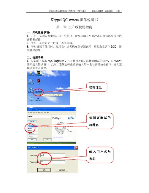
扬声器测试Klippel 操作方法
- 格式:doc
- 大小:874.50 KB
- 文档页数:6
扬声器的主要技术参数及测量方法一、极性1、极性标志扬声器输入端的极性标志是指在扬声器输入端馈入信号时,扬声器膜片产生运行的方向与输入端所加信号极性之间关系的标志。
2、测量方法按规定馈给扬声器以瞬时直流电压,引起膜片向扬声器前方运行时,与电压正极相连接的输入端为扬声器正极,用红色或符号:“+”表示。
二、纯音检听1、特性解释在额定频率范围内,馈给扬声器以规定电压的正弦信号,检查扬声器的装配质量。
2、测量方法(1、)扬声器单元检听馈给扬声器正弦信号的电功率为二分之一额定噪声功率:U= WRn/2,一般在0.3m处检听,在此距离内应无反射物(试听室)。
扬声器单元不另加负载。
注:A、全频带及低频扬声器检听时,应从共振频率允许偏差下限向高频扫频。
B、中频、高频扬声器检听时,应从分频点频率开始向高频扫频。
C、高顺性扬声器检听时,可以在产品标准规定的声负载上进行。
应从共振频率允许偏差下限开始向高频扫频。
D、为便于检查垃圾声、碰圈声和机械声,在共振频率Fo附近必须检听,但可以规定馈给扬声器以较低的信号电压。
2 、扬声器系统检听馈给扬声器系统的正弦信号电压及检听距离由标准规定。
检听时由系统的下限频率开始向高频扫频,有衰减器时,一般将衰减器置于频率响应的平直位置或产品标准规定的位置。
三、额定阻抗扬声器的额定阻抗是一个由制造厂规定的纯电阻值,在确定信号源的有效电动率时,用它来代替扬声器。
额定阻抗是指阻抗曲线上紧跟在第一个极大值后面的极小值。
在额定频率范围内,阻抗模值的最低值一般不应小额定阻抗的80%(一般取±20%公差,例8±20%Ω)。
上面提到阻抗曲线----把阻抗值表示为频率的函数。
(如下图)额定阻抗的测试方法:用替代法进行,馈给扬声器的电流通常选用50mA±10%,测量原理图如下:测量时开关K先接通被测扬声器。
在扬声器辐射面前0.3m内应无反射物。
递增信号频率,若无其它规定,使频率停留在有效值电压表指示的第一个极大值后面的极小值处,然后将开关K接通Rk并调节电阻Rk,当电阻Rk上的电压与被测扬声器上的电压一致时,所指示的Rk值即可用于判定是否符合额定阻抗规定的要求。
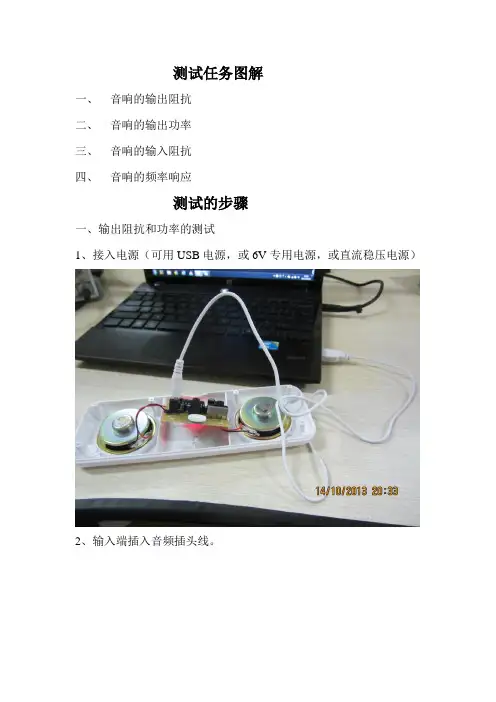
测试任务图解一、音响的输出阻抗二、音响的输出功率三、音响的输入阻抗四、音响的频率响应测试的步骤一、输出阻抗和功率的测试1、接入电源(可用USB电源,或6V专用电源,或直流稳压电源)2、输入端插入音频插头线。
3、将音量电位器开到最小。
4、函数信号发生器输出1KHZ,900mV正弦信号,加入右通道输入端。
5、示波器和交流毫伏表,接入右通道的喇叭两端,注意极性。
6、逐步开大音量电位器,观测示波器的波形不失真为止。
7、记下毫伏表所示的输出电压U L 。
示波器毫伏表8、断开喇叭正端,重新测输出电压U O 。
将数据填入下表:示波器毫伏表L O L O R V V R ∙⎪⎪⎭⎫ ⎝⎛-=1S断开时V O 值 接入RL时的V L 值RL=4ΩR O计算值Po=V L 2 /R L二、输入阻抗的测试: 9、输入端串入22K 电阻。
10、原弦信号从电阻一端输入,将毫伏表测信号源输出电压记录数值U S。
信号源毫伏表11、将毫伏表测电路输入端电压记录数值U i。
信号源毫伏表将数据记录下表:i is i V R R V V =∙-' , 50 1.7865022i i i R R R ⨯==⨯-’’信号源输出电压V S 值电路输入端电压V i ( R=22 k Ω)R i 计算值三、频率响应的测试:12、使信号源的频率从10HZ 到1MHZ 变化,得出幅频特性曲线。
四、总结:f (Hz )1050 100 1K 5K 10K 50K100K 1M 输入电压Vi (mV )输出电压Vo (V )O iV A V更改频率值,依次测量10Hz 到5MHz 输入信号时,对应的输出幅值。
斯贝克电子(嘉善)有限公司扬声器阻抗测试操作规程一.抽样要求每批成品中抽取3只来测试。
具体抽取方法为每做完总数的三分之一中抽取一只,直至抽完3只。
二.测试1.先开启测试系统,把信号输出接至扬声器接线板上(双头扬声器,接线板需串联)2.红色夹子接正极,黑色夹子接负极。
3.拨动开关位置:左边---1#4.将待测扬声器放在对应木板的孔中这样可以使上下声场的扩散面积增大,对曲线影响降至最小,然后张开双手五指,轻按扬声器音盆数下在缓缓抬起,使之后所测得的参数与实际更接近;注意用力,以免损坏扬声器。
5.双击DAAS M32—Ⅱ打开测试程序,点击Measvrementes菜单下的子菜单Thiele small parameter出现一线路图后,点击F1 Start Reference Meas然后用双手按住扬声器盆架边缘,等听完扬声器振动声后,点击F1 OK,并将左边拨动开关拨到2#,点击F1 Start,再用双手按住盆架边缘,扬声器振动完后点击F1 OK并点击Change,输入被测扬声器的直流电阻并点击OK(由于扬声器电阻受温度影响较大,一般将室温控制在[18-22]度之间,要是将仰声器从温度较低或较高的地方拿进室中,应在室中放置2小时或2小时以上)。
6.当扬声器的Mns>250克时,应使用密闭式箱体测试法测试阻抗曲线:首先,将扬声器放置于测试台的测试孔中取得第一条曲线(按第4条测试)然后将扬声器倒置于一个密闭木箱上面向下,封闭性良好,在测试之前应测量出整个封闭箱的有效容积,箱体孔的体积和扬声器音盆的有效容积并把三者之和输入电脑提示的0-200L的表格内箱体的体积与曲线的关系为:体积越大所测出的两条曲线越接近。
值得注意的是用密闭式箱体测试法时,不可能出现无法测得的数据,此时如还出现不正常的现象说明扬声器本身技术上有问题7.用天平称取合适的橡皮泥(按Mns对照表)做成粗细相同的圆环加至防生罩与音盆的粘接处并用双手轻按橡皮泥,使之与防生罩紧紧粘住不能松动使音盆四周受到相同的力,然后先点击F2 V AS 后点击F1 Repecet,同样双手按住扬声器盆架边缘,振动完后再次点击OK,在对话框中输入扬声器泡沫边的有效振动直径并点击OK,再输入橡皮泥的重量并点击OK出现测试所要的曲线,并使曲线在整个屏幕显示最大。
扬声器力学分布式参数第二部分:诊断篇WOLFGANG KLIPPELAES MemberUniversity of Technology Dresden,Dresden, GermanyJOACHIM SCHLECHTERKlippel GmbH, Dresden, Germany译者:王刚平Distributed mechanical parameters describe the vibration and geometry of the sound- radiating surface of loudspeaker drive units. These data are the basis for predicting the sound pressure output and a decomposition of the total vibration into modal and sound pressure–related components. This analysis separates acoustical from mechanical problems, shows the relationship to the geometry and material properties, and gives indications for practical improvement. A new kind of loudspeaker diagnostic becomes possible, and a step-by-step methodology is developed. Common problems are discussed in relation to design choices.力学分布式参数描述了扬声器单元的振动与声辐射面之间的关系。
这些参数是预测声压输出和把总的振动分解成不同模态或是与声压有关的分量的基础。
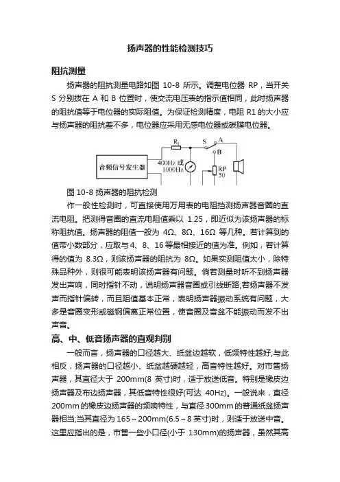
扬声器的性能检测技巧阻抗测量扬声器的阻抗测量电路如图10-8所示。
调整电位器RP,当开关S分别拨在A和B位置时,使交流电压表的指示值相同,此时扬声器的阻抗值等于电位器的实际阻值。
为保证检测精度,电阻 R1的大小应与扬声器的阻抗差不多,电位器应采用无感电位器或碳膜电位器。
图10-8 扬声器的阻抗检测作一般性检测时,可直接使用万用表的电阻挡测扬声器音圈的直流电阻。
把测得音圈的直流电阻值乘以1.25,即近似为该扬声器的标称阻抗值。
扬声器的阻值一般为4Ω、8Ω、16Ω等几种。
若计算到的值带小数部分,应取与4、8、16 等最相接近的值为准。
例如,若计算得的值为8.3Ω,则该扬声器的阻抗为8Ω。
如果实测阻值太小,除特殊品种外,则很可能表明该扬声器有问题。
倘若测量时听不到扬声器发出声响,同时指针不动,说明扬声器音圈或引线断路;若扬声器不发声而指针偏转,而且阻值基本正常,表明扬声器振动系统有问题,大多是音圈变形或磁钢偏离正常位置,使音圈及音盆不能振动而发不出声音。
高、中、低音扬声器的直观判别一般而言,扬声器的口径越大、纸盆边越软,低频特性越好;与此相反,扬声器的口径越小、纸盆越硬越轻,高音特性越好。
对市售扬声器,其直径大于200mm(8英寸)时,适于放送低音。
特别是橡皮边扬声器及布边扬声器,其低音特性很好(可达40Hz)。
一般说来,直径200mm的橡皮边扬声器的频响特性,与直径300mm的普通纸盆扬声器相当;当其直径为165~200mm(6.5~8英寸)时,则适于放送中音。
这里应指出的是,市售一些小口径(小于130mm)的扬声器,虽然其高频特性略好,但不是高音扬声器。
这类产品是专为普及型袖珍半导体收音机制作的扬声器,其特点是电—声转换效率高,但音质较差,而且频响范围较窄,一般只有 400~450Hz 至 3 500Hz。
市售有一种专用的高音扬声器(俗称高音头或小号筒),有的是电动式的,也有的是压电或电容式的。
电—声转换效率及音质的检测欲检测扬声器电—声转换效率的高低及音质的好坏,最简单而又实用的方法是试听。
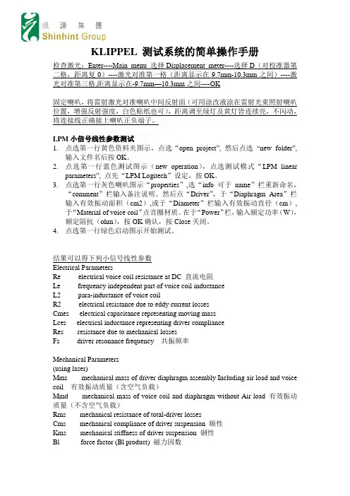
KLIPPEL 测试系统的简单操作手册检查激光:Enter----Main menu 选择Displacement meter----选择D(对校准器第二格,距离复0)----激光对准第一格(距离显示在9.7mm-10.3mm之间)----激光对准第三格,距离显示在-9.7mm—10.3mm之间----OK固定喇叭,将雷射激光对准喇叭中间反射面(可用涂改液涂在雷射光束照射喇叭位置,增强反射强度,白色贴纸也可),距离调至绿灯及黄灯皆连续亮,不闪动,将连接线正确接上喇叭正负端子。
LPM小信号线性参数测试1.点选第一行黄色资料夹图示,点选“open project”, 然后点选“new folder”,输入文件名后按OK。
2.点选第一行蓝色测试图示(new operation),点选测试模式“LPM linearparameters”, 点先“LPM Logitech”设定,按OK。
3.点选第一行灰色喇叭图示“properties”,选“info可于name”栏重新命名,“comment”栏输入备注说明。
然后点“Driver”,于“Diaphragm Area”栏输入有效振动面积(cm2),或于“Diameter”栏输入有效振动直径(cm),于“Material of voice coil”点音圈材质。
在于“Power”栏,输入额定功率(W),额定阻抗(ohm),按OK确认,按Close关闭。
4.点选第一行绿色启动图示开始测试。
结果可以得下列小信号线性参数Electrical ParametersRe electrical voice coil resistance at DC 直流电阻Le frequency independent part of voice coil inductanceL2 para-inductance of voice coilR2 electrical resistance due to eddy current lossesCmes electrical capacitance representing moving massLces electrical inductance representing driver complianceRes resistance due to mechanical lossesFs driver resonance frequency 共振频率Mechanical Parameters(using laser)Mms mechanical mass of driver diaphragm assembly Including air load and voice coil 有效振动质量(含空气负载)Mmd mechanical mass of voice coil and diaphragm without Air load 有效振动质量(不含空气负载)Rms mechanical resistance of total-driver lossesCms mechanical compliance of driver suspension 顺性Kms mechanical stiffness of driver suspension 钢性Bl force factor (Bl product) 磁力因数Lambdas suspension creep factorLoss factorsQtp total Q-factor considering all lossesQms mechanical Q-factor of driver in free air 机械阻尼因数Qes electrical Q-factor of driver in free air 电气阻尼系数Qts total Q-factor considering Re and Rms only 总阻尼系数Vas equivalent air volume of suspensionn0 reference efficiency (2 pi-radiation using Re)效率Lm sound pressure level 直流电阻活塞范围参考灵敏度Rmse Z root-mean-square fitting error of driver impedance Z(f)Rmse Hx root-mean-square fitting error of transfer function Hx(f)Series resistor resistance of series resistorSd diaphragm area 输入有效振动面积注:检查测试数据是否正确●点击“Table Linear Parameters” rmse Z 和rmse Hx 值都需小于4%●点击“Table Signal Characteristics” I SNR+D 值需大于20dB若喇叭失真明显高于杂讯,FO附近失真超过-20dB (10%),则将鼠标移至左上角视窗中代表本次测试的蓝色图示,击右键,点“Properties”,选Stimilus,于V oltage 栏将测试电压改小,再测一遍。

Newton ChannelMic Preamp, EQ, Compressor, SILKOperations Manual1.Read these instructions.2.Keep these instructions.3.Heed all warnings.4.Follow all instructions.5.Do not use this apparatus near water.6.Clean only with a dry cloth.7.Do not block any ventilation openings. Install in accordance with themanufacturer’s instructions.8.Do not install near any heat sources such as radiators, heat registers,stoves, or other apparatus (including amplifiers) that produce heat.9.Do not defeat the safety purpose of the polarized or grounding-typeplug. A polarized plug has two blades with one wider than the other.A grounding-type plug has two blades and a third grounding prong.The wide blade or the third prong are provided for your safety. If theprovided plug does not fit into your outlet, consult an electrician forreplacement of the obsolete outlet.10. Protect the power cord from being walked on or pinched particularly atplugs, convenience receptacles, and the point where they exit from theapparatus.11. Only use attachments/accessories specified by the manufacturer.12. Use only with a cart, stand, tripod, bracket, orthe apparatus. When a cart is used, use cautionavoid injury from tip-over.13. when unused for long periods of time.14. Refer all servicing to qualified service personnel. Servicing is requiredwhen the apparatus has been damaged in any way, such as power-supply cord or plug is damaged, liquid has been spilled or objects have fallen into the apparatus, the apparatus has been exposed to rain ormoisture, does not operate normally, or has been dropped.15. This apparatus shall not be exposed to dripping or splashing, and noobject filled with liquids, such as vases or beer glasses, shall be placed on the apparatus.16. Do not overload wall outlets and extension cords as this can result in a risk of fire or electric shock.17. This apparatus has been designed with Class-I construction and must be connected to a mains socket outlet with a protective earthingconnection (the third grounding prong).18. This apparatus has been equipped with a rocker-style AC mains power switch. This switch is located on the rear panel and should remainreadily accessible to the user.19. The MAINS plug or an appliance coupler is used as the disconnect device, so the disconnect device shall remain readily operable.20. N OTE: This equipment has been tested and found to comply with the limits for a Class B digital device, pursuant to part 15 of the FCC Rules. These limits are designed to provide reasonable protection against harmful interference in a residential installation. This equipment generates, uses, and can radiate radio frequency energy and, if not installed and used in accordance with the instructions, may cause harmful interference to radio communications. However, there is no guarantee that interference will not occur in a particular installation. If this equipment does cause harmful interference to radio or television reception, which can be determined by turning the equipment o and on, the user is encouraged to try to correct the interference by one or more of the following measures:•Reorient or relocate the receiving antenna.•Increase the separation between the equipment and the receiver.•Connect the equipment into an outlet on a circuit different from that to which the receiver is connected.•Consult the dealer or an experienced radio/TV technician for help.CAUTION: Changes or modifications to this device not expressly approved by Rupert Neve Designs LLC, could void the user's authority to operate the equipment under FCC rules.21. This apparatus does not exceed the Class A/Class B (whichever is applicable) limits for radio noise emissions from digital apparatus as set out in the radio interference regulations of the Canadian Department of Communications.ATTENTION — Le présent appareil numérique n’émet pas de bruits radioélectriques dépassant las limites applicables aux appareils numériques de class A/de class B (selon le cas) prescrites dans le réglement sur le brouillage radioélectrique édicté par les ministere des communications du Canada.22. Exposure to extremely high noise levels may cause permanent hearing loss. Individuals vary considerably in susceptibility to noise-induced hearing loss, but nearly everyone will lose some hearing if exposed tosufficiently intense noise for a period of time. The U.S. Government’s Occupational Safety and Health Administration (OSHA) has specifiedthe permissible noise level exposures shown in the following chart.According to OSHA, any exposure in excess of these permissible limitscould result in some hearing loss. To ensure against potentially dangerous exposure to high sound pressure levels, it is recommended that all persons exposed to equipment capable of producing highsound pressure levels use hearing protectors while the equipment is in operation. Ear plugs or protectors in the ear canals or over the ears must be worn when operating the equipment in order to preventpermanent hearing loss if exposure is in excess of the limits set forth here:Important Safety InstructionsWARNING — To reduce the risk of fire or electric shock, do notexpose this apparatus to rain or moisture.Duration, per day in hoursSound Level dBA, SlowResponse Typical Example 890Duo in small club 692495Subway Train3972100 Typical music via head phones 1.51021105Siren at 10 m distance 0.5 1100.25 or less 115Loudest parts at a rock concertThe lightning flash with arrowhead symbol within an equilateral triangle is intended to alert the user to the presence of uninsulated "dangerous voltage" within the product's enclosure, that may be of sufficient magnitude to constitute a risk of electric shock to persons.Le symbole éclair avec point de flèche à l'intérieur d'un triangle équilatéral est utilisé pour alerter l'utilisateur de la présence à l'intérieur du coffret de "voltage dangereux" non isolé d'ampleur suffisante pour constituer un risque d'éléctrocution.The exclamation point within an equilateral triangle is intended to alert the user of the presence of important operating and maintenance (servicing) instructions in the literature accompanying the appliance.Le point d'exclamation à l'intérieur d'un triangle équilatéral est employé pour alerter les utilisateurs de la présence d'instructions importantes pour le fonctionnement et l'entretien (service) dans le livret d'instruction accompagnant l'appareil.This symbol indicates that this product must not be disposed of with other waste. Instead, it is your responsibility to dispose of your waste equipment by handing it over to a designated collection point for the recycling of waste electrical andelectronic equipment. The separate collection and recycling of your waste equipment at the time of disposal will help conserve natural resources and ensure that it is recycled in a manner that protects human health and the environment. For moreinformation about where you can drop off your waste equipment for recycling, please contact your local city recycling office or the dealer from whom you purchased the product.Table of ContentsIntroductionBlock Diagram Newton Front Panel Newton Rear PanelNewton FeaturesSpecifications Limited Warranty 1 1 2 3 4 7 11N e w t o n C h a n n e l B l o c k D i a g r a mRupert Neve Designs Newton ChannelThank you for purchasing the Rupert Neve Designs Newton Channel. We hope you enjoy using this product as much as we have enjoyed designing and building it. The Newton Channel features Class-A analog signal paths, a 3-band discrete EQ section, a VCA compressor and custom Rupert Neve Designs transformer coupled outputs with variable SILK. The Newton Channel is designed to provide users with an intuitive, high-quality channel strip that is useful in a wide variety of recording and mixing applications.1N e w t o n C h a n n e l F r o n t P a n e l2N e w t o n C h a n n e l R e a r P a n e l3e v BNewton Channel Front Panel FeaturesMic Gain12-position rotary switch that controls the microphone preamp gain in 6dB steps. For line level input signals, set the Mic Gain to the “0dB” position.48VPush-button switch that illuminates RED when +48V Phantom Power is engaged.Ø (Polarity)Push-button switch that illuminates AMBER when engaged and inverts the phase of the preamp signal. TRIM31-detent potentiometer that allows the user to adjust the preamp gain within a range of +/- 6dB.HPFPush-button switch that illuminates GREEN when the variable high pass filter is engaged.FREQ31-detent potentiometer that allows the user to adjust the cutoff frequency of the variable high pass filter within a range of 20 Hz to 250 Hz.EQ INPush-button switch that illuminates GREEN when the EQ section is engaged.LF31-detent potentiometer that controls the amount of boost or cut for the low frequency shelf within a range of +/- 12dB.60/150Push-button switch that selects between the two available low frequency shelf frequencies: 60Hz (OUT) and 150Hz (IN).MID FREQ31-detent potentiometer that controls the frequency of the midband peaking EQ within a range of 220Hz to7kHz.MID31-detent potentiometer that controls the amount of boost or cut for the MID FREQ peaking EQ within a range of +/-12dB.8K/16KPush-button switch that selects between the two available high frequency shelf frequencies: 8kHz (OUT) and 16kHz (IN).4Newton Channel Front Panel Features (continued)HF31-detent potentiometer that controls the amount of boost or cut for the high frequency shelf within a range of +/-12dB.COMP INPush-button switch that illuminates GREEN when the compressor section is engaged.THRESHOLD31-detent potentiometer that controls the compressor threshold range from +20dBu to -30dBu. When the input signal rises above the set threshold level, compression begins with a soft-knee at a 2:1 ratio.RELEASE31-detent potentiometer that controls the compressor release time. The overall timing range available is 50mS (FAST) to 500mS (SLOW).GAIN31-detent potentiometer that controls the compressor make-up gain within a range of -6dB to +20dB.PRE EQPush-button switch that routes the compressor section ahead of the EQ section when engaged.SILKIlluminated push-button switch that toggles through the three available SILK modes: OFF, RED, and BLUE. RED enhances harmonic content in high mid and high frequencies. BLUE enhances harmonic content in low and low mid frequencies.TEXTURE31-detent potentiometer that controls the amount of SILK harmonics added within the transformer output stage when SILK is engaged.GR and OUT Metering8-segment LED meters that indicate compressor gain reduction (dB) and output level (dBu).POWERLED that illuminates GREEN when the Newton Channel is powered ON.5Newton Channel Rear Panel FeaturesPOWERIEC AC power inlet with integrated power switch. 100-240VAC at 50/60Hz. 35 Watts maximum AC power con-sumption.GROUND LIFTSlide switch that lifts XLR Pin 1 from chassis ground on the MAIN OUT and the -6dB OUT to help isolate from ground interference.-6dB OUTBalanced XLR output utilizing the center tap of a custom Rupert Neve Designs transformer.MAIN OUTBalanced XLR output utilizing a custom Rupert Neve Designs transformer.LINK1/4” TRS jack that allows two Newton Channel compressors to be linked together for stereo compressor operation. ONL Y INTENDED FOR USE WITH OTHER NEWTON CHANNEL LINK JACKS.INPUTBalanced XLR-1/4” TRS combo jack input that can be used for MIC or LINE level signals.6SpecificationsNote: All measurements typical, all measurements recorded using 25ft. XLR output cablesInput Impedance 8900 ohmsInput to Line Output (No Features Engaged, Un-weighted)Maximum Input Level +23.6 dBuNoise (Un-weighted)Line Out (Unity Gain) -102 dBu -6dB Line Out (Unity Gain) -107 dBu Line Out (+30dB Gain) -95 dBu Equivalent Input Noise @ +30dB Gain (EIN) -125 dBuMaximum Output Level @ 1kHz +23.6 dBuFrequency Response<10Hz to 30 kHz +/- 0.1 dB <5Hz to 70 kHz +/- 0.25 dB <5Hz to 140 kHz -3 dB THD+N BW (<10Hz to 22 kHz) 0 dBu at 1 kHz 0.0013 % +20 dBu at 1 kHz 0.0007 %Input to Line Output (Equalizer Engaged)Noise (BW <10 Hz to 22 kHz) -90 dBu THD+N @ 0 dBu (EQ Flat) 0.003% Input to Line Output (Compressor Engaged)Noise @ 0dB Make-Up Gain (BW <10 Hz to 22 kHz) -91 dBu THD+N @ 0 dBu (EQ Flat) 0.005% Compressor SectionAttack Time (fixed) 20mS Release Time (variable) 50mS (fast) to 500mS (slow) Product Dimensions (W x D x H) 19” (48.3 cm) x 8.125” (20.63 cm) x 1.75” (4.5 cm) Shipping Dimensions (W x D x H) 24” (61 cm) x 13” (33 cm) x 4” (10.2 cm) ShippingWeight 9 lbs. (4.1 kg)78M i c P r e a m p F r e q u e n c y R e s p o n s e G r a p h Z S O U R C E =150 o h m s , -45d B u I n p u t S i g n a l M e a s u r e m e n t s w e e p s t a k e n a t +6d B , +24d B , +42d B , a n d 60d B G A I N9E QF r e q u e n c y R e s p o n s eG r a p h10C o m p r e s s o r R a t i o S w e ep Z S O U R C E =150 o h m s , M e a s u r e m e n t s w e e p s t a k e n a t +10, 0, -10, -20, a n d -30d B u T h r e s h o l dPRODUCT WARRANTYRupert Neve Designs warrants this product to be free from defects in materials and workmanship for a period of three (3) years from date of purchase, and agrees to remedy any defect identified within such three year period by, at our option, repairing or replacing the product.LIMITATIONS AND EXCLUSIONSThis warranty, and any other express or implied warranty, does not apply to any product which has been improperly installed, subjected to usage for which the product was not designed, misused or abused, damaged during shipping, damaged by any dry cell battery, or which has been altered or modified in any way. This warranty is extended to the original end user purchaser only. A purchase receipt or other satisfactory proof of date of original purchase is required before any warranty service will be performed. THIS EXPRESS, LIMITED WARRANTY IS IN LIEU OF ALL OTHER WARRANTIES, EXPRESS OR IMPLIED, TO THE EXTEND ALLOWED UNDER APPLICABLE STATE LAW. I N NO EVENT SHALL RUPERT NEVE DESI GNS BE LI ABLE FOR ANY SPECI AL, I NCI DENTAL, OR CONSEQUENTIAL DAMAGES RESULTING FROM THE USE OF THIS PRODUCT. Some states do not allow the exclusion or limitation of consequential damages or limitations on how long an implied warranty lasts, so this exclusion may not apply to you.WARRANTY SERVICEIf you suspect a defect in this product, please contact our support staff for troubleshooting by phone (512-847-3013)oremail(**********************).Ifitisdeterminedthatthedeviceismalfunctioning,wewillissuea Return Material Authorization and provide instructions for shipping the device to our service department.Rupert Neve DesignsPO Box 1969Wimberley TX 78676tel: +1 512-847-3013fax: +1 512-847-8869775-00043 Rev A11。
QC 品质控制测试系统 - 线上终端测试C3版本:2.0特点效益• 在物理门限下非常快速地测量 • 高精度扫描技術• 简单门限计算,合格/不合格分类 • 自動檢測 Golden Unit – 标准参考件 • 自行開發的獨有Rub & Buzz 异音測試 (Meta Hearing 技术)• 自动重复生产线环境噪声检测 • T/S 參数 (Re, fs, Qts) • 阻抗, 频率响应 • 极性, 平均电平 • 闸性脈冲响应• 總諧波失真THD, 2nd – 5th 次失真,多音 • 驱动和悬边测试 • 線圈位置 - 毫米 • 悬边不平衡 – 百分比 % • 測試数據輸出工具 • 生產指数 (Cpk, Ppk) • 不同的操作级别(操作员、 品质控制工程师、程序员) • 高级編程版本 • 揚声器配对功具 • 自動檢測功放增益 • 測試報告产生器• 通过数字接口方便整合到生产装配线 • 中、英文操作手册特定的配置可能不包括上面列的所有特点提供100%的产品测试 确保产品的一致性比人耳听觉测试更加可靠 简易的直接的操作 生产线噪声免疫在生产进程中可以无缝整合 与Klippel R&D 分析仪系统兼容灵活可靠的解决方法满足不同 公司的需求高级编程语言提供不同编程要求应用扬声器 、耳机 、微声器 整個音頻系统 线上终端测试来料检查内容:总览 (2)硬件...............................................................................................................................................3 - 4 QC 軟件 (标準版本)....................................................................................................................5 - 7 操作模式.. (8)Rub & Buzz 异音....................................................................................错误!未定义书签。

Klippel操作指引Klippel 测试主要有三种测试模式:LPM测试(主要测参数,阻抗)LSI测试(主要测定位)SPL测试(主要测试SPL曲线及失真)。
以下就介绍这三种测试方法的详细操作指引。
一LPM测试1.测试之前先选好通道(一般情况,微型喇叭用SPEAKER 2,大喇叭用SPEAKER1)2.固定喇叭:将雷射激光对准喇叭中间反射面(可用涂改液涂在雷射光束照射喇叭位置,增强反射强度,白色贴纸也可),距离调至绿灯及黄灯皆连续亮,不闪动,将连接线正确接上喇叭正负端子。
3.参数设置1)建立档案,如图,选择第一行第一个图标,然后在弹出对话框选择New,然后输入档案名(一般为机种名)。
2)选择模块,在新建的档案中选择红框中的图标,然后在弹出的对话框中选择第三行LPM Linear parameters ,然后在右边的框内选择所需要的模块,例如:低频大喇叭选择倒数第三行的LPM Woofer T/S(Sp1)。
高音微型喇叭选择LPM Tweeter T/S(Sp2)3)设置参数,选择红框中图标,然后在在弹出的对话框中按照红框内内容输入。
4)点选绿箭头图标,就可以完成一个小信号测试。
二 LSI 测试LSI 测试一般是在测试LPM 的基础上再进行测试,喇叭的放置以及激光的调距都跟LPM 一样。
1.建立测试模块(以普通喇叭为例)选择左边第一行中LSI Woofer drive 右边选择(Default ).注意1:微型喇叭,请选择LSI Headphone Nonlin.P.Sp2 ,高音喇叭请选择 LSI Tweeter Driver 。
注意2:KLIPPEL 大信号测试最多支持500 ohm 阻抗 ,超过500 ohm 将无法测试大信号,如果正好是500 ohm ,请在大信号的参数设置里将阻抗改为499,才可以继续进行测试。
输入振动面积 输入阻抗 输入功率2.设置参数选择Protection ,然后按红框内输入,点选Im/Export,,然后按照红框内容输入参数输入最大功率输入BL输入振动质量输入阻抗3.设置完点选绿色箭头按钮就可以进行测试了。
SoundCheck电声测试仪Sequence编辑指导书(Speaker单体)前言:SoundCheck电声测试仪的Sequence编辑的总体步骤如下:Hardware(硬件设置)→Calibration(校准设置)→Stimulus(激励信号源设置)→Acquisition(接受数据过程)→Analysis (分析数据)→Post—Processing(处理获得的数据)→Limits(设置上下限)→Display(显示数据)一.新建一个Seq的名称如图1,打开SoundCheck软件,点击左上方工具栏“File”→“New”。
出现一个对话框,如图2,依次进入“SoundCheck 6.1”→“Sequences”→“Loudspeakers”目录,新建一个名字(可以随意建)。
输完以后按“OK”。
此时出现如图3的对话框,点击“Discard”。
图1图2图3点击“Discard”后,会出现一个seq编辑对话框——Sequence Editor(如图4)。
Seq的编辑就是在此对话框中完成。
图4二.Hardware在编辑框的左侧“Category”中选择对应的声卡类型,以CardDeluxe声卡为例,如图5点蓝后。
按“Insert”将声卡设置选项插至右侧“Sequence”框中,如图6。
图5 图6双击seq中的Hardware选项,会出现设置对话框,一般默认设置就可以了,点击OK即可,如图7。
图7三.Calibration在编辑框的左侧“Category”中选择对应的校准程序,将其点蓝,如图8。
按“Insert”将校准程序插至插至右侧“Sequence”框中,如图9。
图8图9双击校准程序,出现校准程序设置对话框。
首先校准功放,“Input”如图10设置,“Output”如图11设置,点击“Output”中的“Calibrate”即可对功放进行校准;其次校准人工耳,“Input”如图12设置,“Output”不用设置,点击“Input”中的“Calibrate”即可对人工耳进行校准。
SpeakerWorkShop简介SpeakerWorkShop是一款集测量,设计于一身的功能强大的自由软件。
包括扬声器单元的T/S参数,阻抗曲线,频响曲线,无源元件(电阻,电容)的测量;箱体,分频器网络的设计。
这里简单的介绍一下软件的基本情况。
软件的基本要求个人电脑一台;全双工声卡一块;软件平台支持WIN9X,WIN2000,WINXP辅助设备:测量用话筒;JIG;话筒放大器和功率放大器为推荐使用软件的用户界面SpeakerWorkShop典型的用户界面如下:图11. 红色框为软件的菜单部分,主要的基本选项,测量项目集中在这里。
2. 绿色框为软件创建的工程的资源部分,每个资源:单元,曲线,箱体,分频网络等资源由用户创建或导入并按照规定的目录结构排列以备调用。
3. 蓝色框为软件的工作区,调用的资源在这里被显示,并可以配合菜单完成测量项目。
软件的基本工作流程工程创建后,调用资源部分的资源显示在工作区并配合菜单部分完成一定的测量项目。
JIG这里介绍的JIG是自制的电阻箱,由国外的DIY爱好者设计,用于配合SpeakerWorkShop完成各测量项目。
本文对JIG 制作过程中的一些需要注意的地方简单说明一下。
图2SW1 为6A双排三档(上,中,下)开关SW2, SW3 为6A双排两档开关BP1-2, BP3-4 功放用接线柱J1 - J4 莲花座R1 8欧/20W 无感电阻R2, R3 1.175k/2W 5%R4 16欧 1/2W 1%R5 4欧1/2W 1%R6 543.2欧1/4W 5%R7 130.1欧1/4W5%D1 - D4 5.1V 1W Zener diode说明:R1为参考电阻R2, R3由于阻值特殊,可由4颗4.7k电阻并联获得R4(16欧),R5(4欧) 两颗电阻对精度要求严格,为1%R6, R7由于阻值特殊,可由两颗电阻并联获得。
作者使用680欧和2 .7k两颗电阻并联代替R6;使用180欧和470欧并联代替R7D1-D4 为过压保护,避免操作不当烧毁声卡LINE-IN口建议:由于此JIG对用到的电阻精度要求较高(尤其R4和R5),每个阻值的电阻可多买一些,在其中挑选阻值最接近的一颗使用以下是JIG的几种工作状态的简要说明,具体使用会在以后详细说明SW1 SW2 SW3 Mode DescriptionU L D IMPCAL16 BP3-BP4之间阻值为16欧,此模式用于参考电阻R1的校准D L D IMPCAL4 BP3-BP4之间阻值为4 欧,此模式用于参考电阻R1的校准C LD IMPMEAS 测量连接于BP3-BP4的设备的阻抗(包括扬声器单元的阻抗曲线)C RD DIRECT 此模式用于声道校准C R U FRMEAS-0DB 此模式用于频响曲线的测量,不对测量结果进行衰减U R U FRMEAS-10DB 此模式用于频响曲线的测量,对参考信号进行10DB衰减D R U FRMEAS-20DB 此模式用于频响曲线的测量,对参考信号进行20DB衰减图3基本原理与测前准备原理下文主要注重的是SpeakerWorkShop的基本工作原理,帮助初学者进一步了解测量过程。
用Klippel系统对扬声器频响近场测试的分析曾健【摘要】近年出现了一款室内条件下测试扬声器特性的Klippel系统,在普通房间里近场测试频响特性.借助一只普通的圆形扬声器,从理论基础和实际测试两个方面对扬声器进行分析对比,检验了该测试设备获得频响测试结果的可信性,并以此为基础,为选择扬声器的适用频段提供技术支持.【期刊名称】《电声技术》【年(卷),期】2017(041)011【总页数】4页(P15-18)【关键词】扬声器;近场测试;频响特性【作者】曾健【作者单位】四川湖山电器有限责任公司,四川绵阳621000【正文语种】中文【中图分类】TN643;O4241 圆形障板活塞运动时在轴向产生的声压假设有一个半径为a的圆形障板做活塞运动(见图1),障板上每个质点的振动速度设为uAejωt。
图1 做活塞运动的圆形障板根据声学理论[1],设圆形活塞上有一个内半径为ρ、外半径为ρ+dρ的环元,由于dρ极其微小,可以认为该环元上所有点到活塞中心轴(即柱坐标系的z轴)上的P(0,z)点的距离都是环元上的所有质点,辐射的声波到达P(0,z)点时,振幅相同、相位相同,叠加起来就是环元(环元面积为dS=2πρdρ)在半空间P(0,z)处产生的声压dP,即(1)所以由于2=ρ2+z2,所以2ρdρ=2d,这样p=jkρ0c0uAejωte-jkd即(2)式中,式(2)中因子决定了轴向P(0,z)点的声压变化规律。
当时,P(0,z)点处的声压为零。
当时,P(0,z)点处声压幅值极大。
观察点P(0,z)在轴向位置发生微小变化,即z值略微变化时,乘上后,可以使得正弦函数的幅角改变很多,所以极大值与极小值的分布很密集。
随着距离的增加,极大与极小的位置间隔变大。
图2显示了因子随着归一化轴向距离的变化情况。
图中进行数值计算的时候,活塞的半径设为10 cm(后同)。
图2 声压正弦因子随归一化轴向距离的变化在圆形活塞的中轴上,距离很近的时候,随着频率的增加,声压随距离的微小变化而显著改变。
Klippel操作指引
Klippel 测试主要有三种测试模式:LPM测试(主要测参数,阻抗)LSI测试(主要测定位)SPL测试(主要测试SPL曲线及失真)。
以下就介绍这三种测试方法的详细操作指引。
一LPM测试
1.测试之前先选好通道(一般情况,微型喇叭用SPEAKER 2,大喇叭用SPEAKER1)
2.固定喇叭:将雷射激光对准喇叭中间反射面(可用涂改液涂在雷射光束照射喇叭位置,增强反射强度,白色贴纸也可),距离调至绿灯及黄灯皆连续亮,不闪动,将连接线正确接上喇叭正负端子。
3.参数设置
1)建立档案,如图,选择第一行第一个图标,然后在弹出对话框选择New,然后输入档案名(一般为机种名)。
2)选择模块,在新建的档案中选择红框中的图标,然后在弹出的对话框中选择第三行LPM Linear parameters ,然后在右边的框内选择所需要的模块,例如:低频大喇叭选择倒数第三行的LPM Woofer T/S(Sp1)。
高音微型喇叭选择LPM Tweeter T/S(Sp2)
3)设置参数,选择红框中图标,然后在在弹出的对话框中按照红框内内容输入。
4)点选绿箭头图标,就可以完成一个小信号测试。
二 LSI 测试
LSI 测试一般是在测试LPM 的基础上再进行测试,喇叭的放置以及激光的调距都跟LPM 一样。
1.建立测试模块(以普通喇叭为例)选择左边第一行中LSI Woofer drive 右边选择(Default ).
注意1:微型喇叭,请选择LSI Headphone Nonlin.P.Sp2 ,高音喇叭请选择 LSI Tweeter Driver 。
注意2:KLIPPEL 大信号测试最多支持500 ohm 阻抗 ,超过500 ohm 将无法测试大信号,如果正好是500 ohm ,请在大信号的参数设置里将阻抗改为499,才可以继续进行测试。
输入振动面积 输入阻抗 输入功率
2.设置参数
选择Protection ,然后按红框内输入,点选Im/Export,,然后按照红框内容输入参数
输入最大功率
输入BL
输入振动质量
输入阻抗
3.设置完点选绿色箭头按钮就可以进行测试了。
三SPL测试
1.放置喇叭与麦克风
选择合适的测试板将喇叭放置在障板上,调节麦克风距离,如无特殊要求,测试条件为1M1W.
2.建立模块,选择TRF Transfer function 中的TRF SPL+ harmonics
3. 设置参数 分别在第一栏选择选择Stimulus Input Display 按照如下所示,输入参数
4.点选绿色箭头图标,进行测试。
输入起始频率
选择1 选择Off
选择IN 2
分别输入0.05,94
一般输入3,可更高
选择Speaker 1。