本特利3300监测系统说明书
- 格式:pdf
- 大小:653.18 KB
- 文档页数:27
Specifications and Ordering InformationPart Number 141194-01Rev. T (12/12)Bently Nevada* Asset Condition Monitoring 3300 XL 8mm Proximity Transducer SystemDescription The 3300 XL 8 mm Proximity Transducer System consists of: ∙ One 3300 XL 8 mm probe,∙ One 3300 XL extension cable 1, and ∙ One 3300 XL Proximitor * Sensor 2. The system provides an output voltage that is directly proportional to thedistance between the probe tip and the observed conductive surface and can measure both static (position) and dynamic (vibration) values. The system’s primary applications are vibration and position measurements on fluid-film bearing machines, as well as Keyphasor * reference and speed measurements 3.The 3300 XL 8 mm system delivers the most advanced performance in our eddy current proximity transducer systems. The standard 3300 XL 8 mm 5-metre system also fully complies with the American Petroleum Institute’s (API) 670 Standard (4th Edition) for mechanical configuration, linear range, accuracy, and temperature stability. All 3300 XL 8 mm proximity transducer systems provide this level of performance and support complete interchangeability of probes, extension cables, and Proximitor sensors, eliminating the need to match or bench calibrate individual componentsEach 3300 XL 8 mm Transducer System component is backward-compatible and interchangeable 4 with other non-XL 3300 series 5 mm and 8 mm transducer system components 5. This compatibility includes the 3300 5 mm probe, for applications in which an 8 mm probe is too large for the available mounting space 6,7.Proximitor SensorThe 3300 XL Proximitor Sensor incorporates numerous improvements overprevious designs. Its physical packaging allows you to use it in high-density DIN-rail installations. You can also mount the sensor in a traditional panel mount configuration, where it shares an identical 4-hole mounting “footprint” with older Proximitor Sensor designs. The mounting base for either option provideselectrical isolation and eliminates the need for separate isolator plates. The 3300 XL Proximitor Sensor is highly immune to radio frequency interference, allowing you to install it in fiberglass housings without adverse effects from nearby radio frequency signals. The 3300 XL Proximitor Sensor’s improved RFI/EMI immunity satisfies European CE mark approvals without requiring special shielded conduit or metallic housings, resulting in lower installation costs and complexity. The 3300 XL’s SpringLoc terminal strips require no special installation tools and facilitate faster, more robust field wiring connections by eliminating screw-type clamping mechanisms that can loosen.Proximity Probe and Extension CableThe 3300 XL probe and extension cable also reflect improvements over previous designs. A patented TipLoc* molding method provides a more robust bond between the probe tip and the probe body. The probe’s cable incorporates a patented CableLoc* design that provides 330 N (75 lbf) pull strength to more securely attach the probe cable and probe tip. You can also order 3300 XL 8 mm probes and extension cables with an optional FluidLoc* cable option. This option prevents oil and other liquids from leaking out of the machine through the cable’s interior.ConnectorsThe 3300 XL probe, extension cable, and Proximitor sensor have corrosion-resistant, gold-plated ClickLoc* connectors. These connectors require only finger-tight torque (the connectors will "click" when tight), and the specially-engineered locking mechanism prevents the connectors from loosening. These connectors require no special tools for installation or removal.You can order the 3300 XL 8 mm probes and extension cables with connector protectors already installed. We can also supply connector protectors separately for field installations (such as when an application must run the cable through restrictive conduit). We recommend connector protectors for all installations to provide increased environmental protection8.Extended Temperature Range ApplicationsAn extended temperature range (ETR) probe and ETR extension cable are available for applications in which either the probe lead or extension cable may exceed the standard 177 ︒C (350 ︒F) temperature specification. The ETR probe has an extended temperature rating for up to 218 ︒C (425 ︒F). The ETR extension cable rating is up to 260 ︒C (500 ︒F). Both the ETR probe and cable are compatible with standard temperature probes and cables, for example, you can utilize an ETR probe with the 330130 extension cable. The ETR system uses the standard 3300 XL Proximitor Sensor. Note that when you use any ETR component as part of your system, the ETR component limits the system accuracy to the accuracy of the ETR system. Description Notes:1.1-metre systems do not use an extension cable.2.Proximitor sensors are supplied by default from thefactory calibrated to AISI 4140 steel. Calibration toother target materials is available upon request.3.Consult Bently Nevada* Applications Note,Considerations when using Eddy Current ProximityProbes for Overspeed Protection Applications, whenconsidering this transducer system for tachometer or overspeed measurements.4.3300 XL 8 mm components are both electrically andphysically interchangeable with non-XL 3300 5 mmand 8 mm components. Although the packaging ofthe 3300 XL Proximitor Sensor differs from itspredecessor, its design fits in the same 4-holemounting pattern when used with the 4-holemounting base, and will fit within the same mounting space specifications (when minimum permissiblecable bend radius is observed).5.Mixing XL and non-XL 3300-series 5 mm and 8 mmsystem components limits system performance to the specifications for the non-XL 3300 5 mm and 8 mmTransducer System.6.The 3300-series 5 mm probe (refer to Specificationsand Ordering Information p/n 141605-01) usessmaller physical packaging, but does not reduce theside view clearances or tip-to-tip spacingrequirements as compared to an 8 mm probe. It isused when physical (not electrical) constraintspreclude the use of an 8 mm probe. When yourapplication requires narrow side view probes, use the 3300 NSv* Proximity Transducer System (refer toSpecifications and Ordering Information p/n 147385-01).7.8 mm probes provide a thicker encapsulation of theprobe coil in the molded PPS plastic probe tip. Thisresults in a more rugged probe. The larger diameterof the probe body also provides a stronger, morerobust case. We recommend that you use 8 mmprobes when possible to provide optimal robustnessagainst physical abuse.8.Each 3300 XL extension cable includes silicone tapethat you can use instead of connector protectors. We do not recommend silicone tape for applications that will expose the probe-to-extension cable connectionto turbine oil.Specifications and Ordering InformationSpecificationsUnless otherwise noted, the following specifications are for a 3300 XL 8 mm Proximitor Sensor, extension cable and 8 mm probe between +18 ︒C and +27 ︒C (+64 ︒F to +80 ︒F), with a -24 Vdc power supply, a 10 kΩ load, an AISI 4140 steel target, and a probe gapped at 1.27 mm (50 mils). Performance characteristics apply to systems that consist solely of 3300 XL 8 mm components. The system accuracy and interchangeability specifications do not apply to transducer systems that are calibrated to any target other than our AISI 4140 steel target.ElectricalProximitorSensor InputAccepts one non-contacting3300-series 5 mm, 3300 8 mm or3300 XL 8 mm Proximity Probeand Extension Cable.PowerRequires -17.5 Vdc to -26 Vdcwithout barriers at 12 mAmaximum consumption, -23 Vdcto -26 Vdc with barriers.Operation at a more positivevoltage than -23.5 Vdc can resultin reduced linear range.SupplySensitivityLess than 2 mV change in outputvoltage per volt change in inputvoltage.OutputResistance50 ΩNominal ProbeDC ResistanceResistance (R PROBE) from CenterConductor to Outer ConductorProbe Length R PROBE (Ω)0.5 7.45± 0.501.0 7.59 ± 0.501.5 7.73± 0.502.0 7.88 ± 0.503.0 8.17 ± 0.605.0 8.73± 0.709.0 9.87 ± 0.90 NominalExtension CableDC ResistanceResistance (R CORE) from CenterConductor to Center ConductorLength of ExtensionCable (m)R CORE (Ω)3.0 0.66± 0.103.5 0.77 ± 0.124.0 0.88± 0.134.5 0.99 ± 0.156.0 1.32± 0.217.0 1.54± 0.237.5 1.65 ± 0.258.0 1.76± 0.268.5 1.87 ± 0.28Resistance (R JACKET) from OuterConductor to Outer ConductorLength of ExtensionCable (m)R JACKET (Ω)3.0 0.20± 0.043.5 0.23 ± 0.054.0 0.26± 0.054.5 0.30 ± 0.066.0 0.39± 0.087.0 0.46± 0.097.5 0.49 ± 0.108.0 0.53± 0.118.5 0.56 ± 0.11Specifications and Ordering InformationExtension CableCapacitance69.9 pF/m (21.3 pF/ft) typical Field Wiring0.2 to 1.5 mm2(16 to 24 AWG) .Recommend using 3-conductorshielded triad cable and tinnedfield wiring. Maximum length of305 metres (1,000 feet) betweenthe 3300 XL Proximitor Sensorand the monitor. See thefrequency response graphs inthrough Figure 13 (pages 28 and29) for signal rolloff at highfrequencies when using longerfield wiring lengths.Linear Range2 mm (80 mils). Linear rangebegins at approximately 0.25 mm(10 mils) from target and is from0.25 to 2.3 mm (10 to 90 mils)(approximately –1 to –17 Vdc). RecommendedGap Setting forRadial Vibration-9Vdc [approximately 1.27 mm(50 mils)]IncrementalScale Factor(ISF)Standard 5-or 1- metreSystem:7.87 V/mm (200 mV/mil) ± 5%including interchangeability errorwhen measured in increments of0.25 mm (10 mils) over the 80 millinear range from 0 °C to +45 °C(+32 °F to +113 °F).Standard9-metreSystem:7.87 V/mm (200 mV/mil) ± 6.5%including interchangeability errorwhen measured in increments of0.25 mm (10 mils) over the 80 millinear range from 0 °C to +45 °C(+32 °F to +113 °F).ExtendedTemperatureRange (ETR)for 5- and9-MetreSystems:7.87 V/mm (200 mV/mil) ± 6.5%including interchangeability errorwhen measured in increments of0.25 mm (10 mils) over the 80 millinear range from 0 °C to +45 °C(+32 °F to +113 °F).Deviation from best fit straight line (DSL)Standard 5-or 1-metreSystem:Less than ±0.025 mm (±1 mil) withcomponents at 0 °C to +45 °C(+32 °F to +113 °F).Standard9-metreSystem:Less than ±0.038 mm (±1.5 mil)with components at 0 °C to +45°C (+32 °F to +113 °F).ExtendedTemperatureRange 5 and9-metreSystems:Less than ±0.038 mm (±1.5 mil)with components at 0 °C to +45°C (+32 °F to +113 °F). PerformanceOver ExtendedTemperaturesStandard 5-or 1-metreSystem:Over a probe temperature rangeof –35 °C to +120 °C (-31 °F to+248 °F) with the Proximitorsensor and extension cablebetween 0 °C to +45°C (+32 °F to+113 °F), the ISF remains within±10% of 7.87 V/mm (200 mV/mil)and the DSL remains within±0.076 mm (±3 mils).Specifications and Ordering InformationOver a Proximitor sensor andextension cable temperaturerange of –35 °C to +65 °C (-31 °Fto +149 °F) with the probebetween 0 °C to +45 °C (+32 °F to+113 °F), the ISF remains within±10% of 7.87 V/mm (200 mV/mil)and the DSL remains within±0.076 mm (±3 mils).Standard9-metreSystem:Over a probe temperature rangeof –35 °C to +120 °C (-31 °F to+248 °F) with the Proximitorsensor and extension cablebetween 0 °C to +45°C (+32 °F to+113 °F), the ISF remains within±18% of 7.87 V/mm (200 mV/mil)and the DSL remains within±0.152 mm (±6 mils).Over a Proximitor sensor andextension cable temperaturerange of –35 °C to +65 °C (-31 °Fto +149 °F) with the probebetween 0 °C to +45 °C (+32 °F to+113 °F), the ISF remains within±18% of 7.87 V/mm (200 mV/mil)and the DSL remains within±0.152 mm (±6 mils).ExtendedTemperatureRange 5 and9-metreSystems:Over a probe and extension cabletemperature range of –35 °C to+260 °C (-31 °F to +500 °F) withthe Proximitor sensor between 0°C to +45 °C (+32 °F to +113 °F),the ISF remains within ±18% of7.87 V/mm (200 mV/mil) and theDSL remains within ±0.152 mm(±6 mils).FrequencyResponse(0 to 10 kHz), +0, -3 dB, with up to305 metres (1000 feet) of fieldwiring. MinimumTarget Size15.2 mm (0.6 in) diameter (flattarget)Shaft DiameterMinimum:50.8 mm (2 in)RecommendedMinimum:76.2 mm (3 in)When gapped at the center of thelinear range, the interactionbetween two separate transducersystems (cross-talk) will be lessthan 50 mV on shaft diameters ofat least 50 mm (2 in) or greater.You should take care to maintainminimum separation oftransducer tips, generally at least40 mm (1.6 in) for axial positionmeasurements or 38 mm (1.5 in)for radial vibration measurementsto limit cross-talk to 50 mV or less.Radial vibration or positionmeasurements on shaftdiameters smaller than 76.2 mm(3 in) will generally change thescale factor.Effects of 60 HzMagnetic Fieldsup to 300 GaussOutput Voltage in Mil pp/Gauss Gap(mil)5- or1-metreProximitorSensor9-metreProximitorSensorProbeExt.Cable10 0.0119 0.0247 0.0004 0.000450 0.0131 0.0323 0.0014 0.001490 0.0133 0.0348 0.0045 0.0045Specifications and Ordering InformationSpecifications and Ordering InformationCompliance and CertificationsEMCEuropean Community Directives: EMC Directive 2004/108/EC Standards:EN61000-6-2 EN61000-6-4MaritimeABS 2009 Steel Vessels Rules 1-1-4/7.7, 4-8-3/1.11.1, 4-9-7/13Hazardous Area ApprovalsNote: Multiple approvals for hazardous areas certified byCanadian Standards Association (C/US) in North America and by Baseefa for Europe and IEC Ex.Field Wiring Limitations:Type Approval: Gas GroupCapacitance(µF)Inductance (mH)L/R Ratio (μH/Ω)ATEX and IEC Zone 0/1IIC 0.078 0.99 29.2IIB 0.645 7.41 117.0IIA 2.144 15.6 234.0 CSA Div 1A &B 0.070 1.0 29.2C 0.600 5.0 117.0D 2.09 11.0 234.0CSA Div 2 All 0.460 100.0 N/A North America3300 XL Proximitor Sensor and probe, ia:Ex ia IIC T4/T5; Class I Zone 0 or Class 1; Groups A, B, C, and D, Class II, Groups E, F and G, Class III when installed with intrinsically safe zener barriers per drawing 141092 or when installed with galvanic isolators.3300 XL Proximitor Sensor and probe, nA:Ex nA IIC T4/T5 Class I Zone 2 or Class I, Division 2, Groups A, B, C, and D, when installed without barriers per drawing 140979. T 5 @ T a = -35 ︒C to +85 ︒C. T4 @ Ta= -51 ︒C to +100 ︒C.Europe3300 XL Proximitor Sensor, ia :II 1 G EEx ia IIC T4/T5 when installed per drawing 141092.3300 XL Proximitor Sensor, nA:II 3 G Ex nA II T4/T5 when installed per drawing 140979. T5 @ Ta= -35 ︒C to +85 ︒C T4 @ Ta= -51 ︒C to +100 ︒C3300 XL 8mm probe, ia: II 1 G EEx ia IIC, Temperature Classification per Table 1 when installed per drawing 142491. 3300 XL 8mm probe, nA:II 3 G EEx nA II, Temperature Classification per Table 1 when installed per drawing 142491.Brazil3300 XLProximitorSensor, ia:BR-Ex ia IIC T4(-51°C ≤ Ta ≤ +100°C)BR-Ex ia IIC T5(-35°C ≤ Ta ≤ +85°C)Terminal J1Terminal J2Ui= -28V Ii= 140mA Pi= 0.91W Ci = 0 FLi =0 H Uα= -28V Iα= 140mA Pα= 0.91W Ci = 0 FLi =0 .7 mHApplicable for Part numbers:330180, 330980, 330780, 330850,330878.3300 XL8mm and3300 5mmEddy CurrentProbes, ia:BR-Ex ia IIC TemperatureClassification per Table 1.Ui = -28V Ci = 0 FIi = 140 mA Li = 0 HPi = 0.91 WIEC Ex3300 XLProximitorSensor, ia:Ex ia IIC T4 (-51°C ≤ Ta ≤ +100°C) /T5 (-35ºC ≤ Ta ≤ +85ºC)Ui= -28V Ci = 0Ii= 140mA Li =10µHPi= 0.84W3300 XLProximitorSensor, nA:Ex nA II T4 (-51°C ≤ Ta ≤ +100°C) /T5 (-35°C ≤ Ta ≤ +85°C)Ui = -28V3300 XL8mm and3300 5mmEddy CurrentProbes, ia:Ex ia IIC TemperatureClassification per Table 1.Ui = -28V Ci = 1.5 nFIi = 140 mA Li = 200 µHPi = 0.84 W3300 XL8mm and3300 5mmEddy CurrentProbes, nA:Ex nA II for Zone 2 TemperatureClassification per Table 1.Table 1: Probe Temperature ClassificationTemperatureClassificationAmbient Temperature(Probe Only)T1 -51ºC to +232ºCT2 -51ºC to +177ºCT3 -51ºC to +120ºCT4 -51ºC to +80ºCT5 -51ºC to +40ºCHazardous AreaConditions ofSafe Use:ATEX:Follow the conditions of safe useincluded on the Declaration ofConformance sent with eachproduct.CanadianStandardsAssociation(CSA):Division 1 (Intrinsically safe):Install per Bently Nevada drawing141092.Division 2 (non-Incendive): Installper Bently Nevada drawing140979.Specifications and Ordering InformationIECEx:Zone 0 (Intrinsically safe): TheProximitor Sensor must beinstalled to minimize the risk ofimpact or friction with othermetallic surfaces.Zone 2 (non-Incendive): Theprobe must be supplied from avoltage-limited source. MechanicalProbe TipMaterialPolyphenylene sulfide (PPS). Probe CaseMaterialAISI 303 or 304 stainless steel(SST).Probe CableSpecificationsStandardcable:75Ω triaxial, fluoroethylenepropylene (FEP) insulated probecable in the following total probelengths: 0.5, 1, 1.5, 2, 3, 5, or 9metres.ExtendedTemperatureRange cable:75Ω triaxial, perfluoroalkoxy (PFA)insulated probe cable in thefollowing total probe lengths: 0.5,1, 1.5, 2, 5, or 9 metres.Armor(optional onboth):Flexible AISI 302 or 304 SST withFEP outer jacket.Tensile Strength(MaximumRated):330 N (75 lbf) probe case to probelead.270 N (60 lbf) at probe lead toextension cable connectors.ConnectorMaterial:Gold-plated brass or gold-platedberyllium copper.Probe CaseTorque:Probe TypeMaximumRatedRecommended Standardforward-mountedprobes33.9 N∙m(300 in∙lbf)11.2 N∙m(100 in∙lbf) Standard forward-mount probes -first three threads22.6 N∙m(200 in∙lbf)7.5 N∙m(66 in∙lbf)Reverse-mountprobes22.6 N∙m(200 in∙lbf)7.5 N∙m(66 in∙lbf)Extension CableMaterialStandardcable:75Ω triaxial, fluoroethylenepropylene (FEP) insulated.ExtendedTemperatureRange cable:75Ω triaxial, perfluoroalkoxy (PFA)insulated.MinimumCable BendRadius:25.4 mm (1.0 in)Note: 3300 XL 8 mm components are both electrically and physically interchangeable with non-XL 3300 5 mm and 8mm components when minimum permissible cable bendradius is observed..Specifications and Ordering InformationConnectorMaterial:Gold-plated brass or gold-platedberyllium copper.MaximumConnectorTorque:0.565 N∙m (5 in∙lbf) Connector-to-connectorrecommendedtorque:Connector Type Tightening Instructions Two 3300 XL gold"click" typeconnectorsFinger tightOne non-XL stainlesssteel connector and one 3300 XLconnector Finger tight plus 1/8 turnusing pliersProximitorSensor MaterialA308 aluminumConnectorMaterial:Gold-plated brass or gold-platedberyllium copper.System Length5 or 9 metres (including extensioncable) or 1 metre (probe only). Total SystemMass (Typical)0.7 kg (1.5 lbm)Probe:323 g (11.4 oz)ExtensionCable:34 g/m (0.4 oz/ft)ArmoredExtensionCable:103 g/m (1.5 oz/ft)ProximitorSensor:246 g (8.67 oz) Environmental LimitsProbe Temperature RangeOperating andStorageTemperatureStandardProbe:-51 °C to +177 °C (-60 °F to +350°F)ExtendedTemperatureRange Probe:-51 °C to +218 °C (-60 °F to+425°F) for the probe tip; -51 °C to+260 °C (-60 °F to +500 °F) for theprobe cable and connector. Note: Exposing the probe to temperatures below –34 ︒C (-30 ︒F) may cause premature failure of the pressure seal. Probe Pressure3300 XL 8 mm probes aredesigned to seal differentialpressure between the probe tipand case. The probe sealingmaterial consists of a Viton®O-ring. Probes are not pressuretested prior to shipment. Contactour custom design department ifyou require a test of the pressureseal for your application.Note: It is the responsibility of the customer or user to ensure that all liquids and gases are contained and safelycontrolled should leakage occur from a proximity probe.In addition, solutions with high or low pH values mayerode the tip assembly of the probe causing medialeakage into surrounding areas. Bently Nevada, Inc. willnot be held responsible for any damages resulting fromleaking 3300 XL 8 mm proximity probes. In addition, 3300XL 8 mm proximity probes will not be replaced under theservice plan due to probe leakage.Specifications and Ordering InformationExtension Cable Temperature Range Operating andStorageTemperatureStandardCable:-51 °C to +177 °C (-60 °F to +350°F)ExtendedTemperatureRange Cable:-51 °C to +260 °C (-60 °F to +500°F)Proximitor Sensor Temperature Range OperatingTemperature-51 °C to +100 °C (-60 °F to +212°F)StorageTemperature-51 °C to +105 °C (-60 °F to +221°F)RelativeHumidityLess than a 3% change inAverage Scale Factor (ASF) whentested in 93% humidity inaccordance with IEC standard68-2-3 for up to 56 days. PatentsComponents or proceduresdescribed in one or more of thefollowing patents apply to thisproduct: 5,016,343; 5,126,664;5,351,588; and 5,685,884.Specifications and Ordering InformationOrdering Information Probes3300 XL 8 mm Proximity Probes:330101 3300 XL 8 mm Probe, 3/8-24 UNF thread, without armor2330102 3300 XL 8 mm Probe, 3/8-24 UNF thread, with armor2Part Number-AXX-BXX-CXX-DXX-EXXA:Unthreaded Length OptionNote: Unthreaded length must be at least 0.8 inches less than the case length.Order in increments of 0.1 inLength configurations:Maximum unthreaded length: 8.8 inMinimum unthreaded length: 0.0 inExample:0 4 = 0.4 inB:Overall Case Length OptionOrder in increments of 0.1 inThreaded length configurations:Maximum case length: 9.6 inMinimum case length: 0.8 inExample:2 4 = 2.4 inC:Total Length Option0 50.5 metre (1.6 feet)1 0 1.0 metre (3.3 feet)1 5 1.5 metre (4.9 feet)2 0 2.0 metres (6.6 feet)3 0 3.0 metres (9.8 feet)5 0 5.0 metres (16.4 feet)9 09.0 metres (29.5 feet)Notes: 3-metre length option is only available on 330101 probes, and are designed for use with the 9-metre Proximitorsensor only.5-metre probes are designed for use with the 5-metreProximitor sensor only.D:Connector and Cable-Type Option0 1Miniature coaxial ClickLocconnector with connectorprotector, standard cable0 2 Miniature coaxial ClickLocconnector, standard cable1 1Miniature coaxial ClickLocconnector with connectorprotector, FluidLoc cable1 2Miniature coaxial ClickLocconnector, FluidLoc cable E:Agency Approval Option0 0 Notrequired0 5 MultipleApprovals 3300 XL 8 mm Proximity Probes, Metric: 330103 3300 XL 8 mm Probe, M10 x 1 thread, without armor2330104 3300 XL 8 mm Probe, M10 x 1 thread, with armor2Part Number-AXX-BXX-CXX-DXX-EXXA:Unthreaded Length OptionNote: Unthreaded length must be at least 20 mm less than the case length.Order in increments of 10 mm.Length configuration:Maximum unthreaded length: 230mmMinimum unthreaded length: 0 mmExample:0 6 = 60 mmB:Overall Case Length OptionOrder in increments of 10 mm.Metric thread configurations:Maximum length: 250 mmMinimum length: 20 mmExample:0 6 = 60 mmC:Total Length Option0 50.5 metre (1.6 feet)1 0 1.0 metre (3.3 feet)1 5 1.5 metres (4.9 feet)2 0 2.0 metres (6.6 feet)5 0 5.0 metres (16.4 feet)Note: 5-metre probes are designed for use with the 5-metre Proximitor sensor only.9 09.0 metres (29.5 feet)D: Connector and Cable-Type Option0 1 Miniature coaxial ClickLocconnector with connectorprotector, standard cable0 2 MiniaturecoaxialClickLocconnector, standard cable1 1 MiniaturecoaxialClickLocconnector with connectorprotector, FluidLoc cable1 2 MiniaturecoaxialClickLocconnector, FluidLoc cable E:Agency Approval Option0 0 Not required0 5 MultipleApprovalsSpecifications and Ordering Information3300 XL 8 mm Reverse Mount Probes330105-02-12-CXX-DXX-EXX, 3/8-24 UNF threads2 330106-05-30-CXX-DXX-EXX, M10 x 1 threads2Option DescriptionsC:Total Length Option0 50.5 metre (1.6 feet)1 0 1.0 metre (3.3 feet)1 5 1.5 metre (4.9 feet)2 0 2.0 metres (6.6 feet)5 0 5.0 metres (16.4 feet)Note: 5-metre probes are designed for use with the 5-metre Proximitor sensor only.9 09.0 metres (29.5 feet)D: Connector Option0 2 MiniatureClickLoccoaxialconnector1 2 MiniatureClickLoccoaxialconnector, FluidLoc cable Note: The FluidLoc cable option –12 is not necessary on the vast majority of 330105 and 330106 installations due to thepresence of the probe sleeve. Consider carefully theapplication before ordering the FluidLoc cable option forthese probes.E:Agency Approval Option0 0 Notrequired0 5 MultipleApprovals 3300 XL 8 mm Proximity Probes, Smooth Case: 330140 3300 XL 8 mm Probe without armor1330141 3300 XL 8 mm Probe with armor1Part Number-AXX-BXX-CXX-DXXOption DescriptionsA:Overall Case Length OptionOrder in increments of 0.1 inLength configurations:Maximum length: 9.6 inMinimum length: 0.8 inExample:2 4 = 2.4 inB:Total Length Option0 50.5 metre (1.6 feet)1 0 1.0 metre (3.3 feet)1 5 1.5 metres (4.9 feet)2 0 2.0 metres (6.6 feet)5 0 5.0 metres (16.4 feet)Note: 5-metre probes are designed for use with the 5-metre Proximitor sensor only.9 09.0 metres (29.5 feet) C:Connector and Cable-Type Option0 1 MiniaturecoaxialClickLocconnector with connectorprotector, standard cable0 2 MiniaturecoaxialClickLocconnector, standard cable1 1 MiniaturecoaxialClickLocconnector with connectorprotector, FluidLoc cable1 2 MiniaturecoaxialClickLocconnector, FluidLoc cable D:Agency Approval Option0 0 Not required0 5 MultipleApprovals 3300 XL 8 mm Extended Temperature Range (ETR) Proximity Probes:330191 3300 XL 8 mm ETR Probe, 3/8-24 UNF thread, without armor330192 3300 XL 8 mm ETR Probe, 3/8-24 UNF thread, with armorPart Number-AXX-BXX-CXX-DXXA:Unthreaded Length OptionNote: Unthreaded length must be at least 0.8 inches less than the case length.Order in increments of 0.1 inLength configurations:Maximum unthreaded length: 8.8 inMinimum unthreaded length: 0.0 inExample:1 5 = 1.5 inB:Overall Case Length OptionOrder in increments of 0.5 inThreaded length configurations:Maximum case length: 9.6 inMinimum case length: 0.8 inExample:2 5 = 2.5 inC:Total Length Option0 50.5 metre (1.6 feet)1 0 1.0 metre (3.3 feet)1 5 1.5 metre (4.9 feet)2 0 2.0 metres (6.6 feet)5 0 5.0 metres (16.4 feet)Note: 5-metre probes are designed for use with the 5-metre Proximitor sensor only.9 09.0 metres (29.5 feet)D:Agency Approval Option0 0 Notrequired0 5 MultipleApprovalsSpecifications and Ordering Information。
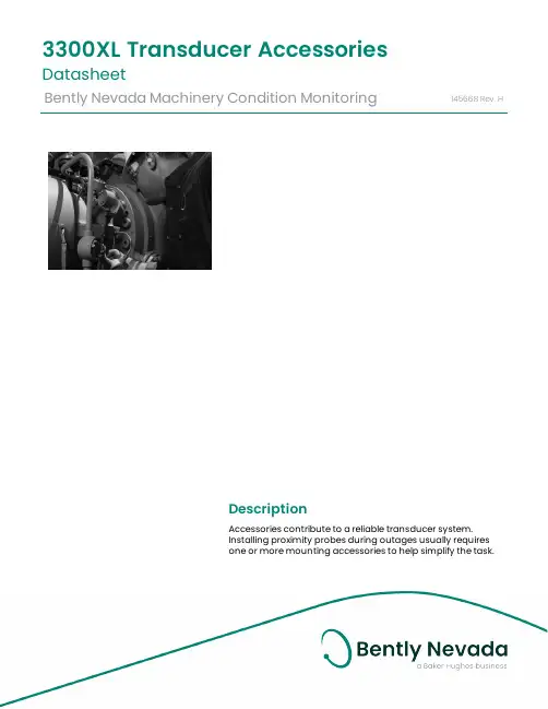
DescriptionAccessories contribute to a reliable transducer system. Installing proximity probes during outages usually requiresone or more mounting accessories to help simplify the task.3300XL Transducer AccessoriesDatasheetBently Nevada Machinery Condition Monitoring145668Rev.HThese accessories allow you to quickly and efficiently install proximity probes and route the associated cables out of the machine case. These parts also help shield the cables from electrical noise and adverse environmental conditions. Having the proper mounting hardware on-site during the probe installation saves time and money for those responsible for the project.Junction boxesJunction boxes are normally mounted on or near the exterior of a machine case and enclose electrical connections in weatherproof or explosion-proof environments. Sealtite™ flexible conduit Flexible conduit routes probe cables safely to the sensor housing and then back to the monitors. The conduit protects transducer wiring from damage that splashing liquids or accidental contact with other equipment can cause.Sealtite flexible conduit consists of a galvanized steel core with an extruded thermoplastic cover. Pipe fittings are made of steel with a zinc-plated, chromate finish and are compatible with fittings found on our watertight equipment enclosuresProbe mounting bracketsProbe mounting brackets attach internally mounted proximity probes to the machine case. S upplied mounting bolts attach the bracket to the bearing or other location inside the machine casing. The bracket holds the probe and allows for adjustment of the probe tip relative to the observed surface.For most installations, use the standard 137492 non-clamping aluminum probe bracket. When using the 137491 brackets for 3/8-inch diameter smooth case probes, tightening the bolts will compress the probe hole around the probe and lock the probe into its preset gapped position. If your application requires additional electrical isolation from the mounting location (as in some generator and electric motor bearing locations), use the 27474 phenolic probe bracket. These mounting brackets are compatible with our 3300 and 3300 XL proximity probe systems, including 5 mm, 8 mm and NSv™ probes.To ensure that the brackets screws remain fastened within the machine, secure the screws with safety wire. Each mounting bracket includes special screws with holes drilled for safety wire.Cable SealThe optional 10076 Cable Seal is mainly for use in cable routing applications. It restrains the coaxial cable from movement, prevents abrasion, and provides splash protection. One end of the cable seal has a 1/4-18 NPT thread that allows you to thread it into a 4190-36 Adapter.The cable seal has an aluminum body and an oil-resistant, slit grommet so that you can install it over armored or non-armored cable without removing the connectors. AdapterThe optional 4190 Adapter attaches a junction box to the machine case. It also allows mounting of the proximity probe in some instances.The adapter offers a variety of threads and configurations. A dapter threads and configurations that are not listed in this data sheet may be available. P lease contact your sales representative for more information. Explosion-proof fittingsExplosion-proof fittings provide seals for housings in Division 1 and in Zone 0 and 1 hazardous areas. The fittings include sealing compound, packing fiber, and the appropriate adapter. Fitting kits are available. Refer to Explosion-Proof Fittings on page 6 for details and part numbers.Low-pressure cable sealThe 43501 Low-Pressure Cable Seal provides egress for up to 4 75Ω and/or 95Ω 3300XL, 3300 and 7200 cables, or up to 2 25mm DE or 50mmDE transducer cables, through a single hole in a machine case or other barrier.The cable seal is constructed of 303 stainless steel and a molded silicon rubber grommet and prevents leakage of fluids along the outer jacket of the cable. The seal has threads on both ends and fits into a tapped hole on the machine case or barrier. External pipe threads enable the seal to mate to conduit or housings. You can use the low-pressure cable seal only with non-armored cables. Its design seals pressures up to 345 kPa (50 psi) when properly installed.High-Temperature Cable TiesThe 173873 high-temperature cable tie is an economical alternative to metal brackets in high-temperature applications. These cable ties are molded from VICTREX® PEEK™ polymer for multiple uses in extreme environments up to +180°C (+356°F).SpecificationsJunction BoxesCylindrical Junction Box P/N 03818016 ComponentsMain body and blankcoverDimensionsOverall Height76 mm (3.0 in)Body Diameter89 mm (3.5 in)Hub-to-Hub121 mm (4.75 in) Base to Hub Center16 mm (0.64 in) Fittings3/4-14 NPT5 placesMaterial AluminumOptional Extension for 03818016 P/N 03818022ComponentsMain body Dimensions (Extensiononly)Overall Height93mm (3.7 in)Body Diameter90mm (3.6 in)Hub-to-Hub (flats)91 mm (3.6 in)Total ExtendedHeight150 mm (5.90 in) Material Aluminum Rectangular Junction Box P/N 03818065 ComponentsMain body and cover Dimensions Overall Height27.9 mm (1.10 in) Width of Body38.1 mm (1.50 in) Length of Body95.3 mm (3.75 in) Fittings1/2-14 NPT2 places Material Aluminum Rectangular Junction Box P/N 03818066 ComponentsMain body and cover Dimensions Overall Height61.0 mm (2.40 in) Width of Body44.5 mm (1.75 in) Length of Body102 mm (4.00 in) Fittings3/4-14 NPT2 places Material Aluminum Sealtite Flexible Conduit Components Refer to Figure 4.Fitting Options1/2-14 NPT3/4-14 NPTLength As ordered BracketsClamp Mounting Bracket for 3/8-inch diameter smooth body probesDimensions Refer to Figure 5.Mounting Screw Thread Size Options 10-24 UNC-2A M5 x 0.8-6gMaterial AluminumNon-Clamping Mounting Bracket for threaded case probesDimensions Refer to Figure 6. Mounting Screw Thread Size10-24 UNC-2Aor M5 x 0.8-6g Material Aluminum Probe Lock NutThread Sizes 3/8-24 UNF-2B M10 x 1-6HFeatures Lock nut with holes to attachsafety wire.Cable Seal (P/N 10076) Components Refer to Figure 7Overall length (assembled)35mm (1.4 inches) in tightened conditionAdaptersFeatures Refer to Figure 8 4190-01Dimensions Internal Diameter9.53 mm (0.375 in) Internal thread type1/4-18 NPT External thread type1/2-14 NPT Overall Length38.1 mm (1.50 in) 4190-03Internal Diameter11.1 mm (0.437 in) Internal thread type1/4-18 NPT External thread type3/4-14 NPT Overall Length46.0 mm (1.81 in) 4190-04Internal Diameter7.14 mm (0.281 in) Internal thread type1/4-28 UNF-2B External thread type1/2-14 NPT Overall Length38.1 mm (1.50 in) 4190-06Internal Diameter10.3 mm (0.406 in) Internal thread type3/8-24 UNF-2B External thread type1/2-14 NPT Overall Length38.1 mm (1.50 in) 4190-16Internal Diameter10.3 mm (0.406 in) Internal thread type3/8-24 UNF-2B External thread type3/4-14 NPT Overall Length46.0 mm (1.81 in) 4190-20Internal Diameter16.7 mm (0.656 in) Internal thread type5/8-18 UNF-2B External thread type3/4-14 NPT Overall Length46.0 mm (1.81 in)4190-34Internal Diameter7.14 mm (0.281 in) Internal thread type1/4-28 UNF-2B External thread type3/4-14 NPT Overall Length56.1 mm (2.21 in) 4190-36Internal Diameter10.3 mm (0.406 in) Internal thread type1/4-18 NPT3/8-24 UNF-2B External thread type3/4-14 NPT Overall Length56.1 mm (2.21 in) Material304 Stainless Steel Explosion-Proof Fittings29368-01 Optional Fitting KitKit contains the following:03818056Hazardous area ¾” sealing fitting,conduit04576120 4 OZ adhesive sealant20892-02fiber seal03839246.750” aluminum plug72340 Fitting KitKit contains the following:03839246.750” aluminum plug 038500213/4 to 1/2 reducer thread fitting 49871-01cable grip assembly 03839153grommet sealing 250-312 ring 03839154grommet sealing 312-375 ring 20892-02fiber seal038180563/4 conduit fitting 03839155ring cable fitting 045761278 OZ adhesive sealant 04576120 4 OZ adhesive sealant 04760000string tag labelFeaturesRefer to Figure 9.Dimensions03818055Conduit size1/2-14 NPT Overall Length69.9 mm (2.75 in) Width49.3 mm (1.94 in) Min. turn radius63.5 mm (2.50 in) 03818056Conduit size3/4-14 NPT Overall Length69.9 mm (2.75 in) Width49.3 mm (1.94 in) Min. turn radius63.5 mm (2.50 in) 03818058Conduit size1-1/4 NPT Overall Length102 mm (4.00 in) Width54.1 mm (2.13 in) Min. turn radius57.2 mm (2.25 in) Material AluminumLow Pressure Cable SealDimensions Refer to Figure 10 Fitting Options1/2-14 NPT3/4-14 NPTHigh Temperature Cable TiesTemperature Up to +180°C (+356°F)Material VICTREX PEEK polymerOrdering InformationFor the detailed listing of country and product specific approvals, refer to the Approvals Quick Reference Guide (108M1756) available from .Sealtite Flexible Conduit3/4-14 NPT assembly Minimum length: 1 foot Maximum length: 99 feet Example: 0 1 = 1 foot9 9 = 99 feetAluminum Clamp Mounting Bracket for 3/8-inch Diameter Smooth Body Probes137491-AXXAluminum Non-ClampingMounting Bracket for Threaded Case Probes137492-AXXThe -0 1 and –0 2 option are supplied with two 10-24 UNC-2A mounting screws with safety wire holes. The -0 3 and -0 4 options are supplied with two M5 x 0.8-6g mounting screws with safety wireholes.Phenolic Mounting Bracket27474-AXXThe -0 1 and -0 2 options are supplied with two 10-24 UNC-2A mounting screws with safety wire holes. The -0 3 and -0 4 options are supplied with two M5 x 0.8-6g mounting screws with safety wire holes. The dimensions are identical to the aluminum mounting bracket 137492.Cable Seal10076-AXX0 150 Ω, without armor0275/95 Ω, without armor0 375/95 Ω, with armor0 450 Ω, with armorAdapter4190-AXXXX See Specifications section for dimension details.Additional sizes and configurationsavailable in both standard product andspecial modifications. Contact yourlocal sales representative for details. Low Pressure Cable Seal43501 – AXX – BXX - CXXJunction Boxes03818016Cylindrical Junction Box. 03818022Optional Extension for CylindricalJunction Box.03818065Rectangular Junction Box.Dimensions (W x L x D) 38.1mm x95.3mm x 29.7mm (1.10in x 1.50in x3.75in x 1.10in).03818066Rectangular Junction Box.Dimensions (W x L x D) 44.5mm x102mm x 61.0mm (1.75in x 4.00in x61.0in).Explosion-Proof Fittings038180551/2-14 NPT Fitting 038180563/4-14 NPT Fitting 03818057 1 to 11½ NPT Fitting 038180581¼ to 11½ NPT FittingProbe Lock Nuts043010073/8-24 UNF-2B. 04301008M10 x 1-6H. Accessories for Low Pressure Cable Seal04490104Punch tool kit for solid grommetoption.43574-04Replacement grommet. For up to 4cables.43575-04Replacement washerField Wiring021730062-conductor, twisted, shielded 18AWG (1.0 mm2).021730083-conductor, twisted, shielded 22AWG (0.5 mm2).021730093-conductor, twisted, shielded 18AWG (1.0 mm2).Use 2-conductor cable with velocitytransducers. U se 3-conductor cablewith Proximitor Sensors and interfacemodules. Specify number of feet whenordering.High Temperature Cable Ties 173873Bag of 50 Multiple-Use VICTREX PEEK Polymer Cable ties. For extreme environments up to+180°C (+356°F). One or more sizes/quantities available(?), including 7 inches long. Electrical Isolator19094-017200 Proximitor Sensor and Interface Module Isolator. P rovides electrical isolation for the 7200 Proximitor Sensor, velocity to displacement converters, and accelerometer interface modules.Graphs and FiguresAll dimensions shown in millimeters (inches) except as noted.1. Junction Box (03818016)2. Low Pressure Cable Seal (43501-02-04-02)3. High Temperature Cable Ties (173873)4. 3300 XL 8mm Probe (330101)5. Probe Mounting Brackets (137492-01)6. Connector Protectors (40113-02)7. Flexible Conduit (14848)8. Machine Case9. Machine ShaftFigure 1: Typical Internal Mounting Arrangement for an XY Proximity Probe Application1. 1. 121 (4.75) Typ.2. 2. 89 (3.50) Dia.3. 3. 90 (3.55) Dia.Figure 2: Cylindrical Junction Box and Optional ExtensionFigure 3: Junction BoxFigure 4: Sealtite™ Flexible Conduit1. 1. 5.11 (0.201) Dia.Figure 5: Clamping Aluminum Probe Bracket1. 5.11 (0.201) Dia.Figure 6: Non-Clamping Aluminum Probe Bracket1. 3/4 Hex2. 1/4 NPTFigure 7: Cable Seal1. Internal Diameter2. Internal Thread3. External Thread4. 4. 1-1/8 HexFigure 8: 4190 Adapter - 304 stainless steel (-34 Shown)Copyright 2020 Baker Hughes Company. All rights reserved.Bently Nevada and Orbit Logo are registered trademarks of Bently Nevada, a Baker Hughes Business, in the United States and other countries. The Baker Hughes l ogo is a trademark of Baker Hughes Company. All other product and company names are trademarks of their respective holders. Use of the trademarks does not imply any affiliation with or endorsement by the respective holders.Baker Hughes provides this information on an “as is” basis for general information purposes. Baker Hughes does not make any representation as to the accuracy or completeness of the information and makes no warranties of any kind, specific, implied or oral, to the fullest extent permissible by law, including those of merchantability and fitness for a particular purpose or use. Baker Hughes hereby disclaims any and all liability for any direct, indirect, consequential or special d amages, claims for lost profits, or third party claims arising from the use of the information, whether a claim is asserted in contract, tort, or otherwise. Baker Hughes reserves the right to make changes in specifications and features shown herein, or discontinue the product described at any time without notice or obligation. Contact your Baker Hughes representative for the most current information.The information contained in this document is the property of Baker Hughes and its affiliates; and is subject to change without prior notice. It is being supplied as a service to our customers and may not be altered or its content repackaged without t he express written consent of Baker Hughes. This product or associated products may be covered by one or more patents. See /legal.1631 Bently Parkway South, Minden, Nevada USA 89423Phone: 1.775.782.3611 or 1.800.227.5514 (US only)。
Specifications and Ordering InformationPart Number 141623-01Rev. C (08/07)Bently Nevada™ Asset Condition Monitoring3300 High Temperature Proximity SystemDescriptionGas and steam turbines can produce temperatures hot enough to damage or destroy conventional proximity probes. The 3300 High Temperature Proximity System (HTPS) is designed to withstand the extreme temperatures found inside gas turbines, steam turbines and other types of rotating machinery. The HTPS measures vibration, thrust position, differential expansion and other parameters inside the hot areas of these machines. High temperature installations include:• Near a labyrinth seal in steam turbines • Differential expansion in steam turbines• When probe cables are routed through struts that support the bearing housing of a gas turbine• When probe cables are routed out through the exhaust path of a gas turbine• Monitoring a troublesome bearing in a high temperature area • Mode shape analysis at the mid-span location on steam and gas turbines for online machinery diagnostics• Interstage radial and axial seal clearance measurements at the mid-span location of multi-stage steam turbines to minimize seal rubs •Most hot bearing locations that can destroy conventional proximity probesHigh temperature transducer with a rugged designThe 3300 High Temperature Proximity System can be used for proximitymeasurements at hot locations with excellent results. Customer benefits include:• Proximity probe with integral hardline cable rated for +350°C (+662°F) continuous service in extreme conditions• 4 mm (160 mils) of linear range for most measurements in the hot sections of the machine• Hermetically-sealed ceramic probe tip seals out moisture and contaminants for added durability• Ceramic tip and stainless steel construction resists heat, moisture and corrosion• Threaded and smooth case styles for various types of probe mounting • Hardline cable available in lengths of 1, 2 and 5 metres for routing cable through hot sections of the machine•3.94 V/mm (100 mV/mil) signal output compatible with virtually all new and existing Bently Nevada monitors and diagnostic equipmentMode shape analysisThe 3300 High Temperature Proximity System is used to protect and manage critical machines in your facility for increased safety and efficiency. It is also used for mode shape analysis when measurements are taken at the turbine mid-span location. Mode shape analysis is important for research and development of a new steam or gas turbine design or when troubleshooting an existing design. Mode identification probes provide lateral mode shape information which is extremely valuable for balancing rotating machinery and identifying faults such as shaft cracks, bearing failures, rotor-to-stator rubs and other machine problems.For test and measurement applications, the HTPS will meet or exceed most requirements for making proximity measurements in high temperature environments. It is a viable option for your most challenging test problems.The Bently Nevada 3300 High Temperature Proximity System is an advanced transducer designed for making proximity measurements at hot bearing locations in your machine. This transducer delivers dependable service in severe environments and is an ideal solution when using proximity probes at elevated temperatures.Because of its thick hardline cable, the HTPS probe can be difficult to gap using a traditional threaded probe and bracket. Therefore, we recommend using smooth case probes, particularly if ordering a longer (2-metre or 5-metre) probe. The smooth case probes come with a clamp style mounting bracket to allow the probe to be gapped without turning.Specifications and Ordering InformationSpecificationsUnless otherwise noted, the following specifications are for a a 3300 16 mm HTPS Proximitor® Sensor, matched extension cable and probe at 22 +4.4°C (72 +8°F), with a -24 Vdc power supply, a 10 kΩ load, a Bently Nevada supplied AISI 4140 steel target that is 31 mm (1.2 in) diameter or larger, and a probe gap of 2.5 mm (100 mils). The system accuracy and interchangeability specifications do not apply when using a transducer system calibrated to any target other than a Bently Nevada AISI 4140 steel target. ElectricalProximitorSensor InputAccepts one noncontacting 3300HTPS 16 mm Proximity Probe withmatched Extension Cable.PowerRequires -19.6 Vdc to -26 Vdc at12 mA maximum consumption.Operation at a more positive volt-age than -23.5 Vdc can result inreduced linear range.SupplySensitivityLess than 13 mV change in outputvoltage per volt change in inputvoltage.Outputresistance50 ΩProbe dcresistance:Probe Length (m) Resistance from the CenterConductor to the OuterConductor (RpROBE) (°hms)1.0 5.062.0 5.825.0 8.11 Extension cabledc resistance:Length ofExtension Cable(m)Resistance fromCenterConductorto CenterConductor(R CORE) (ohms)Resistance fromCoaxialConductor toCoaxialConductor(R JACKET)(ohms)4.0 0.88 0.267.0 1.62 0.498.0 1.84 0.55 Extension cablecapacitance:69.9 pF/m (21.3 pF/ft) typicalField wiring:Maximum length of 305 metres(1,000 feet) between the 3300HTPS Proximitor Sensor and themonitor. See the frequencyresponse graph for signal rolloffat high frequencies when usinglonger field wiring lengths.Linear Range:4.0 mm (160 mils). Linear rangebegins at approximately 0.5 mm(20 mils) from target and is from0.5 to 4.5 mm (20 to 180 mils)(approximately -2 to -18 Vdc). RecommendedGap Setting:2.5 mm (100 mils)IncrementalScale Factor(ISF)3.94 V/mm (100 mV/mil) ±9.65%including interchangeability errorwhen measured in increments of0.5 mm (20 mils) over the 4.0 mm(160 mil) linear range.Deviation frombest fit straightline (DSL)Less than ±78 |xm (±3.1 mils).Specifications and Ordering InformationSystemperformanceover extendedtemperatures:Over a probe temperature rangeof 22o Cto+350°C (72o Fto+662o F)the ISF remains within ±30% of3.94 V/mm (100 mV/mil), the DSLremains within ±0.51 mm (±20mils).FrequencyResponse:0 to 6 kHz: +0, -3 dB typical, withup to 305 metres (1000 feet) offield wiring.RecommendedMinimumTarget Size:30.5 mm (1.2 in) diameter (flattarget)RecommendedMinimum ShaftDiameter152 mm (6.0 in)Note: Measurements on shaftdiameters smaller than 76 mm(3.0 in) usually require closespacing of radial vibration or axialposition transducers with thepotential for theirelectromagnetic emitted fields tointeract with one another (crosstalk), resulting in erroneousreadings. Care should be taken tomaintain minimum separation oftransducer tips, generally at least64 mm (2.5 in) for dual axialposition measurements or 54 mm(2.1 in) for radial vibrationmeasurements to prevent crosstalk. Radial vibration or positionmeasurements on shaftdiameters smaller than 152 mm(6.0 in) will generally result in achange in scale factor due to thecurvature of the shaft surface.Consult PerformanceSpecification 159132 foradditional information. Effects of 60 HzMagnetic FieldsUp to 300Gauss:Output voltage in mil pp/gauss: Gap ProximitorSensorProbe Ext. Cable0.5 mm (20mil)0.00200.00300.00112.5 mm(100 mil)0.00420.00340.00464.5 mm(180 mil)0.00960.00700.0157ElectricalClassification:Complies with the European CEmark.Hazardous Area ApprovalsNot available.MechanicalProbe TipMaterial:CeramicProbe CaseMaterial:AISI 316L stainless steel (SST).Probe Cable:1, 2 or 5 metre length of AISI 304LSST hardline cable.Extension CableMaterial:75 Q triaxial, fluoroethylenepropylene (FEP) insulated.ProximitorSensor Material:Aluminum with epoxy powdercoat finish.System Length:9 metres including extensioncableSpecifications and Ordering InformationExtension CableArmor(optional):Flexible AISI 302 SST with FEPouter jacket.Tensile Strength(maximumrated):289 N (65 pounds) probe toextension cable.Connectormaterial:Stainless steelProbe casetorque(maximumrated):81 N.m (720 in.lb)Connector-to-connectortorqueRecommendedtorque:Finger tight + 1/8 turn Maximumtorque:0.565 N.m (5 in.lb)Minimum BendRadius (with orwithout sstarmor):25.4 mm (1.0 in)System Weight(typicaI):Probe:117 g/m (1.26 oz/ft) of hardlinecable + 12 g/cm (1.07 oz/in) ofcaseExtensionCable:45 g/m (0.5 oz/ft)ArmoredExtensioncable:140 g/m (1.5 oz/ft)ProximitorSensor:255 g (9 oz)Environmental Limit:ProbeTemperatureRangeOperating andStorageTemperature:-34o C to+350o C (-30°F to +662°F) Extension CableTemperatureRangeOperating andStorageTemperature:-5o C to +177°C (-60°F to +351 °F) ProximitorSensorTemperatureRangeOperatingTemperature:-5o C to +100°C (-60°F to +212°F) StorageTemperature:-5o C to +105°C (-60°F to +221 °F) Probe RelativeHumidity:100% condensing, submersiblewhen connectors are protected. Extension Cableand ProximitorSensor RelativeHumidity:100% condensing, non-submerged when connectors areprotected.Specifications and Ordering InformationProbe Pressure:3300 high temperature probesare designed to seal differentialpressure between the probe tipand case. Probes are notpressure tested prior to shipment.Contact our custom designdepartment if you require a testof the pressure seal for yourapplicationNote: It is the responsibility of thecustomer or user to ensure thatall liquids and gases are con-tained and safely controlledshould leakage occur from aproximity probe. In addition,solutions with high or low pHvalues may erode the tipassembly of the probe causingmedia leakage into surroundingareas. Bently NevadaCorporation will not be heldresponsible for any damagesresulting from leaking 3300 hightemperature proximity probes. Inaddition, 3300 high temperatureproximity probes will not bereplaced under the service plandue to probe leakage.Patents:5,126,664Components or procedures described in this patent apply to this product.Ordering Information3300 High Temperature Probe, 3/4-16 UNF threads: 330301-AXXX-BXXX-CXX-DXX-EXX-FXXA: Unthreaded Length Option:Note: Unthreaded length mustbe at least 1.1 inch less thanthe case length.Order in increments of 0.1 inLength configurations:Maximum unthreaded length:5.4 inMinimum unthreaded length:0.0 inExample: 0 1 2 = 1.2 in B: Overall Case Length Option:Order in increments of 0.1 inThreaded lengthconfigurations:Maximum case length: 6.5 inMinimum case length: 1.1 inExample: 0 6 0 = 6.0 inC: Hardline Length Option:1 0 1.0 metre (3.3 feet)2 0 2.0 metres (6.6 feet)5 0 5.0 metres (16.4 feet)D: Total Length Option:Note: Extension cable isincluded with the proximityprobe.9 0 9.0 metres (30 feet)E: Extension Cable Armor Option:0 0 Without stainless steel armor0 1 With stainless steel armor F: Agency Approval Option:0 0 Not required3300 High Temperature Probe, M18 x 1.5 threads: 330302-AXXX-BXXX-CXX-DXX-EXX-FXXA: Unthreaded Length Option:Note: Unthreaded lengthmust be at least 30 mm lessthan the case length.Order in increments of 10 mmLength configurations:Maximum unthreaded length:130mmMinimum unthreaded length:0.0 mmExample: 0 5 0 = 50 mmB: Overall Case Length Option:Order in increments of 10 mmThreaded lengthconfigurations:Maximum case length: 160mmMinimum case length: 30 mmExample: 1 30 = 130 mmC: Hardline Length Option:1 0 1.0 metre (3.3 feet)2 0 2.0 metres (6.6 feet)5 0 5.0 metres (16.4 feet)D: Total Length Option:Note: Extension cable isincluded with the proximityprobe.9 0 9.0 metres (30 feet)Specifications and Ordering InformationE: Extension Cable Armor Option:0 0 Without stainless steel armor0 1With stainless steel armor F: Agency Approval Option:0 0Not required3300 High Temperature Probe, Smooth Case:330303-AXXX- BXX-CXX-DXX-EXXA: Overall Case Length Option:Note: Mounting bracket isincluded with the proximityprobe.Order in increments of 0.1 in(2.54 mm)Threaded lengthconfigurations:Maximum case length: 9.9 in(251.5 mm)Minimum case length: 0.6 in(15.2 mm)Example: 0 6 0 = 6.0 in (152.4mm)B: Hardline Length Option:1 0 1.0 metre (3.3 feet)2 0 2.0 metres (6.6 feet)5 0 5.0 metres (16.4 feet)C: Total Length Option:Note: Extension cable isincluded with the proximityprobe.9 0 9.0 metres (30 feet)D: Extension Cable Armor Option:0 0 Without stainless steel armor0 1With stainless steel armor E: Agency Approval Option:0 0 Not required3300 High Temperature Proximitor Sensor330300-AXX-BXXA: Total Length Option:Note: Extension cable isincluded with the proximityprobe.9 0 9.0 metres (29.5 feet)B: Agency Approval Option:0 0 Not requiredAccessories134867-01Manual 159132Performance Specification134835-01Mounting bracket for 330303 smoothcase probe (spare).Spare Extension Cable330330-AXXX-BXX-CXXA: Cable Length Option:Note: Extension cable isalready included with theproximity probe. This is amatched spare cable only.0 40 4.0 metres (13.1 feet)0 7 07.0 metres (23.0 feet)0 8 08.0 metres (26.3 feet)B: Armor Option:0 0 Without stainless steel armor0 1With stainless steel armorC: Agency Approval Option:0 0Not requiredTable 1. Armor LengthCable Length Option Armor Length ±0.05 m (0.17 ft) 040 1.9 metres (6.25 ft)070 5.6 metres (18.4 ft)080 6.6 metres (21.7 ft)Field Wiring Cable132501-AXX1.0 mm2 (18 AWG), 3 conductortwisted, shielded cable forconnections betweenProximitor sensor andmonitor. Terminal ring lugs areinstalled at each end,including an extra shield ringlug at the monitor end.A: Cable Length Option in Feet:Order in increments of 1.0 foot(0.3 metres).Minimum length: 2 feet (0.6metres)Maximum length: 99 feet (30metres)Example: 15 = 15 feet (4.6metres)Specifications and Ordering InformationSpecifications and Ordering InformationGraphs and Dimensional DrawingsFigure 1. Typical 3300 HTPS Performance with System at High TemperatureSpecifications and Ordering InformationFigure 2. Typical 3300 HTPS Performance with System at Low TemperatureSpecifications and Ordering InformationFigure 3. Typical 3300 HTPS Performance with Probe at High TemperatureSpecifications and Ordering InformationFigure 4. Typical 3300 HTPS Performance with Proximitor Sensor at High TemperatureSpecifications and Ordering InformationFigure 5. Typical 3300 HTPS Performance with Proximitor Sensor at Low TemperatureSpecifications and Ordering InformationFigure 6. Typical 3300 HTPS Amplitude Frequency Response with Cable AttachedFigure 7. Typical 3300 HTPS Phase Frequency Response with Cable AttachedSpecifications and Ordering InformationFigure 8. 330301 and 330302 HTPS Probe, English and Metric Threaded VersionsFigure 9. 330303 HTPS Smooth Case ProbeSpecifications and Ordering InformationFigure 10. Mounting Clamp for 330303 Smooth Case ProbeSpecifications and Ordering InformationFigure 11. 330300 HTPS Proximitor SensorFigure 12. Spare Extension Cable, Part Number 330330Notes:1. All dimensions on figures are in millimetres (inches) unless otherwise noted.2. Letters inside quotation marks on figures refer to probe ordering options.3. Stainless steel armor is supplied with FEP outer jacket.Bently Nevada and Proximitor are trademarks of General Electric Company.Copyright 2000. Bently Nevada LLC.1631 Bently Parkway South, Minden, Nevada USA 89423Phone: 775.782.3611 Fax: 775.215.2873/bentlyAll rights reserved.Specifications and Ordering Information。

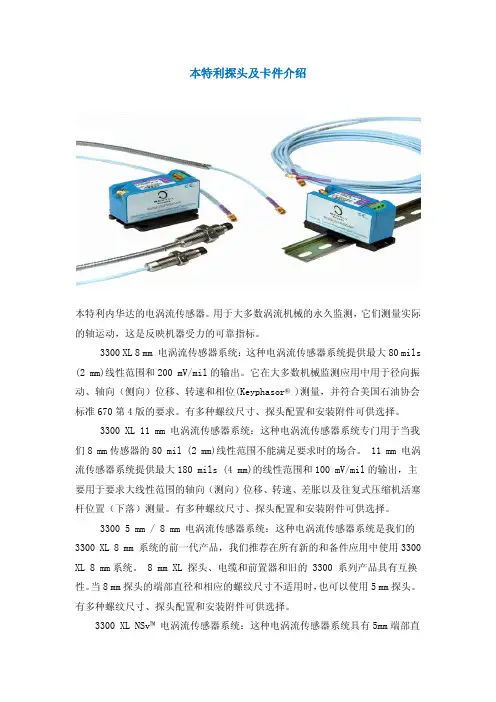
本特利探头及卡件介绍本特利内华达的电涡流传感器。
用于大多数涡流机械的永久监测,它们测量实际的轴运动,这是反映机器受力的可靠指标。
3300 XL 8 mm 电涡流传感器系统:这种电涡流传感器系统提供最大80 mils (2 mm)线性范围和200 mV/mil的输出。
它在大多数机械监测应用中用于径向振动、轴向(侧向)位移、转速和相位(Keyphasor® )测量,并符合美国石油协会标准670第4版的要求。
有多种螺纹尺寸、探头配置和安装附件可供选择。
3300 XL 11 mm 电涡流传感器系统:这种电涡流传感器系统专门用于当我们8 mm传感器的80 mil (2 mm)线性范围不能满足要求时的场合。
11 mm 电涡流传感器系统提供最大180 mils (4 mm)的线性范围和100 mV/mil的输出,主要用于要求大线性范围的轴向(测向)位移、转速、差胀以及往复式压缩机活塞杆位置(下落)测量。
有多种螺纹尺寸、探头配置和安装附件可供选择。
3300 5 mm / 8 mm 电涡流传感器系统:这种电涡流传感器系统是我们的3300 XL 8 mm 系统的前一代产品,我们推荐在所有新的和备件应用中使用3300 XL 8 mm系统。
8 mm XL 探头、电缆和前置器和旧的 3300 系列产品具有互换性。
当8 mm探头的端部直径和相应的螺纹尺寸不适用时,也可以使用5 mm探头。
有多种螺纹尺寸、探头配置和安装附件可供选择。
3300 XL NSv™ 电涡流传感器系统:这种电涡流传感器系统具有5mm端部直径和60 mils (1.5 mm)的更短线性范围,适用于被测靶面区域小、侧视或沉孔间隙减小以及其它限制使用我们标准的 5 mm / 8 mm 电涡流传感器的情况。
3300 16 mm 高温电涡流传感器系统:这种电涡流传感器系统用于最高350℃ (662°F)的高温环境,如温度超过我们标准电涡流探头和电缆能够承受的极限的某些燃气和蒸汽轮机应用。
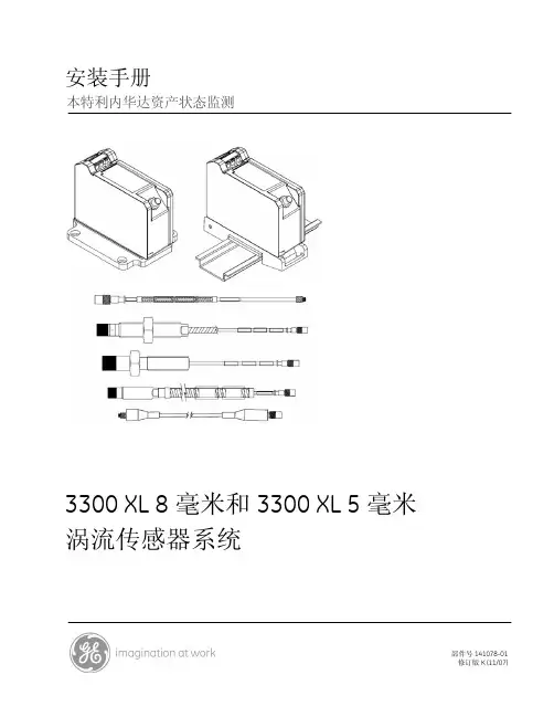
Specifications and Ordering InformationPart Number 141194-01Rev. T (12/12)Bently Nevada* Asset Condition Monitoring 3300 XL 8mm Proximity Transducer SystemDescription The 3300 XL 8 mm Proximity Transducer System consists of: ∙ One 3300 XL 8 mm probe,∙ One 3300 XL extension cable 1, and ∙ One 3300 XL Proximitor * Sensor 2. The system provides an output voltage that is directly proportional to thedistance between the probe tip and the observed conductive surface and can measure both static (position) and dynamic (vibration) values. The system’s primary applications are vibration and position measurements on fluid-film bearing machines, as well as Keyphasor * reference and speed measurements 3.The 3300 XL 8 mm system delivers the most advanced performance in our eddy current proximity transducer systems. The standard 3300 XL 8 mm 5-metre system also fully complies with the American Petroleum Institute’s (API) 670 Standard (4th Edition) for mechanical configuration, linear range, accuracy, and temperature stability. All 3300 XL 8 mm proximity transducer systems provide this level of performance and support complete interchangeability of probes, extension cables, and Proximitor sensors, eliminating the need to match or bench calibrate individual componentsEach 3300 XL 8 mm Transducer System component is backward-compatible and interchangeable 4 with other non-XL 3300 series 5 mm and 8 mm transducer system components 5. This compatibility includes the 3300 5 mm probe, for applications in which an 8 mm probe is too large for the available mounting space 6,7.Proximitor SensorThe 3300 XL Proximitor Sensor incorporates numerous improvements overprevious designs. Its physical packaging allows you to use it in high-density DIN-rail installations. You can also mount the sensor in a traditional panel mount configuration, where it shares an identical 4-hole mounting “footprint” with older Proximitor Sensor designs. The mounting base for either option provideselectrical isolation and eliminates the need for separate isolator plates. The 3300 XL Proximitor Sensor is highly immune to radio frequency interference, allowing you to install it in fiberglass housings without adverse effects from nearby radio frequency signals. The 3300 XL Proximitor Sensor’s improved RFI/EMI immunity satisfies European CE mark approvals without requiring special shielded conduit or metallic housings, resulting in lower installation costs and complexity. The 3300 XL’s SpringLoc terminal strips require no special installation tools and facilitate faster, more robust field wiring connections by eliminating screw-type clamping mechanisms that can loosen.Proximity Probe and Extension CableThe 3300 XL probe and extension cable also reflect improvements over previous designs. A patented TipLoc* molding method provides a more robust bond between the probe tip and the probe body. The probe’s cable incorporates a patented CableLoc* design that provides 330 N (75 lbf) pull strength to more securely attach the probe cable and probe tip. You can also order 3300 XL 8 mm probes and extension cables with an optional FluidLoc* cable option. This option prevents oil and other liquids from leaking out of the machine through the cable’s interior.ConnectorsThe 3300 XL probe, extension cable, and Proximitor sensor have corrosion-resistant, gold-plated ClickLoc* connectors. These connectors require only finger-tight torque (the connectors will "click" when tight), and the specially-engineered locking mechanism prevents the connectors from loosening. These connectors require no special tools for installation or removal.You can order the 3300 XL 8 mm probes and extension cables with connector protectors already installed. We can also supply connector protectors separately for field installations (such as when an application must run the cable through restrictive conduit). We recommend connector protectors for all installations to provide increased environmental protection8.Extended Temperature Range ApplicationsAn extended temperature range (ETR) probe and ETR extension cable are available for applications in which either the probe lead or extension cable may exceed the standard 177 ︒C (350 ︒F) temperature specification. The ETR probe has an extended temperature rating for up to 218 ︒C (425 ︒F). The ETR extension cable rating is up to 260 ︒C (500 ︒F). Both the ETR probe and cable are compatible with standard temperature probes and cables, for example, you can utilize an ETR probe with the 330130 extension cable. The ETR system uses the standard 3300 XL Proximitor Sensor. Note that when you use any ETR component as part of your system, the ETR component limits the system accuracy to the accuracy of the ETR system. Description Notes:1.1-metre systems do not use an extension cable.2.Proximitor sensors are supplied by default from thefactory calibrated to AISI 4140 steel. Calibration toother target materials is available upon request.3.Consult Bently Nevada* Applications Note,Considerations when using Eddy Current ProximityProbes for Overspeed Protection Applications, whenconsidering this transducer system for tachometer or overspeed measurements.4.3300 XL 8 mm components are both electrically andphysically interchangeable with non-XL 3300 5 mmand 8 mm components. Although the packaging ofthe 3300 XL Proximitor Sensor differs from itspredecessor, its design fits in the same 4-holemounting pattern when used with the 4-holemounting base, and will fit within the same mounting space specifications (when minimum permissiblecable bend radius is observed).5.Mixing XL and non-XL 3300-series 5 mm and 8 mmsystem components limits system performance to the specifications for the non-XL 3300 5 mm and 8 mmTransducer System.6.The 3300-series 5 mm probe (refer to Specificationsand Ordering Information p/n 141605-01) usessmaller physical packaging, but does not reduce theside view clearances or tip-to-tip spacingrequirements as compared to an 8 mm probe. It isused when physical (not electrical) constraintspreclude the use of an 8 mm probe. When yourapplication requires narrow side view probes, use the 3300 NSv* Proximity Transducer System (refer toSpecifications and Ordering Information p/n 147385-01).7.8 mm probes provide a thicker encapsulation of theprobe coil in the molded PPS plastic probe tip. Thisresults in a more rugged probe. The larger diameterof the probe body also provides a stronger, morerobust case. We recommend that you use 8 mmprobes when possible to provide optimal robustnessagainst physical abuse.8.Each 3300 XL extension cable includes silicone tapethat you can use instead of connector protectors. We do not recommend silicone tape for applications that will expose the probe-to-extension cable connectionto turbine oil.Specifications and Ordering InformationSpecificationsUnless otherwise noted, the following specifications are for a 3300 XL 8 mm Proximitor Sensor, extension cable and 8 mm probe between +18 ︒C and +27 ︒C (+64 ︒F to +80 ︒F), with a -24 Vdc power supply, a 10 kΩ load, an AISI 4140 steel target, and a probe gapped at 1.27 mm (50 mils). Performance characteristics apply to systems that consist solely of 3300 XL 8 mm components. The system accuracy and interchangeability specifications do not apply to transducer systems that are calibrated to any target other than our AISI 4140 steel target.ElectricalProximitorSensor InputAccepts one non-contacting3300-series 5 mm, 3300 8 mm or3300 XL 8 mm Proximity Probeand Extension Cable.PowerRequires -17.5 Vdc to -26 Vdcwithout barriers at 12 mAmaximum consumption, -23 Vdcto -26 Vdc with barriers.Operation at a more positivevoltage than -23.5 Vdc can resultin reduced linear range.SupplySensitivityLess than 2 mV change in outputvoltage per volt change in inputvoltage.OutputResistance50 ΩNominal ProbeDC ResistanceResistance (R PROBE) from CenterConductor to Outer ConductorProbe Length R PROBE (Ω)0.5 7.45± 0.501.0 7.59 ± 0.501.5 7.73± 0.502.0 7.88 ± 0.503.0 8.17 ± 0.605.0 8.73± 0.709.0 9.87 ± 0.90 NominalExtension CableDC ResistanceResistance (R CORE) from CenterConductor to Center ConductorLength of ExtensionCable (m)R CORE (Ω)3.0 0.66± 0.103.5 0.77 ± 0.124.0 0.88± 0.134.5 0.99 ± 0.156.0 1.32± 0.217.0 1.54± 0.237.5 1.65 ± 0.258.0 1.76± 0.268.5 1.87 ± 0.28Resistance (R JACKET) from OuterConductor to Outer ConductorLength of ExtensionCable (m)R JACKET (Ω)3.0 0.20± 0.043.5 0.23 ± 0.054.0 0.26± 0.054.5 0.30 ± 0.066.0 0.39± 0.087.0 0.46± 0.097.5 0.49 ± 0.108.0 0.53± 0.118.5 0.56 ± 0.11Specifications and Ordering InformationExtension CableCapacitance69.9 pF/m (21.3 pF/ft) typical Field Wiring0.2 to 1.5 mm2(16 to 24 AWG) .Recommend using 3-conductorshielded triad cable and tinnedfield wiring. Maximum length of305 metres (1,000 feet) betweenthe 3300 XL Proximitor Sensorand the monitor. See thefrequency response graphs inthrough Figure 13 (pages 28 and29) for signal rolloff at highfrequencies when using longerfield wiring lengths.Linear Range2 mm (80 mils). Linear rangebegins at approximately 0.25 mm(10 mils) from target and is from0.25 to 2.3 mm (10 to 90 mils)(approximately –1 to –17 Vdc). RecommendedGap Setting forRadial Vibration-9Vdc [approximately 1.27 mm(50 mils)]IncrementalScale Factor(ISF)Standard 5-or 1- metreSystem:7.87 V/mm (200 mV/mil) ± 5%including interchangeability errorwhen measured in increments of0.25 mm (10 mils) over the 80 millinear range from 0 °C to +45 °C(+32 °F to +113 °F).Standard9-metreSystem:7.87 V/mm (200 mV/mil) ± 6.5%including interchangeability errorwhen measured in increments of0.25 mm (10 mils) over the 80 millinear range from 0 °C to +45 °C(+32 °F to +113 °F).ExtendedTemperatureRange (ETR)for 5- and9-MetreSystems:7.87 V/mm (200 mV/mil) ± 6.5%including interchangeability errorwhen measured in increments of0.25 mm (10 mils) over the 80 millinear range from 0 °C to +45 °C(+32 °F to +113 °F).Deviation from best fit straight line (DSL)Standard 5-or 1-metreSystem:Less than ±0.025 mm (±1 mil) withcomponents at 0 °C to +45 °C(+32 °F to +113 °F).Standard9-metreSystem:Less than ±0.038 mm (±1.5 mil)with components at 0 °C to +45°C (+32 °F to +113 °F).ExtendedTemperatureRange 5 and9-metreSystems:Less than ±0.038 mm (±1.5 mil)with components at 0 °C to +45°C (+32 °F to +113 °F). PerformanceOver ExtendedTemperaturesStandard 5-or 1-metreSystem:Over a probe temperature rangeof –35 °C to +120 °C (-31 °F to+248 °F) with the Proximitorsensor and extension cablebetween 0 °C to +45°C (+32 °F to+113 °F), the ISF remains within±10% of 7.87 V/mm (200 mV/mil)and the DSL remains within±0.076 mm (±3 mils).Specifications and Ordering InformationOver a Proximitor sensor andextension cable temperaturerange of –35 °C to +65 °C (-31 °Fto +149 °F) with the probebetween 0 °C to +45 °C (+32 °F to+113 °F), the ISF remains within±10% of 7.87 V/mm (200 mV/mil)and the DSL remains within±0.076 mm (±3 mils).Standard9-metreSystem:Over a probe temperature rangeof –35 °C to +120 °C (-31 °F to+248 °F) with the Proximitorsensor and extension cablebetween 0 °C to +45°C (+32 °F to+113 °F), the ISF remains within±18% of 7.87 V/mm (200 mV/mil)and the DSL remains within±0.152 mm (±6 mils).Over a Proximitor sensor andextension cable temperaturerange of –35 °C to +65 °C (-31 °Fto +149 °F) with the probebetween 0 °C to +45 °C (+32 °F to+113 °F), the ISF remains within±18% of 7.87 V/mm (200 mV/mil)and the DSL remains within±0.152 mm (±6 mils).ExtendedTemperatureRange 5 and9-metreSystems:Over a probe and extension cabletemperature range of –35 °C to+260 °C (-31 °F to +500 °F) withthe Proximitor sensor between 0°C to +45 °C (+32 °F to +113 °F),the ISF remains within ±18% of7.87 V/mm (200 mV/mil) and theDSL remains within ±0.152 mm(±6 mils).FrequencyResponse(0 to 10 kHz), +0, -3 dB, with up to305 metres (1000 feet) of fieldwiring. MinimumTarget Size15.2 mm (0.6 in) diameter (flattarget)Shaft DiameterMinimum:50.8 mm (2 in)RecommendedMinimum:76.2 mm (3 in)When gapped at the center of thelinear range, the interactionbetween two separate transducersystems (cross-talk) will be lessthan 50 mV on shaft diameters ofat least 50 mm (2 in) or greater.You should take care to maintainminimum separation oftransducer tips, generally at least40 mm (1.6 in) for axial positionmeasurements or 38 mm (1.5 in)for radial vibration measurementsto limit cross-talk to 50 mV or less.Radial vibration or positionmeasurements on shaftdiameters smaller than 76.2 mm(3 in) will generally change thescale factor.Effects of 60 HzMagnetic Fieldsup to 300 GaussOutput Voltage in Mil pp/Gauss Gap(mil)5- or1-metreProximitorSensor9-metreProximitorSensorProbeExt.Cable10 0.0119 0.0247 0.0004 0.000450 0.0131 0.0323 0.0014 0.001490 0.0133 0.0348 0.0045 0.0045Specifications and Ordering InformationSpecifications and Ordering InformationCompliance and CertificationsEMCEuropean Community Directives: EMC Directive 2004/108/EC Standards:EN61000-6-2 EN61000-6-4MaritimeABS 2009 Steel Vessels Rules 1-1-4/7.7, 4-8-3/1.11.1, 4-9-7/13Hazardous Area ApprovalsNote: Multiple approvals for hazardous areas certified byCanadian Standards Association (C/US) in North America and by Baseefa for Europe and IEC Ex.Field Wiring Limitations:Type Approval: Gas GroupCapacitance(µF)Inductance (mH)L/R Ratio (μH/Ω)ATEX and IEC Zone 0/1IIC 0.078 0.99 29.2IIB 0.645 7.41 117.0IIA 2.144 15.6 234.0 CSA Div 1A &B 0.070 1.0 29.2C 0.600 5.0 117.0D 2.09 11.0 234.0CSA Div 2 All 0.460 100.0 N/A North America3300 XL Proximitor Sensor and probe, ia:Ex ia IIC T4/T5; Class I Zone 0 or Class 1; Groups A, B, C, and D, Class II, Groups E, F and G, Class III when installed with intrinsically safe zener barriers per drawing 141092 or when installed with galvanic isolators.3300 XL Proximitor Sensor and probe, nA:Ex nA IIC T4/T5 Class I Zone 2 or Class I, Division 2, Groups A, B, C, and D, when installed without barriers per drawing 140979. T 5 @ T a = -35 ︒C to +85 ︒C. T4 @ Ta= -51 ︒C to +100 ︒C.Europe3300 XL Proximitor Sensor, ia :II 1 G EEx ia IIC T4/T5 when installed per drawing 141092.3300 XL Proximitor Sensor, nA:II 3 G Ex nA II T4/T5 when installed per drawing 140979. T5 @ Ta= -35 ︒C to +85 ︒C T4 @ Ta= -51 ︒C to +100 ︒C3300 XL 8mm probe, ia: II 1 G EEx ia IIC, Temperature Classification per Table 1 when installed per drawing 142491. 3300 XL 8mm probe, nA:II 3 G EEx nA II, Temperature Classification per Table 1 when installed per drawing 142491.Brazil3300 XLProximitorSensor, ia:BR-Ex ia IIC T4(-51°C ≤ Ta ≤ +100°C)BR-Ex ia IIC T5(-35°C ≤ Ta ≤ +85°C)Terminal J1Terminal J2Ui= -28V Ii= 140mA Pi= 0.91W Ci = 0 FLi =0 H Uα= -28V Iα= 140mA Pα= 0.91W Ci = 0 FLi =0 .7 mHApplicable for Part numbers:330180, 330980, 330780, 330850,330878.3300 XL8mm and3300 5mmEddy CurrentProbes, ia:BR-Ex ia IIC TemperatureClassification per Table 1.Ui = -28V Ci = 0 FIi = 140 mA Li = 0 HPi = 0.91 WIEC Ex3300 XLProximitorSensor, ia:Ex ia IIC T4 (-51°C ≤ Ta ≤ +100°C) /T5 (-35ºC ≤ Ta ≤ +85ºC)Ui= -28V Ci = 0Ii= 140mA Li =10µHPi= 0.84W3300 XLProximitorSensor, nA:Ex nA II T4 (-51°C ≤ Ta ≤ +100°C) /T5 (-35°C ≤ Ta ≤ +85°C)Ui = -28V3300 XL8mm and3300 5mmEddy CurrentProbes, ia:Ex ia IIC TemperatureClassification per Table 1.Ui = -28V Ci = 1.5 nFIi = 140 mA Li = 200 µHPi = 0.84 W3300 XL8mm and3300 5mmEddy CurrentProbes, nA:Ex nA II for Zone 2 TemperatureClassification per Table 1.Table 1: Probe Temperature ClassificationTemperatureClassificationAmbient Temperature(Probe Only)T1 -51ºC to +232ºCT2 -51ºC to +177ºCT3 -51ºC to +120ºCT4 -51ºC to +80ºCT5 -51ºC to +40ºCHazardous AreaConditions ofSafe Use:ATEX:Follow the conditions of safe useincluded on the Declaration ofConformance sent with eachproduct.CanadianStandardsAssociation(CSA):Division 1 (Intrinsically safe):Install per Bently Nevada drawing141092.Division 2 (non-Incendive): Installper Bently Nevada drawing140979.Specifications and Ordering InformationIECEx:Zone 0 (Intrinsically safe): TheProximitor Sensor must beinstalled to minimize the risk ofimpact or friction with othermetallic surfaces.Zone 2 (non-Incendive): Theprobe must be supplied from avoltage-limited source. MechanicalProbe TipMaterialPolyphenylene sulfide (PPS). Probe CaseMaterialAISI 303 or 304 stainless steel(SST).Probe CableSpecificationsStandardcable:75Ω triaxial, fluoroethylenepropylene (FEP) insulated probecable in the following total probelengths: 0.5, 1, 1.5, 2, 3, 5, or 9metres.ExtendedTemperatureRange cable:75Ω triaxial, perfluoroalkoxy (PFA)insulated probe cable in thefollowing total probe lengths: 0.5,1, 1.5, 2, 5, or 9 metres.Armor(optional onboth):Flexible AISI 302 or 304 SST withFEP outer jacket.Tensile Strength(MaximumRated):330 N (75 lbf) probe case to probelead.270 N (60 lbf) at probe lead toextension cable connectors.ConnectorMaterial:Gold-plated brass or gold-platedberyllium copper.Probe CaseTorque:Probe TypeMaximumRatedRecommended Standardforward-mountedprobes33.9 N∙m(300 in∙lbf)11.2 N∙m(100 in∙lbf) Standard forward-mount probes -first three threads22.6 N∙m(200 in∙lbf)7.5 N∙m(66 in∙lbf)Reverse-mountprobes22.6 N∙m(200 in∙lbf)7.5 N∙m(66 in∙lbf)Extension CableMaterialStandardcable:75Ω triaxial, fluoroethylenepropylene (FEP) insulated.ExtendedTemperatureRange cable:75Ω triaxial, perfluoroalkoxy (PFA)insulated.MinimumCable BendRadius:25.4 mm (1.0 in)Note: 3300 XL 8 mm components are both electrically and physically interchangeable with non-XL 3300 5 mm and 8mm components when minimum permissible cable bendradius is observed..Specifications and Ordering InformationConnectorMaterial:Gold-plated brass or gold-platedberyllium copper.MaximumConnectorTorque:0.565 N∙m (5 in∙lbf) Connector-to-connectorrecommendedtorque:Connector Type Tightening Instructions Two 3300 XL gold"click" typeconnectorsFinger tightOne non-XL stainlesssteel connector and one 3300 XLconnector Finger tight plus 1/8 turnusing pliersProximitorSensor MaterialA308 aluminumConnectorMaterial:Gold-plated brass or gold-platedberyllium copper.System Length5 or 9 metres (including extensioncable) or 1 metre (probe only). Total SystemMass (Typical)0.7 kg (1.5 lbm)Probe:323 g (11.4 oz)ExtensionCable:34 g/m (0.4 oz/ft)ArmoredExtensionCable:103 g/m (1.5 oz/ft)ProximitorSensor:246 g (8.67 oz) Environmental LimitsProbe Temperature RangeOperating andStorageTemperatureStandardProbe:-51 °C to +177 °C (-60 °F to +350°F)ExtendedTemperatureRange Probe:-51 °C to +218 °C (-60 °F to+425°F) for the probe tip; -51 °C to+260 °C (-60 °F to +500 °F) for theprobe cable and connector. Note: Exposing the probe to temperatures below –34 ︒C (-30 ︒F) may cause premature failure of the pressure seal. Probe Pressure3300 XL 8 mm probes aredesigned to seal differentialpressure between the probe tipand case. The probe sealingmaterial consists of a Viton®O-ring. Probes are not pressuretested prior to shipment. Contactour custom design department ifyou require a test of the pressureseal for your application.Note: It is the responsibility of the customer or user to ensure that all liquids and gases are contained and safelycontrolled should leakage occur from a proximity probe.In addition, solutions with high or low pH values mayerode the tip assembly of the probe causing medialeakage into surrounding areas. Bently Nevada, Inc. willnot be held responsible for any damages resulting fromleaking 3300 XL 8 mm proximity probes. In addition, 3300XL 8 mm proximity probes will not be replaced under theservice plan due to probe leakage.Specifications and Ordering InformationExtension Cable Temperature Range Operating andStorageTemperatureStandardCable:-51 °C to +177 °C (-60 °F to +350°F)ExtendedTemperatureRange Cable:-51 °C to +260 °C (-60 °F to +500°F)Proximitor Sensor Temperature Range OperatingTemperature-51 °C to +100 °C (-60 °F to +212°F)StorageTemperature-51 °C to +105 °C (-60 °F to +221°F)RelativeHumidityLess than a 3% change inAverage Scale Factor (ASF) whentested in 93% humidity inaccordance with IEC standard68-2-3 for up to 56 days. PatentsComponents or proceduresdescribed in one or more of thefollowing patents apply to thisproduct: 5,016,343; 5,126,664;5,351,588; and 5,685,884.Specifications and Ordering InformationOrdering Information Probes3300 XL 8 mm Proximity Probes:330101 3300 XL 8 mm Probe, 3/8-24 UNF thread, without armor2330102 3300 XL 8 mm Probe, 3/8-24 UNF thread, with armor2Part Number-AXX-BXX-CXX-DXX-EXXA:Unthreaded Length OptionNote: Unthreaded length must be at least 0.8 inches less than the case length.Order in increments of 0.1 inLength configurations:Maximum unthreaded length: 8.8 inMinimum unthreaded length: 0.0 inExample:0 4 = 0.4 inB:Overall Case Length OptionOrder in increments of 0.1 inThreaded length configurations:Maximum case length: 9.6 inMinimum case length: 0.8 inExample:2 4 = 2.4 inC:Total Length Option0 50.5 metre (1.6 feet)1 0 1.0 metre (3.3 feet)1 5 1.5 metre (4.9 feet)2 0 2.0 metres (6.6 feet)3 0 3.0 metres (9.8 feet)5 0 5.0 metres (16.4 feet)9 09.0 metres (29.5 feet)Notes: 3-metre length option is only available on 330101 probes, and are designed for use with the 9-metre Proximitorsensor only.5-metre probes are designed for use with the 5-metreProximitor sensor only.D:Connector and Cable-Type Option0 1Miniature coaxial ClickLocconnector with connectorprotector, standard cable0 2 Miniature coaxial ClickLocconnector, standard cable1 1Miniature coaxial ClickLocconnector with connectorprotector, FluidLoc cable1 2Miniature coaxial ClickLocconnector, FluidLoc cable E:Agency Approval Option0 0 Notrequired0 5 MultipleApprovals 3300 XL 8 mm Proximity Probes, Metric: 330103 3300 XL 8 mm Probe, M10 x 1 thread, without armor2330104 3300 XL 8 mm Probe, M10 x 1 thread, with armor2Part Number-AXX-BXX-CXX-DXX-EXXA:Unthreaded Length OptionNote: Unthreaded length must be at least 20 mm less than the case length.Order in increments of 10 mm.Length configuration:Maximum unthreaded length: 230mmMinimum unthreaded length: 0 mmExample:0 6 = 60 mmB:Overall Case Length OptionOrder in increments of 10 mm.Metric thread configurations:Maximum length: 250 mmMinimum length: 20 mmExample:0 6 = 60 mmC:Total Length Option0 50.5 metre (1.6 feet)1 0 1.0 metre (3.3 feet)1 5 1.5 metres (4.9 feet)2 0 2.0 metres (6.6 feet)5 0 5.0 metres (16.4 feet)Note: 5-metre probes are designed for use with the 5-metre Proximitor sensor only.9 09.0 metres (29.5 feet)D: Connector and Cable-Type Option0 1 Miniature coaxial ClickLocconnector with connectorprotector, standard cable0 2 MiniaturecoaxialClickLocconnector, standard cable1 1 MiniaturecoaxialClickLocconnector with connectorprotector, FluidLoc cable1 2 MiniaturecoaxialClickLocconnector, FluidLoc cable E:Agency Approval Option0 0 Not required0 5 MultipleApprovalsSpecifications and Ordering Information3300 XL 8 mm Reverse Mount Probes330105-02-12-CXX-DXX-EXX, 3/8-24 UNF threads2 330106-05-30-CXX-DXX-EXX, M10 x 1 threads2Option DescriptionsC:Total Length Option0 50.5 metre (1.6 feet)1 0 1.0 metre (3.3 feet)1 5 1.5 metre (4.9 feet)2 0 2.0 metres (6.6 feet)5 0 5.0 metres (16.4 feet)Note: 5-metre probes are designed for use with the 5-metre Proximitor sensor only.9 09.0 metres (29.5 feet)D: Connector Option0 2 MiniatureClickLoccoaxialconnector1 2 MiniatureClickLoccoaxialconnector, FluidLoc cable Note: The FluidLoc cable option –12 is not necessary on the vast majority of 330105 and 330106 installations due to thepresence of the probe sleeve. Consider carefully theapplication before ordering the FluidLoc cable option forthese probes.E:Agency Approval Option0 0 Notrequired0 5 MultipleApprovals 3300 XL 8 mm Proximity Probes, Smooth Case: 330140 3300 XL 8 mm Probe without armor1330141 3300 XL 8 mm Probe with armor1Part Number-AXX-BXX-CXX-DXXOption DescriptionsA:Overall Case Length OptionOrder in increments of 0.1 inLength configurations:Maximum length: 9.6 inMinimum length: 0.8 inExample:2 4 = 2.4 inB:Total Length Option0 50.5 metre (1.6 feet)1 0 1.0 metre (3.3 feet)1 5 1.5 metres (4.9 feet)2 0 2.0 metres (6.6 feet)5 0 5.0 metres (16.4 feet)Note: 5-metre probes are designed for use with the 5-metre Proximitor sensor only.9 09.0 metres (29.5 feet) C:Connector and Cable-Type Option0 1 MiniaturecoaxialClickLocconnector with connectorprotector, standard cable0 2 MiniaturecoaxialClickLocconnector, standard cable1 1 MiniaturecoaxialClickLocconnector with connectorprotector, FluidLoc cable1 2 MiniaturecoaxialClickLocconnector, FluidLoc cable D:Agency Approval Option0 0 Not required0 5 MultipleApprovals 3300 XL 8 mm Extended Temperature Range (ETR) Proximity Probes:330191 3300 XL 8 mm ETR Probe, 3/8-24 UNF thread, without armor330192 3300 XL 8 mm ETR Probe, 3/8-24 UNF thread, with armorPart Number-AXX-BXX-CXX-DXXA:Unthreaded Length OptionNote: Unthreaded length must be at least 0.8 inches less than the case length.Order in increments of 0.1 inLength configurations:Maximum unthreaded length: 8.8 inMinimum unthreaded length: 0.0 inExample:1 5 = 1.5 inB:Overall Case Length OptionOrder in increments of 0.5 inThreaded length configurations:Maximum case length: 9.6 inMinimum case length: 0.8 inExample:2 5 = 2.5 inC:Total Length Option0 50.5 metre (1.6 feet)1 0 1.0 metre (3.3 feet)1 5 1.5 metre (4.9 feet)2 0 2.0 metres (6.6 feet)5 0 5.0 metres (16.4 feet)Note: 5-metre probes are designed for use with the 5-metre Proximitor sensor only.9 09.0 metres (29.5 feet)D:Agency Approval Option0 0 Notrequired0 5 MultipleApprovalsSpecifications and Ordering Information。


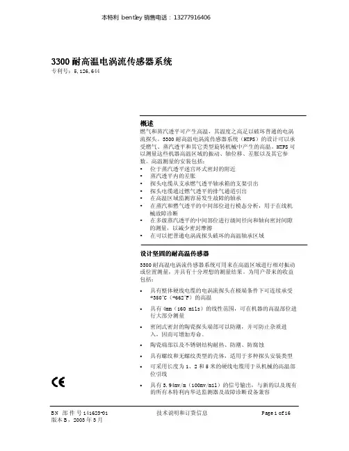
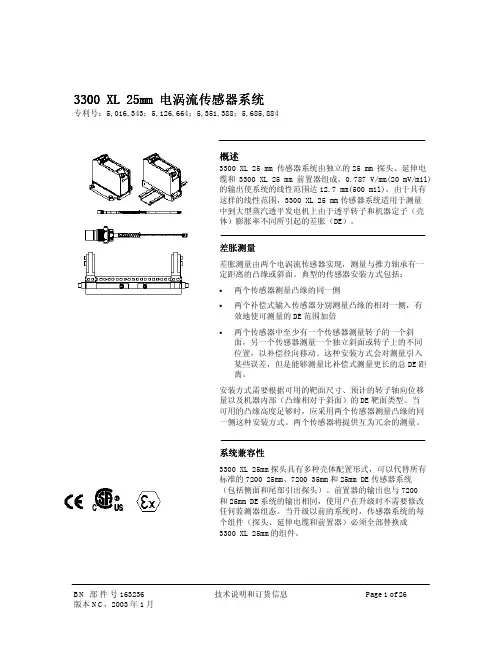
BH5000网络化实时监测诊断系统 ====使用指南 ====版本:V4.6.0.4北京博华信智科技发展有限公司2014年 04月目录1前言 .................................................................................................................. 1 1.1标识 (2)1.2BH5000网络化实时监测系统概 ................................................................... 2 1.2.1实时监测系统功能 .......................................................................................... 2 1.2.2实时监测系统特性 (3)1.3BH5000客户端软件概述 (4)2客户端软件的安装和配置 .............................................................................. 5 2.1客户端软件的安装 (5)2.2客户端软件的配置 (7)3基本操作指南 ................................................................................................ 10 3.1系统登录 ........................................................................................................ 10 3.2界面总览 ........................................................................................................ 10 3.3菜单栏 ............................................................................................................ 11 3.4快捷工具栏 .................................................................................................... 13 3.5功能模块抽屉式菜单栏 ................................................................................ 14 3.6导航栏 ............................................................................................................ 15 3.7绘图工具栏 .................................................................................................... 15 3.8操作页 ............................................................................................................ 16 3.9信息页 ............................................................................................................ 16 3.10图谱操作 ........................................................................................................ 17 3.10.1图谱新增毫秒显示 ........................................................................................ 17 3.10.2游标 ................................................................................................................ 17 3.10.3标注 ................................................................................................................ 17 3.10.4同步标注 ........................................................................................................ 18 3.10.5标点 ................................................................................................................ 18 3.10.6趋势操作 ........................................................................................................ 19 3.10.7复位 ................................................................................................................ 19 3.10.8打印 ................................................................................................................ 20 3.10.9保存图形 ........................................................................................................ 20 3.10.10切换 ................................................................................................................ 21 3.10.11显示报警线 .................................................................................................... 22 3.10.12纵坐标自动调整 ............................................................................................ 22 3.10.13锁定坐标 ........................................................................................................ 23 3.10.14手动修改坐标 (23)3.10.15图谱放大,关联更新 (24)3.10.16滚轮放大 (24)3.10.17自定义图谱布局 (25)3.10.18三维图谱 (26)3.10.19双击时间戳画图 (27)3.11设备树显示报警 ............................................................................................ 27 3.12设备树启停车状态显示 ................................................................................ 27 3.13设备树显示断网状态 .................................................................................... 28 3.14设备切换 ........................................................................................................ 28 3.15背景提示图 .................................................................................................... 29 3.16服务器状态切换 .. (30)3.17设备采集状态设置 (33)4旋转机械专用图谱 ........................................................................................ 34 4.1机组概貌图 .................................................................................................... 34 4.2振动监测 ........................................................................................................ 35 4.3振动历史比较图 ............................................................................................ 37 4.4单多值棒图 .................................................................................................... 38 4.5轴心轨迹 ........................................................................................................ 39 4.6轴心位置 ........................................................................................................ 42 4.7启停车图形 .................................................................................................... 43 4.8综合分析 ........................................................................................................ 45 4.9运行状态图 .................................................................................................... 49 4.10其它参数趋势图 ............................................................................................ 51 4.11全频谱 ............................................................................................................ 52 4.12二维全息谱图 ................................................................................................ 53 4.13三维全息谱图 ................................................................................................ 54 4.14旋转报警查询 (55)4.15现场动平衡 (57)5临时在线专用图谱 ........................................................................................ 59 5.1机组概貌图 .................................................................................................... 59 5.2动平衡响应分析 ............................................................................................ 59 5.3试车分析 ........................................................................................................ 60 5.4振动监测 ........................................................................................................ 62 5.5振动历史比较图 ............................................................................................ 62 5.6单多值棒图 (62)5.7轴心轨迹 (63)5.8轴心位置 ........................................................................................................ 63 5.9综合分析 ........................................................................................................ 63 5.10运行状态图 .................................................................................................... 63 5.11其他参数趋势图 ............................................................................................ 63 5.12旋转报警查询 ................................................................................................ 63 5.13全频谱图 ........................................................................................................ 63 5.14二维全息谱图 ................................................................................................ 63 5.15三维全息谱图 ................................................................................................ 63 5.16现场动平衡 (64)5.17倒谱图 (64)6往复机械专用图谱 ........................................................................................ 64 6.1机组概貌图 .................................................................................................... 64 6.2运行状态图 .................................................................................................... 65 6.3历史比较图 .................................................................................................... 67 6.4单值棒图 ........................................................................................................ 68 6.5活塞杆沉降 /偏摆监测 .................................................................................. 70 6.6活塞杆轨迹图 ................................................................................................ 71 6.7振动监测 ........................................................................................................ 72 6.8多参数分析 .................................................................................................... 74 6.9示功图 ............................................................................................................ 75 6.10综合监测 ........................................................................................................ 76 6.11其它参数趋势图 ............................................................................................ 77 6.12往复报警查询 ................................................................................................ 79 6.13应力监测 (80)6.14冲击诊断 (81)7风电专用图谱 ................................................................................................ 83 7.1机组概貌图 .................................................................................................... 83 7.2趋势分析 ........................................................................................................ 84 7.3冲击诊断 ........................................................................................................ 86 7.4转子类故障诊断 ............................................................................................ 89 7.5倒谱图 ............................................................................................................ 90 7.6单多值棒图 .................................................................................................... 92 7.7其它参数趋势图 ............................................................................................ 93 7.8风电报警查询 (94)8机泵专用图谱 ................................................................................................ 95 8.1机组概貌图 .................................................................................................... 96 8.2趋势分析 ........................................................................................................ 97 8.3冲击诊断 ........................................................................................................ 98 8.4转子类故障诊断 .......................................................................................... 101 8.5倒谱图 .......................................................................................................... 103 8.6单多值棒图 .................................................................................................. 104 8.7其它参数趋势图 (105)8.8机泵报警查询 (106)9在线报告报表 .............................................................................................. 108 9.1监测诊断报告 .............................................................................................. 108 9.2机组月报表 .................................................................................................. 110 9.3厂级报表 ...................................................................................................... 113 9.4振动参数报表 .............................................................................................. 113 10案例库模块 .................................................................................................. 115 10.1案例录入 ...................................................................................................... 115 10.1.1添加案例 ...................................................................................................... 117 10.1.2修改案例 ...................................................................................................... 121 10.1.3取消案例 ...................................................................................................... 121 10.2案例查询 ...................................................................................................... 121 10.2.1案例查询 ...................................................................................................... 122 10.2.2导出word .................................................................................................... 122 10.3案例审核 ...................................................................................................... 123 10.3.1案例查询 ...................................................................................................... 123 10.3.2修改案例 ...................................................................................................... 124 10.3.3审核案例 ...................................................................................................... 124 10.4检维修记录管理 .......................................................................................... 125 10.4.1添加检维修记录 .......................................................................................... 126 10.4.2修改检维修记录 .......................................................................................... 126 10.4.3删除检维修记录 .......................................................................................... 126 10.4.4导出word .................................................................................................... 127 10.5开停车记录管理 .......................................................................................... 127 10.5.1查询原始开停车记录 .................................................................................. 127 10.5.2添加开停车记录 .......................................................................................... 128 10.5.3修改开停车记录 (128)10.5.4删除开停车记录 .......................................................................................... 128 10.5.5开停车记录查询 (129)10.6基于案例诊断 (129)10.6.1诊断条件 (129)10.6.2相似度判断 .................................................................................................. 129 11系统维护和系统故障诊断 .......................................................................... 130 11.1客户端无法登陆 .......................................................................................... 130 11.2客户端看不到概貌图 .................................................................................. 131 11.3客户端提示请选择测点 .............................................................................. 131 11.4添加图谱出错 .............................................................................................. 131 11.5客户端查看不到历史数据库或不保存历史数据 ...................................... 131 11.6客户端图谱单位不正确 .............................................................................. 132 11.7客户端测点缸号不正确 .............................................................................. 132 11.8客户端不报警 .............................................................................................. 132 12附录 .............................................................................................................. 132 12.1旋转机械振动机理和诊断方法 .................................................................. 133 12.1.1机械设备振动监测的主要参数和定义 ...................................................... 133 12.1.2机械设备振动分析常用手段 . (138)1前言状态监测与故障诊断是在设备运行中或在基本不拆卸的情况下, 通过各种手段,掌握设备的运行状态,判定设备产生故障的部位和原因,并预测、预报设备未来的运行状态。
本特利3300振动指示报警仪1序号仪器名称仪器型号仪器精度1 校验仪1045 0.12 24VDC稳压电源3 TK3-2校验仪23、校验方法:以校验振动值范围0-100um为例,选用8mm探头。
3.1 设备连接方式见下图:3.2 监测器功能3.2.1 OK指示---当前置器输出电压在其上下限之间时(BENTLY为-2——-18V,不同产品的OK电压有所差异,应以说明书为准),OK指示灯点亮,则定义相应传感器处于OK状态。
当A/B通道均处于OK状态或旁路状态时OK继电器才接通。
在周期自检出现异常时,OK指示灯以5Hz频率闪烁;如果上一次复位后传感器出现异常,则OK指示灯以1Hz频率闪烁。
3.2.2延时OK/通道失效——若某通道的信号输入不在OK值的上下限范围内,则该通道的OK LED熄灭,BYPASS LED接通,该通道被关闭;若信号输入恢复正常达30秒,则该通道的OK LED将以1Hz频率闪烁,表示OK状态恢复,BYPASS LED 熄灭并恢复监测功能。
3.2.3 BYPASS LED——若某通道一直处在非OK状态,操作人员可通过设置在监测器线路板上的通道旁路开关使该通道从系统中切除。
通道被旁路或处于延时OK/通道失效状态或用户启动自检,BYPASS LED点亮,该通道失去监测功能。
3.2.4间隙电压——按下面板上的GAP键,从表头的中间刻度读取通道A和B的间隙电压值。
同时按下面板上的GAP和ALERT键可显示间隙电压警告报警点的设置值。
当间隙电压达到或位于间隙电压范围的上限或下限之外并达到6秒时,ALERT LED就会发亮同时相应的警告报警继电器接点就会动作。
3.2.5 报警功能3.2.5.1报警点检查——按下面板上的ALERT和DANGER键,可检查各通道的警告和危险设定点的数值。
3.2.5.2第一报警——警告报警和危险报警具有各自的第一报警电路。
当框架中的监测器具有第一报警功能选择时,若某通道的警告或危险报警为在框架中最先发生,则其相应的报警LED会以闪亮的方式显示。
四川天华股份有限公司仪表工程部本特利3300监视仪检修手册文件编号:编制:熊怀军分发编号:审核:受控状态:批准:二OO八年5月编制本特利3300监视仪检修手册一、设备概述我公司大化肥装置的大型旋转设备----大机组,是大化肥装置的核心部件,它的正常与否将直接影响大化肥装置的正常运行。
大型机组的在线监视系统对机组的故障分析起着至关重要的作用。
本特利3300监视系统主要用于对大型旋转机械的轴位移、轴振动、轴转速等参数的长期实时监测,并可分析出设备的工作状况和故障原因,有效的对设备进行保护及进行预测性维修,防止毁灭性事故发生。
在我公司的各大机组都广泛使用了本特利3300系列监视仪来进行监测和保护,以下主要针对Bently公司3300系列介绍。
二、本特利3300监视仪简介1、型号规格本特利3300监视仪的型号有BN3300/16,BN3300/20,BN3300/12,BN3300/03BN3300的技术规格电源:220V AC,50/60HZ2、本特利3300监视系统的工作原理本特利Bently 3300监视系统由8mm趋近式探头传感器、延伸电缆、前置放大器和指示仪等组成。
这种探头表面有一个封闭传感器线圈,线圈高频工作电流探头前端产生一个交流磁场,当探头靠近转动轴时,轴表面将感应出电涡流,同时,闭合电涡流也轴表面感应出一个对应磁场,与探头线圈交变磁场作用相反,反作用磁场抵消作用,使探头产生交变磁场受到损耗,这种损耗能被前置放大器检测出来,这样,探头与轴面间隙就可以磁场耦合反映到前置放大器输出电压上,构成一定特性曲线关系[4]。
在测量位移时是主要将其直流分量进行放大;而在测量振动时主要将其交流分量进行放大,然后分别输入进BN3300/20,和BN3300/16 监视仪进行显示和报警。
其原理图如下。
探头传感器——前置器——BN3300系列监视仪---DSC及其它显示表3、本特利3300监视仪的构成本特利3300监视仪的构成由框架、电源卡、系统监视卡、振动监视卡、位移监视卡组成。
本特利探头调试要求本工程选用的是本特利3300XL系列探头、延长电缆、前置器(5米系统),它的灵敏度为7.87V/mm,关于探头、延长电缆、前置器的说明见附件。
1.当探头用于测量轴振动时:调试要求:探头与被测轴之间的间隙值为1.27mm (50mil),转换成电压值为-9.75Vdc。
调试过程:将探头、延长电缆和前置放大器连接好后,用万用表测量前置放大器的COM和OUT两个端子之间的电压,通过旋入/出探头将电压调整为-9.75Vdc即调整完毕。
2.当探头用于测量键相时:调试要求:探头与被测轴之间的间隙值为1.27mm (50mil),转换成电压值为-9.75Vdc。
调试过程:将探头、延长电缆和前置放大器连接好后,用万用表测量前置放大器的COM和OUT两个端子之间的电压,通过旋入/出探头将电压调整为-9.75Vdc即调整完毕。
3.当探头用于测量位移时:调试要求:探头与被测轴之间的间隙值为1.27mm (50mil),转换成电压值为-9.75Vdc。
调试过程:把轴打到轴窜量的中间位置,将探头、延长电缆和前置放大器连接好后,用万用表测量前置放大器的COM和OUT两个端子之间的电压,通过旋入/出探头将电压调整为-9.75Vdc即调整完毕,此时在控制室应显示位移值为0,误差不超过0.02mm。
注意事项:●调试时要先试一下探头安装位置的螺纹是否很轻松的旋入,如果旋入不畅,用对应的丝锥重新攻丝。
●调试时要用8/10的开口搬手和4”活搬手,不能使用过大的搬手,防止将探头拧断。
●调试键相时探头不能正对着键相凹槽,要远离键相凹槽。
●调试过程中要一直将万用表接入,保证一直能监测到间隙电压,间隙电压的变化趋势为-24VDC~0 VDC。
●调试位移时要保证转子在整个轴向间隙的中间位置,否则调试出的结果会有很大的误差。
●调试位移时要确认3500系统中组态的中性点电压为-9.75VDC。
●本特利的3300XL探头、延长电缆、前置器不同型号之间可以互换。