51单片机独立按键程序查询法和外部中断两种
- 格式:doc
- 大小:31.00 KB
- 文档页数:5
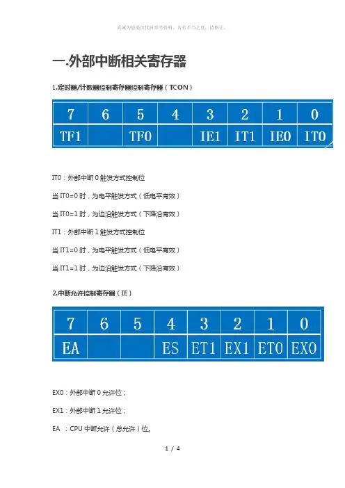
一.外部中断相关寄存器1.定时器/计数器控制寄存器控制寄存器(TCON)IT0:外部中断0触发方式控制位当IT0=0时,为电平触发方式(低电平有效)当IT0=1时,为边沿触发方式(下降沿有效)IT1:外部中断1触发方式控制位当IT1=0时,为电平触发方式(低电平有效)当IT1=1时,为边沿触发方式(下降沿有效)2.中断允许控制寄存器(IE)EX0:外部中断0允许位;EX1:外部中断1允许位;EA :CPU中断允许(总允许)位。
二.外部中断的处理过程1、设置中断触发方式,即IT0=1或0,IT1=1或02、开对应的外部中断,即EX0=1或EX1=1;3、开总中断,即EA=1;4、等待外部设备产生中断请求,即通过P3.2,P.3.3口连接外部设备产生中断5、中断响应,执行中断服务函数三.程序编写要求:通过两位按键连接外部中断0和1,设定外部中断0为下降沿触发方式,外部中断1为低电平触发方式,按键产生中断使数字加减,用一位共阳极数码管来显示数值。
目的:感受外部中断对程序的影响,体会低电平触发和下降沿触发的区别。
#include<reg51.h>#define uint unsigned int #define uchar unsigned char uchar code dat[]={0xc0,0xf9,0xa4,0xb0,0x99,0x92,0x82,0xf8,0x80,0x90}; uint num;void main(){EA=1; //开总中断IT0=1; //下降沿触发IT1=0; //低电平触发EX0=1; //外部中断0允许EX1=1; //外部中断1允许while(1){P0=dat[num%10];}}void plus() interrupt 0//外部中断0 {EX0=0;num++;EX0=1;}void minus() interrupt 2//外部中断1 {EX1=0;num--; EX1=1; }。

51单片机中断总结:1. 查询优先级为固定的(外部中断0>定时器0>外部中断1>定时器1>串行中断)。
2. 执行优先级可以通过IP寄存器进行设置(高/低)。
3. CPU同时收到多个中断请求时,首先响应优先级较高者,然后相应优先级较低者;如果优先级相同,则按照查询优先级顺序依次响应。
4. 正在执行的中断服务,不能被同级或更低级的中断请求打断,但会被更高级的中断请求打断。
推论(1)高优先级的中断不能被任何其它中断所打断(2)低优先级的中断只能在没有任何中断服务运行时得到响应。
5. 对于定时器和外部中断,在进入中断服务后,其中断标志位会自动清零;对于串行中断,由于有两个中断源,需要手动查询并清零RI或/和TI。
if (RI) {// processingRI = 0;}if (TI) {// processingTI = 0;}6. 如果是使用汇编写中断服务,需要保护累加器、状态寄存器、寄存器组等8051 Tutorial: Interrupts/tutint.phpAs the name implies, an interrupt is some event which interrupts normal program execution.As stated earlier, program flow is always sequential, being altered only by those instructions which expressly cause program flow to deviate in some way. However, interrupts give us a mechanism to "put on hold" the normal program flow, execute a subroutine, and then resume normal program flow as if we had never left it. This subroutine, called an interrupt handler, is only executed when a certain event (interrupt) occurs. The event may be one of the timers "overflowing," receiving a character via the serial port, transmitting a character via the serialport, or one of two "external events." The 8051 may be configured so that when any of these events occur the main program is temporarily suspended and control passed to a special section of code which presumably would execute some function related to the event that occured. Once complete, control would be returned to the original program. The main program never even knows it was interrupted.The ability to interrupt normal program execution when certain events occur makes it much easier and much more efficient to handle certain conditions. If it were not for interrupts we would have to manually check in our main program whether the timers had overflown, whether we had received another character via the serial port, or if some external event had occured. Besides making the main program ugly and hard to read, such a situation would make our program inefficient since wed be burning precious "instruction cycles" checking for events that usually dont happen.For example, lets say we have a large 16k program executing many subroutines performing many tasks. Lets also suppose that we want our program to automatically toggle the P3.0 port every time timer 0 overflows. The code to do this isnt too difficult:JNB TF0,SKIP_TOGGLECPL P3.0CLR TF0SKIP_TOGGLE: ...Since the TF0 flag is set whenever timer 0 overflows, the above code will toggle P3.0 every time timer 0 overflows. This accomplishes what we want, but is inefficient. The JNB instruction consumes 2 instruction cycles to determine that the flag is not set and jump over the unnecessary code. In the event that timer 0 overflows, the CPL and CLR instruction require 2 instruction cycles to execute. To make the math easy, lets say the rest of the code in the program requires 98 instruction cycles. Thus, in total, our code consumes 100 instruction cycles (98 instruction cycles plus the 2 that are executed every iteration to determine whether or not timer 0 has overflowed). If were in 16-bit timer mode, timer 0 will overflow every 65,536 machine cycles. In that time we would have performed 655 JNB tests for a total of 1310 instruction cycles, plus another 2 instruction cycles to perform the code. So to achieve our goal weve spent 1312 instruction cycles. So 2.002% of our time is being spent just checking when to toggle P3.0. And our code is ugly because we have to make that check every iteration of our main program loop.Luckily, this isnt necessary. Interrupts let us forget about checking for the condition. The microcontroller itself will check for the condition automatically and when the condition is met will jump to a subroutine (called an interrupt handler), execute the code, then return. In this case, our subroutine would be nothing more than:CPL P3.0RETIFirst, youll notice the CLR TF0 command has disappeared. Thats because when the 8051 executes our "timer 0 interrupt routine," it automatically clears the TF0 flag. Youll also notice that instead of a normal RET instruction we have a RETI instruction. The RETI instruction does the same thing as a RET instruction, but tells the 8051 that an interrupt routine has finished. You must always end your interrupt handlers with RETI.Thus, every 65536 instruction cycles we execute the CPL instruction and the RETI instruction. Those two instructions together require 3 instruction cycles, and weve accomplished the same goal as the first example that required 1312 instruction cycles. As far as the toggling of P3.0 goes, our code is 437 times more efficient! Not to mention its much easier to read and understand because we dont have to remember to always check for the timer 0 flag in our main program. We just setup the interrupt and forget about it, secure in the knowledge that the 8051 will execute our code whenever its necessary.The same idea applies to receiving data via the serial port. One way to do it is to continuously check the status of the RI flag in an endless loop. Or we could check the RI flag as part of a larger program loop. However, in the latter case we run the risk of missing characters--what happens if a character is received right after we do the check, the rest of our program executes, and before we even check RI a second character has come in. We will lose the first character. With interrupts, the 8051 will put the main program "on hold" and call our special routine to handle the reception of a character. Thus, we neither have to put an ugly check in our main code nor will we lose characters.What Events Can Trigger Interrupts, and where do they go?We can configure the 8051 so that any of the following events will cause an interrupt:Timer 0 Overflow.Timer 1 Overflow.Reception/Transmission of Serial Character.External Event 0.External Event 1.In other words, we can configure the 8051 so that when Timer 0 Overflows or when a character is sent/received, the appropriate interrupt handler routines are called.Obviously we need to be able to distinguish between various interrupts and executing different code depending on what interrupt was triggered. This is accomplished by jumping to a fixed address when a given interrupt occurs.Interrupt Flag Interrupt Handler AddressExternal 0 IE0 0003hTimer 0 TF0 000BhExternal 1 IE1 0013hTimer 1 TF1 001BhSerial RI/TI 0023hBy consulting the above chart we see that whenever Timer 0 overflows (i.e., the TF0 bit is set), the main program will be temporarily suspended and control will jump to 000BH. It is assumed that we have code at address 000BH that handles the situation of Timer 0 overflowing.Setting Up InterruptsBy default at powerup, all interrupts are disabled. This means that even if, for example, the TF0 bit is set, the 8051 will not execute the interrupt. Your program must specifically tell the 8051 that it wishes to enable interrupts and specifically which interrupts it wishes to enable.Your program may enable and disable interrupts by modifying the IE SFR (A8h):Bit Name Bit Address Explanation of Function7 EA AFh Global Interrupt Enable/Disable6 - AEh Undefined5 - ADh Undefined4 ES ACh Enable Serial Interrupt3 ET1 ABh Enable Timer 1 Interrupt2 EX1 AAh Enable External 1 Interrupt1 ET0 A9h Enable Timer 0 Interrupt0 EX0 A8h Enable External 0 InterruptAs you can see, each of the 8051s interrupts has its own bit in the IE SFR. You enable a given interrupt by setting the corresponding bit. For example, if you wish to enable Timer 1 Interrupt, you would execute either:MOV IE,#08horSETB ET1Both of the above instructions set bit 3 of IE, thus enabling Timer 1 Interrupt. Once Timer 1 Interrupt is enabled, whenever the TF1 bit is set, the 8051 will automatically put "on hold" the main program and execute the Timer 1 Interrupt Handler at address 001Bh.However, before Timer 1 Interrupt (or any other interrupt) is truly enabled, you must also set bit 7 of IE. Bit 7, the Global Interupt Enable/Disable, enables or disables all interrupts simultaneously. That is to say, if bit 7 is cleared then no interrupts will occur, even if all the other bits of IE are set. Setting bit 7 will enable all the interrupts that have been selected by setting other bits in IE. This is useful in program execution if you have time-critical code that needs to execute. In this case, you may need the code to execute from start to finish without any interrupt getting in the way. To accomplish this you can simply clear bit 7 of IE (CLR EA) and then set it after your time-criticial code is done.So, to sum up what has been stated in this section, to enable the Timer 1 Interrupt the most common approach is to execute the following two instructions:SETB ET1SETB EAThereafter, the Timer 1 Interrupt Handler at 01Bh will automatically be called whenever the TF1 bit is set (upon Timer 1 overflow).Polling SequenceThe 8051 automatically evaluates whether an interrupt should occur after every instruction. When checking for interrupt conditions, it checks them in the following order:External 0 InterruptTimer 0 InterruptExternal 1 InterruptTimer 1 InterruptSerial InterruptThis means that if a Serial Interrupt occurs at the exact same instant that an External 0 Interrupt occurs, the External 0 Interrupt will be executed first and the Serial Interrupt will be executed once the External 0 Interrupt has completed.Interrupt PrioritiesThe 8051 offers two levels of interrupt priority: high and low. By using interrupt priorities you may assign higher priority to certain interrupt conditions.For example, you may have enabled Timer 1 Interrupt which is automatically called every time Timer 1 overflows. Additionally, you may have enabled the Serial Interrupt which is called every time a character is received via the serial port. However, you may consider that receiving a character is much more important than the timer interrupt. In this case, if Timer 1 Interrupt is already executing you may wish that the serial interrupt itself interrupts the Timer 1 Interrupt. When the serial interrupt is complete, control passes back to Timer 1 Interrupt and finally back to the main program. You may accomplish this by assigning a high priority to the Serial Interrupt and a low priority to the Timer 1 Interrupt.Interrupt priorities are controlled by the IP SFR (B8h). The IP SFR has the following format:Bit Name Bit Address Explanation of Function7 - - Undefined6 - - Undefined5 - - Undefined4 PS BCh Serial Interrupt Priority3 PT1 BBh Timer 1 Interrupt Priority2 PX1 BAh External 1 Interrupt Priority1 PT0 B9h Timer 0 Interrupt Priority0 PX0 B8h External 0 Interrupt PriorityWhen considering interrupt priorities, the following rules apply:Nothing can interrupt a high-priority interrupt--not even another high priority interrupt.A high-priority interrupt may interrupt a low-priority interrupt.A low-priority interrupt may only occur if no other interrupt is already executing.If two interrupts occur at the same time, the interrupt with higher priority will execute first. If both interrupts are of the same priority the interrupt which is serviced first by polling sequence will be executed first.What Happens When an Interrupt Occurs?When an interrupt is triggered, the following actions are taken automatically by the microcontroller:The current Program Counter is saved on the stack, low-byte first.Interrupts of the same and lower priority are blocked.In the case of Timer and External interrupts, the corresponding interrupt flag is cleared.Program execution transfers to the corresponding interrupt handler vector address.The Interrupt Handler Routine executes.Take special note of the third step: If the interrupt being handled is a Timer or External interrupt, the microcontroller automatically clears the interrupt flag before passing control to your interrupt handler routine. This means it is not necessary that you clear the bit in your code.What Happens When an Interrupt Ends?An interrupt ends when your program executes the RETI (Return from Interrupt) instruction. When the RETI instruction is executed the following actions are taken by the microcontroller:Two bytes are popped off the stack into the Program Counter to restore normal program execution.Interrupt status is restored to its pre-interrupt status.Serial InterruptsSerial Interrupts are slightly different than the rest of the interrupts. This is due to the fact that there are two interrupt flags: RI and TI. If either flag is set, a serial interrupt is triggered. As you will recall from the section on the serial port, the RI bit is set when a byte is received by the serial port and the TI bit is set when a byte has been sent.This means that when your serial interrupt is executed, it may have been triggered because the RI flag was set or because the TI flag was set--or because both flags were set. Thus, your routine must check the status of these flags to determine what action is appropriate. Also, since the 8051 does not automatically clear the RI and TI flags you must clear these bits in your interrupt handler.A brief code example is in order:INT_SERIAL: JNB RI,CHECK_TI ;If the RI flag is not set, we jump to check TIMOV A,SBUF ;If we got to this line, its because the RI bit *was* setCLR RI ;Clear the RI bit after weve processed itCHECK_TI: JNB TI,EXIT_INT ;If the TI flag is not set, we jump to the exit pointCLR TI ;Clear the TI bit before we send another characterMOV SBUF,#A ;Send another character to the serial portEXIT_INT: RETIAs you can see, our code checks the status of both interrupts flags. If both flags were set, both sections of code will be executed. Also note that each section of code clears its corresponding interrupt flag. If you forget to clear the interrupt bits, the serial interrupt will be executed over and over until you clear the bit. Thus it is very important that you always clear the interrupt flags in a serial interrupt.Important Interrupt Consideration: Register ProtectionOne very important rule applies to all interrupt handlers: Interrupts must leave the processor in the same state as it was in when the interrupt initiated.Remember, the idea behind interrupts is that the main program isnt aware that they are executing in the "background." However, consider the following code:CLR C ;Clear carryMOV A,#25h ;Load the accumulator with 25hADDC A,#10h ;Add 10h, with carryAfter the above three instructions are executed, the accumulator will contain a value of 35h.But what would happen if right after the MOV instruction an interrupt occured. During this interrupt, the carry bit was set and the value of the accumulator was changed to 40h. When the interrupt finished and control was passed back to the main program, the ADDC would add 10h to 40h, and additionally add an additional 1h because the carry bit is set. In this case, the accumulator will contain the value 51h at the end of execution.In this case, the main program has seemingly calculated the wrong answer. How can 25h + 10h yield 51h as a result? It doesnt make sense. A programmer that was unfamiliar with interrupts would be convinced that the microcontroller was damaged in some way, provoking problems with mathematical calculations.What has happened, in reality, is the interrupt did not protect the registers it used. Restated: An interrupt must leave the processor in the same state as it was in when the interrupt initiated.What does this mean? It means if your interrupt uses the accumulator, it must insure that the value of the accumulator is the same at the end of the interrupt as it was at the beginning. This is generally accomplished with a PUSH and POP sequence. For example:PUSH ACCPUSH PSWMOV A,#0FFhADD A,#02hPOP PSWPOP ACCThe guts of the interrupt is the MOV instruction and the ADD instruction. However, these two instructions modify the Accumulator (the MOV instruction) and also modify the value of the carry bit (the ADD instruction will cause the carry bit to be set). Since an interrupt routine must guarantee that the registers remain unchanged by the routine, the routine pushes the original values onto the stack using the PUSH instruction. It is then free to use the registers it protected to its hearts content. Once the interrupt has finished its task, it pops the original values back into the registers. When the interrupt exits, the main program will never know the difference because the registers are exactly the same as they were before the interrupt executed.In general, your interrupt routine must protect the following registers:PSWDPTR (DPH/DPL)PSWACCBRegisters R0-R7Remember that PSW consists of many individual bits that are set by various 8051 instructions. Unless you are absolutely sure of what you are doing and have a complete understanding of what instructions set what bits, it is generally a good idea to always protect PSW by pushing and popping it off the stack at the beginning and end of your interrupts.Note also that most assemblers (in fact, ALL assemblers that I know of) will not allow you to execute the instruction:PUSH R0This is due to the fact that depending on which register bank is selected, R0 may refer to either internal ram address 00h, 08h, 10h, or 18h. R0, in and of itself, is not a valid memory address that the PUSH and POP instructions can use.Thus, if you are using any "R" register in your interrupt routine, you will have to push that registers absolute address onto the stack instead of just saying PUSH R0. For example, instead of PUSH R0 you would execute:PUSH 00hOf course, this only works if youve selected the default register set. If you are using an alternate register set, you must PUSH the address which corresponds to the register you are using.Common Problems with InterruptsInterrupts are a very powerful tool available to the 8051 developer, but when used incorrectly they can be a source of a huge number of debugging hours. Errors in interrupt routines are often very difficult to diagnose and correct.If you are using interrupts and your program is crashing or does not seem to be performing as you would expect, always review the following interrupt-related issues:Register Protection: Make sure you are protecting all your registers, as explained above. If you forget to protect a register that your main program is using, very strange results may occur. In our example above we saw how failure to protect registers caused the main program to apparently calculate that 25h + 10h = 51h. If you witness problems with registers changing values unexpectedly or operations producing "incorrect" values, it is very likely that you've forgotten to protect registers. ALWAYS PROTECT YOUR REGISTERS.Forgetting to restore protected values: Another common error is to push registers onto the stack to protect them, and then forget to pop them off the stack before exiting the interrupt. For example, you may push ACC, B, and PSW onto the stack in order to protect them and subsequently pop only ACC and PSW off the stack before exiting. In this case, since you forgot to restore the value of "B", an extra value remains on the stack. When you execute the RETI instruction the 8051 will use that value as the return address instead of the correct value. In this case, your program will almost certainly crash. ALWAYS MAKE SURE YOU POP THE SAME NUMBER OF VALUES OFF THE STACK AS YOU PUSHED ONTO IT.Using RET instead of RETI: Remember that interrupts are always terminated with the RETI instruction. It is easy to inadvertantly use the RET instruction instead. However, the RETinstruction will not end your interrupt. Usually, using a RET instead of a RETI will cause the illusion of your main program running normally, but your interrupt will only be executed once. If it appears that your interrupt mysteriously stops executing, verify that you are exiting with RETI.11。
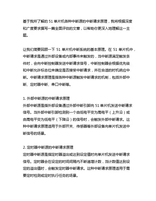
基于我所了解的51单片机各种中断源的中断请求原理,我将根据深度和广度要求撰写一篇全面评估的文章,以帮助你更深入地理解这一主题。
让我们简要回顾一下51单片机中断系统的基本原理。
在51单片机中,中断请求是通过外部设备或内部事件来触发的,当中断源满足触发条件时,会向中断控制器发送中断请求信号,中断控制器会根据优先级和中断允许标志位来确定是否接受中断请求,并在合适的时机响应中断。
中断请求原理是指各种中断源触发中断请求的机制,包括外部中断、定时器中断、串口中断等。
1. 外部中断源的中断请求原理外部中断源是指外部设备通过外部中断引脚向51单片机发送中断请求信号。
当外部中断引脚检测到一个由低电平变为高电平(上升沿)或由高电平变为低电平(下降沿)的信号时,会触发外部中断请求。
这种中断请求原理适用于外部开关、传感器等外部设备向单片机发送中断信号的场景。
2. 定时器中断源的中断请求原理定时器中断源是指定时器溢出或达到设定值时向单片机发送中断请求信号。
定时器会在设定的时间间隔内不断递增计数,当计数值达到设定的溢出值时,会触发定时器中断请求。
这种中断请求原理适用于需要定时检测或定时执行任务的场景。
3. 串口中断源的中断请求原理串口中断源是指串口接收到数据或发送完成时向单片机发送中断请求信号。
当串口接收到数据或发送完成时,会触发串口中断请求。
这种中断请求原理适用于串口通信中需要实时处理数据的场景。
51单片机各种中断源的中断请求原理涵盖了外部中断、定时器中断和串口中断等多种情况。
理解和掌握这些中断请求原理,对于合理地设计中断服务程序和提高系统的实时性具有重要意义。
在个人观点和理解方面,我认为深入理解各种中断源的中断请求原理,可以帮助我们更好地设计和优化单片机系统的中断服务程序,提高系统的实时性和稳定性。
合理地利用中断请求原理,可以更好地利用单片机资源,提高系统的响应速度和效率。
在实际应用中,我们需要根据具体的需求和硬件环境,灵活运用各种中断源的中断请求原理,确保系统的稳定性和可靠性。
KeilC51学习4按键外部中断主板介绍:P3^2~P^5为四个按键;P1^0~P1^7为8个LED灯#include "reg52.h"//此⽂件中定义了单⽚机的⼀些特殊功能寄存器typedef unsigned int uint; //对数据类型进⾏声明定义typedef unsigned char u8;sbit k1=P3^5; //定义P31⼝是k1sbit led=P1^0; //定义P10⼝是led/******************************************************************************** 函数名 : delay* 函数功能 : 晶振11.0592M延时函数*******************************************************************************/void delay(uint z){uint i,j;for(j=z;j>0;j--)for(i=112;i>0;i--);}/******************************************************************************** 函数名 : keypros* 函数功能 : 按键处理函数,判断按键K1是否按下*******************************************************************************/void keypros(){if(k1==0){delay(50);if(k1==0) //再次判断按键是否按下led=~led; //led状态取反}while(!k1); //检测按键是否松开}/******************************************************************************** 函数名 : main* 函数功能 : 主函数* 输⼊ : ⽆* 输出 : ⽆*******************************************************************************/void main(){while(1){keypros(); //按键处理函数}}按键取反灯亮或灭计数器(计数器0⽤P3^4按钮,计数器1⽤P3^5按钮,不懂)/*-----------------------------------------------名称:计数器0论坛:编写:shifang⽇期:2009.5修改:⽆内容:通过外部按键计数进⼊中断执⾏LED取反------------------------------------------------*/#include<reg52.h> //包含头⽂件,⼀般情况不需要改动,头⽂件包含特殊功能寄存器的定义sbit LED=P1^0; //定义LED端⼝/*------------------------------------------------定时器初始化⼦程序(按钮P3^4控制,不知为什么)------------------------------------------------*/void Init_Timer0(void){TMOD |= 0x01 | 0x04; //使⽤模式1,16位计数器,使⽤"|"符号可以在使⽤多个定时器时不受影响TH0=0xFF; //给定初值TL0=245; //从245计数到255EA=1; //总中断打开ET0=1; //定时器中断打开}/*------------------------------------------------主程序------------------------------------------------*/main(){Init_Timer0();while(1);}/*------------------------------------------------定时器中断⼦程序------------------------------------------------*/void Timer0_isr(void) interrupt 1using1{TH0=0xFF; //重新给定初值TL0=245;LED=~LED; //指⽰灯反相,可以看到闪烁}计数器0/*-----------------------------------------------名称:计数器1论坛:编写:shifang⽇期:2009.5修改:⽆内容:通过外部按键计数进⼊中断执⾏LED取反------------------------------------------------*/#include<reg52.h> //包含头⽂件,⼀般情况不需要改动,头⽂件包含特殊功能寄存器的定义sbit LED=P1^0; //定义LED端⼝/*------------------------------------------------定时器初始化⼦程序------------------------------------------------*/void Init_Timer1(void){TMOD |= 0x10 | 0x40; //使⽤模式1,16位计数器,使⽤"|"符号可以在使⽤多个定时器时不受影响TH1=0xFF; //给定初值TL1=245; //从245计数到255EA=1; //总中断打开ET1=1; //定时器中断打开TR1=1; //定时器开关打开}/*------------------------------------------------主程序------------------------------------------------*/main(){Init_Timer1();while(1);}/*------------------------------------------------定时器中断⼦程序------------------------------------------------*/void Timer1_isr(void) interrupt 3{TH1=0xFF; //重新给定初值TL1=245;LED=~LED; //指⽰灯反相,可以看到闪烁}计数器1中断定义:当机器正在执⾏程序的过程中,⼀旦遇到⼀些异常或者特殊请求时,停⽌正在执⾏的程序转⼊必要的处理,处理完毕后,⽴即返回断点继续执⾏。
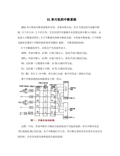
51单片机的中断系统8031单片机的中断系统简单实用,其基本特点是:有5个固定的可屏蔽中断源,3个在片内,2个在片外,它们在程序存储器中各有固定的中断入口地址,由此进入中断服务程序;5个中断源有两级中断优先级,可形成中断嵌套;2个特殊功能寄存器用于中断控制和条件设置的编程。
中断系统的结构:5个中断源的符号、名称及产生的条件如下。
INT0:外部中断0,由P3.2端口线引入,低电平或下跳沿引起。
INT1:外部中断1,由P3.3端口线引入,低电平或下跳沿引起。
T0:定时器/计数器0中断,由T0计满回零引起。
T1:定时器/计数器l中断,由T1计满回零引起。
TI/RI:串行I/O中断,串行端口完成一帧字符发送/接收后引起。
整个中断系统的结构框图见下图一所示。
由图一可见,外部中断有下跳沿引起和低电平引起的选择;串行中断有发送(TI)相接收(R1)的区别;各个中断源打开与否,受中断自身的允许位和全局允许位的控制,并具有高优先级和低优先级的选择。
中断系统的控制寄存器:中断系统有两个控制寄存器IE和IP,它们分别用来设定各个中断源的打开/关闭和中断优先级。
此外,在TCON中另有4位用于选择引起外部中断的条件并作为标志位。
IE在特殊功能寄存器中,字节地址为A8H,位地址(由低位到高位)分别是A8H-AFH。
IE用来打开或关断各中断源的中断请求,基本格式如下图二所示:EA:全局中断允许位。
EA=0,关闭全部中断;EA=1,打开全局中断控制,在此条件下,由各个中断控制位确定相应中断的打开或关闭。
×:无效位。
ES:串行I/O中断允许位。
ES=1,打开串行I/O中断;ES=0,关闭串行I /O中断。
ETl;定时器/计数器1中断允许位。
ETl=1,打开T1中断;ETl=O,关闭T1中断。
EXl:外部中断l中断允许位。
EXl=1,打开INT1;EXl=0,关闭INT1。
ET0:定时器/计数器0中断允许位。
ET0=1,打开T0中断;ET0=0,关闭TO中断。
51单片机中断优先级基本原则中断是指在程序执行的过程中,由硬件或软件触发,跳转至另一个函数或子程序中执行一段代码,然后再返回原来的程序执行点。
中断可以提高系统的响应速度和效率,并且可以优先处理紧急事件。
在51单片机的编程中,正确设置中断优先级是一项重要的任务,本文将介绍51单片机中断优先级的基本原则。
1. 中断的分类51单片机中的中断主要分为外部中断和定时器中断两种。
外部中断是通过外部引脚触发的,例如按键、传感器等外部事件。
而定时器中断是由定时器计算得出的,用于定时触发一些任务。
2. 中断优先级的概念在51单片机中,有多个中断源时,中断优先级决定了哪个中断先被执行。
较高优先级的中断会打断正在执行的较低优先级中断,这样可以保证紧急任务的及时处理。
3. 默认的中断优先级在51单片机中,默认情况下,各个中断的优先级是相同的。
如果不进行设置,那么多个中断发生时会按照它们的优先级设置顺序进行处理。
4. 中断优先级的设置方法在51单片机的编程中,可以通过设置中断优先级来控制各个中断的执行顺序。
下面是一种设置中断优先级的方法:a. 在程序中开启中断:通过设置中断打开寄存器(IE)的对应位来开启相应的中断源。
b. 设置中断优先级:通过设置中断控制寄存器(IP)的对应位来设置中断的优先级。
IP寄存器的每一位对应一种中断源,可以根据需要设置为高优先级或低优先级。
5. 中断优先级的基本原则在设置中断优先级时,需要遵守一些基本的原则:a. 优先处理时间敏感的中断:对于需要立即响应的事件,例如紧急报警、高优先级的通信等,应该将其设置为较高的中断优先级。
这样可以保证紧急任务的及时处理。
b. 避免高优先级中断长时间持续运行:较高优先级的中断可能会一直打断低优先级的中断,导致低优先级的任务得不到处理。
因此,需要合理设置中断优先级,避免高优先级中断长时间占用CPU资源。
c. 合理规划定时器中断和外部中断的优先级:定时器中断一般用于周期性任务,例如控制任务的周期性执行。
单片机查询工作方式和中断工作方式有什么不同,编程时有什么区别
单片机在操作外部设备时,常用的有中断和查询两种方式。
1、工作方式不同;
查询方式:发送数据——先发后查;
接收数据——先查后收。
中断方式:发送数据——发送、等待中断、中断中发送;
接收数据——等待中断、在中断中接收
中断方式,是事件触发的,换言之只要有事件产生都会进入中断,并且取得最优运行,因此响应更快,及时。
查询方式,就是在主函数里面不停循环,查询端口状态,响应速度慢。
2、编程时的区别;中断程序在程序开始定义中断入口地址,初始化中必须打开中断允许位,程序运行时不用判断溢出状态位,溢出后硬件清零;查询方式在程序运行时必须判断溢出状态位,溢出后须软件清零。
扩展资料:
单片机工作原理
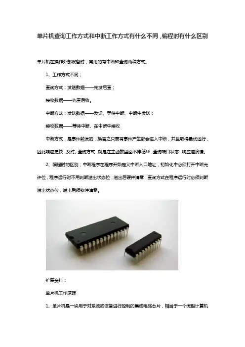
1、单片机是一块用于对系统或设备进行控制的集成电路芯片,相当于一个微型计算机
系统。
包含具有数据处理能力的中央处理器CPU、静态随机处理器SRAM、闪存FLASH、多种IO口和中断系统、定时器/计数器等功能。
2、可以把单片机看成是一台微型机器,程序员给它输入命令,它就执行相应的操作。
其过程大概如下:在一般的用户模式下,单片机先从FLASH中读取指令,译码电路识别该指令是哪个指令,并输出对应的控制信号给单片机内的各部件,各部件收到控制信号后执行相应的操作。
单片机串口通信在嵌入式系统中具有非常重要的作用,而其中串口中断的编写方式更是至关重要。
今天我们来讨论一下51单片机串口中断的两种写法。
1. 外部中断写法在51单片机中,串口通信一般使用串口中断来实现。
外部中断写法是一种常见的串口中断编写方式。
其具体步骤如下:1)需要设置串口工作参数,包括波特率、数据位、停止位和校验位等。
2)在主程序中使能串口中断,并设置中断优先级。
3)在中断服务函数中进行接收数据的处理,可以通过接收缓冲区、中断标志位等来判断接收数据的情况,并进行相应的处理。
2. 定时器中断写法除了外部中断写法,定时器中断也是一种常见的串口中断编写方式。
其具体步骤如下:1)同样需要设置串口工作参数,包括波特率、数据位、停止位和校验位等。
2)在主程序中初始化定时器,并使能定时器中断。
3)在定时器中断服务函数中进行接收数据的处理,同样可以通过接收缓冲区、中断标志位等来判断接收数据的情况,并进行相应的处理。
总结无论是外部中断写法还是定时器中断写法,都是实现51单片机串口通信的常见方式。
在选择具体的编写方式时,需要根据具体的应用场景和需求来进行选择。
在实际应用中,可以根据具体情况来灵活选择合适的串口中断编写方式,以便更好地满足系统的需求。
在实际编写中断服务函数时,需要注意以下几点:1)处理数据时需要考虑数据的完整性和准确性,可以通过校验位等手段来验证数据的正确性。
2)在中断服务函数中应尽量减少对全局变量的访问,以避免出现数据冲突和竞争的情况。
3)合理设置中断优先级,避免产生中断嵌套和冲突。
通过合理的中断编写方式和注意事项,可以更好地实现串口通信功能,提高系统的稳定性和可靠性,为嵌入式系统的应用提供良好的技术支持。
对于外部中断写法和定时器中断写法,两者各有优缺点。
外部中断写法在串口数据到达时能够即刻响应中断、处理数据。
但是,如果数据传输速率较快或需要高精度的数据处理,外部中断写法可能无法满足要求。
在这种情况下,定时器中断写法显得更加合适。
51单片机中断代码解释一、引言51单片机是一种广泛使用的微控制器,具有丰富的中断功能。
中断是单片机在执行程序过程中,由于某种原因需要暂停当前的任务,转而处理更为紧急的事件。
处理完该事件后,再返回到之前被中断的程序继续执行。
本文将对51单片机的中断代码进行详细解释,包括中断概念、中断源、中断寄存器和寄存器功能与赋值说明等方面。
二、中断概念中断是一种计算机系统中处理优先级更高任务的方式。
当某个事件发生时,CPU会暂时停止当前任务的执行,转而处理该事件。
处理完该事件后,CPU会返回到之前被中断的程序继续执行。
三、中断源51单片机有多种中断源,包括外部中断0、外部中断1、定时器0、定时器1等。
每个中断源都可以独立地开启或关闭,并且可以设置优先级。
四、中断寄存器51单片机与中断相关的寄存器主要有:1.ICON(中断允许控制寄存器):用于控制中断的开启和关闭。
可以通过设置ICON寄存器的相关位来启用或禁用某个中断。
2.INT0/INT1(外部中断0/1控制寄存器):用于控制外部中断0和外部中断1的触发方式、触发边沿和触发方式等。
3.TMOD(定时器模式控制寄存器):用于设置定时器的模式和工作方式。
4.TH0/TH1(定时器0/1计数器高8位寄存器):用于存储定时器的计数值。
5.TL0/TL1(定时器0/1计数器低8位寄存器):用于存储定时器的计数值。
五、寄存器功能与赋值说明1.ICON寄存器:o EA:全局中断允许位,设置为1时允许所有中断,设置为0时禁止所有中断。
o ET0:定时器0中断允许位,设置为1时允许定时器0中断,设置为0时禁止定时器0中断。
o ET1:定时器1中断允许位,设置为1时允许定时器1中断,设置为0时禁止定时器1中断。
o EX0:外部中断0允许位,设置为1时允许外部中断0,设置为0时禁止外部中断0。
o EX1:外部中断1允许位,设置为1时允许外部中断1,设置为0时禁止外部中断1。
2.INT0/INT1寄存器:o IT0/IT1:外部中断0/1触发方式选择位,设置为0时选择下降沿触发,设置为1时选择低电平触发。
一、中断的概念CPU在处理某一事件A时,发生了另一事件B请求C PU迅速去处理(中断发生);CPU暂时中断当前的工作,转去处理事件B(中断响应和中断服务);待C PU将事件B处理完毕后,再回到原来事件A被中断的地方继续处理事件A(中断返回),这一过程称为中断二、中断源在51单片机中有5个中断源中断号优先级中断源中断入口地址0 1(最高)外部中断0 0003H1 2 定时器0 000BH2 3 外部中断1 0013H3 4 定时器1 0018H4 5 串口总段0023H三、中断寄存器单片机有10个寄存器主要与中断程序的书写控制有关1.中断允许控制寄存器IE2.定时器控制寄存器TC ON3.串口控制寄存器SCON4.中断优先控制寄存器IP5.定时器工作方式控制寄存器TMOD6.定时器初值赋予寄存器(TH0/TH1,TL0/TL1)四、寄存器功能与赋值说明注:在用到中断时,必须要开总中断EA,即EA=1。
//开总中断1.中断允许控制寄存器IEEX0(EX1):外部中断允许控制位EX0=1 外部中断0开关闭合//开外部0中断EX0=0 外部中断0开关断开ET0(ET1):定时中断允许控制位ET0=1 定时器中断0开关闭合//开内部中断0ET0=0 定时器中断0开关断开ES: 串口中断允许控制位ES=1 串口中断开关闭合//开串口中断ES=0 串口中断开关断开2.定时器控制寄存器TCON //控制外部中断和定时器中断外部中断:IE0(IE1):外部中断请求标志位当INT0(INT1)引脚出现有效的请求信号,此位由单片机自动置1,cpu开始响应,处理终端,而当入中断程序后由单片机自动置0.//外部中断,即外部中断相应的引脚接入低电平或下降沿信号时,中断开始响应。
IT0(IT1):外部中断触发方式控制位//选择有效信号IT0(IT1)=1:脉冲触发方式,下降沿有效。
IT0(IT1)=0:电平触发方式,低电平有效。
实验一51单片机并行输入/输出实验——查询和中断方式
班级:车辆151 学号:姓名:
一、实验目的:掌握51单片机并行口输入/输出功能,并对比查询和中断方式编程方法。
二、实验内容:采用51单片机并行口P0~P3,通过1路或2路开关或按钮的状态,切换4个或8个LED的闪烁规律。
规律可以是循环点亮、全闪全灭、交替闪烁等。
并对比查询和中断方式对输入编程的区别。
实验题目:查询方式,P1.0~P1.3作为按钮输入,P0.0~P0.3作为输出到LED同步显示三、实验原理图:
四、实验源程序
五、流程框图
六、总结
程序设计思路是不断查询P1.0~P1.3的状态,从而决定P0.0~P0.3的电平高低,由于是准双向口,读入时应该写1再读。
使用查询方式时,CPU一直在查询输入信号的状态,从而决定输出信号,而使用中断方式时,则只需要等待事件触发,未触发时,CPU可以执行其它操作,效率高。
由于人眼的辨别能力有限,使用延时观察LED灯的状态时应该保证时间足够长。
浅谈51单片机2个外部中断的应用案例51单片机是一种常见的微控制器,具有丰富的外部中断功能。
在本文中,将浅谈51单片机中两个外部中断的应用案例,旨在帮助读者更好地理解和应用该功能。
外部中断是指通过外部信号触发单片机的中断执行程序。
51单片机具有2个外部中断引脚,分别是INT0和INT1,它们可以用于各种不同的应用。
下面将介绍两个典型的外部中断的应用案例。
1.停车场车位计数器停车场车位计数器可以利用51单片机的外部中断功能来实现。
假设停车场有3个车位,当车辆入场时,外部中断INT0触发,计数器加1;当车辆出场时,外部中断INT1触发,计数器减1、通过读取计数器的值,可以实时查看停车场内的剩余车位。
具体实现的步骤如下:1)初始化外部中断INT0和INT1,设置为下降沿触发。
2)将车位计数器初始化为0。
3)当接收到INT0中断信号时,车位计数器加14)当接收到INT1中断信号时,车位计数器减15)在主循环中,可以通过查询车位计数器的值来实时显示剩余车位数。
这个应用案例使得车辆管理变得更加智能化和便捷,方便停车场管理员实时了解停车位的使用情况。
2.控制智能家居设备智能家居设备的控制可以利用51单片机的外部中断功能来实现。
例如,当外部中断INT0触发时,可以控制家居设备的开关状态,比如打开或关闭灯光、电器等。
具体实现的步骤如下:1)初始化外部中断INT0,设置为下降沿触发。
2)在INT0中断服务程序中,判断当前设备的开关状态。
如果是关闭状态,则打开设备;如果是打开状态,则关闭设备。
3)在主循环中,可以通过查询当前设备的开关状态来实时显示设备状态。
这个应用案例使得智能家居设备的控制更加智能化和灵活,用户可以通过触发外部中断来实现对设备的远程控制。
总结:以上是两个常见的51单片机外部中断的应用案例。
通过合理应用外部中断功能,能够实现更多智能化、便捷化的功能,提高系统的可靠性和实用性。
希望本文能够对读者有所帮助,并激发更多的创意和思考。
C51单片机教程——中断的应用
一、中断的概念
中断是一种与主程序中断的机制,是CPU在遇到一个特定的事件触发后,立即从主程序中断,跳转到特定的中断服务程序(ISR)中执行。
一
旦中断程序执行完毕,CPU就会回到主程序的执行位置,继续执行主程序。
由于中断会立即响应,它可以用来处理急躁的外部设备事件,把实时性要
求比较高的任务处理正确,这些即使cpu在时间短暂中断,也不会对后续
程序运行产生太大的影响。
二、单片机中断的实现
1、中断类型:单片机的中断有外部中断与定时器中断两种,一般外
部中断处理外设的发出中断请求(如串口发出的数据中断、按键的按下中断),定时器中断用于定时计数(用于产生节拍用,如定时器中断每
10ms产生一个节拍)。
2、中断使能:单片机的中断有相应的中断使能位,当开启相应的中
断使能位时,单片机才会接受这种中断信号。
3、中断服务程序:单片机的中断服务一般由中断服务程序(ISR)实现,当CPU遇到中断时,会跳转到中断服务程序中,具体的由定义的中断
服务程序完成中断处理。
4、中断响应速度:中断响应速度是指单片机接收到中断信号到跳转
到中断服务程序的延时时间,这个速度受单片机芯片结构及设计的影响,
一般1-2微秒可以完成中断响应。