DISCO NBC-ZH刀片总结
- 格式:doc
- 大小:287.00 KB
- 文档页数:3
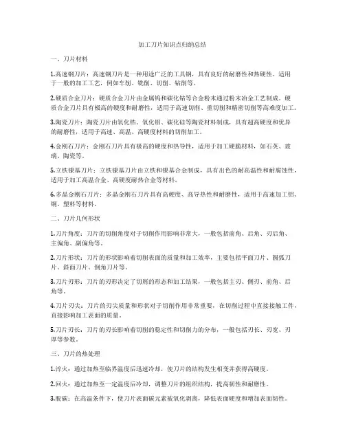
刀片总结1.刀片的介绍:1.1切割刀片的材料;1.1.1结合剂1.1.2钻石颗粒1.1.3铝架1.2刀片的直径:刀片的直径为2、3、4inch三种,目前切割所使用的为2inch的刀片;2.刀片的构造:2.1钻石颗粒:可分为金刚砂和CBN两种,2.2结合剂:可分为树脂型、金属型和金属电镀型,不同的结合剂应用于不同的加工材质,结合剂的作用是将钻石颗粒组合在一起;2.3刀片集中度:是指钻石颗粒在刀片中所占的比例;2.4刀片露出量和刀片宽度:A(刀片宽度),B(刀片露出量);3.刀片的切割原理:3.1撞击:当工作物属于硬脆的材质,钻石颗粒会以撞击的方式将工作物敲碎,再将将粉末移除;3.2挖除:当工作物属于软的材质,刀片会利用刀口将工作物一点一点地挖除并将粉末移除;3.3自我再生能力:自我再生能力的目的就是为了维持刀片的锋利狀态3.3.1断裂:钻石颗粒在长期的撞击之下,某些钻石颗粒会破裂,并在断裂面形成一些锐角,使刀片能夠继续维持在锋利的狀态。
3.3.2磨耗:切割时,因为摩擦的关系抓住钻石颗粒的结合剂会越來越少,当结合剂少到某一程度,同时在作用力的驱使下,钻石颗粒会自然脱落,而另一颗钻石也会自然显露出來。
4.刀片的型号:目前我司使用的刀片主要有两种,NBC-ZH系列和ZH05系列,两种刀片的参数如下;4.1DISCO NBC-ZH系列刀片技术规格说明:4.1.1特点:4.1.1.1可进行高难度的斜角切割和阶梯切割等切割加工;4.1.1.2多尺寸磨粒与各种结合剂的有机结合,能够满足用户不同的加工需求;4.1.1.3使超薄型切割刀片的装卸使用更方便;4.1.1.4由于提高了操作便利性,可大幅度缩短刀片交换及设备维护所需要的时间;4.1.2加工对象:硅晶片、半导体化合物晶片(GaAs等)、氧化物晶片(LiTaO3等)、其他材料;4.1.3适用设备:4.1.3.1全自动切割机:6000系列、600系列4.1.3.2半自动切割机:3000系列、300系列、500系列4.2.1特点:4.2.1.1可进行高难度的斜角切割和阶梯切割等切割加工;4.2.1.2多尺寸磨粒与各种结合剂的有机结合,能够满足用户不同的加工需求;4.2.1.3使超薄型切割刀片的装卸使用更方便;4.2.1.4由于提高了操作便利性,可大幅度缩短刀片交换及设备维护所需要的时间;4.2.2加工对象:硅晶片、半导体化合物晶片(GaAs等)、氧化物晶片(LiTaO3等)、其他材料;4.2.3适用设备:4.2.3.1全自动切割机:6000系列、600系列4.2.3.2半自动切割机:3000系列、300系列、500系列4.2.4技术规格:。


加工刀片知识点归纳总结一、刀片材料1.高速钢刀片:高速钢刀片是一种用途广泛的工具钢,具有良好的耐磨性和热硬性。
适用于一般的加工工艺,例如车削、铣削、切削、钻削等。
2.硬质合金刀片:硬质合金刀片由金属钨和碳化钴等合金粉末通过粉末冶金工艺制成。
硬质合金刀片具有极高的硬度和耐磨性,适用于高速切削、重切削和精密切削等高难度加工。
3.陶瓷刀片:陶瓷刀片由氧化锆、氧化铝、碳化硅等陶瓷材料制成,具有超高硬度和优异的耐磨性,适用于高速、高温、高硬度材料的切削加工。
4.金刚石刀片:金刚石刀片具有极高的硬度和热导性,适用于加工硬脆材料,如石英、玻璃、陶瓷等。
5.立铁镍基刀片:立铁镍基刀片由立铁和镍基合金制成,具有出色的耐高温性和耐腐蚀性,适用于加工高温合金、高硬度耐热合金等材料。
6.多晶金刚石刀片:多晶金刚石刀片具有高硬度、高导热性和耐磨性,适用于高速加工铝、铜、塑料等材料。
二、刀片几何形状1.刀片角度:刀片的切削角度对于切削作用影响非常大,一般包括前角、后角、刃后角、主偏角、副偏角等。
2.刀片形状:刀片的形状影响着切削表面的质量和加工效率,主要包括平面刀片、圆弧刀片、斜面刀片、倒角刀片等。
3.刀片刃形:刀片的刃形决定了切屑的形态和加工结果,一般包括主刃、侧刃、前角、后角等。
4.刀片刃尖:刀片的刃尖质量和形状对于切削作用非常重要,在切削过程中直接接触工件,直接影响加工表面的质量。
5.刀片刃长:刀片的刃长影响着切削的稳定性和切削力的分布,一般包括刃长、刃宽、刃厚等参数。
三、刀片的热处理1.淬火:通过加热至临界温度后迅速冷却,使刀片的结构发生相变并获得高硬度。
2.回火:通过加热至一定温度后冷却,调整刀片的组织结构,提高韧性和耐磨性。
3.脱碳:在高温条件下,使刀片表面碳元素被氧化剥离,降低表面硬度和增加表面韧性。
4.氮化:在刀片表面渗氮处理,提高刀片的硬度和耐磨性。
5.表面涂层:在刀片表面涂覆涂层,用于降低刀片摩擦、提高耐磨性和延长刀片使用寿命。

DISCO公司產品介紹一:自動切割機什麼是自動切割機?是指被加工物的安裝及卸載作業均採用手動方式進行,只有加工工序實施自動化操作的切割機。
在有些機型上也可實施自動化位置校準作業。
但在機器內部沒有配置清洗、乾燥裝置.位置校準切割操作人員以手動方式將被加工物安裝到工作盤上。
3000系列的設備可自動實施位置校準作業。
300系列和500系列的設備,由操作人員使用顯微鏡進行切割位置對準作業。
操作人員只要按下開始按鈕,機台就可在位置校準工序識別出的切割道進行切割加工。
300系列 - Automatic Dicing Saw300系列切割機/切斷機,利用人工方式完成加工物的安裝調整及識別切割位置的校準作業,並且在設計上力求節省佔地空間,使該機型的外形結構顯得簡潔精巧。
另外,為了滿足各種加工要求,在最大加工物尺寸和加工精度等方面,均擁有種類豐富的產品群。
For 6" frameDAD321DAD322DAC351/DAD361設備概要適用ø 6"加工物的自動切割機DAD321的改良機型,産能更高追求高精度的切斷機和自動切割機最大加工物尺寸160 x 160ø6"(邊長6"方形)*1DAC351: 153 x 153 DAD361: 160 x 160適用框架2-6-1DAC351: - DAD361: 2-5, 2-6X軸可切割範圍(mm)192160192進刀速度有效範圍(mm/s)0.1 - 3000.1 - 5000.1 - 300Y軸可切割範圍(mm)162最小步進量(mm)0.00020.0001定位精度(mm)0.005以內/160(單一誤差)0.003以內/50.001以內/160(單一誤差)0.001以內/5光學尺最小分辨率(mm)-0.00005Z軸有效行程(mm)28.2(ø 2"切割刀片)32.2(ø 2"切割刀片)28.2(ø 2"切割刀片)最小移動量(mm)0.00010.000050.0001重復定位精度(mm)0.0010.0005可使用的最大切割刀片直徑(mm)ø76.2ø58(使用1.5 kW的主軸時)ø76.2θ軸最大旋轉角度(deg)380320DAC351: -DAD361: 380主軸額定功率(kW)1.5 at 30,000 min-1額定力矩(N・m)0.48轉速範圍(min-1)3,000 - 40,000設備尺寸(WxDxH)(mm)500 x 1,050 x 1,455500 x 900 x 1,600500 x 1,050 x 1,455設備重量(kg)約500約420(無變壓器)約470(有變壓器)約550*1另外需要專用夾具。
专业:机械制造及其自动化班级:机制(3)班姓名:XXX时间:2014/7/3目录摘要…………………………………………1. 关键字………………………………………2. 前言…………………………………………3.1 硬质合金的概述1.1 硬质合金1.2 市场概况2 硬质合金的生产工艺2.1 生产原料2.2工艺流程2.3 加工种类2.4 加工种类优缺点对比3 硬质合金性能及其与使用关系3.1 硬度3.2 抗弯刚度3.3 冲击韧性3.4 耐磨性3.5 抗压强度3.6 导热率3.7 线胀系数4 硬质合金的种类及其用途4.1 硬质合金的种类4.2 各种牌号硬质合金的用途5 硬质合金的加工设备5.1 球磨机5.2 制粒设备5.3 自动压机5.4 单体真空脱蜡烧结炉6 国外硬质合金6.1 瑞典6.2 美国6.3 日本6.4 以色列小结…………………………………………... 参考资料……………………………………... 致谢…………………………………………...摘要:硬质合金石由难熔金属的碳化物以铁族金属钴或镍作胶结金属,用粉末冶金方法制造的合金材料。
由于硬质合金具有高硬度、耐磨损、耐腐蚀、耐高温和线胀系数小一系列优点,在现代工业生产中,已成为金属加工、矿山开采、石油钻探,国防军工等不可缺少的重要工具材料。
关键字:硬质合金性能工艺设备前言硬质合金具有很高的硬度、强度、耐磨性和耐腐蚀性,被誉为“工业牙齿”,并且未来高新技术武器装备制造、尖端科学技术的进步以及核能源的快速发展,将大力提高对高技术含量和高质量稳定性的硬质合金产品的需求。
随着国民经济的迅速增长,硬质合金的需求也高速增长。
因此研究并了解硬质合金是十分有意义的事情。
1 硬质合金的概述1.1 硬质合金由难熔金属的硬质化合物和粘结金属通过粉末冶金工艺制成的一种合金材料。
硬质合金具有硬度高、耐磨、强度和韧性较好、耐热、耐腐蚀等一系列优良性能,特别是它的高硬度和耐磨性,即使在500℃的温度下也基本保持不变,在1000℃时仍有很高的硬度。

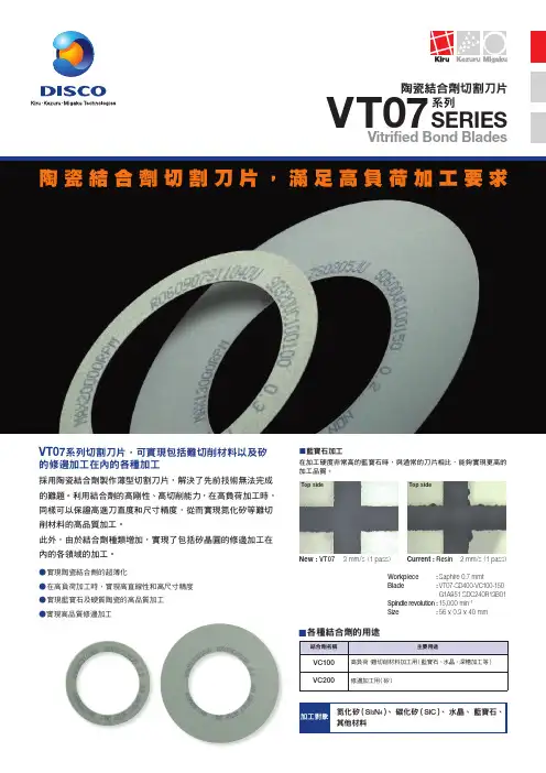
NBC-ZH 系列擁有優越的研削性能及較長的使用壽命,可有效提高生產效率及加工品質迪思科公司以其獨特的技術開發出了輪轂型切割刀片「NBC-ZH 」系列。
通過採用高性能超薄金剛石(鑽石)刃與鋁合金法蘭盤的一體化結構,不但提高了加工效率而且獲得了穩定的加工品質。
並借助迪思科公司豐富的應用加工技術,在切割加工硅(矽)晶圓及以GaAs 為代表的化合物半導體晶圓時,能夠獲得優越的加工品質。
● 可進行高難度的倒角切割和階梯切割加工●多尺寸磨粒與各種結合劑的有機結合,可滿足用另不同的加工需求● 使超薄型切割刀片的裝卸作業更方便●由於提高了操作便利性,可大幅度縮短切割刀片交換及設備維護所需要的時間●環保型的PP (聚丙稀)包裝NBC -ZH Electroformed Bond Blades with HUBSERIES向最高加工品質挑戰的高性能輪轂型切割刀片通知本公司,另外在初次訂購時,本公司銷售窗口會根據不同加工要求,協助用戶選擇最適合的產品,屆時請一併提供研削材料、尺寸、形狀、所用設備(裝置)及其他相關加工條件等資料。
為了改進產品,本公司可能在未通知用戶的情況下,就對產品規格進行變更,因此請仔細核對規格後再下訂單。
本公司的所有產品都已加入產品賠償責任保險。
2-13-11 143-8580Phone:81-3-4590-1000 Fax:81-3-4590-1001 www.disco.co.jp● 請使用安全擋板(包括噴嘴外殼或外蓋)。
● 在使用注有限制旋轉數的精密加工治具時,請不要超出其規定的旋轉數範圍。
● 在安裝精密加工治具時,請遵照設備(裝置)使用說明書的規定,正確地進行安裝。
● 請不要使精密加工治具掉落在地上,或發生碰撞。
● 在每次使用精密加工治具前必須先進行檢查,如果有缺口或其他破損,請停止使用。
● 在開始使用前,請先仔細閱讀相關設備(裝置)的使用說明書。
● 請不要使用經過改裝的設備(裝置)。

刀片总结1•刀片的介绍:1.1切割刀片的材料;1.1.1结合剂1.1.2钻石颗粒1.1.3铝架1.2刀片的直径:刀片的直径为2、3、4inch三种,目前切割所使用的为2inch的刀片;2.刀片的构造:2.1钻石颗粒:可分为金刚砂和CBN两种,2.2结合剂:可分为树脂型、金属型和金属电镀型,不同的结合剂应用于不同的加工材质,结合剂的作用是将钻石颗粒组合在一起;2.3刀片集中度:是指钻石颗粒在刀片中所占的比例;2.4刀片露出量和刀片宽度:A(刀片宽度),B(刀片露出量);ilub SideaJ~ \A - Blade Thkkness \B = Blade Expusure \Top Side3.刀片的切割原理:3.1撞击:当工作物属于硬脆的材质,钻石颗粒会以撞击的方式将工作物敲碎,再将将粉末移除;3.2挖除:当工作物属于软的材质,刀片会利用刀口将工作物一点一点地挖除并将粉末移除;3.3自我再生能力:自我再生能力的目的就是为了维持刀片的锋利狀态3.3.1断裂:钻石颗粒在长期的撞击之下,某些钻石颗粒会破裂,并在断裂面形成一些锐角,使刀片能夠继续维持在锋利的狀态。
3.3.2磨耗:切割时,因为摩擦的关系抓住钻石颗粒的结合剂会越來越少,当结合剂少到某一程度,同时在作用力的驱使下,钻石颗粒会自然脱落,而另一颗钻石也会自然显露出來。
4.刀片的型号:目前我司使用的刀片主要有两种,NBC-ZH系列和ZH05系列,两种刀片的参数如下;4.1 DISCO NBC-ZH系列刀片技术规格说明:4.1.1特点:4.1.1.1可进行高难度的斜角切割和阶梯切割等切割加工;4.1.1.2多尺寸磨粒与各种结合剂的有机结合,能够满足用户不同的加工需求;4.1.1.3使超薄型切割刀片的装卸使用更方便;4.1.1.4由于提高了操作便利性,可大幅度缩短刀片交换及设备维护所需要的时间;4.1.2加工对象:硅晶片、半导体化合物晶片(GaAs等)、氧化物晶片(LiTaO3 等)、其他材料;4.1.3适用设备:4.1.3.1全自动切割机:6000系列、600系列4.1.3.2半自动切割机:3000系列、300系列、500系列4.1.4技术规格4.2 DISCO ZH05系列刀片技术规格说明:4.2.1特点:421.1可进行高难度的斜角切割和阶梯切割等切割加工;4.2.1.2多尺寸磨粒与各种结合剂的有机结合,能够满足用户不同的加工需求;4.2.1.3使超薄型切割刀片的装卸使用更方便;4.2.1.4由于提高了操作便利性,可大幅度缩短刀片交换及设备维护所需要的时间;4.2.2加工对象:硅晶片、半导体化合物晶片(GaAs等)、氧化物晶片(LiTaO3 等)、其他材料;4.2.3适用设备:4.2.3.1全自动切割机:6000系列、600系列4.2.3.2半自动切割机:3000系列、300系列、500系列4.2.4技术规格:【下载本文档,可以自由复制内容或自由编辑修改内容,更多精彩文章,期待你的好评和关注,我将一如既往为您服务】。
划片机作业手册-----DiscoAutoma tic Dicing Saw 9890501 发表于: 2005-11-26 22:17 来源: 半导体技术天地(disco)1.0 TitleDiscoAutoma tic Dicing Saw2.0 Purpos eThe DiscoAutoma tic Dicing Saw is a precis ion machin e used to cut semico nduct or wafers into indivi dualchipsor dice. Wafers are held to the chucktableby meansof vacuum and t he chuckcan accomm odate wafers with diamet ers from 2" to 6 ". The maximu m tablestroke (left-rightmoveme nt of the chu cktable) is 160 mm (6 5/16"). The cuttin g rangeis 20.4 mm to 153 mm in 1 mm increm ents(0.8" to 6" in 0.025" increm e nts). The cuttin g feed speedis variab le from 0.3 to 10 mm/ sec. (0.012" to 12"/sec).The dicing wheelis mounte d on a high freque ncy air-bearin gspindl e with an averag e rotati on speedof 30,000 rpm. The rangeof depthleft uncutis variab le, and ranges from 0.00 5 mm to 19.995 mm (0.0002" to 0.7872") in stepsof 0.005 mm (0.0002") increm ents. (Do not use a Z-indexof less than 0.07 mm withou t consul tinga superu ser.)Follow ing each cut, the Discouses stored parame tersto aut oma tical ly indexthe waferalongthe Y-axis. The maximu m sp indl e stroke (forwar d-backwa rd moveme nt of spindl e) is 160 mm (6 5/16"), and the variab le spindl e indexranges from 0. 002 mm to 99.998 mm (0.0001" to 4") in indexi ng stepsof 0. 002 mm (0.0001") increm ents.3.0 ScopeThereare four fixedsawing modesavaila ble:MODE AThe cut is made only in one direct ion as the chuckmovesfr om rightto left (down cut).MODE BThe cut is made in both direct ionsalongthe X-axis (down c ut/up cut).MODE CThis mode also cuts in both direct ionsalongthe X-axis, bu t the bladedescen ds within the rangeof 0.005-19.995 mm al ongthe Z-axis when the chucktablemovesfrom left to righ t. Use this mode for cuts deeper than 650 micron s.MODE DThis mode is constr ucted with a DRESS, whichuses a dressb oard, and a PRE-CUT, whichuses a dummywafer.Dicing tape and hoopsare availa ble in the Microl ab. Tape c an be foundon a dispen ser in 432b, and hoopsare stored be neat h the discosaw. Dicing tape is recomm ended for all dic ing operat ionsand is requir ed for throug h wafercuts.4.0 Applic ableDocume nts5.0 Defini tions and Proces s Termin ology6.0 Safety7.0 Statis tical/Proces s Data8.0 Availa ble Proces s, Gases, Proces s Notes8.1 Cuttin g Blades In UseSilico n BladeSemite c Corp. PN S2525kerf (widthof cut) = .64 micron s or .0025”Maximu m depthof cut = 640 micron s or .025”Cerami cs, saphir e, crysta l substr ateDicing Techno logy, PN CX-004-270-040-Hkerf .004”, 50-70 micron abrasi ve, 1 mm or .040” exposu reRecomm ended cuttin g speed, best cut: ..25 mm/sec, Z-index: . 7, .04Maximu m cuttin g speed: .5 mm/sec (more chippi ng)GlassDicing Techno logy, PN CX-010-600-060 Jkerf .010”, 22-36 micron abrasi ve, 1.5 mm or .060” exposu reRecomm ended cuttin g speed, best cut: .5 mm/sec, Z-index: .7, .04Maximu m cuttin g speed: 1 mm/sec9.0 Equipm ent Operat ion9.1 Operat ing Precau tionsSilico n partic les (shippe d pieces) produc ed by dicing operation will coat your sample s, if you do not use a protec tive layer. Theseare sharpedgedpartic les, whichcan easily p enetr ate the underl yingstruct ure, and are very diffic ult o r imposs ibleto remove. It is highly recomm ended that you c oat your wafers with 1-2 microm eters of photor esist as a sa crif icial layerthat can trap and laterremove partic les (p ost dicing operat ion). You can use the manual spinne r (head wa y) or the automa ted tracksystem s (SVG) to perfor m this c oatin g.Chapte r 1.3 of the manual, module 6 (MOD6) provid es and ove rvi ew of the resist coatin g proced ure, if you are not familiar with this proces s. Please note that thereis no need fo r HMDS treatm ent of wafers surfac e (skip Sectio n A). Once w aferis dicedyou can easily remove your resist layeralong with the partic les in a aceton e bath follow ed by isopro pan ol and a DI rinse/dry steps(soak sample s for 2 minute s in aceton e, DI rinse, then 2 minute s in isopro panol follow ed by DI rinse).Before operat ing the saw, be sure to verify the follow ing:9.1.1 The bladeis intact. If you attemp t to cut a w aferwith a damage d blade, it may causesevere damage to th e spindl e. You may change the bladeby follow ing the proced ure posted on the wall. Be carefu l not to applyexcess ive f orceto the spindl e. Use the torque driver that is kept by the saw.9.1.2 The AUTOBR EAKER CONTRO L switch (locate d on the rightside of the main body) is turned on (in the UP position).9.1.3 The air is on and is beingsuppli ed at 80 psi (or more).9.1.4 The wateris on.9.1.5 The STANDB Y lightis on.During operat ion, make sure:9.1.6 Your waferis no more than 550 um thick. If yo u are cuttin g thickwafers, waferstacks, etc., you must us e MODE C. Otherw ise, the saw bladewill scrape alongyour w aferon the return stroke, damagi ng your wafer, the blade, and possib ly the spindl e. Simila rly, neverattemp t to make a cut that is deeper than the expose d amount of saw blade, sincethis will placea high load on the spindl e and possib ly damage it.Dicing blades are made of thin materi al and cannot be used for side grindi ng. If you are dicing a sample (a half wafe r, etc), whichhas a pre-existi ng flat edge parall el to the cuttin g direct ion, be very carefu l not to let the bladein dexover and try to cut rightalongthe edge of the sample. The latera l forces that are induce d in the bladewill easi ly peel it off the bladeholder.9.1.7 Coolin g wateris beingsuppli ed to the cuttin g area, at a flow rate of at least0.3 lpm.9.1.8 Always perfor m a Setupafterchangi ng the blad e. Otherw ise, if the new bladeis at all larger than the ol d blade, it may cut into the chuck.Note: Spindl e Shutdo wnThereare two ways to stop the spindl e from rotati ng. Pressing the button SPINDL E will turn off the spindl e and preser ve the height settin g. Pressi ng the EM STOP will stop the s pindl e, raiseit, return it to the home positi on and erasethe height inform ation.If a bladeis to be change d, it is impera tiveto use EM STO P rather than spindl e to stop rotati on so new height inform ation is progra mmedfollow ing the bladechange.NEVERTURN OFF THE DISCOWHILETHE SPINDL E IS TURNIN G.FIRSTSTOP THE SPINDL E ROTATI ON WITH ONE OF THE ABOVEMETHODS.9.2 Initia l Set-UpBefore beginn ing the actual operat ion, the saw must be "set -up". This allows the machin e to verify the zero refere nce pointalongthe Z-axis (i.e. verifi es the chuckheight). Th is proced ure is done withou t a waferon the chucktableas the presen ce of a wafermay causedamage to either the blad eor the wafer. Be sure that thereis no waterpresen t on t he surfac e of the chucktable. The proced ure is as follow s:9.2.1 Checkthat the spindl e coveris on tightl y. Pr essthe SPINDL E button (the LED should now be lit). Verify that the spindl e is rotati ng.9.2.2 Pressthe ILLUMI NATIO N button to turn on the l ights to the micros cope.9.2.3 Pressthe VACUUM button (the LED should now be lit).9.2.4 Pressthe SET UP button. This will causethe b ladeto rise alongthe Z-axis and stop at the limitof trav el alongthe Z-axis. The chucktablewill now move to and stop at approx imate ly the center of the Y-axis. The chuckta blewill then move alongthe X-axis from the left to the SE T UP positi on and stop. The bladewill descen d alongthe Z-axis and touchthe surfac e of the chucktable, then immedi a tely risesto form a gap equalto the amount entere d into t he Z INDEX. The chucktablewill now move alongthe X-axis to the positi on of the micros copeand stop. The SET UP lamp will now come on to indica te the comple tionof the SET UP operat ion.9.3 Progra mmingThereis spaceavaila ble for storin g 10 differ ent progra ms (Prog.#0-#9). Progra mmabl e parame tersinclud e:► MODE of cuttin g► CUT STRK: length of the cuttin g stroke► CUT SPD: speedof cut (see TableI for settin gs)► Y-IND: steppi ng indexin Y► Z-IND: distan ce to be left uncutas measur ed up from the chuckzero refere nce point► Theta-IND: anglethat the waferis rotate d betwee n c uts done for block1 and for block2The follow ing is a detail ed exampl e of the proced ure for en teri ng data:9.3.1 Pressthe INCH/MM button to select units. The INCH will lightto indica te all parame terswill be set in i nches, whilethe MM will lightto indica te the select ion of mm (for this exerci se choose mm).9.3.2 PressFIX, and the curren t cuttin g MODE will be displa yed.9.3.3 Pressthe MODE button untilthe desire d MODE i s displa yed (for this exerci se select A).9.3.4 Pressthe PROG# key and use the numeri c keypads to enterthe desire d progra m number (for this exampl e ent er1).9.3.5 Pressthe C (clear) key. This will eraseall c urren t parame tersentere d for the select ed progra m.9.3.6 The CUT STRK LED should now be blinki ng to ind ica te that this is the curren t parame ter for progra mming. T he firstdata that you enterwill be the valuefor the desi re d cuttin g patter n, whichis square. The cut stroke remain s the same length and is equalto the diamet er of the wafe r. Enteri ng a 0 will give the square patter n. This data is shownin the BLOCKdispla y.9.3.7 The CUT-STRK LED should stillbe blinki ng to i ndica te that it is the curren t parame ter for progra mming. T he CUT-STRK is usuall y equiva lentto the waferdiamet er, an d is the length of the desire d cut (the center of the chuck is used to determ ine wherethe cut begins; e.g. for a 100m mstroke the cut will begin50mm to one side of the center and contin ue 50mm beyond the center). Use the keypad to ent erthe desire d value(for this exampl e enter100 for 100 mm).9.3.8 Pressthe W key to write(enter) the data.9.3.9 The CUT-SPD LED should now be blinki ng to indi ca te that it is the curren t parame ter for progra mming. Chec kTableI for the valueto enterto get the desire d X-axis speed. Use the numeri c keypad s to enterthe desire d value. For this exerci se enter15. Note: Be carefu l when select ing a valueto enteras too greata speedwill breakthe blade!9.3.10 Pressthe W key to write(enter) the data.9.3.11 The Y-IND LED should now be blinki ng to indica te that it is the curren t parame ter to progra m. Use the numeric keypad s to enterthe desire d cuttin g index(in mm) for b lock1. Be sure to use the decima l pointif necess ary. For t his exampl e, enter10.880 (if you are unsure of the correc t valuefor the Y-INDEX, you can measur e this distan ce using the DATA SEL button as detail ed in Sectio n 9.6).9.3.12 Pressthe W key to write(enter) the data.9.3.13 Y-IND LED is stillblinki ng to indica te that it is waitin g to be progra mmed. Use the numeri c keypad s to ent erthe desire d cuttin g index(in mm) for block2. For this e xampl e, enter10.880. Note: block2 cuts will be the firsto nes made when usingthe FULL AUTO mode.9.3.14 Pressthe W key.9.3.15 The Z-IND LED should now be blinki ng to indica te that it is the curren t parame ter for progra mming. Use the numeri c keypad to enterthe desire d value. The valueentere d (in mm) is the depthleft UNCUTas measur ed up from the c huck. Dicing tape thickn ess of 125 micron s should be takeninto consid erati on. When usingdicing tape, throug h waterc uts can be achiev ed with a Z-indexno less than the minimu m recomm ended 0.07 mm. For this exerci se, enter0.15.9.3.16 Pressthe W key.9.3.17 The Theta-IND LED should now be blinki ng. Use the numeri c key to enterin the desire d valuefor the angle,whichthe chuckwill rotate, betwee n cuts made for block2 a nd block1. This valuewill almost always be 90, so enterth is value.9.3.18 Pressthe W key. Progra mming is comple ted.To view your progra m, pressthe SHIFTkey succes sivel y to d ispla y each parame ter. If a parame ter must be change d, firs tpressthe C/E key and then re-enterthe data. Be sure to pressthe W key to enterthe new data.9.4 Operat ing ModesThereare two differ ent modesof operat ion: (1) fullyautomatic (FULL AUTO), and (2) semi automa tic (SEMI AUTO). Both modesuse the curren tly select ed progra m for determ ining cu ttin g parame ters.9.4.1 FULL AUTOThe fullyautoma tic mode will cut both channe ls (afterwafe ralignm ent) as indica ted in the follow ing cuttin g sequen ce: Channe l 1 manual alignm ent -> Manual rotati on to Channe l 2 -> Channe l 2 manual alignm ent -> Channe l 2 automa tic cut tin g -> Automa tic rotati on to Channe l 1 -> Channe l 1 automa tic cuttin g. The FULL AUTO button must be on (LED will be l it) whilealigni ng, and cuttin g is initia ted with the START/STOP button. The bladecoolin g waterturns'on' at this po int. Adjust waterflow with the contro l knob on the rotame t er. You can tempor arily halt the cuttin g operat ion to inspect the cut by depres singthe START/STOP button. This turnscoolin g wateroff. Once the START/STOP button has been depr es sed, cuttin g will contin ue untilthe curren t cut is made all the way across the wafer, then the chuckwill move unde rthe micros copefor viewin g. Pressi ng the START/STOP button againwill reinit iatecuttin g and the chuckwill automa ti cal ly indexto the positi on for the next cut. Leavin g it st oppe d too long may causeit to halt comple telyand revert t o manual mode, so be carefu l to quickl y do any requir ed ins pec tions.9.4.2 SEMI AUTOSEMI AUTO mode allows you to aligneach cut before it is made, or you can use it to automa tical ly indexand cut the wa ferafteronly a single alignm ent is made. Note: SEMI AUTO will not automa tical ly rotate the wafer. In SEMI AUTO mode you beginby manual ly aligni ng the wafer, then you depres s the SEMI AUTO button (waterto the bladewill beginto spra yat this point). To initia te cuttin g, pressone of the Y m oveme nt arrows. Adjust waterflow with rotame ter contro l kn ob. Cuttin g will beginalongthe same path by whichyou ali gne d the wafer, and will then automa tical ly indexin the sa me direct ion as the Y moveme nt arrowyou used to initia te c uttin g. If you wish to halt the cuttin g proces s, depres s ei ther of the follow ing button s: SEMI AUTO, REPEAT, INDEX, or JOG/SCAN (for the Y axis). The bladewill contin ue the cut across the waferthen the chuckwill move underthe scopefor viewin g. The coolin g waterwill stop. You can then use the INDEXand Y arrowbutton s (whichwill move the chuckin the select ed Y direct ion the amount whichis stored for th e Y-IND in the curren t progra m) or JOG/SCAN to move the waf erto the next desire d positi on, alignthe waferand make a nothe r cut. This proces s can be repeat ed as many timesas d esire d.9.4.3 Alignthe micros copecrosshair to the blade.Note: The two knobsnear the micros copeon the discoare (1) focusand (2) front-back kerf widthadjust ment(if the cut is not beingmade wherethe micros copesays it should be). Lab techssugges t usersnevertouchthe kerf adjust men t. It's almost nevernecess ary to use the focuseither.9.5 WaferAlignm entAfterenteri ng your progra m and decidi ng on the type of ope rat ing mode to use, the next step is to prepar e your waferfor dicing.Dicing tape can be used with hoops(snap ring set) to better contro l the dicing proces s. A set of dicing hoops(an inn erhoop and an outerhoop) will hold the dicing tape tightl y over the hoops. First, placea square of dicing tape, adh esi ve side up on the innerloop. Second, forcethe outerho op over the innerhoop from the adhesi ve side of the dicing tape. The result should be a tightsurfac e of dicing tape readyto accept a wafer. Please do not take the dicing rings(hoops) away from the discostatio n. Snap ringsand dicing tape should be kept in 432C, the room adjace nt to the Dis costatio n.Now placeyour waferon the chuckand alignit precis ely:9.5.1 For FULL AUTO mode, depres s the FULL AUTO button (LED will light).9.5.2 With the VACUUM off, center your waferon the chuck.9.5.3 Depres s the VACUUM button to turn on vacuum (L ED will light) to the waferand checkthe vacuum gauge--it should be in the greenrangewith a waferon the chuck.9.5.4 Maneuv er the micros copeover the wafer(the sc opewill be positi onedover the center of the chuckautoma t ical ly if FULL AUTO is enable d when you turn on the VACUUM).9.5.5 Use the ThetaJOG/SCAN and arrowbutton s to al ignyour waferin theta. Be sure to pressthe arrowbutton,whichis outlin ed in greenlast, as this enters the positi on into the Disco's memory.9.5.6 Use the Y-Axis JOG/SCAN and arrowbutton s to p recis ely alignyour waferin Y. Be sure to pressthe arrowbutton, whichis outlin ed in greenlast, as this will enter the positi on into the Disco's memory. For SEMI AUTO, you a re now readyto begincuttin g by pressi ng the SEMI AUTO but ton (waterto the bladewill beginto spray), and the desired Y arrowbutton.9.5.7 For FULL AUTO mode, depres s ROTATI ON and one of the thetadirect ion arrows to rotate the waferin prepar a tion for block2 alignm ent. Repeat steps9.5.5 and 9.5.6 for precis e alignm ent. (Rememb er to pressthe arrowbutton, wh ichis outlin ed, in greenlast!) Pressthe START/STOP button to initia te automa tic cuttin g.9.6 Measur ing Distan ce Alongthe Y-AxisIf you are unsure of the precis e valueto enterfor the Y-I ND, the Discohas a featur e, whichallows you to measur e distan ces alongthe Y-Axis as detail ed in the follow ing:9.6.1 Usingthe Y and ThetaJOG/SCAN arrows, positi o n your waferat the desire d starti ng pointfor beginn ing me asur ement s.9.6.2 Pressthe DATA SEL button.9.6.3 Pressthe 1 button on the numeri c keyboa rd. The data panelwill now displa y zerosto indica te that this i s the zero starti ng point.9.6.4 Make sure that the Y JOG/SCAN is enable d (LED will be lit), and use the arrowbutton s to move the wafert o the desire d measur ement locati on.9.6.5 Data displa yed on the panelis the measur ed Y-Axis moveme nt in mm (or inches if this is the select ed unit option). A negati ve valueindica tes that moveme nt is toward the frontof the machin e, whilepositi ve indica tes moveme nt to the rear.9.6.6 Record this value(it will disapp ear when you disabl e this featur e) for use when progra mming Y-IND.9.6.7 Pressthe SHIFTbutton to disabl e the Y-Axis d istan ce measur ement featur e.9.7 Action s Danger ous to DiscoBe sure that you unders tandthe follow ing ways that the mac hin e can be damage d, and be carefu l not to make thesemistakes:9.7.1 The air-bearin g spindl e can be galled and ruin ed if it is rotate d by hand when the 80 psi air is not on. For exampl e, if you change the bladewithou t firstturnin g on the powerto the machin e (so air flowsto the spindl e), the bearin g surfac es will rub agains t each otherand be dam age d. So the firstthingyou must always do before touchi ng the spindl e is to turn on the power, and wait a few second s for the air pressu re to come up.r than t 9.7.2 If you try to make a cut that is deepehe length of the blade, then the flange will ride up on the substr ate beingcut, and the spindl e may spin inside the h ub and become galled. Blades become shorte r with use, so inr t spec t the bladebefore use to make sure that it is longe han the cut depthyou need.9.7.3 If you change the bladeand then startto cut withou t redoin g the set-up, you may cut into the table(if the new bladeis longer than the old one), or the flange ma y hit the waferif the new bladeis shorte r than the old on e.9.7.4 The needle on the chuckvacuum gaugeshould be in the blue area. If it is in the red, the wafermay not b e held adequa telyand can be movedby the forceof cuttin g. This will breakthe blade.9.8 Shut-Down Proced uresWhen finish ed with the saw, please shut it down as follow s:9.8.1 Pressthe SPINDL E button to bringthe spindl eto a contro lledstop (LED will go out).9.8.2 Pressthe ILLUMI NATIO N button to disabl e the l ights to the micros cope(LED will go out).9.8.3 Afterthe spindl e has stoppe d, pressEM STOP. This will raisethe bladeup out of the way.9.8.4 Cleanand dry the chuckand surrou nding area w ith cleanwipes. Be carefu l not to hit and damage the blade!9.8.5 Turn off the AUTOBR EAKER CONTRO L switch es (DOW N positi on).9.8.6 Disabl e discoon the wand.9.9 FinalBladeInspec tionBefore Leavin g the DiscoThe bladewill wear whileyou are usingit. It will be shor te r, and may be partia lly broken, so you must give it the s ame closeinspec tionwhen leavin g the saw that you did when arrivi ng and making sure that the bladeis ok to use. If the bladeis bad (as explai ned below) it is your respon sibil ity to change it before you leavethe saw.9.9.1 BladeLengthIf the bladelength is less than 0.5 mm it should be thrown away sincethe next user may try to cut throug h a waferth at is thicke r than this. Then the hub wouldhit the wafer, and breakit, and gall the shaft. The rate at whichbladel ength wearsaway increa ses with feed rate, so if you want t o maximi ze bladelife, select a slower traver se speed.9.9.2 Broken BladesReport broken blades usingFAULTS when spares are not available to the next user.Someti mes sectio ns of the bladeget knocke d out, but the re st of the bladeis stillintact. If a replac ement bladeis availa ble, the broken bladeshould be replac ed. If no replacement is availa ble (as when the office is locked on weeken ds), a broken bladecan stillbe used. It is weaker, so a slower traver se speedshould be used to keep it from breaki n g comple tely.When handli ng the blades, rememb er to only touchthe hub. I f you touchthe cuttin g edge, or hit it agains t someth ing, you can bend it or knockpieces of it out.10.0 Troubl eshoo tingGuidel ines11.0 Figure s and Schema tics12.0 Append icesIMPORT ANT NOTEFor the resin-bonded (black) blade, cut speedmust be 2 mm/ sec or less (speedvalueof 7 or lower).For the metal-bonded (shiny) blade, cut speedmust be 10 mm /sec or less (speedvalueof 15 or lower).DISCOStudyGuideBe sure to know...1. Start-up and Pre-Start-up proced ures.2. Settin g up the Z-axis zero positi on.3. Cuttin g in differ ent modes.4. Changi ng the blade.5. Safety for the user.6. Action s "danger ous to disco".7. Choosi ng the correc t blade.8. Blade-relate d proble ms and troubl eshoo ting.9. Cuttin g all the way throug h a wafer, cuttin g thickwafers.10. Starti ng and stoppi ng the spindl e.11. When to use Set-up.12. Minimu m Z-index, air pressu re, waterflow.13. Enteri ng the progra m.14. Shutdo wn proced ure.15. Aligni ng the optics.16. Troubl eshoo tingthe displa y.17. Choosi ng a reason ablecut speed划片机作业手册-----迪斯科自动切割锯9890501发表于:2005-11-26 22:17来源:半导体技术天地(迪斯科)1.0标题迪斯科自动切割锯2.0目的迪斯科全自动切割锯用于切割半导体晶圆切割成单个芯片或骰子是一种精密的机器。
一、前言机械刀具作为机械加工中不可或缺的工具,其质量直接影响着加工效率和产品质量。
本文旨在对机械刀具的使用、维护及性能进行总结,以期为我国机械加工行业的发展提供参考。
二、机械刀具的分类及特点1. 分类(1)按材料分类:高速钢刀具、硬质合金刀具、陶瓷刀具、金刚石刀具等。
(2)按用途分类:车刀、铣刀、钻头、铰刀、锯片等。
2. 特点(1)高速钢刀具:具有高硬度、耐磨性、耐热性,适用于加工高精度、高效率的零件。
(2)硬质合金刀具:硬度高、耐磨性好,适用于高速、重切削加工。
(3)陶瓷刀具:硬度高、耐高温,适用于超高速、重切削加工。
(4)金刚石刀具:硬度极高,适用于超精密加工。
三、机械刀具的使用与维护1. 使用(1)根据加工材料和加工要求选择合适的刀具。
(2)正确安装刀具,确保刀具与机床的配合精度。
(3)合理调整切削参数,如切削速度、进给量、切削深度等。
(4)定期检查刀具磨损情况,及时更换。
2. 维护(1)保持刀具的清洁,避免杂质进入刀具表面。
(2)定期对刀具进行润滑,降低磨损。
(3)避免刀具受到冲击、振动和高温等不良影响。
(4)妥善保管刀具,避免碰撞和损坏。
四、机械刀具的性能优化1. 提高刀具硬度:采用先进的材料和技术,提高刀具的耐磨性。
2. 改善刀具表面处理:通过表面处理技术,提高刀具的耐磨性、耐腐蚀性。
3. 创新刀具结构:优化刀具结构,提高切削性能和加工效率。
4. 智能化控制:采用先进的数控技术,实现刀具的智能化控制,提高加工精度。
五、结论机械刀具在机械加工中具有重要作用,合理选择、使用和维护刀具,可以有效提高加工效率、降低成本、提高产品质量。
本文对机械刀具的分类、特点、使用与维护以及性能优化进行了总结,为我国机械加工行业的发展提供了一定的参考。
注:本报告仅供参考,具体内容可根据实际情况进行调整。
刀片总结
1.刀片的介绍:
切割刀片的材料;
1.1.1结合剂
1.1.2钻石颗粒
1.1.3铝架
刀片的直径:
刀片的直径为2、3、4inch三种,目前切割所使用的为2inch的刀片;
2.刀片的构造:
钻石颗粒:可分为金刚砂和CBN两种,
结合剂:可分为树脂型、金属型和金属电镀型,不同的结合剂应用于不同的加工材质,结合剂的作用是将钻石颗粒组合在一起;
刀片集中度:是指钻石颗粒在刀片中所占的比例;
刀片露出量和刀片宽度:A(刀片宽度),B(刀片露出量);
3.刀片的切割原理:
撞击:当工作物属于硬脆的材质,钻石颗粒会以撞击的方式将工作物敲碎,再将将粉末移除;
挖除:当工作物属于软的材质,刀片会利用刀口将工作物一点一点地挖除并将粉末移除;
自我再生能力:自我再生能力的目的就是为了维持刀片的锋利状态
3.3.1断裂:钻石颗粒在长期的撞击之下,某些钻石颗粒会破裂,并在断裂面形
成一些锐角,使刀片能够继续维持在锋利的状态。
3.3.2磨耗:切割时,因为摩擦的关系抓住钻石颗粒的结合剂会越来越少,当结
合剂少到某一程度,同时在作用力的驱使下,钻石颗粒会自然脱落,而另一颗钻石也会自然显露出来。
4.刀片的型号:目前我司使用的刀片主要有两种,NBC-ZH系列和ZH05系列,两种刀片的参数如下;
DISCO NBC-ZH系列刀片技术规格说明:
4.1.1特点:
4.1.1.1可进行高难度的斜角切割和阶梯切割等切割加工;
4.1.1.2多尺寸磨粒与各种结合剂的有机结合,能够满足用户不同的加工需求;
4.1.1.3使超薄型切割刀片的装卸使用更方便;
4.1.1.4由于提高了操作便利性,可大幅度缩短刀片交换及设备维护所需要的时
间;
4.1.2加工对象:硅晶片、半导体化合物晶片(GaAs等)、氧化物晶片(LiTaO
3等)、其他材料;
4.1.3适用设备:
4.1.3.1全自动切割机:6000系列、600系列
4.1.3.2半自动切割机:3000系列、300系列、500系列
4.2.1特点:
4.2.1.1可进行高难度的斜角切割和阶梯切割等切割加工;
4.2.1.2多尺寸磨粒与各种结合剂的有机结合,能够满足用户不同的加工需求;
4.2.1.3使超薄型切割刀片的装卸使用更方便;
4.2.1.4由于提高了操作便利性,可大幅度缩短刀片交换及设备维护所需要的时
间;
4.2.2加工对象:硅晶片、半导体化合物晶片(GaAs等)、氧化物晶片(LiTaO
3等)、其他材料;
4.2.3适用设备:
4.2.3.1全自动切割机:6000系列、600系列
4.2.3.2半自动切割机:3000系列、300系列、500系列
4.2.4技术规格:。