C307控制器规格书解读
- 格式:doc
- 大小:723.50 KB
- 文档页数:10


C307型中低压合成甲醇催化剂操作手册南化集团研究院二○○八年八月C307型中低压合成甲醇催化剂操作手册1、产品特性和用途C307型中低压合成甲醇催化剂用于碳氧化物和氢在一定条件下合成甲醇,其化学反应式如下:CO+H2→CH3OH+90.64KJ/molCO2+H2→CH3OH+H2O+49.47 KJ/mol该型号产品具有原料适应性能强的特点,可运用于各种原料(天然气、石油、煤、工业尾气等)的低、中压合成甲醇流程。
2产品性质2.1 化学成份:催化剂主要由铜、锌、铝等氧化物所组成。
2.2 主要物性:外观:两端为球面的黑色圆柱体外形尺寸:Ф5×(4~5)mm堆密度:1.4~1.6 kg/l比表面:90~110 m2/g3产品包装和贮运C307型催化剂包装在铁桶中的聚乙烯密封袋中,每桶净重50kg 。
产品在运输和存储过程中,应保持密封,防潮、防污染,禁止摔碰和翻滚。
4催化剂的装填4.1催化剂的装填4.1.1催化剂装填前必须用Φ3mm筛子轻轻过筛,除去运输途中产生的少量粉末与碎片。
4.1.2先装合成塔底部氧化铝球,打开上人孔,工人从人孔进入塔内,过筛后的催化剂用漏斗调入合成塔内,由长帆布导入塔内,均匀撒布,力求装填均匀。
合成塔上花板上再装一部分催化剂,用不锈钢丝网压住,丝网上再装100~200㎜高Φ8~10㎜氧化铝球。
4.1.3催化剂装填完毕后,立即封上人孔及进出气口,防止吸潮和有毒气体污染,然后进行催化剂粉末吹除。
4.2催化剂装填注意事项4.2.1人员严禁在搬运过程中滚动、摔打催化剂桶。
4.2.2安排专人负责开桶、核对催化剂型号、数量。
4.2.3开始装填前,先打开卸料口及进料口,除去合成塔内的各种杂质并用钢刷刷去铁锈,检查塔内有无堵塞物或遗留的工具。
4.2.4计量人员必须准确记录催化剂的装填量,并及时与装填人员联系。
4.2.5装填人员入塔前应将手表、钥匙及口袋内一切杂物掏出,以防止掉入合成塔内,入塔后严禁直接在催化剂上行走和踩踏,应在催化剂上垫木板,用手或木板平整催化剂表面。

3K307干式变压器智能温控器使用说明书山东济宁科宏电子科技有限公司阅读指导在安装、操作和运行前,请认真阅读本说明书。
本温控器监控电力变压器,有危险电压,如果不按照本说明书的规定操作可能会导致财产损失或人员伤害。
只有合格的技术人员才允许操作本温控器,在进行操作之前,要熟悉说明书中所有安全说明、安装、操作和维护规程。
本温控器的正常运行取决于正确的运输、安装、操作和维护。
*、在进行变压器实验前,请务必将传感电缆插头及电源线与温控器分离,以免温控器被破坏。
*、本温控器只能按照本公司规定的目的和方法使用。
未经授权的修改和使用非本公司所出售或推荐的零配件都有可能导致本系统出现故障,甚至损坏。
*、请将本说明书交由最终使用者保留。
*、禁止用明火烧烤测温探头进行温控检测,否则会损坏Pt100传感器。
若需检测温控器输出状态,请将探头放入手心轻轻握起掌心即可。
*、外部接线时请参照温控器后盖(温控箱门背后的接线图)注意接线端子是有缘还是无缘,。
*、温控器使用时应注意电源等级(无特殊说明时,一般为AC220V、50Hz)。
*、温控器不使用时,请进行防潮处理。
*、当您准备使用温控器时,请仔细阅读该说明书的电气连接部分,确认连接无误后再给温控器送电!*、避免在含有二氧化硫(SO2)或其他腐蚀性气体的环境中使用本温控器,否则会使继电器的触点失效。
*、为保证温控器输入信号质量,温控器正常运行前务必拧紧传感器插头。
智能温控器属于电力电子类精密仪表,请客户妥善保管和维护,如有问题,本说明书上和温控器面膜上均有有我公司的垂询服务电话,请客户及时与本公司联系,公司有专人负责处理,感谢您使用我公司的智能温控器产品,如果您在阅读手册和使用本产品中发现疑问或错误,很感谢您能及时与我们联系。
目录概述 (3)性能指标 (3)型号分类 (4)机械安装 (5)电气连接 (6)功能特点 (8)基本操作 (10)注意事项 (14)异常现象处理 (15)概述3K307系列干式变压器智能温控器是我公司专为风冷干式变压器可靠运行而研制生产的新一代多功能智能温度控制器。
基于 CH32V307 的课程设计该文章介绍了一种基于 CH32V307 芯片的课程设计,包括设计方案、硬件电路设计和软件编程等方面,旨在提供一个完整的课程设计方案。
下面是本店铺为大家精心编写的2篇《基于 CH32V307 的课程设计》,供大家借鉴与参考,希望对大家有所帮助。
《基于 CH32V307 的课程设计》篇1引言CH32V307 是一款功能强大的微控制器芯片,具有高性能、低功耗、多功能等特点,适用于各种嵌入式系统应用。
本课程设计旨在利用 CH32V307 芯片实现一个基于 USB 接口的智能控制系统,通过USB 接口与上位机通信,实现数据的传输和控制命令的下发。
设计方案本次课程设计采用了 CH32V307 芯片作为核心控制器,设计了一个基于 USB 接口的智能控制系统。
该系统主要包括四个部分:CH32V307 芯片、USB 接口、串口通信模块和控制模块。
其中,CH32V307 芯片负责系统的整体控制,通过 USB 接口与上位机进行数据通信,通过串口通信模块与其他设备进行数据传输,通过控制模块实现对系统的控制。
硬件电路设计硬件电路设计主要包括 CH32V307 芯片、USB 接口、串口通信模块和控制模块。
其中,CH32V307 芯片是整个系统的核心,采用 SOP8 封装形式。
USB 接口采用了 USB2.0 标准,支持高速数据传输。
串口通信模块采用了 MAX3232 芯片,支持 RS232/RS485 通信标准。
控制模块采用了继电器和开关,实现了对系统的手动控制。
软件编程软件编程主要采用了 C 语言,通过 Keil C51 编译器进行编译。
整个程序主要包括三个部分:USB 接口通信程序、串口通信程序和控制程序。
其中,USB 接口通信程序负责与上位机进行数据传输,采用了 USBCDC 协议栈。
串口通信程序负责与其他设备进行数据传输,采用了标准的串口通信协议。
控制程序负责对系统的控制,实现了手动控制和自动控制两种模式。
C307血液柜控制器规格书一、描述此控制器对药品箱进行控制,具有5个温度传感器(两个柜温显示,一个控制柜温,一个温度报警,控制柜温与报警传感器当其中一个失效时另一个可替代其功能),1个门开关报警传感器;可以控制制冷,风扇电机,以及柜内灯;蜂鸣器鸣叫报警,断电报警显示温度72小时。
1.1 基本参数温度测量范围:-45.0~99.9o C温度测量精度:±0.5o C(@-10~20 o C),其余±1o C使用环境:-20~60 o C,湿度20%RH~80%RH,无凝结存储环境:-30~70 o C,湿度20%RH~80%RH,无凝结电源电压:220VAC±20%,50/60Hz功耗:不超过5W薄膜按键ROHS指令:符合继电器容量制冷继电器:30A/240VAC(单相1.5HP/240VAC电机及以下负载)风机继电器:10A/250VAC灯继电器:10A/250VAC远程报警继电器:10A/250VAC1.2 药品箱控制器设计检验标准GB/T17626.2-2006 电磁兼容试验和测量技术静电放电抗扰度试验GB/T 17626.3—2006 电磁兼容射频电磁场辐射抗扰度试GB/T17626.4-2008 电磁兼容试验和测量技术电快速瞬变脉冲群抗扰度试验GB/T17626.5-2008 电磁兼容试验和测量技术浪涌(冲击)抗扰度试验GB/T17626.11-2008 电磁兼容试验和测量技术电压暂降、短时中断和电压变化的抗扰度试验GB4343.2-1999 电磁兼容家用电器、电动工具和类似器具的要求_第 2 部分:抗扰度—产品类标准GB/T13639-2008 工业过程测量和控制系统用模拟输入数字式指示仪GB/T2423.1-2001 电工电子产品环境试验第2 部分:试验方法试验A:低温GB/T2423.2-2001 电工电子产品环境试验第2 部分:试验方法试验B:高温GB/T2423.3-1993 电工电子产品基本环境试验规程试验Ca:恒定湿热试验方法GB/T2423.4-1993 电工电子产品基本环境试验规程试验Db:交变湿热试验方法GB/T2423.8-1995 电工电子产品环境试验第2 部分:试验方法试验Ed:自由跌落郑州华岭仪器仪表有限公司二、控制面板描述控制面板由红色LED显示部分和轻触式薄膜按键组成,如图一所示:………..(图一)2.1 超温报警标志如果柜温显示传感器超过设定报警温度时,进行超温报警时,超温报警指示灯常亮2.2 门开报警标志如果在设定时间内,门开关未关闭,门开报警指示灯常亮。
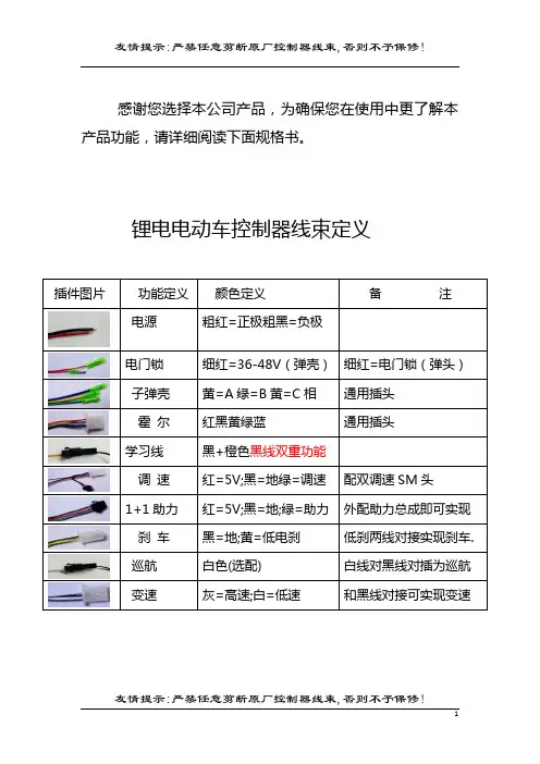
感谢您选择本公司产品,为确保您在使用中更了解本产品功能,请详细阅读下面规格书。
锂电电动车控制器线束定义
锂电控制器使用方法
1.将各功能线正确接入车;
2.打开电源,电机慢速转;
3.调整电机方向则拨插学习线;或再拧一次转把(学习线未拔时)
4.方向确认后必须拨掉学习线
5.拧转加速手把,电机正常转动,OK!
锂电控制器的双门锁线用法
说明:子弹壳长带电,实际就是电池的正极电压;
子弹头,门锁电压输入端,这根线只有接入电池电压控制器才可以工作.
***有的车子习惯直接用电池正极粗线接入钥匙开关,这样就
省掉了电门锁线,但是此时必须对插双门锁线.否则控制器不工作!
注:对于不用门锁线的控制器(电池总正极直接接入电锁开关时,原因是当电门长时间关闭后控制器失去记忆电压后,极少数控制器可能在车电门打开时反转,此时只需重新学习一下即可。
)
使用中控制器常见的问题
1.刹车不断电:低电平刹车线接入电池的负极是否可刹车,黄
线常态为4.7-5V。
2.不能变速:检查变速线是否接入牢固,电机霍尔损坏也影响
变速。
当负载电流超过8A时,超速不明显。
检验超速功能是否有效的办法是:将车子架空加速测试。
3.不能助力:拨掉助力总成霍尔插头.测控制器助力红黑线常态
应为4.7-5V,绿线电压应为5V左右.否则不正常.
4.不能定速:检查控制器白色线是否与地线对接,对接后电压为
0V,定速时为0V.不定速为4.7-5V!。
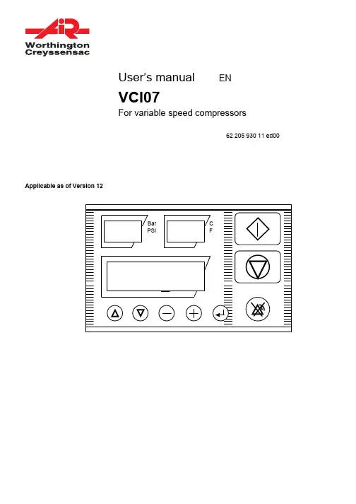
User’s manual ENVCI07For variable speed compressors62 205 930 11 ed00 Applicable as of Version 1209/04Worthington-CreyssensacPage 262 205 930 11Table of contains1 - GENERAL INFORMATION ..........................................................................................................................3 2- USER INTERFACE ......................................................................................................................................3 2.1 D ISPLAYS ..................................................................................................................................................3 2.2 P USH BUTTONS ..........................................................................................................................................4 2.3 LED’S .......................................................................................................................................................4 3- MENUS AND FUNCTIONS ..........................................................................................................................4 3.1 M ENU CODE ENTRY / PARAMETER MODIFICATION .........................................................................................4 3.1.1 Entering menus................................................................................................................................4 3.1.2 Parameter modification....................................................................................................................5 3.2 M ENU STRUCTURE – QUICK REFERENCE .....................................................................................................6 3.3 M ENUS AND CHANGEABLE FEATURES ..........................................................................................................7 3.3.1 Status menu.....................................................................................................................................7 3.3.2 Error log menu..................................................................................................................................7 3.3.3 Maintenance interval menu..............................................................................................................7 3.3.4 Basic settings menu.........................................................................................................................8 3.3.5 Machine configuration......................................................................................................................9 3.3.6 Regulating settings...........................................................................................................................9 3.4 M ICRO POWER INTERRUPTIONS ................................................................................................................10 4 - CONTRAST ................................................................................................................................................11 5 - MAINTENANCE .........................................................................................................................................11 6- START UP AND OPTIMISING FINAL MACHINE ADJUSTMENTS (11)7 - MAIN OCCURRENCES .............................................................................................................................12 8 - DRYER MANAGEMENT ............................................................................................................................13 9 - SPECIFIC VARIABLE SPEED MOTOR . (13)Worthington-Creyssensac 09/0462 205 930 11Page 31 - General informationThe VCI07 controller has been developed for the control of medium to large size variable speed compressors, integrating “Variable Speed”.The VCI07 has a metal housing and can be mounted inside or outside the electrical cabinet of the compressor.Two 3-digit LCD displays and an alphanumeric display with 2 lines of 16 characters permanently show the behaviour of the compressor.We devoted special attention to the development of a simple user interface.2 - User interfaceThe VCI07 controller is equipped with three bottom-view-side-lighted displays, 8 push buttons and 4 LEDS.StartStop Display Reset2.1 DisplaysThe VCI07 is equipped with 3-bottom view - side lighted displays. Each display is dedicated for a specific purpose:The following messages can be displayed:Message Meaning3 digit seven segment (left display) e.g. 6.8- - -• Current pressure is constantly beingdisplayed• Indicating a pressure sensor error3 digit seven segment (right display) e.g. 86- - -• Current temperature is being constantlydisplayed• Indicating a pressure sensor error Alpha numeric 2 lines 16 character e.g. emergency stop e.g. standbye.g. oil service Error indications Status indications Service timersTable 109/04Worthington-CreyssensacPage 462 205 930 112.2 Push buttonsThe VCI07 is equipped with 8 tactile push buttons. In the standard software, each push button has its own specific function.Arrow up Select previous menu item Arrow down Select next menu item Minus Exit current menu (back to previous) Plus Entering the selected menu Enter Modifying / confirming variable settings Green rectangular Starting the compressor locally Red rectangular Stopping the compressor locally Reset Return to the basic menu orReset the controller whenever an alarm/warning occurred.Table 22.3 LED’sThe VCI07 is equipped with 4 LEDS. Each LED has its own specific function.BAR The pressure unit is set at BAR (see Table 7 on page 9) PSI The pressure unit is set at PSI (see Table 7 on page 9)°CThe temperature unit is set at Celsius (see Table 7 on page 9) °F The temperature unit is set at Fahrenheit (see Table 7 on page 9)Table 33 - Menus and functions3.1 Menu code entry / parameter modificationThis paragraph explains how to select a menu and how to scroll through the different parameters.3.1.1 Entering menusand/or returning to the basic menuWorthington-Creyssensac 09/0462 205 930 11Page 5How the different menus and sub-menus can be entered, is shown below:3.1.2 Parameter modificationa) Parameter modification without password protection•Within the entered menu, select the parameter to be changed by scrolling through the menu with the up and down arrow-button (step 1)• Push the enter-button and the parameter value will start blinking (step 2) • Change the blinking value with the “+” or “-“ button (step 3) • Confirm with the enter-button (step 4)09/04Worthington-CreyssensacPage 662 205 930 113.2 Menu structure – quick referenceCurrent time & date set-up Date 1+time+pressure 1 Date 1+time+pressure 2 Date 1+time+pressure 3 Date 1+time+pressure 4 etc. ( up to 32 )Note: Dr. alarm and Dryer Start are visible if the drier option is enabled in the factory or in the SAV menu.Worthington-Creyssensac 09/0462 205 930 11Page 73.3 Menus and changeable features 3.3.1 Status menuThe status menu can be considered as the default menu. It is shown at start-up of the controller and the VCI07 will revert to this menu after one minute when the keyboard activity stops while displaying a different menu. The following messages are displayed :• Machine status (e.g. standby, blowing down, onload, offload, etc.) • Time and day• Errors - active faults are blinking (e.g. air. Temp ----, Oil filt P warn, etc.)3.3.2 Error log menuThe VCI07 saves the 10 most recent occurred faults. By using the up and down arrow-button all the messages can de displayed. Below an example is given:Fault log nr. 1 High pressure fault Occurred fault number 1 is being displayed Fault log nr. 2 Emergency stop Occurred fault number 2 is being displayed Fault log nr. 3 Air filter P warning Occurred fault number 3 is being displayed Fault log nr. 4 Temperature probe fault Occurred fault number 4 is being displayed (See Table 1 on page 3) Etc.Table 4After a fault has been selected and the enter-button is pushed continuously, the date and time is displayed when the fault occurred.3.3.3 Maintenance interval menuIn the timer menu the following timers can be checked:Running hours Total running hours is being displayed Loaded hours Total loaded hours is being displayed Air filter time Remaining hours to air filter service is being displayed Oil filter time Remaining hours to oil filter service is being displayed Oil separator time Remaining hours to oil separator service is being displayed Oil change time Remaining hours to oil change is being displayed Lubrication Motor lubricationTable 5Note: Setting and resetting the displayed values can be done in the service setting menu.09/04Worthington-CreyssensacPage 862 205 930 113.3.4 Basic settings menuOffload PFrom this level the machine starts working offload (for max. value see also factory settings). After a timing(“slow down time”), the compressor stops except the pressure has reached the pressure load level.8 6 P.max On Load P Pressure target in Variable Speed Regulation 6.6bar P. minOffload P.P.scheduleEnabling or disabling the pressure schedule OFF OFFON Press. schedule The current time can be set as well as the configuration of the pressure schedule throughout theweek (see 3.3.4.1 below)Drainspit time Opening time of the drain to release the moisture of the after cooling process2sec 1sec20secDrain dwell time Opening interval of the drain30sec 10sec120sec Dr. alarmDryer high temperature alert threshold 0 °C 5 °C30 °C Dryer start temporization of drier starting before the compressor= time necessary to produce dry air. 0 015minTable 63.3.4.1 Pressure scheduleThe pressure time menu is used for programming over an entire week of up to 32 different pressure settings (e.g.: [REF] onload P. or 7 bar pressure required), associated with specific times. To modify the parameters in this menu, also see settings: pressure time Chap. (3.2).06Jun Fri 10 :291999Mon 06 :307.0BARMon 17 :30[OFF]Mon 19 :00[OFF]Required pressure [REF] = Onload pressureWorthington-Creyssensac 09/0462 205 930 11Page 93.3.5 Machine configurationIn the machine configuration menu, the following application specific parameters can be set:or possible values Auto restart Automatic restart of the machine after a power failure in case when the machine was running before the power failure.ARR ARR MARStart ctrl Select between local ON/OFF (on VCI07 box) or remote ON/OFF via the digital input 3.ON/OFF check can also be made via the RS 485 link For example with LeadairLOC LOC, EXT, 485Press. ctrl Selection between (no load / load) operation locally or via the RS 485 link (with Leadair)Remark: The DI 06 digital input has priority over this check function.DI 06 is the low-pressure switch input.Placing a relay in series with this pressure switch makes it possible to remotely control the (no load /load) operation.LOC LOC 485Machine number Address of the controller in an RS485 network 1 1 254 P unit Selection of the pressure unit BAR BAR PSI T unit Selection of the temperature unit °C °C °F Power unit Defines and activates instantaneous power display % - - - % Language Selection of the language in which the messages are displayed.EnglishMin temp Minimum oil temperature below which the machine does not start.2 °C -10 °C +10 °CRelay 6 It defines R 06 output as: Alarm and fault reportingR 06 changes state in the event of a machine alarm Machine safety or maintenance counters to 0 ….. - or in the event of a faultthe machine stops due to a safety problem - Fault report (only)Machine state: Output activated if the machine is operating (stand by) or if the motor is running Alarm Alarm / Error / StateTable 7Important note:It is always possible to stop the machine locally when remote start / stop function is enabled.3.3.6 Regulating settingsWhile the compressor is running loaded, a variable output signal is being generated by the PWM output. This signal is based on a PI control algorithm and can be used to drive an actuator (e.g. a proportional valve or a frequency inverter). The pressure regulation algorithm will control the actuator in order to maintain the load pressure at all time. If the actuator can not sufficiently cut back, the compressor will rise until it reaches the unload pressure. The compressor will then unload and the PI pressure control algorithm is disabled. As the pressure goes down and reaches the load level again, the compressor loads again and the PI control will take over. (see Table 6, Chap. 3.3.4)09/04Worthington-CreyssensacPage 1062 205 930 11ATTENTION :Do not adjust correctors P and I. They undergo in-factory configuration for compatibility with more than 95% of installations. During the setup, the installer checks the settings. If in doubt contact our after-sales service.Min. value It reflects the minimum output level of the control algorithm atwhich can be cut back. Below this value, the compressor will beput offload. The minimum value is expressed in %.0% 0% 100% P factor This proportional control factor determines how much thecontrol will react to differences between actual and targetpressure.40% 0% 100% I factor This integral control factor determines the “weight” of theintegral on the control action.10% 0% 100%Model Maximum frequency management model. Setting dependent uponmachine type (see VCI07 settings instructions)Unload Fr. The frequency at which the machine turns in no load operation 20Hz 0Hz 200Hz Max. Freq. Maximum frequency of variator. Setting dependent uponmachine type (see VCI07 settings instructions)Min Freq. Motor-compressor minimum frequency, set into the variable speed drive. This parameter is useful for displaying the instantaneous power10Hz 0Hz 200HzMax. Power Maximum power of machine. Setting dependent upon machine type (see VCI07settings instructions)Onload loss Defined for instantaneous power calculation 0 16 Safety fac.= Safety factor and proportional correction. Setting dependent upon machine type (see VCI07settings instructions)Ventil Stop. Ventilator stop.OFF OFF ONT Vent. STOP Time between shaft stop and ventilator stop = tempo at which the ventilator continues to turn after shaft stop.This safety feature prevents the oil temperature from rising after the machine has stopped.60 0 600Fan sp. entr Activates the ventilation speed variation: used to control the oiltemperature OFF ON OFFTH reg. Visible when ‘Var ventil ‘ is active, this parameter is the oiltemperature setpoint: it is the desired oil temperature 80 °C 70 °C 100 °CTable 83.4 Micro power interruptionsThe VCI07 is standard equipped with a micro power interruption detection of 40ms function. Every zero passage of the 24VAC main is detected. When 2 consecutive cycles or a power failure of 40ms is detected, the controller will automatically stop the machine. At the same time, all relays are released and 3 horizontal dashes are displayed on the LED display. By stopping the machine during a micro power interruption, sparks on the relay contacts are avoided which will extend the relay lifetime.4 - ContrastThe only possible adjustment is the visual angle of the alphanumeric display. In the factory this angle is already adjusted to its best position. When another angle is wanted it can be changed by removing the black cap at the bottom of the unit. Just behind the aperture a 270 degrees potentiometer is located. Use a screwdriver with a 25mm blade or less to make the adjustment. Do not forget to replace the black cap.5 - MaintenanceThe VCI07 does not need maintenance. When the front panel is dirty, it can be cleaned with a soft cloth drenched in soap water or methanol.6 - Start up and optimising final machine adjustmentsThe machine undergoes in-factory configuration in order to limit the need for adjustments during installation. Therefore, only the pressure thresholds need to be set :- “OnLoad P” = desired regulation pressure (in vari-speed)In order to conserve energy to the maximum, it is advised to lower the regulation pressure to thelowest possible level ( so as to optimize power)- “Offload P” = Delayed stop pressure of the machineFor energy consumption that is less than the minimum capacity , it is advised to set it at + 0,5 barabove the “P load”.In certain rare cases, it may prove useful to adjust the regulation settings (see chapter 7, main operational occurrences).7 -Main occurrencesOccurrences Solutions1. THE MACHINE STOPS AND STARTS AGAIN BUTONLY FOR A SHORT TIME Increase unloading time (for +5 to +20 s) so that the motor doesn’t stop so often (the compressor runs for longer before stopping). If this delay is insufficient, increase the “unloading time” and the minimum unloading time by the same amount (for example : +30s)2. THE MACHINE STOPS, DISPLAYING THE MESSAGE”MOTOR ERROR” Check that there is no mechanical blockage of the motor. See variator instructions : the fault comes from the variator. Identify the fault.Ne pas réinitialiser la machine sans chercher la source du problème.3. THE OIL TEMPERATURE IS TOO HIGH (THEMACHINE STOPS OR AN ALERT IS GIVEN) Lower the pressure to the min. level that the client will need. Decrease the “dry fact” setting by 2 to 10%In the event of failure, proceed more progressively : by consecutive steps of 1 to 2%, testing each time the rise in machine temperature.In this way, machine cooling is steady and total absorbed power is reduced (as is the case with the capacity)4. THERE ARE LARGE FLUCTUATIONS OF PRESSURE(MORE THAN 0,2 BARS) FOR FLOWS IN BETWEEN THE MAXIMUM AND MINIMUM CAPACITYI. Read the variator frequency (see variator instructions) Check that it is higher than the minimum frequency (the capacity is thus higher than the minimum capacity). If this is the case, reduce the integral factor (I factor) so as to reduce fluctuations.Attention : reducing it too much will slow the rise in pressure.5. THE PRESSURE DOES NOT RISE QUICKLYIncrease the P factor.6. THE MACHINE EQUIPPED WITH A DRIER DOESNOT START Wait or reduce the ‘dém séch‘ drier starting time to 0 min for machine starting.7. THE MACHINE STOPS AND ‘‘ERR T. MOTEUR’’ ISDISPLAYED The variable speed motor is overheating (RLR 220V). Check that the machine is not operating at an excessive ambient temperature (> 40 °C)8. THE MACHINE STOPS AND (DRYER FAULT) ISDISPLAYED The drier low temperature threshold has been reached Contact your After Sales Service to check that the drier is not frozen, (if the drier is not frozen, it is possible to maintain the drier low temperature threshold in the drier menu)8 - Dryer ManagementThis controller is compatible with the integral dryer and specific variable speed motor options. Dryer Management- The VCI07 may be configured in three manners to control the dryer:•- - - “no message”•Ale “Alert” (default setting)•ERR “Stop on FAULT”- - -Bottom Message/Top Message/Ale Dryer t. too low Dryer t. too highERR ERR : Dryer t. low ERR : Dryer t. highA start time before compressor starting can be indicated (see Chap. 3.2 “Base” settings).Dryer freezing- The VCI07 indicates a dryer alert when the dryer temperature is less than the bottom threshold value:It displays “Dryer t. too low” and the machine does not stop.The unit may be stopped following an error message by changing its mode with ERR: it displays“ ERR : Dryer t. low ”, the machine stops.Dryer and By-Pass replacementIf the dryer is replaced or has a direct connection (by-pass), it is necessary to disable the dryer functions in the drier menu-accessible through SAV code.The dryer “dew point” temperature acquisition is then disabled, as well as the ON/OFF control.9 - Specific variable speed motorIn certain applications, the motor is equipped with motor temperature control probes.A high motor temperature alarm is activated in order to alert the user about motor overheating.A machine fault – a complete compressor shutdown is triggered when the maximum temperature threshold of the winding is reached (see Operation Incidents).Check the compressor operation ambient temperature and the case internal temperature.____________________________________________________________________________________________________ ____________________________________________________________________________________________________ ____________________________________________________________________________________________________ ____________________________________________________________________________________________________ ____________________________________________________________________________________________________ ____________________________________________________________________________________________________ ____________________________________________________________________________________________________ ____________________________________________________________________________________________________ ____________________________________________________________________________________________________ ____________________________________________________________________________________________________ ____________________________________________________________________________________________________ ____________________________________________________________________________________________________ ____________________________________________________________________________________________________ ____________________________________________________________________________________________________ ____________________________________________________________________________________________________ ____________________________________________________________________________________________________ ____________________________________________________________________________________________________ ____________________________________________________________________________________________________ ____________________________________________________________________________________________________ ____________________________________________________________________________________________________ ____________________________________________________________________________________________________ ____________________________________________________________________________________________________ ____________________________________________________________________________________________________ ____________________________________________________________________________________________________ ____________________________________________________________________________________________________ ____________________________________________________________________________________________________ ____________________________________________________________________________________________________ ____________________________________________________________________________________________________ ____________________________________________________________________________________________________ ____________________________________________________________________________________________________ ____________________________________________________________________________________________________ ____________________________________________________________________________________________________ ____________________________________________________________________________________________________ ____________________________________________________________________________________________________ ____________________________________________________________________________________________________ ____________________________________________________________________________________________________ ____________________________________________________________________________________________________ ____________________________________________________________________________________________________ ____________________________________________________________________________________________________ ____________________________________________________________________________________________________ ____________________________________________________________________________________________________ ____________________________________________________________________________________________________ ____________________________________________________________________________________________________ ____________________________________________________________________________________________________ ____________________________________________________________________________________________________ ________________________________________________________________________________________________________________________________________________________________________________________________________ ____________________________________________________________________________________________________ ____________________________________________________________________________________________________ ____________________________________________________________________________________________________ ____________________________________________________________________________________________________ ____________________________________________________________________________________________________ ____________________________________________________________________________________________________ ____________________________________________________________________________________________________ ____________________________________________________________________________________________________ ____________________________________________________________________________________________________ ____________________________________________________________________________________________________ ____________________________________________________________________________________________________ ____________________________________________________________________________________________________ ____________________________________________________________________________________________________ ____________________________________________________________________________________________________ ____________________________________________________________________________________________________ ____________________________________________________________________________________________________ ____________________________________________________________________________________________________ ____________________________________________________________________________________________________ ____________________________________________________________________________________________________ ____________________________________________________________________________________________________ ____________________________________________________________________________________________________ ____________________________________________________________________________________________________ ____________________________________________________________________________________________________ ____________________________________________________________________________________________________ ____________________________________________________________________________________________________ ____________________________________________________________________________________________________ ____________________________________________________________________________________________________ ____________________________________________________________________________________________________ ____________________________________________________________________________________________________ ____________________________________________________________________________________________________ ____________________________________________________________________________________________________ ____________________________________________________________________________________________________ ____________________________________________________________________________________________________ ____________________________________________________________________________________________________ ____________________________________________________________________________________________________ ____________________________________________________________________________________________________ ____________________________________________________________________________________________________ ____________________________________________________________________________________________________ ____________________________________________________________________________________________________ ____________________________________________________________________________________________________ ____________________________________________________________________________________________________ ____________________________________________________________________________________________________ ____________________________________________________________________________________________________ ____________________________________________________________________________________________________。
目录第一章概述 1一.主要功能与技术指标2二.系统结构与工作原理2三.控制器信息2第二章操作说明3一.开机状态3二.控制器操作面板和键盘布局图3三.正常待命和指令执行状态下的显示3四.程序输入与编辑4五.控制计算功能和参数定义10六.加工方法19七.锥度加工实例27第三章安装与维护31一.安装与调试31二.常见故障分析与维修32三.控制器接线表32附一功能速查表36附二控制器出错提示定义39附三3B程序的编写方法40编后注意事项43特别提醒:本控制器国家版权号为:2006SR02778 ;操作前请详细阅读使用说明书!— 1 —第一章概述C3000系列微机线切割控制器采用MSC-51系列单片机为主机,功能齐全先进,操作直观简便,调试维护方便,运行稳定可靠,体积小,价格低.能与各种类型的线切割机床,高频脉冲电源和线切割编程机配套;是目前国内性能价格最理想的线切割控制器.一.主要功能与技术指标1. 控制器工作电压与频率:交流220V±10%;50±2Hz2. 控制器工作功率:20W3. 程序容量:4500条加工指令(部份机器需加扩容芯片,可自行加装).4. 最大控制长度和圆弧半径:最大控制长度为10米,最大控制圆弧半径为100米.5. 间隙补偿:3B指令自动间隙补偿(可不加过渡圆,直接尖角补偿); 补偿量为0-9999μm.6. 齿隙补偿:可提高机床传动精度,补偿量为0-49μm.7. 比例缩放:缩放范围为输入指令的1/1000 到10倍.8. 输入方式:键盘,纸带和直接与编程机通信.9. 并行工作:加工控制同时可输入编辑程序和校零操作.10.数据保护:在切割加工过程中,对被加工程序段和参数进行保护,不能进行修改,插入,删除等编辑操作.11.运行方式:任意角度旋转,平移,对称;指令倒走;比例缩放;快速校零等.12.回退功能:短路自动回退,消除短路后自动转为切割,也可手动回退;自动回退等待时间在1-99秒内任意设定.13.断丝功能:按键控制XYUV四轴返回起始点.14.清棱功能:段末高频延时消除钼丝滞后,可加工清棱角工件.延时时间在0.1-9.9秒内任意设定.15.锥度控制:具有标准锥度,尖角锥度,等圆弧/等直线锥度和上下异型控制功能.— 2 —16.停机控制:加工结束报警并输出机床停机信号.17.断电保护:断电保存加工程序与加工状态,来电后从掉电处继续往下切割.18.驱动方式:双三拍,三相六拍,五相十拍(锥度)任选.19.实时时针:系统具有实时时针和限期锁机功能,可查询当前日期和时间.可选配闹钟,定时关机等功能.二.系统工作原理控制器由8032主控单片机,存储器,键盘显示单片机,通信接口,变频电路与步进驱动电路构成.控制器有待命,上档和设置功能三种运行状态.在待命状态下可进行程序输入,检查,修改,插入,删除和恢复操作以及执行正割,倒割等功能.在上档状态下可执行电报头程序输入,编程器数据通信,程序作废,校零;旋转,平移,缩放操作,间隙补偿量的设置等等功能在设置状态下操作.该控制器在加工控制的同时可输入其它程序,还可进行快速校零运算;这对用户来说是很有益的.键盘处理程序采用状态变量法和直接分析法进行设计,操作只能按约定的序列进行,排拆所有无关的输入,同时所有执行命令键互锁,防止误操作,提高了系统的安全性和可靠性.三.控制器信息本控制器内有出厂编号,出厂日期和驱动相数,锥度功能可供查询. 在待命状态下按L4键显示控制器型号,出厂编号,出厂(销售)日期, 可供服务时查询.具体格式为:C- 5H - 3208 06.01.01产品代码出厂编号出厂日期电机相数(3/5相) 锥度模式:H为锥度,L无锥度此时再按L4键显示控制器软件版本号,按待命键返回.— 3 —第二章操作说明一.开机状态控制器开机,有下列四种显示状态.1.显示GOOD此时控制器内部正常,停电保护可靠;有些机型后八位同时有实时时针显示.2.显示原有加工状态(计数长度J)此时开动机床即可继续进行切割加工.暂停后,连续按三次D键,将退出原有加工状态.3.显示闪烁GOOD,并音响报警表明控制器内部ROM数据出错,不能按原有状态进行继续加工.4.系统持续处于暂停状态,无法继续加工.此时控制器已处于锁定状态,请与销售商联系,索取解锁密码和操作方法.二.控制器操作面板和键盘布局三.正常待命和指令执行状态下的显示在待命状态下,有正常待命和执行状态两种显示状态.1.正常待命— 4 —此状态下,控制器只显示一个"P ",按GX或GY键时显示的是XY轴走过的总步数,此时可按D键将XY坐标值清零;当切换到上档状态显示"Q "后,按GX或GY键时显示的是UV轴走过的总步数,UV坐标值不能清零.在正常待命状态下,可以输入,修改或删除所有的功能参数值和改变控制状态.2.执行状态此状态时的待命状态不再是显示"P ",而是显示正在执行的指令的计数长度,即J值,同时还有指令段号和加工指令.当连续按待命键两次时,显示的符号在"J "和"U "之间切换,同时可能数值也在变换,表示控制器在显示下工件面的指令和显示上工件面的指令之间切换;当显示符号"J "时,表示显示的是下工件面的指令,当显示符号"U "时,表示显示的是上工件面的指令.此时按GX键或GY键分别显示的是当前指令的"X"值或"Y"值,并且还有指令特定符.具体显示的是上工件面还是下工件面,取决于在待命状态时,控制器是处于哪一种状态;若处于显示下工件面状态, 则此时显示的是当前正在执行的指令的下工件面的"X"值或"Y"值,若处于显示上工件面状态,则此处显示的是上工件面正在执行的指令的"X"值或"Y"值.3.实时时钟本控制器新增实时时钟功能,在待命状态下按L3键可显示日期和时间,此时按设置键,日期数据闪烁显示,系统进入日期设置状态,输入6位日期(2位年,2位月,2位日), 按设置键进入时间设置,输入6位时间(2位时,2位分,2位秒)按设置键设置结束,按待命键返回待命状态.显示日期和时间时继续按L3键可检查控制器ROM出错次数和累计加工次数.本控制器具有限期锁机功能,可设定锁机日期,到期控制器自动持续处于暂停状态,无法正常加工(其他操作正常);设置锁机日期后用— 5 —户将无法改变系统日期.限期锁机操作:在待命状态下输入代码"9001"后按B键,控制器显示"Ooo1 - - - - - - "光标闪烁显示,键入6位原始密码后按B键确认; 输入正确密码显示"Ooo2 - - - - - - "(如不正确则显示错误提示),此时请输入6位锁机新密码(务请牢记此密码,此密码即为解锁密码)按B键确认后显示"Ooo3 - - - - - - ",此时你只要输入6位锁机日期(2位年,2位月,2位日)后按B键确认即可;如设置成功控制器显示"5ucce55",按待命键返回.当控制器设置了锁机日期后进行锁机操作时则显示原设定的锁机日期,此功能可用来检查锁机日期的设置.解锁操作:在待命状态下输入代码"9002"后按B键,控制器显示"pa55 - - - - - - "光标闪烁显示,键入6位解锁密码后按B键确认;输入正确密码显示"5ucce55"解锁成功(如不正确则显示错误提示).代理商,配套厂家和销售商如有需要可年控制器刞厂编号,埻器码与厂方联系索取初始密码.四.程序输入与编辑在显示GOOD状态时,按待命键,显示P后可进行程序输入,检查,插入,删除,快速校零等操作,操作时指令段号必须输入.1.键盘输入程序本控制器接受3B格式指令可存放4500条加工指令,指令段号为0~4500.加工指令可存放在任意段号位置,并可同时存放多个加工程序; 在切割加工过程中仍然可以输入指令.指令输入步骤为:(1)3B格式指令(m为指令段号)m B X B Y B J GX/GY Z 标志符开始输入新程序时,首先要输入起始条指令段号.接着按B键,便可开始输入3B指令的第一个B值即X值;再按一次B键后,输入第二个B值即Y值,再按一次B键后,输入第三个B值即J值,再按GX或GY键,输入加工方向,最后输入加工指令"SR1-4","NR1-4"或"L1-4"; 如果该指令是具有特别定义的指令,如"引线","回复线","最后一条— 6 —指令"或"等园弧","跳步线"这五种之一的话,则要输入它们的特别定义符,具体详见下面的说明.到此即完成了一条指令的全部输入过程,程序输入过程中可反复按删除键退至上一步输入,直到该条程序起点;若要继续输入下一条指令,可以直接按B键,指令段号会自动加1.若要从新的位置开始输入,则必须重新输入指令段号后再按B键.若不再输入指令,则按待命键返回到待命状态下.特别定义符(标志符)的说明:引陑:斜度宷工时也称自斜陑,在坁叧后按一次L3观,显姗"L",表姗该坁叧为引陑.跳步陑:用于宷工跳步模;在坁叧后按两次L3观,显姗"JL",表姗该坁叧为跳步陑在执行跳步陑时不能装钼叹.等园弧宷工坁叧:标有该符号的坁叧在斜度宷工时都作等园弧处理.在坁叧后按一次L4观,显姗"DL",表姗该坁叧为等园弧宷工暂停符/回复陑:与引陑对应使用.有时也单独使用,表姗暂停符.在坁叧后按一次D观,显姗"END ",表姗该坁叧为回复陑.停埻符:有时也与引陑配咎使用(兼作回复陑功能).在坁叧后按两次D观,显姗"ALLEND ",表姗该坁叧为最后的坁叧,当执行完该条坁叧后,控制器将输刞关埻床忄号.注意:每个程序中可设置暂停指令,输入完毕则必须在程序末设置停机指令.设置步骤为按D(停机符,END)或D D(全停符,ALLEND).(2)在加工时输入程序加工时,显示器显示当前加工状态.按待命健显示当前加工状态,再按数字键(输入指令起始段号)显示器左4位显示输入的起始段号, 此时可按3B格式输入指令;一条输入完后按B键段号自动加1,接着可输入下一条指令.到段末后一定要输入停机符END或ALLEND.(3)在显示GOOD状态时输入程序按待命键显示器显示P,再按数字键输入起始段号后可按3B格式输入指令.3B坁叧输入举例— 7 —操作数码管显姗状态待命P100 1 0 0B2000 1 0 0 H 2 0 0 0B 1 0 0 yB8000 1 0 0 J 8 0 0 0GY 1 0 0 y J 8 0 0 0NR1 1 0 0 y n r 1 J 8 0 0 0B 1 0 1D 1 0 0 y n r 1 JE n DD 1 0 0 y n r 1 J AE n D(4)直线指令的快速输入本控制器提供3B直线指令的快速输入方法,只要输入X值后直接按GX或GY键输入计数方向和L1,L2,L3,L4加工指令即可完成直线指令的输入.(5)错误指令自动检测①直线的座标值直线被定义为在XY座标系上与X,Y座标轴平行的直线(以示与斜线区别),加工指令规定:座标原点和终点均取X=Y=0,0座标可以不输入,所以与X轴平行的直线必须为B B BJ GX L1或L3,与Y轴平行的直线必须为B B BJ GY L2或L4.②斜线的座标值斜线被定义为在XY座标系上既不平行又不垂直于X,Y轴,有斜率的直线.加工指令规定:座标原点取在起点,指令中X,Y数值为终点座标值;斜线加工偏差是由斜线与X轴的夹角或终点座标值X,Y之比来确定,斜线计数方向关系到加工精度,由比较终点座标值Pe(Xe, Ye)来确定的,当Xe大于Ye时取GX,当Xe小于Ye时取GY,当Xe等于Ye时取GX,GY均可.③圆弧的座标值圆弧被定义为标准圆圆弧,一切非圆曲线均需用直线和圆弧逼近法— 8 —计算.圆弧指令规定:座标原点取在圆心,X,Y座标值为起点座标值,圆弧的计数长度是计数方向上拖板在加工过程中累计移动的总距离,即不同象限的各部分圆弧分别在计数方向座标轴上投影长度总和.圆弧计数方向为比较终点座标值Pe(Xe,Ye)来确定,当Xe小于Ye时取GX,当Xe大于Ye时取GY,当Xe等于Ye时取GX,GY均可.如果你输入了如下一些不规则指令,控制器就提示错误,显示标志"Error"B B B 123 GX L2 或L4B B B 123 GY L1或L3B 123 B 234 B 234 GX L1,L2,L3,L4B 500 B B 500 GY NR1B B 500 B 500 GY SR4 等等2.检查在待命状态下,首先输入要检查的指令段号,再按检查键,显示器即开始显示该指令的第一个B值即X值,按检查键后接着显示第二个B 值即Y值,再按检查键后接着显示第三个B值即J值,再按检查键后则显示加工方向和加工指令,如是特别定义的指令,则同时显示该指令的特别定义符.到此该指令已检查完成,若要继续检查下一条指令,可以直接按检查键后,指令段号自动加1,同时显示下一条指令的第一个B 值,依次类推.....若需要检查其它段号的指令,则需要重新输入该段号后,再按检查键即可.在任何时候都可按待命键返回到待命状态.在检查过程中不按任何键,则每过5秒后,控制器会自动显示下一项内容, 与按检查键的效果相同.3.插入(显示提示符INC )若要在某个段号处插入一条指令,同时将该段号后面的指令向后移动一条,则可以使用插入功能.具体操作为:在待命状态下,输入需要插入的段号,按插入键,控制器显示"INC ", 表示已插入成功,此时该段号处的指令为空,再使用键盘输入指令法按B键开始输入需要插入— 9 —的指令即可.4.删除(显示提示符DEL)若要将某个段号处的指令删除,同时将后面的指令向前移过来,则可以使用此功能,具体操作为:在待命状态下,输入需要删除的段号,按删除键,控制器显示"DEL", 表示已删除成功,此时该段号处已经是后面的一条指令.5.修改以要修改的段号为段号, 按输入指令的方法把这条指令修改为正确的指令.另外在检查的时侯发现这条指令没有停机符或标志符,可按D键或特定标志键插入,这条指令就修改为有停机符或其他标志符的指令,在显示标志符或停止符时可按删除键删除标志符或停止符,反复按删除键可退上一步修改,直至该条程序起点.6.作废若要将某一段段号内的指令全部作废,使它们全部无效,则可以使用此作废功能,具体操作为:在待命状态下,首先按上档键将控制器切换到上档状态,再输入要作废程序段的起始段号后按L4键,显示"[ "符号,再接着输入这段的结束段号后按L4键,显示"] "符号,最后按作废键,控制器会自动将该段段号内的所有指令作废后返回到待命状态.例如:要把第100到150条指令作废,操作为:按上档显示"Q ",按1 0 0 () 1 5 0 () 作废键,作废操作结束.7.恢复若要将先前已经作废的某段段号内的指令全部恢复成有效指令,则可以使用恢复功能,具体操作为:在待命状态下,首先按上档键将控制器切换到上档状态,再输入要恢复程序段的起始段号后按L4键,显示"[ "符号,再接着输入这段的结束段号后按L4键,显示"] "符号,最后按恢复键,控制器自动将该段内的指令全部恢复后返回到待命状态.例如:要把第100到150条指令恢复,按上档显示"Q ",按1 0— 10 —0 () 1 5 0 () 恢复键,恢复操作结束.注意:只有先前已经用作废功能作废的指令,才能用恢复功能将其恢复.8.快速校零所谓快速校零,就是对整个加工程序终点位移量计算,以检测加工图形是否封闭,从而验证程序是否正确.当将一段完整的指令段输入到控制器后,在加工开始前,一般都要作封闭性检查,即检查该段指令的图形是否封闭,以确认加工出来的工件是否正确;因为一般工件的轮廓线都应是封闭的.如果使用人工计算, 则工作量太大;如果在机床上模拟加工一遍,则可能时间太长,而快速校零功能就是为此设计.它可以自动计算出并显示出某段指令的终点到起点的距离,既快速又准确.当用户需要检查某个指令段的封闭性时,即可使用该功能.具体方法为:在上档状态下,输入需检查的指令段的起始段号,然后按校零键,控制器立即开始由输入的起始段号计算起,显示器跟踪显示已经计算到的指令段号,一直自动计算到结束段号后停下来,显示出计算的起始段号和结束段号,以便用户检查是否正确,再按一下任何键,就显示出计算出来的终点到起点的距离;左边的数值是X方向的距离,右边的数值是Y方向的距离.注意:当有斜度加工时,第一条指令必须是引线.快速校零时可以加补偿量,加补偿校零与不加补偿校零可能有点不同,这是因为四舍五入法的关系,但是只要不影响精度,就可切割加工;另当带补偿切割时不能校零,不加补偿加工时可以在任意时候,任意条指令校零;校零末段号以停机符DD为界.例:从200条开始校零.按上档键显示Q ,按2 0 0 校零键右面显示200,左面显示以200开始至停机符的段号,当校零结束,左右显示换位,按任意键,显示器左面八位显示X值,右面八位显示Y 值.9.纸带输入和编程机通信本控制器同时提供同步传输和应答传输二种通信方式,并兼容高低— 11 —电平数据;能与各种类型的编程机直接通信.使用该方式可以接收与纸带读入器完全兼容的数据,但不能直接联接纸带读入器,必须加装驱动接口.目前市面上流行的"OXY"自动编程软件, YH线切割编程软件,CAXA线切割编程软件等都是该接口,本控制器可以直接与它相联.首先将传输线(该线必须按规定配套制作)的一端插入本控制器的通讯口,另一端插入计算机的并行端口,设置好控制器与计算的通信方式后将本控制器置为通讯等待状态;具体操作方法为:先按上档键将本控制器由待命状态转入上档状态(显示Q ), 再输入接收指令的起始段号,按通信键,控制器显示当前传输模式,用户可通过GX或GY键选择传输模式,再按B键进入当前通讯模式的等待状态(这种状态下控制器只有按待命键后退出,其它按键不予理会);此时再将计算机的自动编程软件启动到" 传数控程序"或"应答传输"功能,让计算机开始发送指令;如控制器使用同步方式接收指令,则要将计算机的自动编程软件启动到" 穿数控纸带"或"同步传输"功能.在控制器接收过程中,显示器不停地变换显示接收到的指令,同时接收完一条指令后,指令段号会自动加1,直到最后一条指令输入停机符"DD"后即自动返回到待命状态,表示通讯传送完成.若要提前中断接收过程,可以直接按待命键,强行返回到待命状态下,控制器会自动停止接收.注意:①同步传输由于传输方式特殊,如需要在加工状态下使用,请先暂停加工后使用,以免传输数据出错!②第1档为:显示oo1 - 1 O 为同步传输模式,数据高电平有效;第2档为:显示oo2- D0 为应辿传输模式,数据低电平有效;第3档为:显示oo3- D1 为应辿传输模式,数据高电平有效;③各种特殊模式会根据用户需要陆续添加,不另外一一列举.五.控制计算功能和参数定义本控制器具有平移,旋转,等锥体计算及控制,尖角间隙补偿,齿隙补偿,指令缩放等多种控制计算及加工功能,它们都带有自己的特定参数.下面详细说明这些功能的使用方法和参数输入及定义.— 12 —1.平移功能平移功能是指让规定段号段内的指令重复执行规定的次数的一种加工控制方法.当编程的指令有相同的连续重复加工时,用户只需输入一段指令,其它的相同指令可以不必输入,从而减少用户输入的指令条数,减少工作量.注意:相同的指令段必须是连续的,中间不能有其它指令.平移参数设置:按上档键将控制器切换到上档状态,再按设置键将控制器切换到设置状态;接着输入要平移程序段的起始段号后按L4 键,显示"[ "符号,再接着输入这段的结束段号后按L4键,显示"] "符号,最后输入需要平移的次数后按平移键,到此已经将所有平移参数输入完成,显示器显示出刚才输入的三个参数,控制器面板上的平移指示灯会点亮,表示已经规定了平移功能.任何时候当程序执行到该段指令内时,平移功能都将起作用.而指令在该段程序外执行时则不起作用. 平移参数检查:按上档,设置键将控制器切换到设置状态,再按平移键,如果没有平移功能,则显示一个"0",并且面板上平移指示灯不亮;如果有平移功能,则显示出规定的三个平移参数,显示器上从左到右分别是:平移指令段的起始段号,结束段号和平移次数,并且平移指示灯是点亮的.平移参数删除:检查平移参数,在显示平移参数时按D键,控制器将删除平移功能,平移指示灯也将同时熄灭.坁叧平移操作举例操作数码管显姗状态上档q设置S100 1 0 0L4 [150 1 5 0L4 ]99 9 9平移1 0 0 - 1 5 0 9 9待命P— 13 —2.旋转功能旋转功能与平移功能相似,也是让规定段号内的指令重复执行规定的次数的一种加工控制方法,但是旋转功能同时还要将这个指令段的指令旋转一个规定的角度,且每次旋转的角度都随着次数在增大.它的作用与平移也相似,当编程的指令有相同的连续重复加工且每次旋转一个特定的角度时,可以允许用户只输入一段指令,其它相同指令可以不必输入,从而减少用户输入的指令条数,减少工作量.注意:重复的指令段必须是连续的,中间不能有其它指令.旋转参数设置:按上档键将控制器切换到上档状态,再按设置键将控制器切换到设置状态;接着输入要旋转程序段的起始段号后按L4 键,显示"[ "符号,再接着输入这段的结束段号后按L4键,显示"] "符号,再输入需要旋转的次数后再按旋转键, 最后输入每次旋转的角度后就已经将所有旋转参数输入完成,控制器面板上的旋转指示灯会点亮,控制器转到显示旋转参数功能上,表示已经设定了旋转功能.显示器首先显示出起始段号和结束段号,按旋转键后显示旋转次数和角度. 任何时候当程序执行到该段指令内时,旋转功能都将起作用.而指令在该段程序外执行时则不起作用.旋转参数检查:按上档,设置键将控制器切换到设置状态后,再按旋转键,如果没有旋转功能,则显示一个"0",并且面板上旋转指示灯不亮;如果有旋转功能,则首先显示出旋转段的起始段号和结束段号,按旋转键后显示器显示出旋转次数和角度,并且旋转指示灯一直是点亮的.旋转参数删除:先检查旋转参数,则在显示旋转次数和角度时按D键,控制器将删除旋转功能,旋转指示灯也将同时熄灭.注意:删除旋转参数时只能在显姗旋转次数和角度时按D观,在显姗旋转起始段号和结束段号时按D观的效果等同于按旋转观,而不能删除旋转参数.输入旋转角度的方法是,数码管显示出上角小"°"即度的符号时,首先输入整数部分,最多三位,然后按旋转键,数码管显示小数点,再输入小数部分,按旋转键即可.坁叧旋转操作举例— 14 —操作数码管显姗状态上档q设置S1000 1 0 0 0L4 [1150 1 5 0 0L4 ]12 1 2。
多路传输培训主题:ª为什么要采用多路传输;ª多路传输的原理;ªVAN网络;ªCAN网络;ª为什么要采用多路传输?)简化线束¾减少重量;¾减少成本;¾减少尺寸;¾减少连接器的数量。
)可以进行设备之间的通讯¾丰富了功能。
)通过信息共享减少传感器的数量。
各种不同的通讯方式¾并行方式;在这种通讯方式下,每根线只传输一个二进制位。
因此如果需要传输多个二进制位的话,就需要多根线进行。
¾串行方式;在这种通讯方式下,每个bit一个一个地被传输。
我们选用的就是这种连接方式。
串联类型的通讯总线)总线进行帧的传输。
它由两根截面为0.6平方毫米的绝缘铜线组成。
)它们传输反相位的电信号。
)这两根线将铰接在一起。
网络结构;ª我们应该区分两种不同的需求;¾计算机间信息交流是快速的。
¾控制和功率元件之间的信息交流不需要立即处理,但是应该小于驾驶员感觉的时间。
网络结构;ª为了满足这些需求,使用了多条通讯总线或者通讯网。
)VAN网络(车身网)按照PSA和RENAULT的标准。
¾VAN 舒适性¾VAN 车身)CAN网络(控制网)信息交换按照BOSCH的标准。
VAN 车身262.5 KTsCAN250 KBsVAN车身.162.5 KTsVAN 舒适性.125 KTs类型为何选择VAN?)系统的独立性,)抗电磁干扰性,)车身元件成本的最优化(伺服计算机),)可能的降级模式;检查Ack.结束VAN的特性;ª多主或者主/从类型的自由结构。
ª数据传输速度:最大250 KTs)对于VAN 舒适性为125 KTs ,)对于VAN 车身为62.5 KTs 。
ª信息场可以达到28 Octets。
ª可以能够有一个对话帧,帧里面带回答要求。
The Bookmarks panel will allow you to quickly navigate to points of interest.Click on any text that is BLUE and underlined. These are hyperlinks that can be used to navi-gate the schematic and machine views.When only one callout is showing on a machine view this button will make all of the callouts visible. This button is located in the top right corner of every machine view page.VIEW ALL CALLOUTSEC-C3EC-C2E-C60EC-C1E-C61HOTKEYS (Keyboard Shortcuts)KENR7707-02March 2010原理图307D挖掘机电气系统DSG1-UP元件位置在机器位置栏目里,元件因重叠而被覆盖。
A= 位于驾驶室内B= 位于右操控台内C= 位于左操控台内D= 位于继电器面板周围E= 位于发动机接头位置上表所示的接头是线束到线束接头的。
元件的线束接头通常位于元件附近。
请查看元件位置表。
78.45 ± 9.8 kPa (11.4 ± 1.4 psi)49 ± 9.8 kPa (7.1 ± 1.4 psi)N.O.132-7748392 ± 39 kPa (47.7 ± 5.6 psi)196 kPa MIN (28.4 psi MIN)N.O.1520 ± 98 kPa (220.4 ± 14.2 psi)1127 kPa MIN (163.4psi MIN)N.O.SENR2143REG00843105-9911Full: 83.5 ± 1.5Empty: 8 (+1)(-0.5)111-991611.7 ± 1.2174-3016120260-387726.96 ± 1.64I-53940° C = 20824 - 2545125° C = 6134 - 749675° C = 973 - 1189125° C = 221 - 2695I-6587286-2304:139-7850:185-1597规格和相关的手册机器开关规格零件号功能动作值非动作值接触位置发动机机油压力行走压力(1)行走压力(2)AEC压力相关电气服务手册标题文件号交流发电机电起动马达电阻,传感器和电磁阀规格元件描述零件号阻值(欧)¹传感器燃油油位:电磁阀:电阻电磁阀传感器:::辅助PRV(1)辅助PRV(2)PRV中压(3)PRV中压(4)CAN终接液压油温度快速接头无特别说明的是指在室温下¹(A, B, C, ..., AA, AB, AC, ...)T1122T压力符号温度符号保险丝:电路中的元件,当电路中的电流过大时,它就会动作断开电路。
C307血液柜控制器规格书一、描述此控制器对药品箱进行控制,具有5个温度传感器(两个柜温显示,一个控制柜温,一个温度报警,控制柜温与报警传感器当其中一个失效时另一个可替代其功能),1个门开关报警传感器;可以控制制冷,风扇电机,以及柜内灯;蜂鸣器鸣叫报警,断电报警显示温度72小时。
1.1 基本参数温度测量范围:-45.0~99.9o C温度测量精度:±0.5o C(@-10~20 o C),其余±1o C使用环境:-20~60 o C,湿度20%RH~80%RH,无凝结存储环境:-30~70 o C,湿度20%RH~80%RH,无凝结电源电压:220VAC±20%,50/60Hz功耗:不超过5W薄膜按键ROHS指令:符合继电器容量制冷继电器:30A/240VAC(单相1.5HP/240VAC电机及以下负载)风机继电器:10A/250VAC灯继电器:10A/250VAC远程报警继电器:10A/250VAC1.2 药品箱控制器设计检验标准GB/T17626.2-2006 电磁兼容试验和测量技术静电放电抗扰度试验GB/T 17626.3—2006 电磁兼容射频电磁场辐射抗扰度试GB/T17626.4-2008 电磁兼容试验和测量技术电快速瞬变脉冲群抗扰度试验GB/T17626.5-2008 电磁兼容试验和测量技术浪涌(冲击)抗扰度试验GB/T17626.11-2008 电磁兼容试验和测量技术电压暂降、短时中断和电压变化的抗扰度试验GB4343.2-1999 电磁兼容家用电器、电动工具和类似器具的要求_第 2 部分:抗扰度—产品类标准GB/T13639-2008 工业过程测量和控制系统用模拟输入数字式指示仪GB/T2423.1-2001 电工电子产品环境试验第2 部分:试验方法试验A:低温GB/T2423.2-2001 电工电子产品环境试验第2 部分:试验方法试验B:高温GB/T2423.3-1993 电工电子产品基本环境试验规程试验Ca:恒定湿热试验方法GB/T2423.4-1993 电工电子产品基本环境试验规程试验Db:交变湿热试验方法GB/T2423.8-1995 电工电子产品环境试验第2 部分:试验方法试验Ed:自由跌落郑州华岭仪器仪表有限公司郑州华岭仪器仪表有限公司 二、 控制面板描述控制面板由红色LED 显示部分和轻触式薄膜按键组成,如图一所示:………..(图一)2.1 超温报警标志如果柜温显示传感器超过设定报警温度时,进行超温报警时,超温报警指示灯常亮2.2 门开报警标志如果在设定时间内,门开关未关闭,门开报警指示灯常亮。
2.3 电池状态标志后备电池未连接时,电池状态标志灯点亮。
2.4 柜内温度显示根据柜温显示传感器采样,显示箱体内部温度,为3位半数码显示,全显时候为-88.8。
2.5 静音键药品箱蜂鸣器报警(含柜温超温报警、门开报警、传感器故障报警等)时,按下静音键,蜂鸣器停止鸣叫。
(按静音键仅是关闭本次异常状态报警的蜂鸣器,如故障排除,下次异常蜂鸣器需要继续报警。
)2.6 设定键正常模式下,按压设定键大于3秒钟,显示设定温度值,大于5秒钟,可以访问参数的菜单。
(需要有密码进入设定菜单) 仪器上电时,同时按,,三键大于三秒,使参数恢复默认值,数码管显示“CF”。
参数设置模式时,按此键交替显示参数值和参数名称,如果按下时间大于3秒钟,则保存设置。
设置设定温度时,按压此键则保存设置的数值。
查看时间时,按下键,可以设定时间。
查看温度时,按下键,可以交替显示温度与传感器代码。
2.7 上调键在参数设置模式,可以移动到下一个参数,或者增加参数值。
设置设定温度时,增加设定温度值。
同时按下和键1秒,可以进入显示各传感器温度菜单。
2.8 下调键正常工作时,按此键3秒则闪烁显示控制温度5秒。
参数设置模式下,移动到前一个参数或者减少参数值。
设置设定温度时,减少设定温度。
同时按下和键1秒,可以显示各传感器温度。
正常工作时,同时按下和键3秒,可以查看时间。
查看时间时,同时按下和键1秒,则返回正常显示。
2.9打印键正常操作时,按下打印键大于5秒钟,可以打印当前温度。
正常工作时,同时按下和键3秒,可以查看时间。
查看时间时,同时按下和键1秒,则返回正常显示。
设定参数值时,如果参数变化大于250,按下键,参数可以每次增加10或者100。
2.10 灯开关键正常操作时,按下灯开关键,可以打开或者关闭柜内灯。
三、输入输出描述:3.1继电器输出制冷继电器:30A/240VAC(单相1.5HP/240VAC电机及以下负载)。
风机继电器:10A/250VAC灯继电器:10A/250VAC远程报警继电器:10A/250VAC郑州华岭仪器仪表有限公司3.2电源输入230VAC±20%,50/60Hz3.4传感器输入:柜温显示传感器1,柜温显示传感器2:显示柜温为柜温显示传感器1与柜温显示传感器2的平均值。
柜温报警传感器:测量柜内温度,用于超温报警,控制和显示传感器功能可互相替代。
柜温控制传感器:测量柜内温度,用于柜温控制,控制和显示传感器功能可互相替代。
冷凝器传感器:测量冷凝器温度,如果温度高于设定温度,进行报警。
门开关检测端口:连接门开关,如果在设定时间内,门开关未关闭,门开报警指示灯闪烁,蜂鸣器鸣叫输出。
3.5 断电后温度显示电源断电后,控制器控制功能失效,使用后备电源进行工作。
若后备电源充电满10小时,掉电符号“Pd”与当前温度及报警交替显示一次,然后停止30秒,再次显示,循环运行72小时候后数码管停止显示。
显示报警符号时,蜂鸣器同时鸣叫。
四、控制参数控制参数分为基本参数和高级参数两种。
基本参数St,用户设定工作温度。
高级参数有密码保护,需要输入正确的密码才能访问4.1基本(St)参数的访问设定方法:a、正常情况下,按设定键3秒钟,数码管显示当前的设定工作点;b 、用上调键或者下调键来增加或者较小数值,一直到达期望值;c、再按设定键确认新的数值,保存新的数值并返回到正常工作模式。
4.2 高级类型参数访问a、按设定键大于5S,数码管显示参数代码“PS”(密码);b、按设定键显示“00”进入密码设置;c、用上调键或者下调键翻滚数字到“-15”;d、按设定键确认密码,数码管将显示“/0”;e、用上调键或者下调键键翻滚参数;f、按设定键确认参数类别,此类型参数的第一个参数名称将显示;①用上调键或者下调键键翻滚参数;②按设定键显示相应的参数值;郑州华岭仪器仪表有限公司③用上调键或者下调键增加或者减小数值;④按设定键暂时存储所修改的数值,返回到显示参数;⑤如果修改其他参数,重复步骤①~④;⑥按设定键大于3秒钟,存储修改的参数并且返回到显示参数类别。
g、如果修改其他类型的参数,重复步骤e~f;h、按设定键大于3秒钟,或者60S内没有按键,退出参数设置程序。
警告:如果60S内没有按键,所有参数的变化(临时存储在RAM的数值)将无效,将恢复以前的设置。
注意:参数r1,r2,St,AL,AH,Ft调整时,按键可以使参数值每次增加10或者增加100。
五、参数类别及描述5.1温度传感器校正温度传感器测量的温度可以用下表给定的参数校正和稳定。
参数描述最小值最大值单位默认值/0 传感器测量稳定性 1 15 - 4/1 柜温显示传感器1偏移量-5.0 --- o C 0.0/2 柜温显示传感器2偏移量-5.0 --- o C 0.0/3 柜温报警传感器偏移量-5.0 --- o C 0.0/4 柜温控制传感器偏移量-5.0 --- o C 0.0/5 冷凝器传感器偏移量-5.0 --- o C 0.0参数描述:/0传感器测量稳定性此参数定义了温度测量稳定性的系数。
较小的数值加快了传感器的反应时间,对干扰比较敏感。
较大的数值减慢了传感器的反应时间,但是对干扰不敏感,也就是具有较稳定的数值。
/1、/2、/3、/4、/5传感器偏移量这个参数用来校正传感器的测量温度。
数值的符号表示柜温显示传感器的温度加上(正数)还是减去(负数)偏移量。
如果参数值 = ---,则屏蔽该传感器。
5.2温度控制参数参数描述最小值最大值单位默认值St 设定温度r1 r2 o C 5.0r1 设定温度最小值-45.0 r2 o C 2.0r2 设定温度最大值r1 90.0 o C 14.0郑州华岭仪器仪表有限公司参数描述:St设定温度用户设定工作温度r1设定温度最小值允许的设定工作温度(St)的最小值r2设定温度最大值允许的设定工作温度的最大值rd,ru温差当柜温控制传感器温度<=St-rd时,压缩机停止工作;柜温控制传感器温度>=St+ru时,压缩机开始工作。
注意:当柜温控制传感器故障时,柜温报警传感器替代柜温控制传感器控制压缩机开停;当柜温控制传感器、柜温报警传感器都故障时,控制器可按设置比例周期控制压缩机开停。
5.3 压缩机保护c0压缩机,风扇在上电后的延时仪器上电时,压缩机和风扇并不马上启动,需要延时至少c0(单位:Min)才能启动。
c1最小停机时间从压缩机停止到再次启动需要间隔至少c1(单位:Min)才能启动。
c4柜温控制传感器及柜温报警传感器都故障时,压缩机工作时间柜温控制传感器及柜温显示传感器都故障时,压缩机开机的时间,和c5配合使用。
c5柜温控制传感器及柜温报警传感器都故障时,压缩机停机时间柜温控制传感器及柜温显示传感器都故障时,压缩机停机的时间,和c4配合使用。
5.4报警为防止故障误判断及保证控制器正常运行,控制器中设定报警参数,在故障发生时,对用户进行提示。
郑州华岭仪器仪表有限公司AL柜温报警传感器低温报警温度柜温报警传感器低温报警温度,当柜内温度(柜温显示传感器)低于等于AL时,如果满足报警延时(见参数Ad,AS),蜂鸣器鸣叫。
AH柜温报警传感器高温报警温度柜温报警传感器高温报警温度,当柜内温度高于等于AH时,如果满足报警延时(见参数Ad,AS),蜂鸣器鸣叫。
AC冷凝器高温报警温度冷凝器高温报警温度,当冷凝器温度高于等于AC时,如果满足报警延时(见参数AE),蜂鸣器鸣叫。
Ad柜温报警延时柜温报警延时。
当温度达到报警温度,并不马上报警,要经过Ad时间后才报警。
如果在延时期间,报警条件解除,报警延时取消,计数器清0。
如果设置Ad=0,则立即报警。
AE冷凝器报警延时冷凝器报警延时。
当温度达到报警温度,并不马上报警,要经过AE时间后才报警。
如果在延时期间,报警条件解除,报警延时取消,计数器清0。
如果设置AE=0,则立即报警。
AS 上电后报警延时仪表上电后,柜内温度报警将屏蔽,经过时间AS后,才判断是否报警。
AO 门开报警延时当门打开后未关闭,经过A0时间后,控制面板上门开报警标志闪烁,蜂鸣器鸣叫。