第二章 无线通信基础
- 格式:pdf
- 大小:934.00 KB
- 文档页数:57
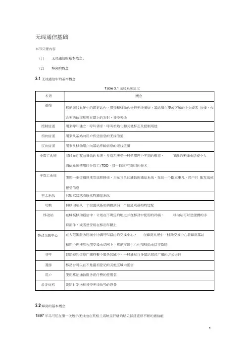
无线通信基础本节只要内容(1)无线通信的基本概念;(2)蜂窝的概念3.1无线通信中的基本概念3.2蜂窝的基本概念1897年马可尼在第一次展示无线电在英格兰海峡里行驶的船只保持连续不断的通信能力,标志着无线通信的开始。
但是无线通信由于其相关技术故障,在上世界 发展比较缓慢,知道贝尔实验室提出蜂窝的概念。
3.2.1背景知识介绍早期移动通信系统设计的目标: 在至高处建立单个大功率的发射机,面积。
至高处目的:尽可能保证视距传播。
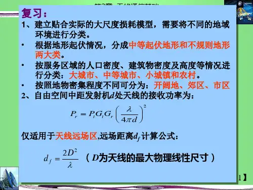
数据表明:建筑物能削弱无线信号P r10 lg 一二 20dBP o-20P 订 工一 =1010 =10 P .P =0.01P 0类似的,当衰减 30dB 时,P t = 0.001 P 0 优点:设计简单,覆盖面积大; 缺点:频谱利用率低,浪费严重P rdB =10 lg (—)其中P r 为实测到的功率,P 0为参考功率。
P )当电阻值不变时,由 P=E 2/R 得到其中E r 为电压实际测量值,E o 为电压参考值。
应用实例:70年代纽约的贝尔移动系统在1000平方英里(2*109平方米=2.6*10 3平方公里=3.88*10 6亩,苏州古城区 2*104亩)内最多支持12个同时呼叫。
矛盾:频谱资源有限、用户数量快速增加,无法满足需求 在此基础上产生蜂窝的概念。
蜂窝概念是一种系统级概念, 其思想是用许多小功率的发 射机(小覆盖区)来代替单个的大功率发射机(大覆盖区),每个小覆盖区只提供服务范围内的一部分覆盖,每个基站只分配可用信道的一部分, 有效降低了同频干扰,尽管存在邻频干扰,但是干扰降低了。
dB=10 lg=10 lg (空)=20 lg (旦)E O 60,70年代以前从而获得大的覆盖20-30分贝。
优点:(1)随着需求继续增长,蜂窝可以变的更小,这样,在不使用额外的频谱资源的同时,增加了额外的容量。
(2)每个用户设备都可以在使用相同蜂窝概念的地区接入网络。
3.2.2频率复用为整个系统中的所有基站选择和分配信道组的设计过程叫做频率复用或者频率规划。

无线通信基础_教学课件_2第二章无线信道的特性主讲人:张炜电子科学与工程学院军事通信工程系无线信道的损伤性无线信道的复杂性多种损伤。
加性的,乘性的;时间上的,频率上的;干扰,周围环境噪声;快转变的,慢转变的等等时变的信道信道的特性随时间不同而发生转变。
如何实现无线信道上的高质量通信,是一个具有挑战性的课题。
23>.1 多径传播环境线性时变信道模型信道相关函数大尺度路径损耗与阴影衰落小尺度多径衰落多径传播环境一、无线通信信号的传播方式二、接收信号中的四种效应4、多径时延(时间色散)五、多普勒频移(频率色散)多径传播环境(无线传播环境)多径传播环境一、无线通信信号的传播方式反射:当电磁波碰到比波长大得多的物体时发生反射,反射发生在地球表面、建筑物和墙壁表面。
绕射:当接收机和发射机之间的无线路径被尖锐的边缘阻挡时将发生绕射。
散射:当波穿行的介质中存在小于波长的物体而且单位体积内阻挡体的个数超级庞大时,将发生散射。
散射发生于粗糙表面、小物体或其他不规则物体。
直射:发射机信号无阻挡抵达接收机。
四种最大体传播方式:直射波障碍物绕射波入射波反射波电波的直射、反射和绕射发射天线多径传播环境一般情况下,相对于直射波,反射波、绕射波、散射波都比较弱。
(射线跟踪法)多径传播环境二、接收信号中的四种效应(1)阴影效应:由于大型建筑物和其它物体的阻挡,在电波传播的接收区域中产生传播半盲区。
多径传播环境远近效应:由于用户的随机移动性,发射机与接收机之间的距离也是在随机转变。
若发射机发射信号功率一样,那么抵达接收机时信号的强弱将不同,离接收机近者信号强,离接收机远者信号弱。
二、接收信号中的四种效应(2)多普勒效应:由于用户处于高速移动(如车载通信)中,传播频率的扩散而引发的,其频率扩散程度(多普勒频移)与用户运动速度成正比。
多径传播环境二、接收信号中的四种效应(3)XYdVS多普勒频率有正负吗?温习:无线通信信号的四种大体传播方式?什么是阴影效应?何谓半盲区?什么是多普勒效应?多普勒频移与用户运动速度之间的关系?多径传播环境二、接收信号中的四种效应(4)多径效应:由于接收者所处地理环境的复杂性,使得接收到的信号是多条从不同路径过来的信号的合成。

移动通信原理与系统习题答案移动通信原理与系统习题答案第一章简介1.1 移动通信原理与系统概述移动通信原理与系统是指利用无线电及其他相关技术,实现移动用户之间的通信和数据传输的系统。
其核心理论基础是无线通信原理和信号处理技术。
1.2 移动通信系统的发展历史移动通信系统的发展经历了从1G到5G的演进过程,每一代都引入了新的技术和服务,提高了通信效率和用户体验。
1.3 移动通信系统的基本组成移动通信系统由移动终端、基站子系统、核心网以及相关管理部分组成。
移动终端包括方式、数据卡等用户设备;基站子系统由基站、无线接入网和传输网构成;核心网是移动通信系统的核心部分,提供信令控制、数据传输等功能。
第二章无线通信原理2.1 无线信道特性无线信道的特性包括带宽、传输速率、衰落和多路径传播等,对无线通信系统的设计和优化有重要影响。
2.2 调制和多址技术调制技术用于将数字信号转换为模拟信号进行传输,以及将模拟信号转换为数字信号进行处理;多址技术用于多个用户共享有限的信道资源。
2.3 信噪比与误码率信噪比是信号功率与噪声功率之比,误码率是在给定信噪比下传输过程中出现错误的概率。
第三章移动通信系统的接入方式3.1 频分多址接入频分多址接入是指将频率资源划分为多个子载波,每个用户占用一个或多个子载波进行通信。
3.2 时分多址接入时分多址接入是将时间资源划分为多个时隙,不同用户在不同时隙进行通信。
3.3 码分多址接入码分多址接入是将用户信号通过不同的扩频码进行编码,以实现多用户共享信道。
第四章移动通信系统的网络架构4.1 无线接入网无线接入网是连接终端与基站的部分,包括射频传输、信号处理等功能。
4.2 传输网传输网是将基站与核心网进行连接的网络,承载用户数据和控制信号的传输。
4.3 核心网核心网是移动通信系统的核心部分,提供信令控制、用户数据传输等功能。
第五章移动通信系统的业务与技术5.1 语音通信业务语音通信是移动通信系统最基本的业务之一,主要通过语音编码技术和语音信道进行实现。

大二大三必修课无线通信教案一、课程简介无线通信是现代通信领域的重要分支,广泛应用于移动通信、卫星通信、物联网等各个领域。
本教案旨在通过讲授无线通信的基本原理、关键技术和应用场景,培养学生对无线通信系统的理解与设计能力,为学生日后的学习和工作奠定坚实的基础。
二、教学目标1. 理解和掌握无线通信的基本概念和关键技术。
2. 熟悉常见的无线通信系统及其结构。
3. 能够分析和评估无线通信系统的性能和容量。
4. 了解无线通信的未来发展趋势和应用领域。
三、教学内容和安排1. 第一章:无线通信基础知识1.1 无线通信的发展历程和应用领域1.2 无线信道的基本特性和参数1.3 无线通信中的调制与解调技术1.4 无线通信中的多址技术1.5 无线通信系统的组成和基本原理2. 第二章:无线传输技术2.1 传输介质:空气接口和地面接口2.2 传输技术:无线电传输、红外线传输、激光传输等 2.3 信道编码和解码技术2.4 信道调制和解调技术3. 第三章:无线接入技术3.1 蜂窝通信系统和基站技术3.2 无线局域网(WLAN)和Wi-Fi技术3.3 蓝牙和近场通信(NFC)技术3.4 卫星通信和移动卫星通信技术4. 第四章:无线网络和协议4.1 无线网络的体系结构和组网方式4.2 网络层协议和路由选择算法4.3 传输层协议和流量控制技术4.4 应用层协议和网络安全5. 第五章:无线通信系统设计和性能评估5.1 系统容量和覆盖范围的估算5.2 信道质量评估和反馈技术5.3 基站布局和天线系统设计5.4 系统仿真和性能优化四、教学方法和手段1. 理论授课:通过讲解、演示和示例分析,介绍无线通信的基本原理和关键技术。
2. 实践操作:组织学生进行无线通信系统的实际操作和实验,巩固理论知识。
3. 课堂讨论:引导学生参与讨论,思考无线通信技术的发展趋势和应用前景。
4. 课程作业:布置相关的课程作业和研究课题,培养学生的自主学习和解决问题的能力。
无线通信基础教学设计背景介绍随着移动互联网的飞速发展,无线通信技术在人们日常生活中扮演着越来越重要的角色。
因此,对于掌握无线通信基础知识的需求也越来越迫切。
本文旨在介绍无线通信基础教学设计,为广大学生和相关从业人员提供了解无线通信基础知识的途径。
教学目标在完成本教学设计后,学生应该掌握以下知识:1.无线通信的基本概念和原理;2.无线通信的传输媒介和信号传输方式;3.无线通信的调制与解调技术;4.无线通信中常用的天线类型和性能参数;5.无线通信的安全保障措施。
教学内容第一章:无线通信的基本概念和原理1.无线通信的概念和发展历程;2.无线通信系统的组成和基本原理;3.无线通信的传输媒介和信号传输方式;4.无线通信中常见的信道模型。
第二章:无线通信的调制与解调技术1.无线信号的调制原理;2.常见的数字调制技术及其应用;3.常见的模拟调制技术及其应用;4.无线信号的解调原理及其实现。
第三章:无线通信中常用的天线类型和性能参数1.天线的基本原理和种类;2.天线的性能参数及其意义;3.天线的特殊应用。
第四章:无线通信的安全保障措施1.无线通信的安全保障需求;2.无线通信的安全保障措施和方法;3.无线通信安全保障的管理和维护。
教学方法在教学过程中,采用以下方法:1.课堂讲授:采用大型投影仪,PPT等多媒体教学工具来辅助教学,课程内容带有实际案例,并由实验演示加深学生对相关知识点的理解;2.实验演示:在教学过程中,加强实验教学环节,提高学生的实践能力;3.考试评测:在教学结束后,进行期末考试,对学生进行综合测评。
教学资源1.无线通信教材:选用经典教材,如《现代无线通信技术》等;2.实验设备:无线通信实验设备,包括天线、移动通信设备等;3.教学媒体设备:多媒体教室、无线通信模拟软件等。
教学成果经过本课程的学习,学生将能够掌握无线通信领域的基础理论知识,了解无线通信专业的发展趋势和规划,具备研究和解决无线通信工程实际问题的能力。
©2009 Guangming Song-Southeast UniversityOutline无线通信的基本概念模拟信号与数字信号带宽与通道容量信号编码与调制电磁信号电磁信号是一个时间函数电磁信号也可以表达为一个频率函数 信号由不同的频率分量组成时域模拟信号-信号强度随时间平滑变化 信号中无暂停与中断数字信号-信号强度在某一个时间段内维持一个常量,在下一个时间段又跳转到另一个常量时域时域周期信号-信号波形随时间周期重复变化 模拟或数字信号中最简单的一种s (t+T) = s (t) -∞< t< +∞T为信号周期非周期信号-信号波形不随时间周期重复变化时域时域Peak amplitude (A)-maximum value or strength of the signal over time; typically measured in voltsFrequency (f)-Rate, in cycles per second, or Hertz (Hz) at which the signal repeatsPeriod (T) -amount of time it takes for one repetition of the signalT= 1/fPhase (φ)-measure of the relative position in time within a single period of a signalWavelength (λ) -distance occupied by a single cycle of the signalOr, the distance between two points of corresponding phase of two consecutive cycles时域General sine waves(t) = A sin(2πft+ φ)Figure 2.3 shows the effect of varying each of the three parameters(a) A= 1, f= 1 Hz, φ= 0; thus T= 1s(b) Reduced peak amplitude; A=0.5(c) Increased frequency; f= 2, thus T= ½S(d) Phase shift; φ= π/4 radians (45 degrees)note: 2πradians = 360°= 1 period时域Fundamental frequency -when all frequency components of a signal are integer multiples of one frequency, it’s referred to as the fundamental frequencySpectrum -range of frequencies that a signal containsAbsolute bandwidth -width of the spectrum ofa signalEffective bandwidth (or just bandwidth) -narrow band of frequencies that most of the signal’s energy is contained inAny electromagnetic signal can be shown to consist of a collection of periodic analog signals (sine waves) at different amplitudes, frequencies, and phasesThe period of the total signal is equal to the period of the fundamental frequencyThe greater the bandwidth, the higher the information-carrying capacityConclusionsAny digital waveform will have infinite bandwidthBUT the transmission system will limit the bandwidth that can be transmittedAND, for any given medium, the greater the bandwidth transmitted, the greater the costHOWEVER, limiting the bandwidth creates distortionsData Communication TermsAnalog -continuousDigital -discreteData -entities that convey meaning, or informationSignals -electric or electromagnetic representations of dataTransmission -communication of data by the propagation and processing of signalsAnalogVideoAudio DigitalTextIntegersA continuously varying electromagnetic wavethat may be propagated over a variety of media, depending on frequencyExamples of media:Copper wire media (twisted pair and coaxial cable)Fiber optic cableAtmosphere or space propagationAnalog signals can propagate analog and digital dataA sequence of voltage pulses that may betransmitted over a copper wire mediumGenerally cheaper than analog signalingLess susceptible to noise interferenceSuffer more from attenuationDigital signals can propagate analog and digital dataDigital SignalsAnalog DataHow to Choose Data and Signal Combinations Digital data, digital signalEquipment for encoding is less complex and less expensive than digital-to-analog equipmentAnalog data, digital signalConversion permits use of modern digital transmission and switching equipmentDigital data, analog signalSome transmission media will only propagate analog signalsExamples include optical fiber and satelliteAnalog data, analog signalAnalog data easily converted to analog signalTransmit analog signals without regard to contentAttenuation limits length of transmission linkCascaded amplifiers boost signal’s energy for longer distances but cause distortionAnalog data can tolerate distortionIntroduces errors in digital dataConcerned with the content of the signalAttenuation endangers integrity of dataDigital SignalRepeaters achieve greater distanceRepeaters recover the signal and retransmitAnalog signal carrying digital dataRetransmission device recovers the digital data from analog signalGenerates new, clean analog signalChannel CapacityImpairments, such as noise, limit data rate that can be achievedFor digital data, to what extent do impairments limit data rate?Channel Capacity–the maximum rate at which data can be transmitted over a given communication path, or channel, under given conditionsConcepts Related to Channel CapacityData rate -rate at which data can be communicated (bps)Bandwidth -the bandwidth of the transmitted signal as constrained by the transmitter and the nature of the transmission medium (Hertz)Noise -average level of noise over the communications pathError rate -rate at which errors occurError = transmit 1 and receive 0; transmit 0 and receive 1Nyquist BandwidthFor binary signals (two voltage levels)C = 2BWith multilevel signalingC= 2B log2MM= number of discrete signal or voltage levelsSignal-to-Noise RatioShannon Capacity FormulaEquation:Represents theoretical maximum that can be achievedIn practice, only much lower rates achieved Formula assumes white noise (thermal noise)Impulse noise is not accounted forAttenuation distortion or delay distortion not accounted for()SNR 1log 2+=B CSpectrum of a channel between 3 MHz and 4 MHz ; SNR dB = 24 dBUsing Shannon’s formula()251SNR SNR log 10dB 24SNR MHz1MHz 3MHz 410dB ====−=B ()Mbps 88102511log 10626=×≈+×=CHow many signaling levels are required?()16log 4log 102108log 222662==××=×=M MMMB CWhat limits bandwidth?Sounds like higher bandwidth signals are a good idea.So ... Why not transmit at the highest bandwidth possible?Answer: The FCC!Bandwidth AllocationIn the U.S., the FCC is responsible for allocating radio frequencies.Why allocate the radio spectrum?Prevent interference between different devicesIt would be unfortunate if the local TV station interfered with police radio...Generally, any transmitter is limited to a certain bandwidthe.g., a single 802.11 channel is 30 MHz “wide”FCC also regulates the power and placement of transmittersConsumer devices generally limited to transmitting < 1 W of powerCan't have two TV stations on channel 5 next to each otherIn China, 信息产业部无线电管理局Classifications of Transmission MediaTransmission Medium-Physical path between transmitter and receiverGuided MediaWaves are guided along a solid mediumE.g., copper twisted pair, copper coaxial cable, opticalfiberUnguided MediaProvides a means of transmission but does not guide electromagnetic signalsUsually referred to as wireless transmissionE.g., atmosphere, outer spaceUnguided MediaTransmission and reception are achieved by means of an antennaConfigurations for wireless transmission DirectionalOmnidirectionalRadio frequency range30 MHz to 1 GHzSuitable for omnidirectional applicationsMicrowave frequency range1 GHz to 40 GHzDirectional beams possibleSuitable for point-to-point transmissionUsed for satellite communicationsInfrared frequency rangeRoughly, 3x10¹¹to 2x10¹⁴HzUseful in local point-to-point multipoint applications within confined areasTerrestrial MicrowaveDescription of common microwave antenna Parabolic "dish", typical size: 3 m in diameterFixed rigidly and focuses a narrow beamAchieves line-of-sight transmission to receiving antennaLocated at substantial heights above ground levelApplicationsLong haul telecommunications serviceShort point-to-point links between buildingsSatellite MicrowaveDescription of communication satelliteMicrowave relay stationUsed to link two or more ground-based microwave transmitter/receiversReceives transmissions on one frequency band (uplink), amplifies or repeats the signal, andtransmits it on another frequency (downlink)ApplicationsTelevision distributionLong-distance telephone transmissionPrivate business networksBroadcast RadioDescription of broadcast radio antennas OmnidirectionalAntennas not required to be dish-shapedAntennas need not be rigidly mounted to a precise alignmentApplicationsBroadcast radioVHF and part of the UHF band; 30 MHZ to 1GHzCovers FM radio and UHF and VHF televisionCarrier WaveHow do we send information in a radio signal?Carrier waveAn RF signal –usually a sinusoid –that carries informationCarrier is usually a much higher frequency than the information itself!Example: 2.4 GHz 802.11b networks carry a lot less than2.4 GBit/sec of data....Rather, carry up to 11 MBit/sec of informationWhy use a carrier?Easier to generate a sinusoid signal, and it will travel further. Carrier wave frequencyThe frequency of a radio transmission is the center frequency of the carrierActual frequency of the carrier changes over time, e.g., with FM transmissionHow do we encode information in a carrier wave?An information signal must be modulated onto the carrier waveThat is, we must modify the carrier wave in some way...Receiver must demodulate the carrier to get back the original signalAmplitude Modulation (AM)Modify the amplitude of the carrier with respect to the amplitude of the signalFrequency Modulation (FM)Modify the frequency of the carrier with respect to the amplitude of the signalInformation SignalAmplitude Modulation(AM)Information SignalFrequency Modulation(FM)How do we modulate digital signals?Amplitude shift keying (ASK)“0”bit is the absence of the carrier (flat signal)“1”bit is the presence of the carrier with some fixed amplitude Frequency shift keying (FSK)“0”bit is carrier at frequency f0“1”bit is carrier at frequency f1Other modulation techniquesLots of other modulation schemes are used in practiceEach has different properties in terms of resiliency to noise, interference, multipath effects, etc.Gaussian Frequency Shift Keying (GFSK)Binary 1 is a positive frequency shift from base frequencyBinary 0 is negative frequency shift from base frequencyUsed in BluetoothPhase shift keying (PSK)The phase of the carrier is used to represent data“Differential quadrature phase shift keying”(DQPSK) used by 802.11b networksFour phase levels representing 00, 01, 10, and 11 bit sequencesQuadrature Amplitude Modulation (QAM)Combination of AM + PSKUse two amplitudes and 4 phase levels to represent each sequence of 3 bitsDecibels and Signal StrengthThere will be a loss, or attenuation in signal transmissionAmplifiers will impart a gain to compensateRatio between two signal power levels is often measured in decibels (dB):gain(dB) = 10log10(P out/ P in)loss(dB) = –10log10(P out/ P in) = 10 log10(P in/P out)Where P out is the output power level, and P in is the input power levelExampleSignal with power level 10mW transmitted over a wireless channel.Receiver gets a signal of 2mW.Loss = 10 lg(10/2) = 10(0.699) = 6.99 dB。