华为S9306配置规范
- 格式:doc
- 大小:244.00 KB
- 文档页数:21

IP网络资源分配原则公司目前采用MSTP环、光纤、以太环网三种组网方式,承载DIA、CPN、NGN、IPTV、家庭网关等业务。
在一些接入机房,采用基于以太网的无源光网络PON作为覆盖最后一公里的接入方案。
针对不同的组网方式,特制定以下IP网络资源分配原则。
一、基于MSTP环、光纤、以太环网IP网络资源分配1. 新开商客大楼,分配传输MSTP/光纤/以太环网网络资源、核心/汇聚IP路由器端口资源;汇聚交换机私网管理IP地址。
2.新开小区,分配传输MSTP/光纤/以太环网网络资源、核心/汇聚IP路由器端口资源;小区业务VLAN。
3. 采用ONU/MUD/AG等综合接入设备的商客大楼和小区分配传输MSTP/光纤/以太环网网络资源、核心/汇聚IP路由器端口资源;ONU/MUD/AG设备管理IP、管理VLAN、业务IP、业务VLAN。
(1)对于只开通语音业务的ONU/MUD/AG设备路由:ONU/MUD/AG—以太环网/MSTP环/光纤—NGN城载网(2)对于同时开通语音及数据业务的ONU/MUD/AG设备,一台设备分配两条上联路由。
路由a:【ONU/MUD/AG设备—以太环网/MSTP环/光纤—IP城域网】(用于数据业务)路由b:【ONU/MUD/AG设备—以太环网/MSTP环/光纤—NGN城载网】(用于语音业务)由于NGN城载网覆盖区域有限,有些ONU/MUD/AG设备无法直达NGN城载网,对于这类接入点,采用【ONU/MUD/AG—以太环网/MSTP 环/光纤—IP城域网— NGN城载网】路由方式开通。
4. IP网络资源优先级业务类型带宽利用率介质(优先级由高到低)CPN 高以太环网、光纤、MSTPDIA 较高以太环网、MSTP、光纤IPTV 高以太环网、光纤、MSTPNGN 低以太环网、MSTP、光纤5.家庭网关类业务家庭网关类业务路由进IP城域网,采用IP城域网NGN-zhinengwang业务VPN,业务IP地址段10.53.64.0-127.0/24(64C)。

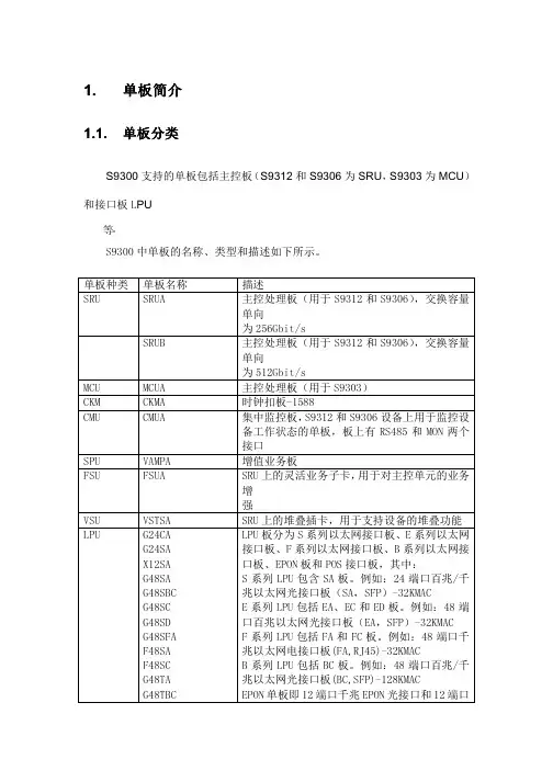
Realize Your Potential华为技术有限公司Huawei S9300系列交换机详版彩页01 Huawei S9300系列交换机Huawei S9300系列是华为公司面向融合多业务的网络架构而推出的新一代高端智能T比特核心路由交换机。
该产品基于华为公司智能多层交换的技术理念,在提供稳定、可靠、安全的高性能L2/L3层交换服务S9303 S9306 S9312S9310产品特点S9300敏捷交换机,让网络更敏捷地为业务服务• S9300 敏捷单板内置高速灵活的以太网络处理器ENP,针对以太网专属设计。
借其灵活的报文处理及流量控制能力,深入贴近业务,满足现在及未来的各种挑战,助力客户构建弹性扩展的网络。
ENP芯片采用全可编程架构,可以完全自定义流量的转发模式、转发行为和查找算法。
通过微码编程实现新业务,客户无需更换新的硬件,快速灵活,6个月即可上线,而传统AS I C 芯片采用固定的转发架构和转发流程,新业务无法快速部署,需要等待1~3年的硬件支持。
• 凭借敏捷单板,S9300支持统一用户管理功能,屏蔽了接入层设备能力和接入方式的差异,支持802.1X/ MAC/Portal等多种认证方式,支持对用户进行分组/分域/分时的管理,用户、业务可视可控,实现了从“以设备管理为中心”到“以用户管理为中心”的飞跃。
• 凭借敏捷单板,S9300支持iPCA网络包守恒算法,改变了传统利用模拟流量做故障定位的检测模型,可对任意业务流随时随地逐点检测网络质量,无需额外开销;可在短时间内立刻检测业务闪断性故障,检测直接精准到故障端口,实现从“粗放式运维”到“精准化运维”的大转变。
• 凭借敏捷单板,S9300支持1588v2和同步以太,满足网络设备间的高精度时间同步,相比GPS的时间不同方案,提升安全的同时降低成本。
创新的CSS集群技术• S9300可通过集群卡连接和业务口连接两种方式实现虚拟化。
CSS集群创新性采用交换网集群技术,提供业界主机间最大的320G集群带宽;业务口集群支持成员机通过LPU上的普通业务口连接,将LPU上的业务口配置为堆叠物理成员端口后加入逻辑堆叠端口,通过SFP+光模块和光纤或SFP+堆叠线缆将堆叠物理成员端口连接。
华为交换机基本配置命令一、单交换机VLAN划分命令命令解释system 进入系统视图system-view 进入系统视图quit 退到系统视图undo vlan 20 删除vlan 20sysname 交换机命名disp vlan 显示vlanvlan 20 创建vlan(也可进入vlan 20)port e1/0/1 to e1/0/5 把端口1-5放入VLAN 20 中disp vlan 20 显示vlan里的端口20int e1/0/24 进入端口24port access vlan 20 把当前端口放入vlan 20undo port e1/0/10 表示删除当前VLAN端口10disp curr 显示当前配置二、配置交换机支持TELNETsystem 进入系统视图sysname 交换机命名int vlan 1 进入VLAN 1ip address 192.168.3.100 255.255.255.0 配置IP地址user-int vty 0 4 进入虚拟终端authentication-mode password (aut password) 设置口令模式set authentication password simple 222 (set aut pass sim 222) 设置口令user privilege level 3(use priv lev 3) 配置用户级别disp current-configuration (disp cur) 查看当前配置disp ip int 查看交换机VLAN IP配置删除配置必须退到用户模式reset saved-configuration(reset saved) 删除配置reboot 重启交换机三、跨交换机VLAN的通讯在sw1上:vlan 10 建立VLAN 10int e1/0/5 进入端口5port access vlan 10 把端口5加入vlan 10vlan 20 建立VLAN 20int e1/0/15 进入端口15port access vlan 20 把端口15加入VLAN 20int e1/0/24 进入端口24port link-type trunk 把24端口设为TRUNK端口port trunk permit vlan all 同上在SW2上:vlan 10 建立VLAN 10int e1/0/20 进入端口20port access vlan 10 把端口20放入VLAN 10int e1/0/24 进入端口24port link-type trunk 把24端口设为TRUNK端口port trunk permit vlan all (port trunk permit vlan 10 只能为vlan 10使用)24端口为所有VLAN使用disp int e1/0/24 查看端口24是否为TRUNKundo port trunk permit vlan all 删除该句四、路由的配置命令system 进入系统模式sysname 命名int e1/0 进入端口ip address 192.168.3.100 255.255.255.0 设置IPundo shutdown 打开端口disp ip int e1/0 查看IP接口情况disp ip int brief 查看IP接口情况user-int vty 0 4 进入口令模式authentication-mode password(auth pass) 进入口令模式set authentication password simple 222 37 设置口令user privilege level 3 进入3级特权save 保存配置reset saved-configuration 删除配置(用户模式下运行)undo shutdown 配置远程登陆密码int e1/4ip route 192.168.3.0(目标网段) 255.255.255.0 192.168.12.1(下一跳:下一路由器的接口)静态路由ip route 0.0.0.0 0.0.0.0 192.168.12.1 默认路由disp ip rout 显示路由列表sw1(三层交换机):int vlan 10 创建虚拟接口VLAN 10ip address 192.168.10.254 255.255.255.0 设置虚拟接口VLAN 10的地址int vlan 20 创建虚拟接口VLAN 20ip address 192.168.20.254 255.255.255.0 设置虚拟接口IP VLAN 20的地址注意:vlan 10里的计算机的网关设为 192.168.10.254vlan 20里的计算机的网关设为 192.168.20.254[S9306-GigabitEthernet2/0/42]dis this#interface GigabitEthernet2/0/42 原先的为trunk,port link-type trunkport trunk allow-pass vlan 2 to 4094Duplex {auto/half/full}Speed {auto/10/100/1000}#interface GigabitEthernet2/0/42 现在改为accessundo port trunk allow-pass vlan allport trunk allow-pass vlan 1port link-type accessport default vlan 10Stp enableStp priority 4096Stp root {primary/secondary}华为路由器交换机配置命令:路由器命令[Quidway]displayversion;显示版本信息[Quidway]displaycurrent-configuration;显示当前配置[Quidway]displayinterfaces;显示接口信息[Quidway]displayiproute;显示路由信息[Quidway]sysnameaabbcc;更改主机名[Quidway]superpasswrod123456;设置口令[Quidway]interfaceserial0;进入接口[Quidway-serial0]ipaddress;配置端口IP地址[Quidway-serial0]undoshutdown;激活端口配置ospf[S9300-A] router id 1.1.1.1[S9300-A] ospf 100[S9300-A-ospf-100] area 0[S9300-A-ospf-100-area-0.0.0.0] network 192.168.0.0 0.0.0.255 [S9300-A-ospf-100-area-0.0.0.0] quit[S9300-A-ospf-1] area 1[S9300-A-ospf-100-area-0.0.0.1] network 192.168.1.0 0.0.0.255 [S9300-A-ospf-100-area-0.0.0.1] quit[S9300-A-ospf-1] quit。
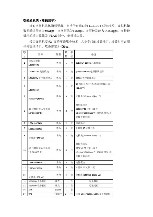
交换机系统(质保三年)
核心交换机具体指标要求:支持所有端口的L2/L3/L4线速转发,虚拟机箱数据通道带宽≥60Gbps,交换矩阵≥80Gbps,多层转发能力≥35Mpps,支持跨机箱的端口镜像及VLAN划分,单模模块等。
楼层交换机要求:支持环路堆叠技术,具备专门的堆叠端口,堆叠时不占用任何交换端口,堆叠带宽≥4Gbps。
三年7*24小时上门服务,终生7*24小时接电话技术支持,UPS整机一年(电池三年)
接到医院用户报修电话后,在2小时内响应,24小时内修复。
遇紧急维修时安排在1小时内上门
中标方须提供以上设备原厂授权,所提供产品序列号需与最终用户单位名称一致,外包装需指明最终用户单位名称,并负责全部设备的系统集成安装及维护。
OLT双上行配置参考A、双上行应用相关说明当OLT区分业务进行双边缘或多边缘组网时(典型应用:HSI业务接入BRAS,VOIP/IPTV等增值业务接入SR),也可分别创建两对或多对链路聚合组实现不同上行方向的组网保护。
OLT与上层设备之间存在2-8条上行链路,将这些链路做链路聚合,通过链路聚合实现部分上行链路中断后依然可保持业务正常。
上层设备的用户板软硬件相对复杂,建议聚合端口分布在不同的业务板上,提高组网可靠性,因此要求上层设备必须支持跨板聚合。
如果OLT存在两块上行业务板,建议聚合端口均匀分布在两块上行业务板;为降低组网成本,OLT也可只配置一块上行业务板。
OLT支持手工方式和LACP静态方式建立跨板聚合组,优先推荐静态LACP方式(需上层设备也支持),提升组网可靠性,防止单通等故障的发生。
故障检测和通告方式包括:物理链路状态、LACP协议。
如果OLT与上层设备之间通过光纤直连,则通过检测物理链路状态可实现快速倒换(50ms左右);如果OLT与上层设备之间通过传输设备相连,则必须采用L ACP协议进行故障检测和通告,倒换时间与LACP交互周期相关(1s~10s)。
B、数据配置①.城域网节点配置参考(模板华为S9306配置命令)[SCLES-MC-CMNET-SW01]lacp priority 100[SCLES-MC-CMNET-SW01]interface Eth-Trunk0[SCLES-MC-CMNET-SW01-Eth-Trunk0]mode lacp-static[SCLES-MC-CMNET-SW01]interface GigabitEthernet1/0/3[SCLES-MC-CMNET-SW01-GigabitEthernet1/0/3]eth-trunk 0[SCLES-MC-CMNET-SW01-GigabitEthernet1/0/3]lacp priority 100[SCLES-MC-CMNET-SW01]interface GigabitEthernet1/0/4[SCLES-MC-CMNET-SW01-GigabitEthernet1/0/4]eth-trunk 0[SCLES-MC-CMNET-SW01-GigabitEthernet1/0/4]lacp priority 100②华为OLT双上行链路聚合配置参考MA5680T(config)#link-aggregation 0/19 0 0/20 0 egress-ingress //不配置LACP协议MA5680T(config)#link-aggregation 0/19 0 0/20 0 egress-ingress workmod e lacp-static ////配置LACP协议③爱立信olt双上行配置操作步骤第一、删除上联板卡(g28板)上的所有端口,具体步骤如下:1)删除ap-0板上的端口gsx-0-1,需要先删除网管地址操作命令Edit pack ap-0 oosEdit port gsx-0-1 oosconfiginterface gsx-0-1no ip ifc vlan 4000 172.16.67.35 255.255.255.224exitremove port gsx-0-1delete port gsx-0-12)删除ap-0板上的端口gsx-0-b1,需要先删除olt上配置的所有交叉连接,此步骤比较繁琐,需要提前查看交叉链接,操作命令如下:Edit port olt-15-1 oosEdit port gsx-0-b1 oosDelete crs gem 256 olt-15-1 gsx-0-b1 add 1000Delete crs gem 257 olt-15-1 gsx-0-b1 add 1000Delete crs gem 258 olt-15-1 gsx-0-b1 add 1000Delete crs gem 259 olt-15-1 gsx-0-b1 add 1000(只列举了假设的4条)删除掉所有的交叉链接后执行Remove port gsx-0-b1Delete port gsx-0-b13)如果需要做上联的另一张板卡上有数据,执行类似以上的命令即可。
今天正在调试设备,突然发现vlan删不掉,提示我正在被占用。
这个vlan是 vlan 100解决办法:undo interface vlan 100undo vlan 100我想把5/0/15号端口改成access,但是不知道怎么搞定,谢谢大家了。
我是个华为的新手,第一次配置华为交换机。
interface GigabitEthernet5/0/15port link-type trunkport trunk allow-pass vlan 2 to 4094先执行undo port trunk allow-pass vlan 2 to 4094然后就可以通过port link-type access改啦一般undo后如果还提示需恢复到默认配置,基本都是没有允许vlan 1通过引起的。
很多人经常都是undo port trunk allow-pass vlan all ,结果连vlan 1也undo了。
所以还需要port trunk allow-pass vlan 1我想要执行这一步[SwitchA-Ethernet0/1]port link-type trunk但是提示的这个怎么解决?Error: Please renew the default configurations.什么意思啊?如何将S9306的某个端口类型从ACCESS改为trunk模式单位的交换机S9306两台当初是厂家调试的现在厂家也联系不上了最近买了一台海蜘蛛ISP版的想实现WEB认证和上网行为管理经了解需要在核心交换机上开启trunk才能让海蜘蛛读到局域网中的mac地址网络概况:光纤--防火墙172.16.254.3---核心交换机172.16.254.4---若干个VLAN现在想在不改变原有网络的基础上将核心交换机的GigabitEthernet1/0/0 改为trunk模式请问怎么操作谢谢大家配置如下:#sysname S9306-A#super password level 15 simple*****#vlan batch 38 40 to 110 911 1100#arp anti-attack gateway-duplicate enable #diffserv domain default#drop-profile default#vlan 38description to-S4196vlan 40description to-S5328-G1/0/6#interface Vlanif38description TO-firewallip address 172.16.254.4 255.255.255.0 #interface Vlanif40description TO-s5328-1ip address 172.16.40.252 255.255.255.0 #interface Vlanif41ip address 172.16.0.254 255.255.255.0 #interface Vlanif42ip address 172.16.1.252 255.255.255.0 #interface Vlanif43ip address 172.16.2.252 255.255.255.0 #interface Vlanif44ip address 172.1.3.252 255.255.255.0#interface Vlanif45ip address 172.16.4.252 255.255.255.0 #interface Vlanif46ip address 172.16.5.252 255.255.255.0 #interface Vlanif47ip address 172.16.6.252 255.255.255.0 #interface Vlanif48ip address 172.16.7.252 255.255.255.0 #interface Vlanif49ip address 172.16.8.252 255.255.255.0 #interface Vlanif50ip address 172.16.9.252 255.255.255.0 #interface Vlanif51ip address 172.16.10.252 255.255.255.0 #interface Vlanif52ip address 172.16.11.252 255.255.255.0 #interface Vlanif53ip address 172.16.12.252 255.255.255.0 #interface Vlanif54ip address 172.16.13.252 255.255.255.0 #interface Vlanif55ip address 172.16.14.252 255.255.255.0 #interface Vlanif56ip address 172.16.15.252 255.255.255.0 #interface Vlanif57ip address 172.16.16.252 255.255.255.0 #interface Vlanif58ip address 172.16.17.252 255.255.255.0 #interface Vlanif59ip address 172.16.18.252 255.255.255.0 #interface Vlanif60ip address 172.16.19.252 255.255.255.0 #interface Vlanif61ip address 172.16.20.252 255.255.255.0 #interface Vlanif62ip address 172.16.21.252 255.255.255.0 #interface Vlanif63ip address 172.16.22.252 255.255.255.0 #interface Vlanif64ip address 172.16.23.252 255.255.255.0 #interface Vlanif65ip address 172.16.24.252 255.255.255.0 #interface Vlanif66ip address 172.16.25.252 255.255.255.0 #interface Vlanif67ip address 172.16.26.252 255.255.255.0 #interface Vlanif68ip address 172.16.27.252 255.255.255.0 #interface Vlanif69ip address 172.16.28.252 255.255.255.0 #interface Vlanif70ip address 172.16.29.252 255.255.255.0 #interface Vlanif71ip address 172.16.30.252 255.255.255.0 #interface Vlanif72ip address 172.16.31.252 255.255.255.0 #interface Vlanif73ip address 172.16.32.252 255.255.255.0 #interface Vlanif74ip address 172.16.33.252 255.255.255.0 #interface Vlanif75ip address 172.16.34.252 255.255.255.0 #interface Vlanif76ip address 172.16.35.252 255.255.255.0 #interface Vlanif77ip address 172.16.36.252 255.255.255.0 #interface Vlanif78ip address 172.16.37.252 255.255.255.0#interface Vlanif79ip address 172.16.38.252 255.255.255.0#interface Vlanif80ip address 172.16.80.254 255.255.255.0vrrp vrid 80 virtual-ip 172.16.80.252vrrp vrid 80 priority 120vrrp vrid 80 preempt-mode timer delay 20vrrp vrid 80 track interface GigabitEthernet1/0/0 reduced 30 #interface Vlanif81ip address 172.16.81.254 255.255.255.0vrrp vrid 81 virtual-ip 172.16.81.252vrrp vrid 81 priority 120vrrp vrid 81 preempt-mode timer delay 20vrrp vrid 81 track interface GigabitEthernet1/0/0 reduced 30 #interface Vlanif82ip address 172.16.82.254 255.255.255.0vrrp vrid 82 virtual-ip 172.16.82.252vrrp vrid 82 priority 120vrrp vrid 82 preempt-mode timer delay 20vrrp vrid 82 track interface GigabitEthernet1/0/0 reduced 30 #interface Vlanif83ip address 172.16.83.254 255.255.255.0vrrp vrid 83 virtual-ip 172.16.83.252vrrp vrid 83 priority 120vrrp vrid 83 preempt-mode timer delay 20vrrp vrid 83 track interface GigabitEthernet1/0/0 reduced 30 #interface Vlanif84ip address 172.16.84.254 255.255.255.0vrrp vrid 84 virtual-ip 172.16.84.252vrrp vrid 84 priority 120vrrp vrid 84 preempt-mode timer delay 20vrrp vrid 84 track interface GigabitEthernet1/0/0 reduced 30 #interface Vlanif85ip address 172.16.85.254 255.255.255.0vrrp vrid 85 virtual-ip 172.16.85.252vrrp vrid 85 priority 120vrrp vrid 85 preempt-mode timer delay 20vrrp vrid 85 track interface GigabitEthernet1/0/0 reduced 30 #interface Vlanif86ip address 172.16.86.254 255.255.255.0vrrp vrid 86 virtual-ip 172.16.86.252vrrp vrid 86 priority 120vrrp vrid 86 preempt-mode timer delay 20vrrp vrid 86 track interface GigabitEthernet1/0/0 reduced 30 #interface Vlanif87ip address 172.16.87.254 255.255.255.0vrrp vrid 87 virtual-ip 172.16.87.252vrrp vrid 87 priority 120vrrp vrid 87 preempt-mode timer delay 20vrrp vrid 87 track interface GigabitEthernet1/0/0 reduced 30 #interface Vlanif88ip address 172.16.88.254 255.255.255.0vrrp vrid 88 virtual-ip 172.16.88.252vrrp vrid 88 priority 120vrrp vrid 88 preempt-mode timer delay 20vrrp vrid 88 track interface GigabitEthernet1/0/0 reduced 30 #interface Vlanif89ip address 172.16.89.254 255.255.255.0vrrp vrid 89 virtual-ip 172.16.89.252vrrp vrid 89 priority 120vrrp vrid 89 preempt-mode timer delay 20vrrp vrid 89 track interface GigabitEthernet1/0/0 reduced 30 #interface Vlanif90ip address 172.16.90.254 255.255.255.0vrrp vrid 90 virtual-ip 172.16.90.252vrrp vrid 90 priority 120vrrp vrid 90 preempt-mode timer delay 20vrrp vrid 90 track interface GigabitEthernet1/0/0 reduced 30 #interface Vlanif91ip address 172.16.91.254 255.255.255.0vrrp vrid 91 virtual-ip 172.16.91.252vrrp vrid 91 priority 120vrrp vrid 91 preempt-mode timer delay 20vrrp vrid 91 track interface GigabitEthernet1/0/0 reduced 30 #interface Vlanif92ip address 172.16.92.254 255.255.255.0vrrp vrid 92 virtual-ip 172.16.92.252vrrp vrid 92 priority 120vrrp vrid 92 preempt-mode timer delay 20vrrp vrid 92 track interface GigabitEthernet1/0/0 reduced 30 #interface Vlanif93ip address 172.16.93.254 255.255.255.0vrrp vrid 93 virtual-ip 172.16.93.252vrrp vrid 93 priority 120vrrp vrid 93 preempt-mode timer delay 20vrrp vrid 93 track interface GigabitEthernet1/0/0 reduced 30 #interface Vlanif94ip address 172.16.94.254 255.255.255.0vrrp vrid 94 virtual-ip 172.16.94.252vrrp vrid 94 priority 120vrrp vrid 94 preempt-mode timer delay 20vrrp vrid 94 track interface GigabitEthernet1/0/0 reduced 30 #interface Vlanif95ip address 172.16.95.254 255.255.255.0vrrp vrid 95 virtual-ip 172.16.95.252vrrp vrid 95 priority 120vrrp vrid 95 preempt-mode timer delay 20vrrp vrid 95 track interface GigabitEthernet1/0/0 reduced 30 #interface Vlanif96ip address 172.16.96.254 255.255.255.0vrrp vrid 96 virtual-ip 172.16.96.252vrrp vrid 96 priority 120vrrp vrid 96 preempt-mode timer delay 20vrrp vrid 96 track interface GigabitEthernet1/0/0 reduced 30 #interface Vlanif97ip address 172.16.97.254 255.255.255.0vrrp vrid 97 virtual-ip 172.16.97.252vrrp vrid 97 priority 120vrrp vrid 97 preempt-mode timer delay 20vrrp vrid 97 track interface GigabitEthernet1/0/0 reduced 30 #interface Vlanif98ip address 172.16.98.254 255.255.255.0vrrp vrid 98 virtual-ip 172.16.98.252vrrp vrid 98 priority 120vrrp vrid 98 preempt-mode timer delay 20vrrp vrid 98 track interface GigabitEthernet1/0/0 reduced 30#interface Vlanif99ip address 172.16.99.254 255.255.255.0vrrp vrid 99 virtual-ip 172.16.99.252vrrp vrid 99 priority 120vrrp vrid 99 preempt-mode timer delay 20vrrp vrid 99 track interface GigabitEthernet1/0/0 reduced 30 #interface Vlanif100ip address 172.16.100.254 255.255.255.0vrrp vrid 100 virtual-ip 172.16.100.252vrrp vrid 100 priority 120vrrp vrid 100 preempt-mode timer delay 20vrrp vrid 100 track interface GigabitEthernet1/0/0 reduced 30 #interface Vlanif101ip address 172.16.101.254 255.255.255.0vrrp vrid 101 virtual-ip 172.16.101.252vrrp vrid 101 priority 120vrrp vrid 101 preempt-mode timer delay 20vrrp vrid 101 track interface GigabitEthernet1/0/0 reduced 30 #interface Vlanif102ip address 172.16.102.254 255.255.255.0vrrp vrid 102 virtual-ip 172.16.102.252vrrp vrid 102 priority 120vrrp vrid 102 preempt-mode timer delay 20vrrp vrid 102 track interface GigabitEthernet1/0/0 reduced 30 #interface Vlanif103ip address 172.16.103.254 255.255.255.0vrrp vrid 103 virtual-ip 172.16.103.252vrrp vrid 103 priority 120vrrp vrid 103 preempt-mode timer delay 20vrrp vrid 103 track interface GigabitEthernet1/0/0 reduced 30 #interface Vlanif104ip address 172.16.104.254 255.255.255.0vrrp vrid 104 virtual-ip 172.16.104.252vrrp vrid 104 priority 120vrrp vrid 104 preempt-mode timer delay 20vrrp vrid 104 track interface GigabitEthernet1/0/0 reduced 30 #interface Vlanif105ip address 172.16.105.254 255.255.255.0vrrp vrid 105 virtual-ip 172.16.105.252vrrp vrid 105 priority 120vrrp vrid 105 preempt-mode timer delay 20vrrp vrid 105 track interface GigabitEthernet1/0/0 reduced 30 #interface Vlanif106ip address 172.16.106.254 255.255.255.0vrrp vrid 106 virtual-ip 172.16.106.252vrrp vrid 106 priority 120vrrp vrid 106 preempt-mode timer delay 20vrrp vrid 106 track interface GigabitEthernet1/0/0 reduced 30 #interface Vlanif107ip address 172.16.107.254 255.255.255.0vrrp vrid 107 virtual-ip 172.16.107.252vrrp vrid 107 priority 120vrrp vrid 107 preempt-mode timer delay 20vrrp vrid 107 track interface GigabitEthernet1/0/0 reduced 30 #interface Vlanif108ip address 172.16.108.254 255.255.255.0vrrp vrid 108 virtual-ip 172.16.108.252vrrp vrid 108 priority 120vrrp vrid 108 preempt-mode timer delay 20vrrp vrid 108 track interface GigabitEthernet1/0/0 reduced 30 #interface Vlanif109ip address 172.16.109.254 255.255.255.0vrrp vrid 109 virtual-ip 172.16.109.251vrrp vrid 109 virtual-ip 172.16.109.252vrrp vrid 109 priority 120vrrp vrid 109 preempt-mode timer delay 20vrrp vrid 109 track interface GigabitEthernet1/0/0 reduced 30 #interface Vlanif110ip address 172.16.110.254 255.255.255.0vrrp vrid 110 virtual-ip 172.16.110.252vrrp vrid 110 priority 120vrrp vrid 110 preempt-mode timer delay 20vrrp vrid 110 track interface GigabitEthernet1/0/0 reduced 30 #interface Ethernet0/0/0#interface GigabitEthernet1/0/0port link-type accessport default vlan 38#interface GigabitEthernet1/0/1description to-S5328-G1/0/6port link-type accessport default vlan 40#interface GigabitEthernet1/0/2port link-type accessport default vlan 41#interface GigabitEthernet1/0/3port link-type accessport default vlan 42#interface GigabitEthernet1/0/4 port link-type accessport default vlan 43#interface GigabitEthernet1/0/5 port link-type accessport default vlan 44#interface GigabitEthernet1/0/6 port link-type accessport default vlan 45#interface GigabitEthernet1/0/7 port link-type accessport default vlan 46#interface GigabitEthernet1/0/8 port link-type accessport default vlan 47#interface GigabitEthernet1/0/9 port link-type accessport default vlan 48#interface GigabitEthernet1/0/10 port link-type accessport default vlan 49#interface GigabitEthernet1/0/11 port link-type accessport default vlan 50#interface GigabitEthernet1/0/12 port link-type accessport default vlan 51#interface GigabitEthernet1/0/13 port link-type accessport default vlan 52#interface GigabitEthernet1/0/14 port link-type accessport default vlan 53#interface GigabitEthernet1/0/15 port link-type accessport default vlan 54#interface GigabitEthernet1/0/16 port link-type accessport default vlan 55#interface GigabitEthernet1/0/17 port link-type accessport default vlan 56#interface GigabitEthernet1/0/18 port link-type accessport default vlan 57#interface GigabitEthernet1/0/19 port link-type accessport default vlan 58#interface GigabitEthernet1/0/20port link-type accessport default vlan 59#interface GigabitEthernet1/0/21 port link-type accessport default vlan 60#interface GigabitEthernet1/0/22 port link-type accessport default vlan 61#interface GigabitEthernet1/0/23 port link-type accessport default vlan 62#interface GigabitEthernet1/0/24 port link-type accessport default vlan 63#interface GigabitEthernet1/0/25 port link-type accessport default vlan 64#interface GigabitEthernet1/0/26 port link-type accessport default vlan 65#interface GigabitEthernet1/0/27 port link-type accessport default vlan 66#interface GigabitEthernet1/0/28 port link-type accessport default vlan 67#interface GigabitEthernet1/0/29 port link-type accessport default vlan 68#interface GigabitEthernet1/0/30 port link-type accessport default vlan 69#interface GigabitEthernet1/0/31 port link-type accessport default vlan 70#interface GigabitEthernet1/0/32 port link-type accessport default vlan 71#interface GigabitEthernet1/0/33 port link-type accessport default vlan 72#interface GigabitEthernet1/0/34 port link-type accessport default vlan 73#interface GigabitEthernet1/0/35 port link-type accessport default vlan 74#interface GigabitEthernet1/0/36 port link-type accessport default vlan 75#interface GigabitEthernet1/0/37port link-type accessport default vlan 76#interface GigabitEthernet1/0/38 port link-type accessport default vlan 77#interface GigabitEthernet1/0/39 port link-type accessport default vlan 78#interface GigabitEthernet1/0/40 port link-type accessport default vlan 79#interface GigabitEthernet1/0/41 port link-type accessport default vlan 81#interface GigabitEthernet1/0/42 port link-type accessport default vlan 82#interface GigabitEthernet1/0/43 port link-type accessport default vlan 83#interface GigabitEthernet1/0/44 port link-type accessport default vlan 84#interface GigabitEthernet1/0/45 port link-type accessport default vlan 85#interface GigabitEthernet1/0/46 port link-type accessport default vlan 86#interface GigabitEthernet1/0/47 #interface GigabitEthernet2/0/0 port link-type accessport default vlan 110undo negotiation auto#interface GigabitEthernet2/0/1 port link-type accessport default vlan 87undo negotiation auto#interface GigabitEthernet2/0/2 port link-type accessport default vlan 88#interface GigabitEthernet2/0/3 port link-type accessport default vlan 89#interface GigabitEthernet2/0/4 port link-type accessport default vlan 90#interface GigabitEthernet2/0/5 port link-type accessport default vlan 91#interface GigabitEthernet2/0/6port link-type accessport default vlan 92#interface GigabitEthernet2/0/7 port link-type accessport default vlan 93#interface GigabitEthernet2/0/8 port link-type accessport default vlan 94#interface GigabitEthernet2/0/9 port link-type accessport default vlan 95#interface GigabitEthernet2/0/10 port link-type accessport default vlan 96#interface GigabitEthernet2/0/11 port link-type accessport default vlan 97#interface GigabitEthernet2/0/12 port link-type accessport default vlan 98#interface GigabitEthernet2/0/13 port link-type accessport default vlan 99#interface GigabitEthernet2/0/14 port link-type accessport default vlan 100#interface GigabitEthernet2/0/15 port link-type accessport default vlan 101#interface GigabitEthernet2/0/16 port link-type accessport default vlan 102#interface GigabitEthernet2/0/17 port link-type accessport default vlan 103#interface GigabitEthernet2/0/18 port link-type accessport default vlan 104#interface GigabitEthernet2/0/19 port link-type accessport default vlan 105#interface GigabitEthernet2/0/20 port link-type accessport default vlan 106#interface GigabitEthernet2/0/21 port link-type accessport default vlan 107#interface GigabitEthernet2/0/22 port link-type accessundo negotiation auto#interface GigabitEthernet2/0/23port link-type accessport default vlan 109#interface NULL0#aaaauthentication-scheme default#authorization-scheme default#accounting-scheme default#domain default##ip route-static 0.0.0.0 0.0.0.0 172.16.254.3ip route-static 172.16.150.0 255.255.255.0 172.16.110.251 ip route-static 172.16.151.0 255.255.255.0 172.16.110.251 ip route-static 172.16.180.0 255.255.255.0 172.16.87.251 ip route-static 172.16.200.0 255.255.255.0 172.16.40.251 ip route-static 172.16.201.0 255.255.255.0 172.16.40.251 ip route-static 172.16.202.0 255.255.255.0 172.16.40.251 ip route-static 172.16.203.0 255.255.255.0 172.16.40.251 ip route-static 172.16.204.0 255.255.255.0 172.16.40.251 ip route-static 172.16.205.0 255.255.255.0 172.16.40.251 ip route-static 172.16.206.0 255.255.255.0 172.16.40.251 ip route-static 172.16.207.0 255.255.255.0 172.16.40.251 ip route-static 172.16.208.0 255.255.255.0 172.16.40.251 ip route-static 172.16.209.0 255.255.255.0 172.16.40.251 ip route-static 172.16.210.0 255.255.255.0 172.16.40.251 ip route-static 172.16.211.0 255.255.255.0 172.16.40.251 ip route-static 172.16.212.0 255.255.255.0 172.16.40.251 ip route-static 172.16.213.0 255.255.255.0 172.16.40.251 ip route-static 172.16.214.0 255.255.255.0 172.16.40.251ip route-static 172.16.215.0 255.255.255.0 172.16.40.251 ip route-static 172.16.216.0 255.255.255.0 172.16.40.251 ip route-static 172.16.217.0 255.255.255.0 172.16.40.251 #user-interface con 0user-interface vty 0 4user privilege level 15set authentication password simple *******user-interface vty 16 20#return方案一port def vlan 1port link trunkport def vlan 1port link trunkkmyd 发表于2014-03-19 15:51:39谢谢这两步操作完后我是否需要再重新为这个端口添加IP地址和VLANinterface gigabitethernet 1/0/0port def vlan 1port link-type trunkport trunk allow-pass vlan 38sysinterface vlanif 38ipadress 172.16.254.4 255.255.255.0要先删除掉端口下原来的配置interface GigabitEthernet1/0/0undo port link-typeundo port default vlanport link-type trunkport trunk allow-pass vlan 38 40 to 110 911 1100。

S9300系列T比特核心路由交换机S9300系列是华为公司面向融合多业务的网络架构而推出的新一代高端智能T比特核心路由交换机。
该产品基于华为公司智能多层交换的技术理念,在提供稳定、可靠、安全的高性能L2/L3层交换服务基础上,实现高清视频流承载、大容量无线网络、弹性云计算、硬件IPv6、一体化安全等业务应用,同时具备强大扩展性和可靠性。
S9300系列交换机广泛适用于广域网、城域网、园区网络和数据中心,帮助企业构建面向应用的网络平台,提供交换路由一体化的端到端融合网络。
S9300系列提供S9303、S9306、S9312三种产品形态,支持不断扩展的交换能力和端口密度。
整个系列秉承模块通用化、部件归一化的设计理念,最小化备件成本,在保证设备扩展性的同时最大限度地保护用户投资。
此外,S9300作为新一代智能交换机,采用了多种绿色节能创新技术,在不断提升性能及稳定性的同时,大幅降低设备能源消耗,减小噪声污染,为网络绿色可持续发展提供领先的解决方案。
S9300系列交换机产品彩页S9300系列交换机产品彩页(简版)产品特点先进交换架构提升网络扩展性背板具备良好的扩展性,可平滑扩展至更高带宽,支持单端口速率40G、100G平滑升级,同时完美兼容现网板卡,保护初始投资。
超高万兆端口密度,单台设备最大可支持480个万兆端口,助力企业园区和数据中心迎来全万兆核心时代。
运营级高可靠性设计,保障企业应用永续运行9300具备超越5个9的运营级高可靠性,主控、电源、风扇等关键部件冗余设计,所有模块均支持热插拔。
支持ISSU业务无损升级,减少关键业务和服务中断。
CSS集群创新性采用交换网集群技术,克服了业界普遍采用的线卡集群跨框多次交换,交换效率低下的架构难题,提供业界主机间最大的256G 集群带宽,同时可以通过跨框链路聚合提高链路的利用率,并消除单点故障。
支持完善的运维检测与性能管理802.3ah、802.1ag和ITU-Y.1731,能够对网络传输中的时延、抖动等参数进行精确统计,实时监测网络运行情况,并在设备故障发生时快速定位。
一、FTP环境的搭建:(1)将S9300 设置为配置S9300 作为,假设Ethernet0/0/0 接口IP 地址为10、164、30、20,FTP 用户名为S9300,密码为123456,FTP 工作目录就是cfcard:/。
<Quidway> system-view[Quidway] enableInfo: Succeeded in starting the 、[Quidway] aaa[Quidway-aaa] local-user S9300 password cipher 123456info: A new user added[Quidway-aaa] local-user S9300 cfcard:[Quidway-aaa] local-user S9300 service-type ftp通常S9300 的各种配置文件都在CF 卡,所以FTP 工作目录一般都写为cfcard:/。
这个目录一定要正确填写,因为根目录无法改动。
升级前查询信息:1、查询当前软件版本display version2、检查设备运行状态display device display alarm all3、检查CF 卡中的剩余空间查瞧当前Master 主控板剩余空间dir cfcard:/查瞧当前slave 主控板剩余空间。
dir slave#cfcard:4、删除多余文件系统软件大包(以“、cc”结束),config文件(以“、cfg”或“、zip”结束)、License 文件(以“、dat”结束)、Web 文件(以“、web”结束)、补丁文件(以“、pat”结束)请在确认没有使用后再删除。
# 删除当前Master 主控板CF 卡上的多余文件。
<Quidway> delete cfcard:/vrpcfg1、zipDelete cfcard:/vrpcfg1、zip?[Y/N]:yInfo: Deleting 、# 删除当前Slave 主控板CF 卡上的多余文件。
网络改造工程新增汇聚交换机S9306业务割接方案(湖西)XX公司2015年3月10日文档信息变更记录术语和缩写为了方便阅读,特将文中提及的术语及缩写列示如下:第- 2 -页目录第一章工程概要 ............................................................................................................................... - 4 -第二章影响范围 ............................................................................................................................... - 5 -第三章人员组成 ............................................................................................................................... - 6 -3.1方案编制 (6)3.2参与人员 (6)3.3职责分工 (6)第四章网络结构 ............................................................................................................................... - 8 -4.1网络调整前现状描述 (8)4.2实施内容 (9)4.3网络调整后组网结构 (9)第五章准备工作 ............................................................................................................................. - 10 -5.1系统备份 (10)5.2链路测试 (10)5.3端口对应表 (10)第六章割接步骤 ..............................................................................................................................- 11 -6.1割接时间安排 (11)6.2实施步骤 (11)步骤一:打通S8016-2至S9306-1的互连链路................................................................. - 11 -步骤二:将S8016-1的端口链路逐一迁移至S9306-1..................................................... - 13 -步骤三:将S8016-2的端口链路逐一迁移至S9306-2..................................................... - 14 -第七章业务验证 ............................................................................................................................. - 16 -7.1割接后测试 .. (16)7.2保存配置 (16)第八章应急回退 ............................................................................................................................. - 17 -第- 3 -页第一章工程概要为优化DCN网络性能,增强其安全及稳定性,应集团网运要求,对广西电信承载网进行设备升级改造。
园区交换机配置模板下面以97机房9306为例一、配置系统名sysname SM-SY-XY-S9306-L3-1.MAN二、配置网管VLAN及其IP地址vlan 101qinterface Vlan-interface 101description WangGuanip address 172.16.96.12 255.255.255.0三、配置远程登陆时的本地用户及超级用户的用户名、密码user-interface vty 0 14authentication-mode aaaidle-timeout 15 0qaaalocal-user admin password cipher sm-adminlocal-user admin service-type telnetlocal-user admin level 1qsuper password level 3 cipher sm@770四、配置防病毒访问控制列表acl number 3000rule 1 deny tcp destination-port eq 135rule 2 deny tcp destination-port eq 136rule 3 deny tcp destination-port eq 137rule 4 deny tcp destination-port eq 138rule 5 deny tcp destination-port eq 139rule 6 deny udp destination-port eq 135rule 7 deny udp destination-port eq 136rule 8 deny udp destination-port eq netbios-nsrule 9 deny udp destination-port eq netbios-dgmrule 10 deny udp destination-port eq netbios-ssnrule 11 deny tcp destination-port eq 1434rule 12 deny udp destination-port eq 1434rule 13 deny tcp destination-port eq 445rule 14 deny udp destination-port eq 445五、配置网管地址及团体属性snmp-agent trap enable standardsnmp-agent trap enable basetrapsnmp-agent target-host trap address udp-domain 192.168.254.3 params securityname S9306snmp-agent community read S9306snmp-agent community write S/S9306snmp-agent sys-info version allntp-service unicast-server 192.168.254.22ntp-service unicast-server 192.168.254.21 preference六、配置默认路由ip route-static 0.0.0.0 0.0.0.0 172.16.96.1七、配置上行端口数据interface GigabitEthernet1/0/0description To-SM-SY-XY-SE800-A-1.MAN GE14/0/4------------对端口进行描述undo negotiation auto----------------------------------------------------强制千兆,全双工模式port link-type hybridport hybrid tagged vlan 102undo port hybrid vlan 1broadcast-suppression 10 -----------------------------------------------设置广播抑制八、灵活QinQ 以青山三村上连列东S9306为例SE800G 1/0/0S9306G 1/0/47S3552以vlan 205到214打上外标1001vlan 215到224打上外标1002interface GigabitEthernet1/0/47description To_QingShangShanChun_S3552 -------------对端口进行描述undo negotiation auto------------------------------------------强制千兆,全双工模式port link-type hybrid 端口类型为Hybridport hybrid tagged vlan 107 透传网管Vlan 107port hybrid untagged vlan 1001 to 1002 透传Vlan 1001和1002port vlan-stacking vlan 205 to 214 stack-vlan 1001 添加外层标签1001port vlan-stacking vlan 215 to 224 stack-vlan 1002 添加外层标签1002quit上行口透传interface GigabitEthernet1/0/0description To-SM-LD-5F-SE800-A-3.MAN GE2/0/3undo negotiation autoport link-type hybridport hybrid tagged vlan 1001 1002 107undo port hybrid vlan 1broadcast-suppression 10九、端口限速(城域网需要)acl number 3000rule 0 permit iptraffic classifier TC_2M_Rate operator andif-match acl 3000traffic classifier TC_4M_Rate operator andif-match acl 3000traffic classifier TC_6M_Rate operator andif-match acl 3000traffic classifier TC_8M_Rate operator andif-match acl 3000traffic classifier TC_10M_Rate operator andif-match acl 3000traffic classifier TC_20M_Rate operator andif-match acl 3000traffic classifier TC_30M_Rate operator andif-match acl 3000traffic behavior TB_1M_Ratecar cir 2048 pir 2048 cbs 16384 pbs 16384 green pass yellow pass red discardtraffic behavior TB_4M_Ratecar cir 4096 pir 4096 cbs 32768 pbs 32768 green pass yellow pass red discardtraffic behavior TB_6M_Ratecar cir 6144 pir 6144 cbs 49152 pbs 49152 green pass yellow pass red discardtraffic behavior TB_8M_Ratecar cir 8192 pir 8192 cbs 65536 pbs 65536 green pass yellow pass red discardtraffic behavior TB_10M_Ratecar cir 10240 pir 10240 cbs 81920 pbs 81920 green pass yellow pass red discardtraffic behavior TB_20M_Ratecar cir 20480 pir 20480 cbs 163840 ebs 163840 pir 20480 green pass yellow pass red discardtraffic behavior TB_30M_Ratecar cir 30720 pir 30720 cbs 245760 ebs 245760 pir 30720 green pass yellow pass red discard(注:cbs=8*cir 效果比较好)traffic policy QP_2M_Rateclassifier TC_2M_Rate behavior TB_2M_Ratetraffic policy QP_4M_Rateclassifier TC_4M_Rate behavior TB_4M_Ratetraffic policy QP_6M_Rateclassifier TC_6M_Rate behavior TB_6M_Ratetraffic policy QP_8M_Rateclassifier TC_8M_Rate behavior TB_8M_Ratetraffic policy QP_10M_Rateclassifier TC_10M_Rate behavior TB_10M_Rateqos policy QP_20M_Rateclassifier TC_20M_Rate behavior TB_20M_Rateqos policy QP_30M_Rateclassifier TC_30M_Rate behavior TB_30M_Rateinterface Ethernet 3/1/1port access vlan 1000description TO_LanYueLiang_WangBa_2Mtraffic-policy QP_2M_Rate inbound 入方向限速qos lr cir 2048 outbound 出方向限速interface Ethernet 3/1/1port access vlan 1000description TO_LanYueLiang_WangBa_4Mtraffic-policy QP_4M_Rate inbound 入方向限速qos lr cir 4096 outbound 出方向限速interface Ethernet 3/1/1port access vlan 1000description TO_LanYueLiang_WangBa_6Mtraffic-policy QP_6M_Rate inbound 入方向限速qos lr cir 6144 outbound 出方向限速interface Ethernet 3/1/1port access vlan 1000description TO_LanYueLiang_WangBa_10Mtraffic-policy QP_8M_Rate inbound 入方向限速qos lr cir 8192 outbound 出方向限速interface Ethernet 3/1/1port access vlan 1000description TO_LanYueLiang_WangBa_10Mtraffic-policy QP_10M_Rate inbound 入方向限速qos lr cir 10240 outbound 出方向限速interface Ethernet 3/1/1port access vlan 1000description TO_LanYueLiang_WangBa_20Mtraffic-policy QP_20M_Rate inbound 入方向限速qos lr cir 20480 outbound 出方向限速interface Ethernet 3/1/1port access vlan 1000description TO_LanYueLiang_WangBa_30Mtraffic-policy QP_30M_Rate inbound 入方向限速qos lr cir 30720 outbound 出方向限速。
一、配置管理接口、配置OLT的读写团体字、创建ems网管管理vlanvlan 49 standard //配置城域网管理vlanvlan 307 standard //配置承载网管理vlanport vlan 49 0/19 0 //配置vlan从上行口透传port vlan 307 0/19 1interface vlanif49 //配置私网地址ip address 60.173.116.26 255.255.255.0interface vlanif307 //配置私网地址ip address 10.28.158.121 255.255.255.0ip route-static 0.0.0.0 0.0.0.0 60.173.116.1 /增加默认路由ip route-static 10.0.0.0 255.0.0.0 10.28.158.1 /增加默认路由snmp-agent community read xxdx@eponsnmp-agent community write XXdx@gponsnmp-agent target-host trap-hostname XXdxepon address X.X.X.X udp-port 162trap-paramsname XXdxepon v1 securityname xxdx@ponsnmp-agent trap enable standard二、配置OLT的访问控制OLT设备R62配置了ACL规则的,通过packet filter在上行口引用,升级到R8版本后会导致不在ACL范围内的专线IP业务不通,如果客户使用ACL目的只是为了进行telnet访问控制限制, sysman ip-access telnet X.X.X.X(起始网段地址) X.X.X.X(结束网段地址)sysman ip-access telnet 61.132.246.0(例如) 61.132.246.255(例如)sysman firewall telnet enable注意:先允许ip-access再enable,按顺序执行。
目录第3章华为S9603配置规范 (1)3.1系统基本配置规范 (1)3.1.1设备名称配置 (1)3.1.2Banner配置 (1)3.1.3设备自身时间及NTP (2)3.1.3.1时区配置 (2)3.1.3.2NTP配置 (2)3.1.4VTY接口配置 (3)3.1.4.1连接数限制 (3)3.1.4.2空闲时间 (3)3.1.4.3访问控制列表 (4)3.1.4.4配置范例 (4)3.1.5AAA配置 (5)3.1.5.1概述 (5)3.1.5.2AAA配置 (5)3.1.5.3本地用户帐号 (7)3.2端口配置规范 (7)3.2.1Loopback地址配置 (7)3.2.2GE端口配置 (8)3.2.2.1GE用做上连接口 (8)3.2.2.2GE端口QINQ配置 (9)3.2.2.3FE端口QINQ配置 (9)3.2.2.4GE、FE端口专线配置 (10)3.3路由协议配置规范 (10)3.3.1静态路由配置 (10)3.3.1.1静态路由配置方式 (10)3.4用户策略配置 (11)3.4.1定义防病毒访问控制列表 (11)3.4.2QOS策略配置 (12)3.4.3用户限速配置 (13)3.5网管配置 (14)3.5.1SNMP管理代理配置 (14)3.5.1.1全局开启SNMP进程 (14)3.5.1.2RO Community值 (15)3.5.1.3RW Community值 (16)3.5.1.4SNMP访问控制列表 (16)3.5.2故障管理配置 (17)3.5.2.1SNMP TRAP信息内容 (17)3.5.2.2SNMP TRAP 服务器地址 (17)3.5.2.3SNMP TRAP消息源地址 (18)3.5.2.4SYSLOG服务器地址 (18)3.5.2.5SYSLOG信息级别 (18)3.5.2.6SYSLOG消息源地址 (18)3.5.2.7配置范例(参考) (19)第1章华为S9603配置规范1.1 系统基本配置规范1.1.1设备名称配置配置说明:规范设备命名,唯一性标识城域网中的每台设备,用于对城域网的每台设备进行区分,方便设备管理,提高可读性和可管理性。
规范要求:设备名称要求符合第二章中“IP城域网网络设备命名及链路描述规范”中规定。
配置规范:配置后立即生效,设备名称显示在配置命令行的左边。
配置注意细节:可以根据需要在.M后添加设备型号。
1.1.2Banner配置配置说明:统一Banner语言,以省网标准为主。
规范要求:城域网所有交换机配置统一的Banner信息,登陆时提示:WARNING!!! Authorised access only, all of your done will be recorded! disconnect IMMEDIATELY if you are not an authorised user!配置规范:配置验证:登陆路由器时应看到banner提示。
配置注意细节:Banner语言应起到提示和警告非授权访问者的作用,严禁在Banner中出现任何表示欢迎的字样。
1.1.3设备自身时间及NTPNTP实现网络设备时间同步功能,与时间有关的应用,例如Log信息,基于时间限制带宽等,都需要基于正确的时间。
1.1.3.1 时区配置配置说明:统一设备的时区配置。
规范要求:配置系统时区为GMT+8,北京时区。
配置规范:无。
1.1.3.2 NTP配置配置说明:使用NTP同步网络上所有设备的时间,保证网络设备得到正确的时间。
规范要求:配置主和备两组NTP服务器。
配置规范:配置验证:配置注意细节:无。
1.1.4VTY接口配置1.1.4.1 连接数限制配置说明:对同时远程登陆到设备上的session数进行限制,可以防止大量的session 连接占用过多系统资源,同时便于集中运维,保证故障期间的正常处理。
规范要求:配置BRAS路由器并发连接数限制为10个。
配置规范:无1.1.4.2 空闲时间配置说明:设置了Telnet超时功能,当空闲时间超过设定值后,Telnet线程断开,防止未被授权的人员在操作员离开后进行非法操作。
规范要求:对VTY登录超时设置进行配置,设置空闲时间为10分钟。
配置规范:华为设备默认超时时间即为10分钟,配置后也不会显示配置。
1.1.4.3 访问控制列表配置说明:限制Telnet登录网络的源地址,从而增强设备的安全性,最大限度防止非法登陆尝试。
规范要求:配置Telnet源地址限制,包含省公司地址段和最小化的地市网管中心维护IP网段。
Telnet访问控制列表条目从10开始,条目的间隔步长为10,在访问控制列表的最后显示配置一条deny any any语句。
配置规范(参考):无。
1.1.4.4 配置范例1.1.5AAA配置1.1.5.1 概述AAA使用Radius统一验证,全省统一大后台。
1.1.5.2 AAA配置配置说明:配置用户的认证方式配置用户的计费方式配置用户认证服务器地址及参数配置用户计费服务器地址及参数规范要求:认证方式采用radius 方式计费方式采用radius 方式认证及计费服务器的地址根据省公司统一安排情况设置设置Radius 密钥时要与省后台相关人员协商确定认证端口号根据各个地方的实际情况设置计费端口号根据各个地方的实际情况设置配置规范(参考):radius-server template system radius方案名称为system主备radius和源地址在一条命令中radius-server authentication 202.103.28.138 1645 source loopback 0 secondary radius-server accounting 202.103.28.138 1645 source loopback 0 secondary radius-server shared-key aaa8010undo radius-server user-name domain-includednas-ip 59.175.247.182 上报radius报文中的源地址,取用上行接口的互联IP先在aaa视图下配置authentication-scheme、authorization-scheme、accounting-schemeauthentication-scheme systemauthentication-mode radius localauthorization-scheme systemauthorization-mode if-authenticated localaccounting-scheme systemaccounting-mode 没有先radius后local,只有如下方式hwtacacs HWTACACS accountinglocal Local accountinglocal-hwtacacs Local HWTACACS accountinglocal-radius Local RADIUS accountingnone No accountingradius RADIUS accountingdomain systemaaa视图下domain systemauthentication login radius-scheme system local 配置认证方案为先radius,后localauthorization login radius-scheme system local 配置授权方案为先radius,后localaccounting login radius-scheme system local 配置计费方案为先radius,后localundo access-limitstate activeundo idle-cut配置验证:配置注意细节:无。
1.1.5.3 本地用户帐号配置说明:配置本地用户帐号,作为AAA服务器连接失败时的应急登陆用。
规范要求:全省网络设备配置相同本地用户帐号admin,设置最高权限,使用省公司统一指定的密码,根据实际情况可保留地市本地管理帐号。
配置规范(参考):保留地市本地帐号。
1.2 端口配置规范1.2.1Loopback地址配置配置说明:配置Loopback地址,提供一个永远up的IP地址,用于各种路由协议邻居的建立、远程登录、设备管理等。
规范要求:城域骨干网交换机配置一个loopback 0地址,掩码必须为32位。
Loopback接口需添加端口描述,端口描述要求符合第二章中IP城域网网络设备命名及链路描述规范中规定。
配置规范:配置验证:无1.2.2GE端口配置1.2.2.1 GE用做上连接口配置说明:配置GE端口用做上连接口。
规范要求:配置GE端口speed 设置为1000M,双工为自行协商,并且在端口上定义病毒过滤策略。
配置接口描述符合第二章中IP城域网网络设备命名及链路描述规范中规定。
并注意端口描述中的对端端口应区别不同设备。
配置规范:无。
1.2.2.2 GE端口QINQ配置配置说明:配置GE端口用做下联接口,开启QINQ功能。
规范要求:配置开启GE端口QINQ功能。
配置接口描述符合第二章中IP城域网网络设备命名及链路描述规范中规定。
并注意端口描述中的对端端口应区别不同设备。
配置规范:无。
1.2.2.3 FE端口QINQ配置配置说明:配置FE端口做下联端口,开启QINQ功能。
规范要求:配置开启GE端口QINQ功能。
配置接口描述符合第二章中IP城域网网络设备命名及链路描述规范中规定。
配置规范:无。
1.2.2.4 GE、FE端口专线配置配置说明:配置接入专线用户的GE、FE端口。
规范要求:配置限速策略。
配置规范:无。
1.3 路由协议配置规范1.3.1静态路由配置1.3.1.1 静态路由配置方式配置说明:手工配置静态路由并设定相关参数。
规范要求:无。
配置规范:静态路由缺省优先级为60。
1.4 用户策略配置1.4.1定义防病毒访问控制列表配置说明:定义防病毒ACL,防御病毒攻击。
规范要求:定义周知及常见的病毒端口。
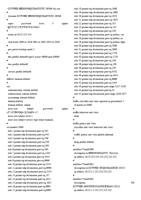
配置规范:acl number 3100 病毒端口过滤控制列表rule 0 deny tcp destination-port eq 3127rule 1 deny tcp destination-port eq 1025rule 2 deny tcp destination-port eq 5554rule 3 deny tcp destination-port eq 9996rule 4 deny tcp destination-port eq 1068rule 5 deny tcp destination-port eq 135rule 6 deny udp destination-port eq 135rule 7 deny tcp destination-port eq 137rule 8 deny udp destination-port eq netbios-nsrule 9 deny tcp destination-port eq 138rule 10 deny udp destination-port eq netbios-dgm rule 11 deny tcp destination-port eq 139rule 12 deny udp destination-port eq netbios-ssnrule 13 deny tcp destination-port eq 593rule 14 deny tcp destination-port eq 4444rule 15 deny tcp destination-port eq 5800rule 16 deny tcp destination-port eq 5900rule 17 deny tcp destination-port eq 8998rule 18 deny tcp destination-port eq 445rule 19 deny udp destination-port eq 445rule 20 deny udp destination-port eq 1434rule 21 deny udp destination-port eq 1433rule 22 deny tcp destination-port eq 707无1.4.2QOS策略配置配置说明:定义流类型,比如病毒端口过滤、QINGQ流(定义匹配用户VLAN范围)、网管入方向流及网管出方向流。