2012年美国MPIF标准35(粉末冶金结构零件材料标准)
- 格式:pdf
- 大小:13.01 MB
- 文档页数:92
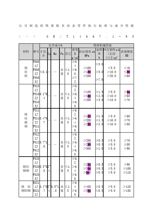
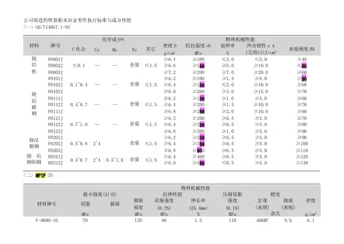
公司制造的铁基粉末冶金零件执行标准与成分性能<一>G B/T14667.1-9 3烧结铁和烧结碳钢的化学成分(%).材料牌号Fe CF-0000 97.7-100 0.0-0.3 F-0005 97.4-99.7 0.3-0.6 F-0008 97.1-99.4 0.6-0.9 注: 用差减法求出的其它元素(包括为了特殊目的而添加的其它元素)总量的最大值为2.0%。
▲注: 用差减法求出的其它元素(包括为了特殊目的而添加的其它元素)总量烧结铁-铜合金和烧结铜钢的化学成分(%).材料牌号Fe Cu CFC-020083.8-98.51.5-3.90.0-0.3FC-020593.5-98.21.5-3.90.3-0.6FC-020893.2-97.91.5-3.90.6-0.9FC-050591.4-95.74.0-6.0.3-0.6FC-050891.1-95.44.0-6.0.6-0.9烧结铁-镍合金和烧结镍钢的化学成材料牌号Fe Ni CuFN-0200 92.2-99.0 1.0-3.0 0.0-2.5FN-0205 91.9-98.7 1.0-3.0 0.0-2.5FN-0208 91.6-98.4 1.0-3.0 0.0-2.5FN-0405 89.9-96.7 3.0-5.5 0.2-2.0FN-0408 89.6-96.4 3.0-5.5 0.0-2.0注: 用差减法求出的其它元素(包括殊目的而添加的其它元素)总量的最2.0%的最大值为2.0%。
FC-0808 88.1-92.47.0-9.0.6-0.9FC-10 00 87.2-90.59.5-10.50.0-0.3⊙ 铁-铜合金和铜钢粉末冶金材料性能(MPIF-35)材料编号最小强度(A)(E)拉伸性能横向断裂压缩屈服强度(0.1%)硬度密度屈服极限极限强度屈服强度(0.2%)伸长率(25.4mm)宏观(表现)微观(换算的) MPa MPa MPa % MPa MPa 络氏g/cm3FC-0200-15-18-21-24 100 170 140 1.0 310 12011HRBN/A6.0 120 190 160 1.5 350140 18 6.3 140 210 180 1.5 390 160 26 6.6 170 230 200 2.0 430 180 36 6.9FC-0205-30-35-40-45 210 240 240 < 1.0 410 34037HRBN/A6.0 240 280 280 < 1.0 520 370 48 6.3 280 340 310 < 1.0 660 390 60 6.7 310 410 340 < 1.0 790 410 727.1FC-0205-60HT-70HT-80HT-90HT 410 480 < 0.5 660 39019HRC58HRC 6.2 480 550< 0.5 760 490 25 58 6.5 550620 (D) < 0.5 830 590 31 58 6.8 620 690 < 0.5 930 660 36 58 7.0FC-0208-30-40-50-60 210 240 240 < 1.0 410 39050HRBN/A5.8 280 340 310 < 1.0 620 430 616.3 340 410 380 < 1.0 860 460 73 6.7 410 520 450< 1.0 1070 490 847.2FC-0208-50HT-65HT-80HT-95HT 340 450< 0.5 660 40020HRC60HRC 6.1 450520 < 0.5 760 500 27 60 6.4 550620 (D) < 0.5 900 630 35 60 6.8 660 660 720 < 0.5 1030 720 43 60 7.1FC-0505-30-40-50210 300 250< 0.5 530 34051HRBN/A5.8 280 400 320 < 0.5 700 370 626.3 340 490 390 < 1.0 850400 72 6.7⊙<三>"DIN V 30 910" 及"ISO5755" (成分与性能略)< 规格二- 不锈钢>TypeChemical Composition (%)Physical MechanicalPropertiesFeCrNiCuTin Si Mn Mo C S OtherDensity(g/cm3)UltimateTensileStrength(kg/mm2)Elong-ation(%)Hard-nessSUS303LSC bal18.212.52.1.0 0.8 0.13 –< 0.080.2< 1.0 > 6.320Min.Min.2.RB4SUS316LSC bal17.13.52.1.00.750.12 2.2 < 0.080.01< 1.0 > 6.325Min.Min.5.RB38SUS410L bal 12.7–––0.8 0.18 –< 0.080.01< 1.0 > 6.320Min.Min.2.RB8。
MPIF Standard 35 is issued to provide the design and materials engineer with the information necessary for specifying powder metallurgy (PM) materials that have been developed by the PM parts manufacturing industry. This section of Standard 35 deals with conventional PM materials for structural parts. It does not apply to materials for PM self-lubricating bearings, powder forged (PF) or metal injection molded (MIM) products which are covered in separate editions of MPIF Standard 35. The same materials may appear in more than one section of the standard depending upon their common use, e.g., some structural materials may also be used in bearing applications and vice versa. Each section of this standard is divided into subsections based on the various types of PM materials in common commercial use within that section. Notes at the beginning of each subsection discuss the characteristics of that material. Users of this standard should make a determination as to the availability of any referenced material.The use of any MPIF Standard is entirely voluntary. MPIF Standards are issued and adopted in the public interest. They aredesigned to eliminate misunderstandings between the manufacturer and the purchaser and to assist the purchaser in selecting and obtaining the proper material for a particular product. Existence of MPIF Standards does not in any respect preclude any member or non-member of MPIF from manufacturing or selling products that use materials or testing procedures not included in MPIF Standards. Other such materials may be commercially available.By publication of these Standards, no position is taken with respect to the validity of any patent rights nor does MPIF undertake to ensure anyone utilizing the Standards against liability for infringement of any Letters Patent or accept any such liability.Neither MPIF nor any of its members assumes or accepts any liability resulting from use or non-use of any MPIF Standard. In addition, MPIF does not accept any liability or responsibility for the compliance of any product with any standard, the achievement of any minimum or typical values by any supplier, or for the results of any testing or other procedure undertaken in accordance with any Standard.MPIF Standards are subject to periodic review and may be revised. Users are cautioned to refer to the latest edition. New, approved materials and property data may be posted periodically on the MPIF website. Between published editions, go to to access data that will appear in the next printed edition of this standard.Both the purchaser and the manufacturer should, in order to avoid possible misconceptions or misunderstandings, agree on the following conditions prior to the manufacture of a PM part: minimum strength value, grade selection, chemical composition and alloying method, proof testing, typical property values and processes, that may affect the part application.ScopeNo part of this publication may be repro-duced, stored in a retrieval system, or transmitted, in any form or by any means, electronic, mechanical, photocopying, recording or otherwise, without the prior permission of the publisher.® Copyright 2012ISBN No. 978-0-9853397-1-5Published by Metal Powder Industries Federation105 College Road East Princeton, New Jersey 08540-6692 U.S.A.Tel: (609) 452-7700Fax: (609) 987-8523 E-mail: info@ Website: No part of this publication may be reproduced, stored in a retrieval system, or transmitted, in any form or by anymeans, electronic, mechanical, photocopying, recording or otherwise, without the prior permission of the publisher.2MPIF Standard 35 - 2012Materials Standards for PM Structural Parts Explanatory Notes and DefinitionsMinimum Value ConceptThe Metal Powder Industries Federation has adopted the concept of minimum strength values for PM materials for use in a structural application. These strength values may be used in designing for a PM part application. It should be noted that the powder metallurgy process offers equivalent minimum tensile strength values over a wide range of materials. It is seen as an advantage of the process that equivalent strengths can be developed by varying chemical composition, particle configuration, density and/or processing techniques.As an aid to the user in selecting materials, in addition to minimum strength values, typical values for other properties are listed. This makes it possible for the user to select and specify the exact PM material and properties most suitable for a specific application. The data provided define values for listed materials and display typical mechanical properties achieved under commercial manufacturing procedures. Physical and mechanical property performance characteristics may be changed by the use of processing steps beyond those designated in this standard. To select a material optimum in both properties and cost-effectiveness, it is essential that the part application be discussed with the PM parts manufacturer.Minimum ValueFor structural PM materials in the as-sintered condition the minimum value is expressed in terms of the yield strength (0.2% offset method) in thousand pounds per square inch (103 psi) or megapascals (MPa).For structural PM materials in the heat treated condition (quenched-hardened and sinter-hardened), the minimum value expressed is ultimate tensile strength in thousand pounds per square inch (103 psi) or megapascals (MPa). When PM materials are heat treated, tensile properties and hardness increase; nevertheless, the failure mode is such that 0.2% offset yield points are not always attainable. The yield and ultimate tensile strengths are therefore approximately the same for heat treated materials. (See Heat Treatment and Sinter Hardening page 4).For soft-magnetic materials the maximum value is expressed in terms of the coercive field strength in oersteds x 10.The tensile properties utilized for establishing this Standard were obtained from tensile specimens prepared specifically for evaluating PM materials. Tensile properties of specimens machined from commercial parts may vary from those obtained from individual specimens prepared specifically for evaluating PM materials.(See MPIF Standard 10for additional details on tensile test specimens.) What "Minimum Value" Means WhenSpecifying a PM MaterialThe recommended method of demonstrating minimum strength values is through the use of a static or dynamic proof test (see Proof Testing page 7) by the manufacturer and the purchaser using the first production lot of parts and a mutually agreed upon method of stressing the part. For example, from the design of a given part, it is agreed that the breaking load should be greater than a given force. If that force is exceeded in proof tests, the minimum strength is demonstrated. The first lot of parts can also be tested in service and demonstrated to be acceptable. The static or dynamic load to fracture is determined separately and these data are analyzed statistically to determine a minimum breaking force for future production lots. Exceeding that minimum force on future lots is proof that the specified strength has been met.Acceptable strength can also be demonstrated on tensile or transverse rupture test specimens. These should be of the same lot of material, have the same density as the parts themselves and should be sintered and heat treated along with the production parts. This method becomes less reliable when the parts are much larger than the test specimens. If transverse rupture test specimens are selected as the evaluating medium, manufacturer and purchaser must agree on minimum values because these may be lower than the typical values shown in the tables of data.The least desirable method for demonstrating a minimum property is to machine a test specimen from the part itself. This is particularly difficult with small or heat treated parts.If this method is to be used, manufacturer and purchaser must agree on the location from which the test specimen will be removed. This is necessary because density and strength can vary from point to point in a complex PM multi-level part. The tensile data reported in this specification for as-sintered materials are based on 0.250 inch (6.35 mm) thick as-pressed specimens per Figure 1 in MPIF Standard 10. For hardened (quench-hardened and sinter-hardened) specimens, the tensile data are based on a 0.190 inch (4.83 mm) diameter gauge section per Figure 4 in MPIF Standard 10. The gauge length is 1.0 inch (25.4 mm) in both instances. If other sizes are used, it must be demonstrated separately that equivalent results are obtained.Utilization of MPIF Standard 35 to specify a PM material means that unless the purchaser and manufacturer have agreed otherwise, the material will have the minimum value specified in the Standard. It is understood that if a test specimen is used to determine this value it shall have the dimensions and other3 33MPIF Standard 35, PM Structural Parts — 2012 Editioncharacteristics determinedby the manufacturer and prepared specifically for evaluating such material under conditions equivalent to those used in the manufacture of the part.(See Material Properties beginning on page 12.)Typical Values For each PM material listed, a set of typical values is shown for properties in addition to strength, e.g., density, hardness, elongation, etc., some or all of which may be important for a specific application. Typical values at the densities shown were determined by interpolation and extrapolation of graphs of average mechanical properties versus density. The mechanical property data were derived from interlaboratory studies for the sintering and heat treating of test bars under commercial conditions. The typical values are listed for general guidance only. They should not be considered minimum values. While achievable through normal manufacturing processing, they may vary somewhat depending upon the area of the component chosen for evaluation, or the specific manufacturing process utilized. Those properties listed under the "typical valuesection" for each material which are required by the purchaser should be discussed thoroughly with the PM parts manufacturer before establishing the specification. Required property values, other than those expressed as minimum, should be separately specified for each PM part, based on its intended use. Chemical Composition The chemical composition table for each material lists the principal elements by minimum and maximum mass percentage. "Other elements" include the total other elements and is reported as a maximum percentage. These may include other minor elements added for specific purposes. The chemical composition table for each material specifies the basic material before any oil impregnation, resin impregnation, steam treating or other such process has taken place. Mechanical Properties Mechanical property data indicate the minimum and typical properties that may be expected from test specimens conforming to the density and chemical composition criteria listed. It should be understood that mechanical properties used in this Standard were derived from test specimens prepared specifically for material evaluation and sintered under commercial production conditions. The impact energy (unnotched Charpy) and transverse rupture strength data were derived from standard test specimens designed for this purpose. (See MPIF Standards 40 and 41 for additional details.) Hardness values of heat-treated specimens are given first as apparent hardness and second, when available, as microindentation hardness values. Microindentation hardness values shown as Rockwell C were converted from 100 g load (0.981 N) Knoop microindentation hardness measurements. (See MPIF Standard 51.)Heat TreatmentFerrous PM parts containing 0.3% or higher combined carbon can be quench-hardened and tempered for increased strength, hardness and wear resistance. The percentages of carbon and other alloying elements effectively combined in the material and its density, determine the degree of hardening possible for any given quench condition. Microindentation hardness values of 650 HK 100 g (56 HRC) and higher can be obtained by quench hardening. The recommended procedure for heat treatment and/ or carburization of ferrous PM parts is with a gas type atmosphere or vacuum. The use of liquid salts is not recommended because of the possibility of surface absorption and subsequent bleed-out of the salts and internal corrosion. Low density parts may carburize throughout while higher density parts (7.0 g/cm 3 or higher) may develop a carburized case. Process control is necessary to ensure that specified carbon levels are maintained.(See MPIF Standard 52 for additional details.) Tempering or stress relief is required after quenching for maximum strength and durability; typically one (1) hour at temperature per 1 inch (25 mm) of section thickness. A compromise between hardness and such properties as impact energy is necessary because the tempering temperature to achieve surface hardness will not necessarily provide optimum strength properties. The tempering temperature is a major factor in determining final hardness.Sinter Hardening Some PM materials may, in effect, be quench hardened during the cooling cycle following sintering; this is known as sinter hardening. This is especially the case with prealloyed nickel-molybdenum-manganese and molyb-denum-chromium-manganese steels containing admixed copper. It is also true for martensitic stainless steels. Tempering or stress relief after hardening is required for maximum strength and durability.Surface Finish The overall finish and surface reflectivity of PM materials depends on density, tool condition and secondary operations. Conventional profilometer readings give an erroneous impression of surface finish because a different surface condition exists from that found on the machined or ground surfaces of wrought materials. Conventional readings take into account the peaks and valleys of machined surfaces, while PM parts have a series of very smooth surfaces that are interrupted with varying sized pores. Effective surface smoothness of PM components compares favorably with ground or ground and polished surfaces of wrought and cast components. Surface finish can be improved further by secondary operations such as repressing, honing, burnishing or4MPIF Standard 35, PM Structural Parts — 2012 Editiongrinding. The surface finish requirements and methods of determination must be established by mutual agreement between purchaser and producer, considering end use of the part. (See MPIF Standard 58 for additional details.)MicrostructureThe examination of the microstructure of a PM part can serve as a diagnostic tool and reveal the degree of sintering and other metallurgical information critical to the powder metallurgy process. There are several observations common to most sintered materials, as described briefly below. Comments on specific materials will be found in the subsections devoted to those particular materials.In selecting a section of a PM part for microstructural analysis, an interior plane, parallel to the pressing direction is preferred for mounting and polishing. Coarse and fine polishing should be continued until all of the pores are opened to view and the area fraction of porosity represents the density of the part. For example, an 80% dense part should show 20% of its area as pores. (See MPIF Standard 69 for additional details.) Parts with interconnected porosity can be impregnated with liquid epoxy during preparation of the specimen for microstructural examination. This will help prevent distortion of the voids during grinding or polishing.Sintered parts are always examined first in the unetched condition. In an average sinter there will be very few or no original particle boundaries seen at 200X. The more rounded the pores, the higher the strength, ductility and impact resistance.For mixes of iron and carbon with low nickel and copper content, the approximate carbon content can be estimated by the area fraction of pearlite. For an iron-copper carbon alloy with less than 5% copper, one hundred percent pearlite corresponds to approximately 0.8% combined carbon. Lesser amounts of pearlite mean proportionally less carbon. In nickel steels, even with only 2 to 4% by mass of nickel, the nickel-rich areas occupy a substantial area fraction. These should be discounted in estimating the area fraction of pearlite. The nickel-rich areas should not be confused with ferrite. Loss of surface carbon is generally to be avoided due to lower hardness and wear resistance. If a part is to have 0.6-0.9% carbon, decarburization is indicated if a surface layer measures less than 0.6% carbon. Minor amounts of surface decarburization are seldom a problem but if the layer is deeper than 0.010 inch (0.25 mm) it may be necessary to prove that function has not been impaired. (See ASTM E1077 for measuring the depth of decarburization.)Heat-treated ferrous parts generally show a mixture of martensite and fine pearlite. This is particularly true for the PM nickel and carbon steels that are of low hardenability. The maximum tensile strength for these materials has been found to occur in parts with 10% to 35% fine pearlite. The prealloyed steels usually showall martensite because of their greater hardenability.The formation of a carbide network embrittles the martensite in a hardened part and is generally to be avoided. Minor amounts of carbide in the outer 0.005inch (0.13 mm) of parts usually cause no problem.Minor amounts of retained austenite toughen the martensitic structure and usually cause no problem. Higher percentages are generally avoided because retained austenite can transform to brittle martensite in service.In preparing PM specimens for microstructural examination, the following etchants and procedures are recommended. Ferrous parts containing carbon are generally etched in 2% nital or a combination ofnital/picral. Austenitic stainless steel may be etched in glyceregia (10 mL HNO3,20 mL HCI, 30 mL glycerine)by swabbing for one to two minutes. Discard the solution after 30 minutes. Marble's reagent may also beused (10 grams Cu2S04, 50 mL HCI, 50 mL H20). Swab5 to 60 seconds. To develop grain boundaries in smallgrain clusters in bronze, etch by swabbing for 10 to 20 seconds in a mixture of 2 grams of K2Cr2O7, 4 mL of concentrated NaCI solution, 8 mL of H2SO4, 100 mL ofH2O. To develop a red color in copper-rich regions in bronze, etch by swabbing 10 to 20 seconds in 4%FeCI3 and H2O. For etching brasses, swab for 20 seconds in a solution of 5 mL of NH4OH, three drops ofH2O2, 5 mL of H20. This solution is unstable and shouldbe replaced after 20 minutes of usage. The K2Cr2O7 solution may also be used on nickel silver.PM Material Code DesignationThe PM material code designation or identifying codein the case of structural PM parts defines a specific material as to chemical composition and minimum strength expressed in 103psi. For example, FC-0208-60 is a PM copper steel material containing nominally 2% copper and 0.8% combined carbon possessing a minimum yield strength of 60 X 103 psi (60,000 psi) (410 MPa) in the as-sintered condition.A coding system offers a convenient means for designating both the chemical composition and minimum strength value of any standard PM material. Itis based on the system established by the industry withthe addition of a two-or three-digit suffix representing minimum strength in place of a suffix letter indicating density range. The density is given for each standard material as one of the typical values.Code designations in this Standard and revisions thereof apply only to PM materials for which MPIF Standards have been adopted. In order to avoid confusion, the MPIF coding system is intended for useonly with such materials and should not be used tocreate non-standard materials. The explanatory notes, property values, and other contents of this Standardhave no application to any other materials.In the coding system, the prefix letters denote the generaltype of material. For example, the prefix "CT" represents copper (C) and tin (T) which is known as bronze.556MPIF Standard 35, PM Structural Parts — 2012 EditionPrefix Letter CodeA Aluminum FS Iron SiliconC CopperFX Copper-Infiltrated Ironor SteelCT BronzeFY Iron Phosphorus CNZ Nickel-Silver G Free graphite CZ Brass M Manganese F IronN Nickel FCIron-Copper or Copper SteelP Lead FD Diffusion-AlloyedSteelS Silicon FF Soft-Magnetic Iron SS Stainless Steel FL Prealloyed Ferrousmaterial except Stainless SteelT (prealloyed) Tin FLD Diffusion-Alloyed Steel(prealloyed base)U Sulfur FN Iron-Nickel or NickelSteelY ZPhosphorus ZincPrefix and Numeric CodeThe numeric code following the prefix letter code refers to the composition of the material.In nonferrous materials, the first two numbers in the numeric code designate the percentage of the major alloying constituent. The last two numbers of the numeric code designate the percentage of the minor alloying constituent.For improved machinability lead is sometimes the third alloying element in a nonferrous alloy system. Lead will only be indicated by the letter "P" in the prefix. The percentage of lead or any other minor alloying element that is excluded from the numeric code is represented in the "Chemical Composition" that appears with each standard material.Illustration of PM nonferrous material designation coding:In ferrous materials, the major alloying elements (except combined carbon) are included in the prefix letter code. Other elements are excluded from the code but are represented in the "Chemical Composition" that appears with each Standard material. The first two digits of the numeric code indicate the percentage of the major alloying constituent present.Combined carbon content in ferrous materials is designated by the last two digits in the numeric code. The individual chemical composition tables show limits of carbon content for each alloy.The range of carbon that is metallurgically combined is indicated by the coding system. The combined carbon level can be estimated metallographically for sintered PM steels that have a well-defined ferrite/pearlite microstructure. For compositions with very low allowable carbon levels (< 0.08 %) total carbon determined analytically (ASTM E1019) is the recommended method.NOTE: When a clear pearlite to ferrite ratio cannot be determined metallographically, such as with heat treated steels and materials made from prealloyed base powders or diffusion-alloyed powders, then determination of combined carbon by normal metallographic methods is not practical. It is recommended that the carbon content of these materials should be reported as total carbon using the combustion method (ASTM E1019). The test method used should be identified in the report and identified as metallurgically combined carbon or total carbon. While total carbon will approximate the combined carbon in many materials, free graphite and other carbonaceous material will raise the total carbon content above the level of combined carbon, possibly causing the total carbon content to exceed the combined carbon level specified for the material.Illustration of PM ferrous material designation coding:In the case of PM stainless steels and PM prealloyedlow-alloy steels, the numeric code is replaced with a designation derived from modifications of the American Iron and Steel Institute alloy coding system, e.g., SS-316L-15, FL-4605-100HT.When a prealloyed steel powder is modified with elemental additions to create a hybrid low-alloy steel or a sinter-hardened steel, an alpha-numeric designator is used, e.g. FLN-4205-40, FLN2-4405-120HT or FLN4C-4005-60. If the base prealloyed composition has been modified (slight change to increase or decrease one or two elements) then a numeric designator will be added to the material designation code immediately after the first two digits for the prealloyed grade, e.g., FLC-48108-50HT.As with other PM materials, the suffix number denotes the specified minimum strength valueexpressed in 103psi.In the case of soft-magnetic alloys, the phosphorus containing irons are treated differently, since the amount of phosphorus is usually less than 1%. To indicate more accurately the nominal amount of phosphorus the code takes the nominal percent phosphorus, multiplies by 100 and uses this number for the first two digits in the code. The last two digits remain "00" since no carbon is required. For example, the iron-0.45% phosphorus alloy would be designated as: FY-4500.Suffix Digit CodeThe two- or three-digit suffix represents the minimumstrength value, expressed in 103psi, that the user can expect from the PM material possessing that chemical composition. In the as-sintered condition the strength is tensile yield; in the heat treated condition, it is ultimate tensile. (See Minimum Value page 3.) 67MPIF Standard 35, PM Structural Parts — 2012 EditionExamples of PM Material Designation CodingNominal Compositions Complete Code for Material, Composition Material by Percent & Minimum Strength (103psi) PM Bronze Cu-90, Sn-10 CT-1000-13 PM Nickel-Silver Cu-64, Ni-18, Zn-18 CNZ-1818-17 PM Nickel-Silver Cu-64, Ni-18, Zn-16, Pb-2 CNZP-1816-13 PM Brass Cu-90, Zn-10 CZ-1000-11PM Brass Cu-78, Zn-20, Pb-2 CZP-2002-12As-sintered Heat Treated PM Iron Fe, 99, C-0.2 F-0000-20 — PM Steel Fe, 98, C-0.8 F-0008-35 F-0008-85HT PM Copper Steel Fe, 96, Cu-2, C-0.8 FC-0208-60 FC-0208-95HT PM Nickel Steel Fe, 96, Ni-2, C-0.5 FN-0205-35 FN-0205-180HT PM Infiltrated Iron Fe, 78, Cu-20 FX-2000-25 — PM Infiltrated Steel Fe, 77, Cu-20, C-0.8 FX-2008-60 FX-2008-90HT PM Phosphorus Iron Fe, P-0.45 FY-4500-20W PM Stainless Steel (austenitic) AISI 316 (modified) SS-316N1-25 — PM Stainless Steel (martensitic) AISI 410 (modified) SS-410-90HT PM 4600 Steel (prealloyed) AISI 4600 (modified), C-0.5FL-4605-45 FL-4605-140HT PM 4200 Steel (hybrid low-alloy)AISI 4200 (modified), Ni-1.5, C-0.5 FLN-4205-40 FLN-4205-105HT Suffix Letter CodeWhen the code designation "HT" appears after the suffix digits it is understood that the PM material specified has been heat treated (quench hardened and tempered or sinter-hardened) and that the strengthrepresented is ultimate tensile in 103psi.In the case of the soft-magnetic alloys the suffix does NOT designate yield or tensile strength, but rather the maximum coercive field strength (10 times the value in oersteds) and an alphabetic designator for the minimum density as follows:MinimumDesignator Density (g/cm 3)U 6.5 V 6.7 W 6.9 X 7.1 Y 7.3 Z 7.4For example, a pure iron material at a minimum density of 6.9 g/cm 3and coercive field strength of 2.3 Oe would be designated as F-0000-23W. The iron-0.45% phosphorus alloy at a 7.1 g/cm 3minimum density and coercive field strength of 2.0 Oe would be designated as FY-4500-20X. Grade Selection Before a particular grade of material can be selected, a careful analysis is required of the design of the part and its end use, including dimensional tolerances and an analysis of part design versus tool design. In addition, the final property requirement of the finished part should be considered, e.g., static and dynamic loading, corrosion resistance, wear resistance, machinability, brazability, pressure tightness and any other requirements pertinent to the application. It is recommended that all of the above aspects be subjects of discussion between the manufacturer and thepurchaser prior to the final grade selection.(See Powder Metallurgy Design Manual published by the Metal Powder Industries Federation.)Proof TestingIt is highly recommended that a proof test and/or destructive test method be established between the pur-chaser and the PM parts manufacturer to ensure that the actual PM part meets the intent of the design. If possible, this test should be related to the actual function of the part, e.g., gear tooth break load, crush test, pull test, etc. It may require a special fixture or sub-assembly for use by both the PM parts manufacturer and the purchaser. Establishment of values should be determined by actual testing of production lots. It is recommended that such tests supplement the material specification designated on the engineering drawing.Chemical AnalysisThe chemical composition of PM materials is deter-mined by standard analytical test methods, such asoptical emission spectroscopy, atomic absorption spectroscopy, inductively coupled plasma spectroscopy, X-ray fluorescence, or titration/gavimetric (see ASTM standards for appropriate test methods). For the elements carbon, nitrogen, oxygen or sulfur the ASTM E1019 test method describes appropriate combustion-infra-red absorption and inert gas fusion methods. The carbon method of ASTM E1019 determines total carbon content that may include both metallurgically combined carbon (in steel) as well as free carbon (such as soot, oil or graphite). Metallurgically combined carbon can be estimated metallographically for sintered structural steels with a microstructure of ferrite and pearlite. For compositions with very low allowable carbon levels (< 0.08%) total carbon is the recommended method.7。

美国MPIF标准35—《金属注射成形零件材料标准》一、MIM零件材料标准的注释和定义(1)MIM材料命名在制定MIM材料的技术规范时,MIM协会采用的牌号系统和AISI-SAE相同。
之所以选用这些牌号名称是因为MIM零件多用于替代已在使用的相应锻轧材料的制品。
当表示某种材料是用MIM工艺制造时,应在材料之前加“MIM”。
例如,用MIM工艺制造的316L不锈钢,可用“MIM-316L”来表示。
在选择某一具体材料之前,需要仔细分析零件的设计与其最终用途,其中包括尺寸公差、零件设计及模具设计。
另外,MIM零件的制造厂家和买方必须商定对成品零件的最终性能要求。
也可规定诸如静态与动态负载、耐磨性、切削性及耐蚀性之类的问题。
(2)一些基本概念与定义最小值概念金属粉末工业联合会对于用于结构零件的粉末冶金材料采用了最小力学性能值概念。
采用MIM工艺制造零件时,可用这些值作为用户选择具体应用材料的一个依据。
为有助于用户选择材料,除最小力学性能值外,还列出了其它性能得标准值。
从而,使用户可选择与确定合适的MIM材料与对具体用途最合适的性能。
提供的数据规定了材料的最小力学性能值,并列出了在工业生产条件下可达到的标准力学性能值。
通过较复杂的工艺过程可增强力学性能和改进其它使用性能。
要选择一种在性能与价格两方面都可行的最佳材料,用户与MIM 零件制造厂家一起讨论零件的用途最为重要。
最小值MIM材料的最小值,对于烧结态和(或)热处理态的所有材料都是用屈服强度(0.2%残余变形法)、极限抗拉强度及伸长率来表示的。
因为MIM材料的密度接近真密度,故其性能和锻轧材料相似。
为建立本标准,所用拉伸性能都是由拉伸试样测定的,拉伸试样是为评定材MIM料专门制备的(关于MIM材料试样的详情见MPIF标准50)。
由批量生产的零件切削加工的试样或由非标准的MIM试样测定的拉伸性能,可能和按照MPIF 标准50制备的试样测定的结果不同。
在编制MIM材料的技术规范时,表明最小强度值的实际方法是由制造厂家和用户利用生产的第一批零件和相互商定的对零件施加力的方法,进行静态或动态验收试验。
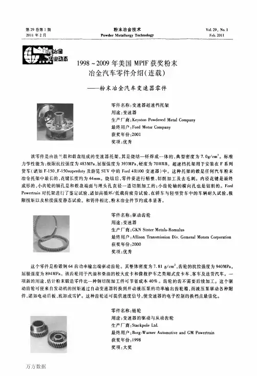
美国mpif标准35“粉末冶金自润滑轴承材料标准”美国mpif标准35“粉末冶金自润滑轴承材料标准”美国mpif标准35“粉末冶金自润滑轴承材料标准”编者按:轴承是机电工业的一类重要通用基础件,据中国机电日报2000年1月19日第6版报道,2000年我国滚动轴承的总生产能力为23亿套,其中中小尺寸普通级滚动轴承可达21亿套。
但很少有人注意到,据初步估计,我国微小型粉末冶金自润滑轴承,即含油轴承,1999年销售量已超过20亿只,且大部分销往国外。
全世界微小型含油轴承年产量已近百亿只。
为适应我国粉末冶金含油轴承生产发展需要,特向有关生产厂家与用户推荐美国mpif标准35《粉末冶金自润滑轴承材料标准》1998年版。
这是国内外thk润滑油的《粉末冶金自润滑轴承材料标准》,值得研究与借鉴。
轴承可定义为一种在其中有另外一种元件(诸如轴颈或杆)旋转或滑动的机械零件。
依据轴承工作时摩擦的型式,它们又分为滚动轴承与滑动轴承。
滑动之中自身具有自润滑性的轴承叫做含油轴承或自润滑轴承。
用粉末冶金法制造的金属基含油轴承通称为粉末冶金自润滑轴承或烧结金属含油轴承。
粉末冶金自润滑轴承是音像设备、微特福州人才网连江马达、办公机械、电动工具、洗衣机、电风扇、缝纫机、复印机等中不可缺少的一类轴承。
据笔者估计,1999年我国微特小型粉末冶金自润滑轴承的年产量已达到25亿只左右。
虽然我国早在1953年就已开始生产thk 润滑油冶金自润滑轴承,也制订过相应的国家标准[1],诸如gb2685-81《粉末冶金筒形轴承型式、尺寸与公差》、gb2686-81《粉末冶金带挡边筒形轴承型式、尺寸与公差》、gb2687-81《粉末冶金球形轴承型式、尺寸与公差》及gb2688-81《滑动轴承粉末冶金轴承技术条件》,但是,这些标准自发布之日起,就从未进行过修订,已不能适应当前科技发展与生产的需要。
国际标准化组织(iso)1996年对iso5755《烧结金属材料规范》进行了修订[2]。
MPIF标准《金属注射成形零件材料标准》————————————————————————————————作者:————————————————————————————————日期:美国MPIF标准35—《金属注射成形零件材料标准》一、MIM零件材料标准的注释和定义(1)MIM材料命名在制定MIM材料的技术规范时,MIM协会采用的牌号系统和AISI-SAE相同。
之所以选用这些牌号名称是因为MIM零件多用于替代已在使用的相应锻轧材料的制品。
当表示某种材料是用MIM工艺制造时,应在材料之前加“MIM”。
例如,用MIM工艺制造的316L不锈钢,可用“MIM-316L”来表示。
在选择某一具体材料之前,需要仔细分析零件的设计与其最终用途,其中包括尺寸公差、零件设计及模具设计。
另外,MIM零件的制造厂家和买方必须商定对成品零件的最终性能要求。
也可规定诸如静态与动态负载、耐磨性、切削性及耐蚀性之类的问题。
(2)一些基本概念与定义最小值概念金属粉末工业联合会对于用于结构零件的粉末冶金材料采用了最小力学性能值概念。
采用MIM工艺制造零件时,可用这些值作为用户选择具体应用材料的一个依据。
为有助于用户选择材料,除最小力学性能值外,还列出了其它性能得标准值。
从而,使用户可选择与确定合适的MIM材料与对具体用途最合适的性能。
提供的数据规定了材料的最小力学性能值,并列出了在工业生产条件下可达到的标准力学性能值。
通过较复杂的工艺过程可增强力学性能和改进其它使用性能。
要选择一种在性能与价格两方面都可行的最佳材料,用户与MIM 零件制造厂家一起讨论零件的用途最为重要。
最小值MIM材料的最小值,对于烧结态和(或)热处理态的所有材料都是用屈服强度(0.2%残余变形法)、极限抗拉强度及伸长率来表示的。
因为MIM材料的密度接近真密度,故其性能和锻轧材料相似。
为建立本标准,所用拉伸性能都是由拉伸试样测定的,拉伸试样是为评定材MIM料专门制备的(关于MIM材料试样的详情见MPIF标准50)。
美国MPIF标准35—《金属注射成形零件材料标准》一、MIM零件材料标准的注释和定义(1)MIM材料命名在制定MIM材料的技术规范时,MIM协会采用的牌号系统和AISI-SAE相同。
之所以选用这些牌号名称是因为MIM零件多用于替代已在使用的相应锻轧材料的制品。
当表示某种材料是用MIM工艺制造时,应在材料之前加“MIM”。
例如,用MIM工艺制造的316L不锈钢,可用“MIM-316L”来表示。
在选择某一具体材料之前,需要仔细分析零件的设计与其最终用途,其中包括尺寸公差、零件设计及模具设计。
另外,MIM零件的制造厂家和买方必须商定对成品零件的最终性能要求。
也可规定诸如静态与动态负载、耐磨性、切削性及耐蚀性之类的问题。
(2)一些基本概念与定义最小值概念金属粉末工业联合会对于用于结构零件的粉末冶金材料采用了最小力学性能值概念。
采用MIM工艺制造零件时,可用这些值作为用户选择具体应用材料的一个依据。
为有助于用户选择材料,除最小力学性能值外,还列出了其它性能得标准值。
从而,使用户可选择与确定合适的MIM材料与对具体用途最合适的性能。
提供的数据规定了材料的最小力学性能值,并列出了在工业生产条件下可达到的标准力学性能值。
通过较复杂的工艺过程可增强力学性能和改进其它使用性能。
要选择一种在性能与价格两方面都可行的最佳材料,用户与MIM 零件制造厂家一起讨论零件的用途最为重要。
最小值MIM材料的最小值,对于烧结态和(或)热处理态的所有材料都是用屈服强度(0.2%残余变形法)、极限抗拉强度及伸长率来表示的。
因为MIM材料的密度接近真密度,故其性能和锻轧材料相似。
为建立本标准,所用拉伸性能都是由拉伸试样测定的,拉伸试样是为评定材MIM料专门制备的(关于MIM材料试样的详情见MPIF标准50)。
由批量生产的零件切削加工的试样或由非标准的MIM试样测定的拉伸性能,可能和按照MPIF 标准50制备的试样测定的结果不同。
在编制MIM材料的技术规范时,表明最小强度值的实际方法是由制造厂家和用户利用生产的第一批零件和相互商定的对零件施加力的方法,进行静态或动态验收试验。
公司制造的铁基粉末冶金零件执行标准与成分性能<一> GB/<二> MPIF-35F-0008-50HT-65HT-75HT-85HT 380450< S 48022HRC60HRC 450520< 5502860 520590< 6203260 590660< 6903560烧结铁和烧结碳钢的化学成分(%).材料牌号Fe CF-0000注: 用差减法求出的其它元素(包括为了特殊目的而添加的其它元素)总量的最大值为%。
▲注: 用差减法求出的其它元素(包括为了特殊目的而添加的其它元素)总量的最大值为%。
烧结铁-铜合金和烧结铜钢的化学成分(%).材料牌号Fe Cu CFC-0200烧结铁-镍合金和烧结镍钢的化学成分(%).材料牌号Fe Ni Cu CFN-0200注: 用差减法求出的其它元素(包括为了特殊目的而添加的其它元素)总量的最大值为%⊙铁-铜合金和铜钢粉末冶金材料性能(MPIF-35)材料编号最小强度(A)(E)拉伸性能横向断裂压缩屈服硬度密度屈服极限极限强度屈服强度伸长率宏观微观铁-镍合金和镍钢粉末冶金材料性能(MPIF-35)↑上一页⊙不锈钢系列粉末冶金制品执行标准与典型牌号的成分和性能-不锈钢(MPIF-35)⊙铜基系列粉末冶金制品执行标准成分与性能-铜基(GB2688-81)<三>"DIN V 30 910" 及"ISO5755" (成分与性能略)⊙烧结铝镍钴永磁合金的磁特性及其它物理特性< 規格二- 不銹鋼>FTG60-25(50R) 材料的力学性能。
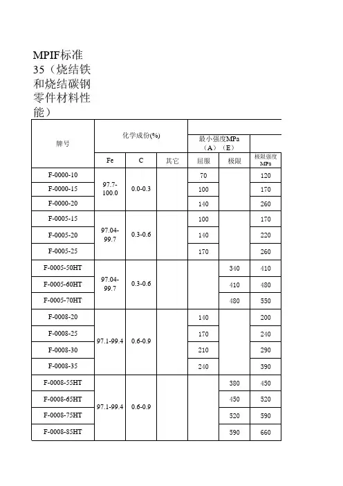
公司制造的铁基粉末冶金零件执行标准与成分性能<一>G B/T14667.1-93物理机械性能材料牌号最小强度(A)(E) 拉伸性能压缩屈服 强度 (0.1%) 硬度密度屈服极限极限 强度屈服强度 (0.2%) 伸长率 (25.4mm) 宏观(表现)微观(表现)MPaMPa MPa % MPa洛氏g/cm 3 F-0000-10-15 -20 70 120 90 1.5 110 40HRF N/A 6.1 100 170 120 2.5 120 60 6.7 140 260 170 7.0 130 80 7.3 F-0005-10-20 -25 100 170 120 <1 125 25HRB N/A 6.1 140 220 160 1.0 160 40 6.6 170260 190 1.5 190 556.9 F-0005-50HT-60HT -70HT 340 410 (D) <0.5 300 20HRC58HRC6.6 410 480 <0.5 360 22 58 6.8 480550 <0.5 420 25 58 7.0 F-0008-20-25 -30 -35 140 200 170 <0.5 190 35HRB N/A5.8 170240 210 <0.5 210 506.2 210 290 240 <1.0 210 60 6.6 240390 2601.0 250 707.0 F-0008-50HT-65HT-75HT -85HT380 450 <0.5S 480 22HRC60HRC6.3 450 520 <0.5 550 28 60 6.6 520 590 <0.5 620 32 60 6.9 590660<0.5690 35 607.1烧结铁和烧结碳钢的化学成分(%). 材料牌号 Fe C F-0000 97.7-100 0.0-0.3 F-0005 97.4-99.7 0.3-0.6 F-0008 97.1-99.4 0.6-0.9 注:用差减法求出的其它元素(包括为了特殊目的 而添加的其它元素)总量的最大值为2.0%。