机械类汽车转向系统外文文献及翻译
- 格式:doc
- 大小:36.50 KB
- 文档页数:5
(1)(2)(3)....112319090234Steering systemMichael Johnson/h_53054590000.htmlSteering systemMotor turning system: On the automobile uses for to change or restores its travel direction to suppose the organization to be called the motor turning system specially. Automobile's steering system is uses for to change the automobile travel direction and to maintain the automobile straight line travel organizationComposes(1)To change the control mechanism basically mainly by the steering wheel, the steering axle, the steering tube column and so on to be composed.the(2) Diverter becomes steering wheel's rotation steering arm's swinging or the rack axis straight reciprocating motion, and to changes the control force to carry on the enlargement the organization. The diverter fixes generally on the automobile frame or the automobile body, changes the control force after the diverter generally will also change the transmission direction.(3)Changes the transmission system the strength which and the movement outputs the diverter passes to the wheel (knuckle), about and causes the wheel to carry on the deflection according to certain relations the organization.TypeCrooked to energy difference, the steering system may divide into themachinery steering system and the power steering system two broad headings crooked.Mechanical steering system: And changes the transmission system by the diverter to be composed.Diverter: By the steering wheel, the steering wheel steering axle, changes meshing to pay (diverter) to be composed.Changes the transmission system: By drop arm (drop arm), drag link, drag link arm, about trapezoidal arm, steering knuckle tie rod, if a dry bulb joint composes.Power steering system: Changes the augmenter constitution by mechanical steering system Canada.1.Mechanical steering systemThe mechanical steering system changes the energy by pilot's physical strength achievement, all power transmission are the machinery. The mechanical steering system by changes the control mechanism, the diverter and changes the transmission system three major part to be composed.(1) Changes control mechanismChanges the control mechanism by the steering wheel, the steering axle, the steering tube column and so on to be composed, its function is rotates the pilot steering wheel's control force to pass to the diverter.(2)D iverterThe diverter (also often is called steering unit) is completes from therotary motion to the translation (or approximate straightline motion) a group of gear mechanism, simultaneously is also in the steering system speed reducer drive. At present the commonly used toothed wheel rack type,follows round the world the crank to refer to sells the type, the worm bearing adjuster crank to refer to sells the type, to follow round the world - the tooth rack tooth fan type, the worm bearing adjuster hoop type and so on. We mainly introduce the first several kinds.1) Gear rack type diverterThe gear rack type diverter divides the both sides output type and among (or single end) the output type two kindsThe both sides output's gear rack type diverter, changes the gear shaft as the transmission vice-host moving parts and installs through the bearing in the diverter shell, its upper extreme through spline and universal joint sliding yoke and steering axle connection. With the steering gear meshing steering rack level arrangement, the both sides with change the steering knuckle tie rod through a ball place to be connected. The spring presses through the briquetting the rack depending in the gear, guarantees ceaseless meshing.S pring's pretightening up force available adjustment thread plug adjustment. When rotates the steering wheel, the diverter gear-driven, causes with it meshing rack along the end motion, thus about causes the steering knuckle tie rod to lead about the knuckle to rotate, causes to change the wheel deflection, thus realizes motor turning.Middle output gear rack type diverter, its structure and principle of work and both sides output gear rack type diverter basic same, the difference lies in it to change the steering knuckle tie rod in steering rack's middle with the bolt with about to be connected. On single-ended output's gear rack type diverter, a rack's end with changes the steering knuckle tie rod through the inside and outside bracket to be connected.2) Follows round the world-like the diverterFollows round the world-like the diverter is one of present domestic and foreign application most widespread structure patterns, generally has two-stage drive, the first level is screw rod nut transmission, the second level is tooth rack tooth fan transmission.In order to reduce between the steering screw steering nut's friction, the two's thread immediate contact, during is loaded with many steel balls, realizes the rolling friction. On the steering screw and the nut processes the profiled outline is two section or three section of not concentric circular arc composition approximate semicircle spiral groove.The two's spiral groove can coordinate to form the approximate circular cross section the spiral tubular channel.The nut side has two pair of through holes, may henceforth the vent plug enter the steel ball in the helix channel. Outside the steering nut has two steel ball drive pipes, each drive pipe's both sides insert the nut side separately in a pair of through hole. In the drive pipe has also packed the steel ball. Thus,in two drive pipes and nut's spiral tubular channels combine two respectively independent seals the steel ball " the flow channel ".When the steering screw rotates, passes to the steering nut through the steel ball the strength, the nut namely along the end motion. At the same time, friction couple function between the screw rod and the nut and under the steel ball, all steel balls then rolls in the spiral tubular channel, formation " ball class ". When the diverter works, two rows steel balls are only in the respective seal flow channel internal recycling, will leave.3)The worm bearing adjuster crank refers to sells the type diverterThe worm bearing adjuster crank refers to sells the type diverter's transmission vice-(by the steering worm primarily moving parts, it is installs from the moving parts in the rocker arm shaft crank nose refers to sells. When the steering worm rotates, refers to with it meshing sells namely circles the rocker arm shaft spool thread along the circular, and leads the rocker arm shaft rotation.(3)Changes the transmission systemChanges the transmission system the function is the strength which and the movement outputs the diverter passes to the steering axle both sides the knuckle, causes the both sides wheering wheel deflection, and causes two wheering wheel deflection angles according to certain relational change, guarantees when motor turning the wheel and the ground relative sliding is as far as possible small.1) Uses for parts with the non-independent suspension fork changes the transmission systemUses for parts with the non-independent suspension fork changes the transmission system mainly to include the steering arm, to change the drag link, the steering, and the steering trapezium. In the front axle is only in the steering axle situation, by changes the steering trapezium general arrangement which the steering knuckle tie rod and the left and right trapezoidal arm are composed after the front axle, when the wheering wheel is in with the automobile straight line travel corresponding neutral point, trapezoidal arm and steering knuckle tie rod in and path parallel plane (horizontal plane) in angle of intersection >90.In the engine position is low or in the steering axle concurrently sufficient driving axle's situation, to avoid the movement interference, often steering trapezium arrangement before the front axle, this time above angle of intersection <90, if the steering arm is not around swings in the automobile fore-and-aft plane, but is shaking right toward left with the path parallel plane, then may change the drag link horizontal, and sells taking advantage of ball leads directly changes the steering knuckle tie rod, thus pushes somebody into doing something the both sides trapezoidal arm rotation.2)Uses for parts with the independent suspension fork changes the transmission systemW hen wheering wheel independent suspension, each wheeringwheel needs to be opposite in the frame makes the independence movement, thus the steering axle must be the separation type. With this corresponding, changes in the transmission system the steering trapezium also to be the separation type.3)Changes the drag linkChanges drag link's function is the strength which and the movement transmits the steering arm passes to the steering trapezium arm (or steering). It receives the strength already has the pulling force, also to have the pressure, therefore the drag link is uses the high quality special steel products manufacture, guarantees the operation reliable. In wheering wheel deflection or because of suspension fork elastic deformation when is opposite beats in the frame, changes the drag link and the steering arm and the steering relative motion is the space motion, for does not have the movement interference, the above three connection uses the pin ball.4)Changes the shock absorberAlong with the vehicle speed enhancement, the modern automobile's wheering wheel will sometimes have the oscillation (wheering wheel to circle king pin spool thread reciprocation swinging, will cause complete bikes automobile body's vibration), not only this will affect automobile's stability, will also affect automobile's comfortableness, the aggravating front wheel tire's attrition. In changes in the transmission system to establish changes the shock absorber is overcomes the wheering wheel oscillation the effective action. Changes the shock absorber an end and the automobile body (or front axle) the hinge, another end and changes the drag link (or diverter) the hinge。
附录BHistoryThe earliest known patent related to power steering was that by Frederick W. Lanchester in the UK,in February 1902. His invention was to "cause the steering mechanism to be actuated by hydraulic power". The next design was filed as recorded by the US Patent Office on August 30, 1932, by Klara Gailis, from Belmont, Massachusetts. There is another inventor credited with the invention of power steering by the name of Charles F. Hammond an American, born in Detroit, who filed similar patents, the first of which was filed as recorded by the Canadian Intellectual Property Office.Chrysler Corporation introduced the first commercially available power steering system on the 1951 Chrysler Imperial under the name Hydraguide. Most new vehicles now have power steering, owing to the trends toward front wheel drive, greater vehicle mass, and wider tires, which all increase the required steering effort. Heavier vehicles as common in some countries would be extremely difficult to maneuver at low speeds, while vehicles of lighter weight may not need power assisted steering at allHydraulic systemsA power steering fluid reservoir and pulley driven pumpMost power steering systems work by using a hydraulic system to turn the vehicle's wheels. The hydraulic pressure is usually provided by a gerotor or rotary vane pump driven by the vehicle's engine. A double-acting hydraulic cylinder applies a force to the steering gear, which in turn applies a torque to the steering axis of the roadwheels. The flow to the cylinder is controlled by valves operated by the steering wheel; the more torque the driver applies to the steering wheel and the shaft it is attached to, the more fluid the valves allow through to the cylinder, and so the more force is applied to steer the wheels in the appropriate direction.One design for measuring the torque applied to the steering wheel is to fix a torsion bar to the end of the steering shaft. As the steering wheel rotates, so does the attached steering shaft, and so does the top end of the attached torsion bar. Since the torsion bar is relatively thin and flexible and the bottom end is not completely free to rotate, the bar will soak up some of the torque; the bottom end will not rotate as far as the top end. The difference in rotation between the top and bottom ends of the torsion bar can be used to control the valve that allows fluid to flow to the cylinder which providessteering assistance; the greater the "twist" of the torsion bar, the more steering assistance will be provided.Since the pumps employed are of the positive displacement type, the flow rate they deliver is directly proportional to the speed of the engine. This means that at high engine speeds the steering would naturally operate faster than at low engine speeds. Because this would be undesirable, a restricting orifice and flow control valve are used to direct some of the pump's output back to the hydraulic reservoir at high engine speeds. A pressure relief valve is also used to prevent a dangerous build-up of pressure when the hydraulic cylinder's piston reaches the end of the cylinder.Some modern implementations also include an electronic pressure relief valve which can reduce the hydraulic pressure in the power steering lines as the vehicle's speed increases (this is known as variable assist power steering).DIRAVIIn the DIRAVI system invented by Citroën, the force turning the wheels comes from the car's high pressure hydraulic system and is always the same no matter what the road speed is. As the steering wheel is turned, the wheels are turned simultaneously to acorresponding angle by a hydraulic piston. In order to give some artificial steering feel, there is a separate hydraulically operated system that tries to turn the steering wheel back to centre position. The amount of pressure applied is proportional to road speed, so that at low speeds the steering is very light, and at high speeds it is very difficult to move more than a small amount from the centre position.As long as there is pressure in the car's hydraulic system, there is no mechanical connection between the steering wheel and the roadwheels. This system was first introduced in the Citroën SM in 1970, and was known as 'VariPower' in the UK and 'SpeedFeel' in the U.S.While DIRAVI is not the mechanical template for all modern power steering arrangements, it did innovate the now common benefit of speed adjustable steering. The force of the centering device increases as the car's road speed increases.Electro-hydraulic systemsElectro-hydraulic power steering systems, sometimes abbreviated EHPS, and also sometimes called "hybrid" systems, use the same hydraulic assist technology as standard systems, but thehydraulic pressure is provided by a pump driven by an electric motor instead of being belt-driven by the engine.In 1965, Ford experimented with a fleet of "wrist-twist instant steering" equipped Mercury Park Lanes that replaced the conventional large steering wheel with two 5-inch (127 mm) rings, a fast 15:1 gear ratio, and an electric hydraulic pump in case the engine stalled.In 1994 Volkswagen produced the Mark 3 Golf Ecomatic, which utilized an electric pump so that the power steering could operate while the engine had been turned off by the computer to save fuel.Electro-hydraulic systems can be found in some cars by Ford, Volkswagen, Audi, Peugeot, Citroen, SEAT, Skoda, Suzuki, Opel, MINI, Toyota, Honda, and Mazda.ServotronicServotronic offers true speed-dependent power steering, in which the amount of servo assist depends on road speed, and thus provides even more comfort for the driver. The amount of power assist is greatest at low speeds, for example when parking the car. The greater assist makes it easier to maneuver the car. At higher speeds, an electronic sensing system gradually reduces the level ofpower assist. In this way, the driver can control the car even more precisely than with conventional power steering. Servotronic is used by a number of automakers, including Audi, BMW, Volkswagen, Volvo, and Porsche. Servotronic is a trademark of AM General Corp.附录C历史已知最早的专利有关的动力转向系统是由弗雷德里克兰彻斯特在英国,在1902年2月。
关于转向系统的外文翻译——中英文翻译、外文The Mazda Speed Sensing Computerised 4-Wheel Steering System. Three and a half decades ago, two young Mazda designers arrived at a far-sighted and well-calculated conclusion that was quite revolutionary for the time. In their technical presentation at the October 26, 1962 Japanese Automotive Engineers' Society Technical Conference, Dr Tadashi Okada and engineer Toshiaki summarised their arduous research concerning vehicle dynamics as follows. The basic difference in the characteristics of oversteer and understeer lies in the magnitude of time delay and response. a vehicle that is stable under high speed must possess understeer characteristics the rear wheel tyre reflects heavily on the stability and a major improvement on control and stability may be anticipated by means of the automatic rear wheel steering system. The conclusions and formulations presented by these two engineers established the foundation for Mazda's present-day reputed suspension technology. Over years of dedicated research and development expertise, their original discoveries and theories have contributed to some of the most significant achievements within the recent history of automotive chassis engineering, incorporated by Mazda within its series production products. These developments include the twin trapezoidal link rearsuspension, first employed in the original front-wheel drive Mazda 323 (1980) and the Mazda 626 (1982), and then perfected within the updated Mazda 626; the award winning Dynamic Tracking Suspension System of the second generation Mazda RX-7 (1985); and the elaborate E-link rear suspension of the new Mazda 929 (1987). While various external forces and loads are exerted to the rear wheels of a vehicle as it combats the elements of the law of motion as defined by Sir Isaac Newton, these new suspension systems convert those forces into "4WS effects" which positively aid in vehicle stability and agility. The Mazda designers' and engineers' ultimate goal was still a positive measure to generate forces for positive controls; a Four-Wheel Steering system. In 1983, Mazda astonished the automotive world with the introduction of an engineering concept car, the MX-02, exhibited at the Tokyo Motor Show. This four-door Sedan, with generous passenger accommodation on an unusually long wheelbase, incorporated among its numerous advanced features a true 4WS system that aided high-speed stability as well as its low-speed manoeuvring. The degree of rear wheel steering was determined by the measurement of both front wheel steering angle and vehicle speed, by means of a central computer unit. The MX-02 was followed by another exciting concept car; the MX-03, first exhibited at the Frankfurt Motor Show in September 1985. This sleek four seat futuristic coupe of the 1990s combined a refined electronically-controlled 4WS system with a continually varyingtorque-split, four-wheel drive system and a powerful three-rotary engine. Mazda Electronically -Controlled Four-Wheel Steering System: A Beneficial Technology Mazda's electronically-controlled, vehicle-speed-sensing Four-Wheel Steering System (4WS) steers the rear wheels in a direction and to a degree most suited to a corresponding vehicle speed range. The system is mechanically and hydraulically actuated, producing greatly enhanced stability, and within certain parameters, agility. The driver of a Mazda 4WS-equipped car derives five strategic benefits, over and above the conventional vehicle chassis. Superior cornering stability Improved steering responsiveness and precision High-speed straightline stability Notable improvement in rapid lane-changing manoeuvres Smaller turning radius and tight-space manoeuvrability at low vehicle speed range The most outstanding advantage of the Mazda 4WS is that it contributes to a notable reduction in driver fatigue over high-speed and extended travelling. This is achieved by optimally: reducing the response delay to steering input and action and eliminating the vehicle's excessive reaction to steering input In essence, by providing the optimum solution to the phenomena researched by the two young Mazda engineers in the early sixties - by the method advocated by them - the 4WS system has emerged as a fully beneficial technology. Strategic Construction The Mazda 4WS consists of a rack-and-pinion front steering system that is hydraulically assisted by a twin-tandem pump mainpower source, with an overall steering ratio of 14.2:1. The rear wheel steering mechanism is also hydraulically assisted by the main pump and electronically controlled - according to the front steering angle and vehicle speed. The rear steering shaft extends from the rack bar of the front steering gear assembly to the rear steering-phase control unit. The rear steering system is comprised of the input end of the rear steering shaft, vehicle speed sensors, a steering-phase control unit (determining direction and degree), a power cylinder and an output rod. A centering lock spring is incorporated, which locks the rear system in a neutral (straightforwa。
Automobile Transmissions and Power Steering Automobiles, trucks, buses, and tractors all depend on transmissions to deliver power from the engine to the wheels, The gasoline and diesel engines that power these vehicles cannot be connected directly to the wheels, because the engines must keep turning at a certain seed to keepfrom stalling. Also, different amount of torque (turning force) must be delivered to the wheels atdifferent times. A large amount of force is needed to get a car moving from a standstill. Less force is needed to keep the car moving once it is rolling. Going up a hill of driving at high speed requires still other amount of force. It is the job of the transmission to deliver the particularamount of force that is needed. The transmission also allows a motor vehicle to back up-----gasoline and diesel engines can run in only one direction, but the transmission can reverse thedirection of the force. And when a car stops, the transmission lets the engine keep running without moving the wheels.The heart of any transmission——even an automatic one—is a set of gears. Gears do notchange the power of an engine, but they can increase the torque by decreasing the speed. They canalso increase the speed by decreasing the torque.The automobile transmission uses a series of gears which enables the engine to continue tovehicle’’s speed is altered. Setting an automobile in operate at maximum efficiency when the vehiclevehicle’’s weight. This motion requires a large amount of power to overcome the inertia of the vehicleprocess requires high engine speed, needed for high power, and a gradual increase in a vehicle’sspeed to avoid a jerky start. To do this, a low gear ratio is allows the crankshaft to revolve several times in order to turn the real axle once. The low gear ratio is used for starting, climbing steep slops, and other situations in which maximum power is required .As power needs are reduced, a second, higher gear ratio is used which rotates the rear axle with fewer revolutions of the crankshaft. As the car’s speed increases, successively higher gear ratios are used until the drive from the engine to the rear wheels passes through the transmission without reduction. Two principle types of transmission are used, manual and automatic.The manual transmission system permits the driver to select the desired gear ratio bymanipulating a shift lever. Besides the forward speed gears, additional gearing is incorporated topermit the vehicle to operate in reverse. Manually operated passenger car transmission used in the United States and Canada usually have there speeds forward and one in reverse. Trucks, tractors, buses, and other heavy-duty vehicles have as many as 10 forward speeds and 2 in reverse. These units are basically five-speed transmissions with a two-speed auxiliary gearbox. Transmission that are to be shifted with the vehicle in motion incorporate synchromesh units to prevent gears from clashing as they are meshed. The synchromesh unit synchronizes the speed of the gears so that they revolve at the same speed as they slide into engagement.The automatic transmission system changes gear ratios automatically in response to changesin engine speed or throttle setting. The use of automatic transmissions increased tremendouslyafter World War Ⅱ, and they are installed in more than half of the automobile produced in the United States. Automobiles equipped with an automatic transmission have a control lever which allows the driver to select neutral, low, drive, and reverse. The engine is started in neutral, and the lever is moved to “drivedrive”” position the drive”” for normal operation when moving forward. In “drivevehicles can accelerate from rest to maximum speed by simply depressing the accelerator. Thelow”” position prevent the transmission from shifting out of the lower gear ratios.“lowIt is used for climbing steep grades, in mud, or at other tomes when maximum power ispark”” position, which locks the transmission to prevent a parked car needed. Some units have a “parkfrom rolling. The automatic transmission makes it easier to drive a car, but it is less efficient than a manually shifted unit and increase gasoline consumption. For this reason, the automatic transmission is not as common in Europe, where economy of operation is a prime sales factor.Four basic types of automatic transmissions have been developed to the point where they have been installed in production vehicles. The first consists of a standard mechanical transmission and clutch which is automatically shifted by pneumatic, hydraulic or electric power units. The second type uses a hydraulic torque converter plus a planetary gear system to increase engine torque. The third system combines a hydraulic coupling with an automatically shifted mechanical gearbox to provide torque amplification. The fourth type uses one or more stages of hydraulic torque conversion to provide torque multiplication.Automatic transmission shift in response to signals from speed sensing and throttle position sensors. The units incorporating hydraulic torque converters use the hydraulic fluid, under pressure, to engage and disengage planetary gear trains.Power steering system 也是汽车重要的一部分,The car of today is larger and heavier than earlier cars; the tyres are wider, further apart and inflated to lower pressures .In addition, the trend of development has been to place more than half the weight on the front wheels, especially the weight of the engine , which itself is larger and heavier than in the early days.To make cars easier to steer, the gear ratio in the steering box at the end of the steering column was changed to that turning the wheel required less torque, but this increased the number of turns of the steering wheel required on modern cars without power steering compared to 2.5 or 3 turns for cars built before 1940. Modern cars with power steering only require about three turns.Power assisted steering was first developed in the 1920s; one of the first devices was developed by an engineer at Pierce Arrow, an American make of luxury cars. The Cadillac division of General Motors was going to offer power steering as optional equipment on some models in the early 1930s, but the depression interfered with development. During World War Ⅱ power steering was fitted to military vehicles; in 1952 Chrysler began offering it , and it is now standard equipment on many of the biggest American cars .Electric devices were tried , but power steering today is always hydraulic , with oil pressure of perhaps 1000 psi (70kg/cm2) maintained by a pump driven by the engineer of the car . The system is a servomechanism, or servo loop, which makes a correction to compensate for the torque applied to the steering wheel by the driver. It consists of an actuator and a control valve. The actuator is a hydraulic cylinder with a piston, or ram, which is free to travel in either direction from the center. The function of the control valve is to respond to the torque from the steering wheel by actuating smaller valves at each end of the cylinder. The system is designed to assist the steering linkage, rather than to replace it, and it does not do all of the work of steering , but leaves some of it for the driver. Thus if the hydraulics fail the car can still be steered , though with greater effort, and at all times the feel of the road is mechanically transmitted from the front wheels to the hands of the hands of the driver on the steering wheel, an essential element of safe driving. The power steering makes a positive contribution to safe driving in that if the driver hits a small obstacle in the road or has a flat tyre at speed, the power unit makes it easier to keep the car under control. Many large cars fitted with wide, stiff radial ply tyres would be nearly impossible to steerat parking speeds without power steering.Hydrostatic systems, designed for off-the-road vehicles, are exception to some of this, because they dispense with the steering column and the steering box , and the steering wheel and the steered wheels are connected only by hydraulic tubes or hoses.The power steering system includes a reservoir to hold the oil. Oil pressure is always provided when the engine is running, but when the system is at rest, that is when the steering wheel is not being turned, equal pressure is available to each side of the piston in the actuator, so that it does not move.There are basically two types of power steering system: those which have the control valve located within the steering box, in which case it is usually a rotary valve, and those in which the valve is integral with actuator, when it is an axial spool valve.汽车传动系与动力转向装置轿车、卡车、公交车以及拖拉机都靠汽车传动系将动力从发动机输送到车轮上。
中英文对照外文翻译文献(文档含英文原文和中文翻译)原文:The Track Vehicle Changes Direction Research Present Condition and DevelopmentTrends of The Organization1 change direction the research present condition of the organizationDifferent classification in basis method, the track vehicle changes direction organization can according to vehicle is in change direction process the power flows of deliver the way is divided into the single power flows to changedirection the organization to flow to change direction the organization with a power, and also can according to in change direction process two the sport of side trackses have no the contact but is divided into the independent type change direction the organization with bad soon the type changes direction the organization.1.1 single powers establish a certain changing direction the organization after flowing change direction the single power in organization flow to change direction the general structure in organization method is at became soon the organization, is the most simple method to constitute track vehicle change direction to spread to move.The single power flows to change direction the organization to change direction the organization most in brief, among them most in common usely change direction the clutch, single bad soon the machine, double is bad soon the machine, planet changes direction organization etc..Change direction the clutch[1,2] is all a friction that several types rub the clutch, depending the friction surface to deliver to turn the , being the separation some on changing direction the clutch laterally, can reduce or cut off that side drive a round delivers of turn the make vehicle changed direction.Change direction the size of the radius from drive a decrease for spreads to turn the measures namely the degree that clutch separate decides.Change direction the clutch is simple because of the construction, manufacturing convenience, got the extensive application on the small scaled track in inside in earlier period type tractor, bulldozer.But because its manipulate the sex bad, produce the efficiency low, can consume bigger, enlarge continuously along with the track vehicle power, change direction the application of the clutch will suffer certainly of restrict.SingleBad soon the machine changes direction the organization[2,3] can make vehicle several why the speed of the center position still keeps in change direction process the original driving the car straightly is soon, being a When the complete system in side move, change direction the radius over small, but another side track speed over high, change direction the Cape speed over big, for this reason a power for needing changing direction power very bigly, would outrunninggenerally launching machine restrict, if the pilot keep on changing direction, have a little bit the immodesty and then will make launch the machine fire, as a result can depend to slip to whet, using than the greater half path changes direction, or pole is not fair and softly break to change direction continuously with the lesser half path.Therefore this kind of is single bad soon the machine change direction the organization to no longer adopt almost now.The speed that a speed for differing soon machine changing direction organization[3,4] can making track vehicle at changing direction slowly soon side track lowering is equal to the fast side track the increment, the for this reason vehicle changes direction of average speed and straightly the speed that drive same alike.But because a variety for badly soon machine can't completely system moving first side track, vehicle can't originally changing direction, and changing direction radius scope has no usage to change direction the clutch big, changing direction the going smoothly worse.While changing direction, the fast side track accelerates, therefore launching the affixture of the machine carry the ratio adoption change direction the clutch big.The double is bad soon the machine be constituted by wheel gear of change direction the organization, with change direction the clutch compare the spare parts number little, bear to whet the sex good, the life span is longer.The planet changes direction the organization[4,5] moves with the system from a planet a department the machine constitutes.The operation planet the system on the organization moves the machine can change two sides drives the round drives the dint size make vehicle changed direction.It is that type of to change direction the organization opposite in change direction the clutch change direction the organization can deliver the bigger changing direction the dint , can realize an athletic and fixed stalk wheel gear organization fall through of two free a planet for of flat-out decomposition with synthesizing, planet organization a three dollar as have the bad relating to soon; change direction the organization to much order to deliver the motive, and the internal path in organization faces the dint mutually equilibrium.But is complicated because of its construction, only industry in big power tractor, bulldozer and other heavy type vehicle last application.Single weakness thatpower change direction is obvious, vehicle only contain several fix of change direction the radius, press to rule not of change direction When the radius change direction, want to is slipped by friction a piece to whet to realize, and is hard to get the stability change direction the radius accurately; the next in order in change direction process rub a dollar piece of violent slip to whet to will bring to have fever with wear away, make spread to move the efficiency lower, especially in the big power change direction work appearance next, would exsit the bigger power lose, with the result that often need to be declined to change direction soon; moreover, the violent friction also make easy damage in organization, cause the work dependable bad, the life span lower.1.2 pairs of powerses flow to change direction the organization after launching machine, will launch the machine power be divided in to become soon with change direction two roads be juxtaposed to deliver, ising a double of powers to flow to change direction the organization.A power flows to change direction the organization will used for keeping the pushes forward of become soon the organization is different from result in leftly, the right side track speed differs of change direction the organization to be juxtaposed in spread move department, change direction the organization when the vehicle keeps the did not result in twoth the speed of side trackses are bad, while changing direction, became to flow each file of offering soon to drive the speed straightly with change direction the organization results in of two the speed of side trackses differ to remit to flow, realizing the vehicle change direction.(1)the machine type a power flow to change direction the organization to flow the foundation top that change direction the organization to appear at the earliest stage in the single power of was a machine to kept the with changed direction two powers flowed all from machinery to realized type a power to flowed to change direction the organization[3].It is this kind to change direction the organization main from two become soon box( a lord become soon the box, a cent moves a box of), the planet wheel gear organization, clutch moves with the planet organization system the machine constitutes, the single power flows to change direction in changing direction function the organization has the very bigincreasing, but it still change direction the radius is to have the class.The file is more low, getting of change direction the radius more small; the file is more high, getting of change direction the radius more big.Can't still adapt to the vehicle road in all different curvatures on the tactful track that change direction to drive with the demand, also can't expel parts of coalescences rub a piece proceeds to slip to whet to change direction and from slip to whet an a series of problem for bringing.(2)the machine liquid press type a power flows to change direction the organization machineThe type of changes direction the organization changes direction the function easily under the influence of the pilot's driver's technique, physical strength term moving the machine to wear away with the clutch, system, and bring the pilot the fatigue easily.Give or get an electric shock along with the machine the liquid press and technical development in engineering in machine in person, the machine type change direction the organization to will be eliminated on the big power tractor, bulldozer...etc. engineering vehicle necessarily.Press in the last additional liquid in system in machine the liquid of —that pump the motor presses the machine — liquid drives to press to change direction the system will get the application gradually.The machine liquid press type a power flows to change direction the organization[5,6] from launch the machine and change the deal pump, control valve, fixed amount motor, many files become soon box and empress bridges change direction to differ to move the organization constitutes.It will spread to flow from the machine that launch the machine power in many files became soon the importation stalk of the box last cent flow, all the way flow through was pressed by liquid pump- liquid press motor constitute of change direction adjust soon system; another all the way flow through many files became soon box, finally experienced star row top confluence, then was lined up by planet of some a the parts( such as planet) spread to the vehicle to spread to move the stalk top eventually.Because the liquid presses to pump to press with the liquid the motor can have no the class controls, therefore using the this type of changing direction the organization since can acquire the carAn a lot of weakness for twoth lateral speeds differing realizing having no class controling, again overcoming machine type changing direction organization.If the liquid presses the motor do not work, only coming from central spread the dynamic power flow, the vehicle makes the straight line drives; if only have the liquid that come from the power press the motor flows, the vehicle can realize to change direction radius as the zero changing direction originally; if input at the same time two road powers flow, because the liquid presses the motor can realize to have no the class controls, for this reason vehicle two side tracks drive the rotation to have soon and will barely do much more endless, can get the much more endless changes direction the radius, can immediately realize to have no the class changes direction, pilot as long as manipulate to change direction the dish turns to move the liquid presses the device, can make vehicle driven along the certain arc stablely.This kind of changes direction the organization not only have the construction good, have no the friction a piece, life span is long, the efficiency is high and work dependable, arrange simple, maintain the adjustment little and lower to can consume to wait the characteristics the outside, but also it is not a motive to pass the part or cut off all a side track in working function to the system move a the side drives a the round realizes to change direction of, but two side tracks deliver the motive always, can realizes nicely like this the motive change direction, basic ascend a safety for slippery phenomenon, being applicable to proceeding being partial to carrying pushing soil with cutting off root homework; at sloping fields changing direction can't appearing" conversing direction" phenomenon, increases vehicle that dissolves the track; because of changing direction do not cut off the motive, the average car of the for this reason vehicle does not lower soon; the track do not stop driving, breaking to the soil little, in loosenning soft soil of pass the sex good; change direction the size of the radius can control arbitrarily, increasing the flexibility of the track vehicle, change direction steady; change direction vehicle can develop with drive the high work in same function straightly; realizes easily a the root manipulates the pole to control in to back with change direction.2 change direction the pure liquid in trend(1)in development in organization press to have no the class changes direction the organization wants to realize the track vehicle changes direction the radius can control and continue to have no the class changes of change direction the function, the adoption capacity type liquid presses to pump to press with the liquid motor etc. has no the class become soon a piece is a more realistic viable method.The pure liquid presses to change direction the organization[7 9] of ~ss pass to pump of positive and negative two directions have no the class changes the deal regulates, realizing to launch the mobile dint was spread by double to move to change direction the road arrives to remit the popular star row has no the class changes of spreading and moving ratio, end realize the vehicle face or so two change direction laterally radius can continue to have no the class the variety keeps the , pass the liquid press to pump with the liquid press the motor shuts the lock( change the row that deal pump measureses for zero) to realize to change direction the zero to shut the lock axially, from but keeps to keep the stablely.Under the situation of becoming soon the organization hangs the blank on schedule to change direction, launch machine a power for sending out all to press from the liquid that change direction the road a piece deliver, can realize the vehicle change direction originally.The current liquid presses the industry level returns the hard getting the power enough and big and the good liquid in function presses a dollar an efficiency for, and the liquid presses the system low, this is the biggest obstacle that pure liquid press to have no the class change direction the technique develops.(2)the compound changes direction organization as to overcome the pure liquid presses the above blemish that change direction the organization, appearing now the small liquid in power in various adoptions press the liquid of a dollar piece presses the compound changes direction the project[7].A pump a motor project: this project is to solves the liquid press the direct and the most simple project in shortage in a power in a dollar, its function press with pure liquid to change direction same, but two sets of liquids press a piece merge to make the organization's physical volume weight bigger, the efficiency is still lower.The machine liquid presses to reunite the project: that project is adopting adouble of flowing the liquid press to change direction of at the same time, reserve a set of machines change direction the organization.Make use of the power not very of the liquid presses a dollar the piece realizes the greater half path changes direction of have no the class variety continuously; make use of the organization that machine change direction lesser half path realizes the class changes direction.This kind of change direction the organization falls through whole radius scope has no the class variety.A radius liquid presses to change direction the project: that project adoption contain two kinds of exportations soon the liquid that compare presses the motor, when the good road ascends to change direction adoption the higher exportation turns soon, native out of fix the hour then change to output with the low speed to overcome bigger changing direction the resistance.The liquid presses the liquid dint compound changes direction the project: that project presses with the liquid of the limited power a piece proceeds to have no the class changes direction, the help matches the machine accidentally at change direction the liquid press the motor dint not enough hour on time provide the help .That project although reduce the liquid press a piece efficiencies would be much lower.In fine, adopt the liquid press a dollar a point for having no class becoming soon characteristic to realizing track vehicle having no class changing direction is good choice, solving liquid pressing a dollar a power shortage then is low with the efficiency that direction is investigative.(3)the machine liquid presses the consecution has no the class changes direction the organization machine liquid presses the consecution has no the class changes direction the organization[10 21] of ~ss are in simple liquid pressing cent in machine spreading the foundation that move the principle, adopting the different machine organization parameter combine, and press with liquid a dollar the piece matches with of a kind of latest model changes direction the organization.It can guarantee at continue to have no the class output the next applied small liquid in premise that turn to press the total power in an exportation for significantly increasing vehicle in a dollar soon, and its spread to move the efficiency far far ahead pure the liquid presses to change direction theorganization spreads to move the efficiency.It represents the development direction that track vehicle change direction organization.The research develops the good machine in function liquid presses the consecution has no the class changes direction the organization, excellent turn to match the that type of turning. Construction parameter that face organization is the point lesson of the current vehicle engineering realm.履带车辆转向机构的研究现状及发展趋势1、转向机构的研究现状依据不同的分类方法,履带车辆转向机构可根据车辆在转向过程中功率流的传递方式分为单功率流转向机构和双功率流转向机构,也可根据在转向过程中两侧履带的运动有无联系而分为独立式转向机构和差速式转向机构。
浙江科技学院机械与汽车工程学院技术实习外文翻译题目电动助力转向系统专业车辆工程班级102 班姓名吴总荣学号110015036 指导教师程峰完成日期2013年 12月22日Electronic power-assisted steering systemWhat it isElectrically powered steering uses an electric motor to drive either the power steering hydraulic pump or the steering linkage directly. The power steering function is therefore independent of engine speed, resulting in significant energy savings.How it works :Conventional power steering systems use an engine accessory belt to drive the pump, providing pressurized fluid that operates a piston in the power steering gear or actuator to assist the driver.In electro-hydraulic steering, one electrically powered steering concept uses a high efficiency pump driven by an electric motor. Pump speed is regulated by an electric controller to vary pump pressure and flow, providing steering efforts tailored for different driving situations. The pump can be run at low speed or shut off to provide energy savings during straight ahead driving (which is most of the time in most world markets).Direct electric steering uses an electric motor attached to the steering rack via a gear mechanism (no pump or fluid). A variety of motor types and gear drives is possible.A microprocessor controls steering dynamics and driver effort. Inputs include vehicle speed and steering, wheel torque, angular position and turning rate.Working In Detail:A "steering sensor" is located on the input shaft where it enters the gearbox housing. The steering sensor is actually two sensors in one: a "torque sensor" that converts steering torque input and its direction into voltage signals, and a "rotation sensor" that converts the rotation speed and direction into voltage signals. An "interface" circuit that shares the same housing converts the signals from the torque sensor and rotation sensor into signals the control electronics can process.Inputs from the steering sensor are digested by a microprocessor control unit thatalso monitors input from the vehicle's speed sensor. The sensor inputs are then compared to determine how much power assist is required according to a preprogrammed "force map" in the control unit's memory. The control unit then sends out the appropriate command to the "power unit" which then supplies the electric motor with current. The motor pushes the rack to the right or left depending on which way the voltage flows (reversing the current reverses the direction the motor spins). Increasing the current to the motor increases the amount of power assist.The system has three operating modes: a "normal" control mode in which left or right power assist is provided in response to input from the steering torque and rotation sensor's inputs; a "return" control mode which is used to assist steering return after completing a turn; and a "damper" control mode that changes with vehicle speed to improve road feel and dampen kickback.If the steering wheel is turned and held in the full-lock position and steering assist reaches a maximum, the control unit reduces current to the electric motor to prevent an overload situation that might damage the motor. The control unit is also designed to protect the motor against voltage surges from a faulty alternator or charging problem.The electronic steering control unit is capable of self-diagnosing faults by monitoring the system's inputs and outputs, and the driving current of the electric motor. If a problem occurs, the control unit turns the system off by actuating a fail-safe relay in the power unit. This eliminates all power assist, causing the system to revert back to manual steering. A dash EPS warning light is also illuminated to alert the driver. To diagnose the problem, a technician jumps the terminals on the service check connector and reads out the trouble codes.Electric power steering systems promise weight reduction, fuel savings and package flexibility, at no cost penalty.Europe's high fuel prices and smaller vehicles make a fertile testbed for electric steering, a technology that promises automakers weight savings and fuel economy gains. And in a short time, electric steering will make it to the U.S., too. "It's just just a matter of time," says Aly Badawy, director of research and development for Delphi Saginaw Steering Systems in Saginaw, Mich. "The issue was cost and that's behind us now. By 2002 here in the U.S. the cost of electric power steering will absolutely be a wash over hydraulic."Today, electric and hybrid-powered vehicles (EV), including Toyota's Prius and GM's EV-1, are the perfect domain for electric steering. But by 2010, a TRW Inc. internal study estimates that one out of every three cars produced in the world will be equipped with some form of electrically-assisted steering. The Cleveland-based supplier claims its new steering systems could improve fuel economy by up to 2 mpg, while enhancing handling. There are true bottom-line benefits as well for automakers by reducing overall costs and decreasing assembly time, since there's no need for pumps, hoses and fluids.Another claimed advantage is shortened development time. For instance, a Delphi group developed E-TUNE, a ride-and-handling software package that can be run off a laptop computer. "They can take that computer and plug it in, attach it to the controller and change all the handling parameters -- effort level, returnability, damping -- on the fly," Badawy says. "It used to take months." Delphi has one OEM customer that should start low-volume production in '99.Electric steering units are normally placed in one of three positions: column-drive, pinion-drive and rack-drive. Which system will become the norm is still unclear. Short term, OEMs will choose the steering system that is easiest to integrate into an existing platform. Obviously, greater potential comes from designing the system into an all-new platform."We have all three designs under consideration," says Dr. Herman Strecker, group vice president of steering systemsdivision at ZF in Schwaebisch Gmuend, Germany. "It's up to the market and OEMs which version finally will be used and manufactured.""The large manufacturers have all grabbed hold of what they consider a core technology," explains James Handysides, TRW vice president, electrically assisted steering in Sterling Heights, Mich. His company offers a portfolio of electric steering systems (hybrid electric, rack-, pinion-, and column-drive). TRW originally concentrated on what it still believes is the purest engineering solution for electric steering--the rack-drive system. The system is sometimes refered to as direct drive or ball/nut drive.Still, this winter TRW hedged its bet, forming a joint venture with LucasVarity. The British supplier received $50 million in exchange for its electric column-drive steering technology and as sets. Initial production of the column and pinion drive electric steering systems is expected to begin in Birmingham, England, in 2000."What we lack is the credibility in the steering market," says Brendan Conner, managing director, TRW/LucasVarity Electric Steering Ltd. "The combination with TRW provides us with a good opportunity for us to bridge that gap." LucasVarity currently has experimental systems on 11 different vehicle types, mostly European. TRW is currently supplying its EAS systems for Ford and Chrysler EVs in North America and for GM's new Opel Astra.In 1995, according to Delphi, traditional hydraulic power steering systems were on 7596 of all vehicles sold globally. That 37-million vehicle pool consumes about 10 million gallons in hydraulic fluid that could be superfluous, if electric steering really takes off.The present invention relates to an electrically powered drive mechamsm for providing powered assistance to a vehicle steering mechanism. According to one aspect of the present invention, there is provided an electrically powered driven mechanism for providing powered assistance to a vehicle steering mechanism having a manually rotatable member for operating the steering mechanism, the drive mechanism including a torque sensor operable to sense torque being manually applied to the rotatable member, an electrically powered drive motor drivingly connected to the rotatable member and a controller which is arranged to control the speed and direction of rotation of the drive motor in response to signals received from the torque sensor, the torque sensor including a sensor shaft adapted for connection to the rotatable member to form an extension thereof so that torque is transmitted through said sensor shaft when the rotatable member is manually rotated and a strain gauge mounted on the sensor shaft for producing a signal indicative of the amount of torque being transmitted through said shaft.Preferably the sensor shaft is non-rotatably mounted at one axial end in a first coupling member and is non-rotatably mounted at its opposite axial end in a second coupling member, the first and second coupling members being inter-engaged to permit limited rotation therebetween so that torque under a predetermined limit is transmitted by the sensor shaft only and so that torque above said predetermined limit is transmitted through the first and second coupling members.The first and second coupling members are preferably arranged to act as a bridge for drivingly connecting first and second portions of the rotating member to one another.Preferably the sensor shaft is of generally rectangular cross-section throughout the majority of its length.Preferably the strain gauge includes one or more SAW resonators secured to the sensor shaft.Preferably the motor is drivingly connected to the rotatable member via a clutch.Preferably the motor includes a gear box and is concentrically arranged relative to the rotatable member.Various aspects of the present invention will hereafter bedescribed, with reference to the accompanying drawings, in which :Figure 1 is a diagrammatic view of a vehicle steering mechanism including an electrically powered drive mechanism according to the present invention,Figure 2 is a flow diagram illustrating interaction between various components of the drive mechanism shown in Figure 1 ,Figure 3 is an axial section through the drive mechanism shown in Figure 1, Figure 4 is a sectional view taken along lines IV-IV in Figure 3,Figure 5 is a more detailed exploded view of the input drives coupling shown in Figure 3, andFigure 6 is a more detailed exploded view of the clutch showing in Figure 3. Referring initially to Figure 1 , there is shown a vehicle steering mechanism 10 drivingly connected to a pair of steerable road wheels The steering mechanism 10 shown includes a rack and pinion assembly 14 connected to the road wheels 12 via joints 15. The pinion(not shown) of assembly 14 is rotatably driven by a manually rotatable member in the form of a steering column 18 which is manually rotated by a steering wheel 19.The steering column 18 includes an electric powered drive mechanism 30 which includes an electric drive motor (not shown in Figure 1) for driving the pinion in response to torque loadings in the steering column 18 in order to provide power assistance for the operative when rotating the steering wheel 19.As schematically illustrated in Figure 2, the electric powered drive mechanism includes a torque sensor20 which measures the torque applied by the steering column 18 when driving the pinion and supplies a signal to a controller 40. The controller 40 is connected to a drive motor 50 and controls the electric current supplied to the motor 50 to control the amount of torque generated by the motor 50 and the direction of its rotation.The motor 50 is drivingly connected to the steering column 18 preferably via a gear box 60, preferably an epicyclic gear box, and a clutch 70. The clutch 70 is preferably permanently engaged during normal operation and is operative under certain conditions to isolate drive from the motor 50 to enable the pinion to be driven manually through the drive mechanism 30. This is a safety feature to enable the mechanism to function in the event of the motor 50 attempting to drive the steering column too fast and/or in the wrong direction or in the case where the motor and/or gear box have seized.The torque sensor 20 is preferably an assembly including a short sensor shaft on which is mounted a strain gauge capable of accurately measuring strain in the sensor shaft brought about by the application of torque within a predetermined range.Preferably the predetermined range of torque which is measured is 0-lONm; more preferably is about l-5Nm.Preferably the range of measured torque corresponds to about 0-1000 microstrain and the construction of the sensor shaft is chosen such that a torque of 5Nm will result in a twist of less than 2°in the shaft, more preferably less than 1 ° .Preferably the strain gauge is a SAW resonator, a suitable SAW resonator being described in WO91/13832. Preferably a configuration similar to that shown in Figure 3 of WO91/13832 is utilised wherein twoSAW resonators are arranged at 45° to the shaft axis and at 90°to one another.Preferably the resonators operate with a resonance frequency of between 200-400 MHz and are arranged to produce a signal to the controller 40 of 1 MHz ±500 KHz depending upon the direction of rotation of the sensor shaft. Thus, when the sensor shaft is not being twisted due to the absence of torque, it produces a 1 MHz signal.When the sensor shaft is twisted in one direction it produces a signal between 1.0 to 1.5 MHz. When the sensor shaft is twisted in the opposite direction it produces a signal between 1.0 to 0.5 MHz. Thus the same sensor is able to produce a signal indicative of the degree of torque and also the direction of rotation of the sensor shaft.Preferably the amount of torque generated by the motor inresponse to a measured torque of between 0-10Nm is 0-40Nm and for a measured torque of between l-5Nm is 0-25Nm.Preferably a feed back circuit is provided whereby the electric current being used by the motor is measured and compared by the controller 40 to ensure that the motor is running in the correct direction and providing the desired amount of power assistance. Preferably the controller acts to reduce the measured torque to zero and so controls the motor to increase its torque output to reduce the measured torque.A vehicle speed sensor (not shown) is preferably provided which sends a signal indicative of vehicle speed to the controller. The controller uses this signal to modify the degree of power assistance provided in response to the measured torque.Thus at low vehicle speeds maximum power assistance will be provided and a high vehicle speeds minimum power assistance will be provided.The controller is preferably a logic sequencer having a field programmable gate array for example a XC 4005 as supplied by Xilinx. Such a controller does not rely upon software and so is able to function more reliably in a car vehicle environment. It is envisaged that a logic sequence not having a field programmable array may be used.Electronic power steering system (English as EPS), and hydraulic power steering system (HPS) compared to, EPS has many advantages.The advantage is that the EPS:1) high efficiency. HPS efficiency is very low, generally 60% to 70%, while EPS and electrical connections, high efficiency, and some can be as high as 90 percent.2) less energy consumption. Automobile traffic in the actual process, at the time to about 5 percent of the time travelling, the HPS system, engine running, the pumps will always be in working condition, the oil pipeline has been in circulation, so that vehicle fuel consumption rate by 4 % To 6%, while EPS only when needed for energy, vehicle fuel consumption rates only increased by 0.5 percent.3) "Road sense of" good. Because EPS internal use of rigid, system of the lag can be controlled by software, and can be used in accordance with the operation of the driver to adjust.4) back to being good. EPS simple structure of small internal resistance, is a good back, get back to being the best characteristics, improve vehicle handling and stability.5) little environmental pollution. HPS hydraulic circuit in the hydraulic hoses and connectors, the existence of oil leaking, but hydraulic hoses can not be recovered, the environmental pollution are to a certain extent, while EPS almost no pollution to the environment.6) can be independent of the engines work. EPS for battery powered devices, as long as sufficient battery power, no matter what the condition for the engine, can produce power role.7) should have a wide range.8) easy to assemble and good layout.Now, power steering systems of some cars have become the standard-setting, the whole world about half of the cars used to power steering. With the development of automotive electronics technology, some cars have been using electric power steering gear, the car of the economy, power and mobility has improved. Electric power steering device on the car is a new power steering system device, developed rapidly in recent years both at home and abroad, because of its use of programmable electronic control devices, the flexibility in the same time there are also potential safety problems. In the analysis This unique product on the basis of the author of the characteristics of electronic control devices, security clearance just that the factors that deal with securitymeasures, and discussed a number of concerns the safety of specific issues. The results show that : Existing standards can not meet the electric power steering device security needs and made the electric power steering device safety evaluation of the idea. Research work on the electric power steering device development and evaluation of reference value.电动助力转向系统图1电动助力转向系统的工作原理:电动助力转向系统是通过一个电动机来驱动动力方向盘液压泵或直接驱动转向联动装置。

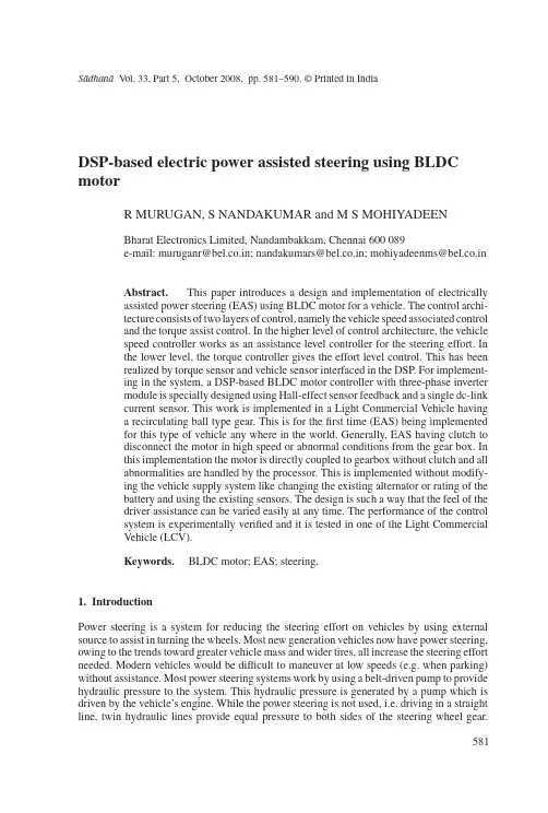
S¯a dhan¯a V ol.33,Part5,October2008,pp.581–590.©Printed in IndiaDSP-based electric power assisted steering using BLDC motorR MURUGAN,S NANDAKUMAR and M S MOHIYADEENBharat Electronics Limited,Nandambakkam,Chennai600089e-mail:muruganr@bel.co.in;nandakumars@bel.co.in;mohiyadeenms@bel.co.inAbstract.This paper introduces a design and implementation of electricallyassisted power steering(EAS)using BLDC motor for a vehicle.The control archi-tecture consists of two layers of control,namely the vehicle speed associated controland the torque assist control.In the higher level of control architecture,the vehiclespeed controller works as an assistance level controller for the steering effort.Inthe lower level,the torque controller gives the effort level control.This has beenrealized by torque sensor and vehicle sensor interfaced in the DSP.For implement-ing in the system,a DSP-based BLDC motor controller with three-phase invertermodule is specially designed using Hall-effect sensor feedback and a single dc-linkcurrent sensor.This work is implemented in a Light Commercial Vehicle havinga recirculating ball type gear.This is for thefirst time(EAS)being implementedfor this type of vehicle any where in the world.Generally,EAS having clutch todisconnect the motor in high speed or abnormal conditions from the gear box.Inthis implementation the motor is directly coupled to gearbox without clutch and allabnormalities are handled by the processor.This is implemented without modify-ing the vehicle supply system like changing the existing alternator or rating of thebattery and using the existing sensors.The design is such a way that the feel of thedriver assistance can be varied easily at any time.The performance of the controlsystem is experimentally verified and it is tested in one of the Light CommercialVehicle(LCV).Keywords.BLDC motor;EAS;steering.1.IntroductionPower steering is a system for reducing the steering effort on vehicles by using external source to assist in turning the wheels.Most new generation vehicles now have power steering, owing to the trends toward greater vehicle mass and wider tires,all increase the steering effort needed.Modern vehicles would be difficult to maneuver at low speeds(e.g.when parking) without assistance.Most power steering systems work by using a belt-driven pump to provide hydraulic pressure to the system.This hydraulic pressure is generated by a pump which is driven by the vehicle’s engine.While the power steering is not used,i.e.driving in a straight line,twin hydraulic lines provide equal pressure to both sides of the steering wheel gear.581582R Murugan,S Nandakumar and M S MohiyadeenWhen torque is applied to the steering wheel,the hydraulic lines provide unequal pressures and hence assist in turning the wheels in the intended direction.Electric Power Steering systems use electric components with no hydraulic systems at all.Sensors detect the motion and torque of the steering column and a computer module applies assistive power via an electric motor coupled directly to either the steering gear or steering column.This allows varying amounts of assistance to be applied depending on driving conditions.In the event of component failure,a mechanical linkage such as a rack and pinion serves as a back-up in a manner similar to that of hydraulic systems.Electric systems have an advantage in fuel efficiency because there is no hydraulic pump constantly running. Their other big advantage is the elimination of a belt-driven engine accessory,and several high-pressure hydraulic hoses between the hydraulic pump,mounted on the engine,and the steering gear,mounted on the chassis.This greatly simplifies manufacturing.The demand of electrically assisted power steering(EAS)has rapidly increased in past few years because of energy savings compared to Hydraulic Power Steering(HPS).Alternating current(ac)motors are designed to be highly efficient and easily controlled with modern power circuitry.Because of the developments in switching techniques,it is quite feasible to use ac motors with a battery supply as source.The traditional worm gear driven dc motor system is constrained by the limitations of the dc motor brushes and size of the motor for the same torque of BLDC.In this case BLDC motor has been used as an actuator in the application for electric power steering.The BLDC motor provides high torque and easy control(Chan &Fang2002;Chu et al2001;Desai&Emadi2005;Jun-Uk Chu et al2004;Kevin Brown et al1990;NamhunKim et al2007).The basic mechanical properties of the vehicle are essentially invariant among all of the available brands.The electrically assisted power steering system consists of BLDC motor mounted to the frame of the steering column and coupled to the wheels through a worm speed reducer.Electrically assisted power steering is shown in figure1.An electrically assisted power steering is composed of several parts such as torque sensor, engine speed sensor,vehicle speed sensor,steering column,torsion bar and electronic control unit.Figure1.Electrically assisted power steering.DSP-based electric power assisted steering using BLDC motor583 Torque sensor output gives the torque difference to be developed by the motor to reduce the effort required by the driver while he is steering.Engine speed signal is required to start the assistance only when the engine is ON in order to save the battery life.Vehicle speed signal is required to control the assistance developed by the motor(for the same level of torque signal)at various vehicle speed,as assistance requirement comes down as speed of the vehicle increases.The control architecture consists of two layers of control,namely the assistance level control and the torque control.In the higher level of control architecture,vehicle speed signal works as a reference for controlling the assistance to be developed by the motor.In the inner layer torque sensor signal performs generation of torque.The torque output from motor is a function of torque sensor signal and it depends on the torque difference between the steering wheel and the wheel.The vehicle speed signal and engine speed signals are pulses with variable frequency.For system implementation,a DSP-based BLDC motor controller with three-phase inverter module is specially designed using Hall-effect sensor feedback and a single dc-link current sensor.The torque and Back EMF equations of BLDC motor are similar to that of dc motor.The current sensing is ensured by a low cost shunt resistor and used for over-current protection and current feedback.The current control is achieved by PID controller and pulse width modulation(PWM) signals with varying duty rates.Hall-effect sensors are available to detect rotor shaft position, used for electronic commutation,motor speed and direction of rotation.2.Hardware architectureA block diagram of the power assisted steering is illustrated infigure2.The electrically assisted power steering system in a vehicle consists of the following parts.a.Digital signal processorb.Driver and protection cardc.Three phase inverterd.BLDC motor with Hall sensore.Reduction gear and sensors.Figure2.Block diagram of EAS.584R Murugan,S Nandakumar and M S MohiyadeenFigure3.DSP and protection card.2.1ProcessorThe DSP used for control and computation is TMS320F24XX.The processor is a single chip solution based on40MIPS,16bitfixed point DSP core with several associated peripherals such as Pulse Width Modulation generator(PWM)and Analog to Digital Converter(ADC) BPRA0551997;SPRU160C1999;SPRU161C1999.2.2Driver and protection circuitThe selected MOSFET Driver is from IR family.The PWM signals coming from the DSP are combined with protection logics and connected to MOSFET driver.The output of the driver is directly connected to the MOSFET switches through series gate resistor.The current sensing is done by the low cost shunt resistor.The voltage drop is processed with analog amplifier and connected to ADC module and used for current feedback and over-current protection.The protection card used here is shown in thefigure3.2.3Three phase inverter moduleThe three phase inverter module is developed by using MOSFETs with low ON state drop and high switching frequency.The three-phase inverter card used is shown infigure4.Figure4.MOSFET card.DSP-based electric power assisted steering using BLDC motor585Figure5.BLDC motor equivalent circuit.2.4BLDC motor with Hall sensorThe equivalent circuit of a BLDC motor is shown infigure5.The BLDC motor used here has8magnetic pole pairs on the rotor and a three-phase star connected windings on stator. The voltage equation of BLDC motor can be represented as⎡⎣V aV bV c⎤⎦=⎡⎣R000R000R⎤⎦⎡⎣i ai bi c⎤⎦+⎡⎣L000L000L⎤⎦ddt⎡⎣i ai bi c⎤⎦+⎡⎣e ae be c⎤⎦(1)R=Phase resistanceL=Phase inductanceV a,V b,V c=Phase voltagesI a,i b,i c=Phase currentse a,e b,e c=Back EMFs.The generated motor torque is given byT=e a i a+e b i b+e c i cω,(2)whereωis motor angular velocity.The motor is equipped with three Hall effect sensors.The Hall sensors produce three180◦(electrical)overlapping signals as shown in thefigure6.Thus it is providing six mandatory commutation points.The Hall sensor outputs are directly connected to processor and it generate the necessary switching sequence as per commutation.2.5Gear box and sensing circuitsThe BLDC motor is connected to a reduction gear system as shown infigure7.It drives the wheel.The torque difference between the steering wheel and wheel is sensed by a torsion bar.The output of the torsion bar is sensed by the torque sensor.The output of the torque sensor is directly connected to ADC for processing.586R Murugan,S Nandakumar and M S MohiyadeenFigure6.Hall sensor wave form.3.Controller design3.1Effort level controlThe electrically assisted power steering(EAS)incorporates a brushless electric motor located on the steering column,on the pinion that assists the driver when rmation like engine speed,and torque required are transmitted in real time to a DSP which deter-mines the optimal degree of assistance the electric motor should apply.Figure8shows the effort required by the driver without assistance and with assistance for a vehicle at static.Electrically assisted power steering eliminates the need for hydraulicfluids and complicated mechanical components(such as servo pumps),hydraulic lines,belts and pulleys,which add weight and volume.By eliminating the hydraulic pump,the EAS can operate without the help of the engine.Unlike a conventional hydraulic system,the EAS consumes energy only when providing assistance.The control algorithm for the electrically assisted steering system is shown infigure9.The effective torque and velocity control of a BLDC motor is based on relatively simple torque and Back EMF equations,which are similar to those of the DC motor.Figure7.Gear box with motor.DSP-based electric power assisted steering using BLDC motor587Figure8.Effort curve. During any120degree interval of phase current,I the instantaneous power(P)being converted from electrical to mechanical isP=ωT e=2EI(3)T e=Electromagnetic torqueE=Induced EMF per phase.The‘2’in this equation arises from the fact that two-phase are conducting.E=2NphB g Lrω,per phase induced emf.(4)Nph=Number of winding turns per phaseB g=Rotor magneticfield densityL=Length of the rotorr=Internal radius of rotor.Figure9.Control algorithms.588R Murugan,S Nandakumar and M S MohiyadeenUsing the above expression the electromagnetic torque is given by,T e=4NphBgLrI=KφI(5)K=Torque constantφ=Flux per pole pair.The system takes torque reference(I−ref)and feedback line current(Ifb)as input,produces duty-cycle reference as output.This is actually a PI controller.The following equation is implementedD−cycle=K p(I−ref−If b)+K pT i(I−ref−If b)dt,(6)Kp=Proportional constantT i=Time constant.Limiters are there atfinal controller output.Duty cycle reference is clamped to the peak of the saw tooth carrier wave.Current control is achieved by Pulse Width Modulation(fixed frequency20kHz)signals with varying duty cycles.PWM width is determined by comparing the measured actual current with the desired reference current.To sum up,the Back EMF is directly proportional to the motor velocity and the torque production is almost directly proportional to the phase current.In this control scheme,torque production follows the principle that current shouldflow in only two of the three phases at a time.Only one current at a time needs to be controlled so that only one current sensor is necessary.The positioning of the current sensor allows the use of a low cost resistor as a shunt.3.2Assistance level controlFigure10shows the effort required to be produced by the motor for various vehicle speeds.Variable steering assistance(higher at low vehicle speed and lower at high vehiclespeed),Figure10.Boost curve for various speeds.DSP-based electric power assisted steering using BLDC motor589Figure11.Driving effort outputfrom EAS.which improves drivability and active safety.This has been implemented by sensing the vehicle speed and accordingly modifies the effort to be produced by the electric motor by controlling reference to the controller.4.Experimental resultsIn this section,the result is presented(figure11)to ensure the validity of the proposed method at static driving.From the abovefigure,we can see that the effort required by the driver is almost constant entire steering wheel rotation.The effort reduction comes around75%.The motor is selected such that the cogging torque is very less.The maximum peak cogging torque of the motor used at10rpm is0·0056Nm compared to peak torque of2·45Nm.The acceleration and deceleration of the motor is done in such a way that the driver does not feel the torque ripple in his hand.The torque ripple generally felt at low speed,here the system in a loop such that the system is always in acceleration/deceleration phase,so feel of torque ripple is less.Further to above,the mechanical system itself is in variable gear ratio and it has inherent torque variation more than the motor torque ripple produced by the motor.Hence the driver is not able to feel the torque ripple compared with EAS ON mode and EAS OFF mode.From this result,it is seen that the proposed EAS has performed as expected.Maximum torque required(manual):32NmTorque required during power assistance:8NmPercentage assistance provided:75%Average current consumption:8A5.ConclusionFor equivalent power steering efficiency,electrically assisted power steering improves fuel consumption by4percent or more compared to conventional hydraulic systems.The elimina-tion of hydraulicfluids is also more environmentally friendly for End of Life Vehicle(ELV) consideration.Electronic data management(wheel angle,vehicle speed,etc.)can be used to fine-tune the power steering parameters,enhancing the car drivability.Variable steering assis-tance improves drivability and active safety.Steering force feedback incorporates controlled re-centre positioning of the steering wheel and active damping of highway vibration.590R Murugan,S Nandakumar and M S MohiyadeenReferencesBPRA055March1997DSP Solutions for BLDC motors.Literature number:Texas Instruments Europe Chan Lie-Tong Yan F,Shao-Yuan Fang2002In-Wheel permanent-magnet brushless dc motor drive for an electric bicycle.IEEE Trans.Energy Conversion17(2):229–232Chu C L,Tsai M C,Chen H Y2001Torque control of brushless DC motors applied to electric vehicles.IEEE Trans.on1–5Desai,Ali Emadi2005A novel digital control technique for brushless DC motor drives:Current control.IEEE Trans.326–331Jun-Uk Chu,In-Hyuk Moon,Gi-Won Choi,Jei-Cheong Ryu,Mu-Seong Mun2004Design of BLDC motor controller for electric power wheelchair.IEEE Trans.94–95Kevin E Brown,Rafael M Inigo,Barry W Johnson1990Design,implementation,and testing of an adaptable optimal controller for an electric wheelchair.IEEE Trans.on Industry Application26(6): 1144–1157NamhunKim,Hamid A Toliyat,Issa M Panahi,Min-Huei Kim2007BLDC motor control algorithm for low-cost industrial applications.IEEE Trans.1400SPRU160C June1999TMS320F/C24x DSP Controllers reference guide CPU and instruction set.Literature number:Texas Instruments EuropeSPRU161C June1999TMS320F/C240DSP controllers reference guide—Peripheral library and spe-cific devices.Literature number:Texas Instruments Europe。
附录2中文翻译汽车转向系统的发展历史及未来技术趋势屈裕丰(合肥工业大学,机械汽车工程学院)摘要:转向系统是整车系统中必不可少的最基本的组成系统,驾驶者通过方向盘来操纵和控制汽车的行进方向,从而实现自己的驾驶意图。
一百多年来,汽车工业随着机械和电子技术的发展而不断前进。
到今天,汽车已经不是单纯机械意义上的汽车了,它是机械、电子、材料等学科的综合产物。
汽车转向系统也随着汽车工业的发展历经了长时间的演变。
本文介绍了汽车转向系统的历史及未来的技术发展趋势。
关键词:转向系统;转向器;液压助力传统的汽车转向系统是机械式的转向系统,汽车的转向由驾驶员控制方向盘,通过转向器等一系列机械转向部件实现车轮的偏转,从而实现转向。
随着上世纪五十年代起,液压动力转向系统在汽车上的应用,标志着转向系统革命的开始。
汽车转向动力的来源由以前的人力转变为人力加液压助力。
液压助力系统HPS(Hydraulic Power Steering)是在机械式转向系统的基础上增加了一个液压系统而成。
该液压系统一般与发动机相连,当发动机启动的时候,一部分发动机能量提供汽车前进的动能,另外一部分则为液压系统提供动力。
由于其工作可靠、技术成熟至今仍被广泛应用。
这种助力转向系统主要的特点是液压力支持转向运动,减小驾驶者作用在方向盘上的力,改善了汽车转向的轻便性和汽车运行的稳定性行的稳定性。
但同时液压助力系统也存在一些缺点:在车辆设计制造完成后,车辆转向的助力特性不能改变。
直接后果是,当助力特性偏向于低速助力时,汽车在低速段可以得到很好的助力,但是在高速段需要有较好路感的时候,由于助力特性不能调节,使得驾驶者没有较好的路感;当助力特性偏向于高速助力时,在低速段得不到很好的助力效果;即使车辆不转向,液压系统也必须在发动机的带动下工作。
其结果是,消耗发动机能量,增加油耗;存在液压油泄漏问题,不仅对环境造成污染,而且容易使其他部件损坏;在低温下,液压系统的工作性能比较差。
附录A 外文文献Electric Power Steering system1.HistoryIn automobile development course, Steering system experienced four stages of development: from the initial mechanical Steering system (for your DNS setting Steering, abbreviation ) development for Hydraulic Steering system (Hydraulic Power Steering, abbreviation HPS), then again appeared electronically controlled Hydraulic Steering system (Electro Hydraulic Power Steering, abbreviation EHPS) and Electric Power Steering system (Steering, room Power as EPS). Assemble mechanical steering system of car parking and low-speed driving, when the driver's steering control burden too heavy, in order to solve this problem, the American GM in the 1950s took the lead in the car hydraulic steering system. But, hydraulic steering system can't juggle vehicles to speed portability and high speed, so the steering stability Koyo in Japan in 1983, with the company introduced the application of speed sensing function of hydraulic steering system. This new type of steering system can provide speed increased with the decreasing steering, but complicated structure, cost is higher,and cannot overcome hydraulic system itself has many shortcomings, is a cross between a hydraulic steering and electric power steering the transition between the products. In 1988, Japan Suzuki company first in small cars equipped with Cervo Koyo company development on the steering column, power type electric power steering system; In 1990, Japan Honda NSX in sports car company adopted self-developed rack power type electric power steering system, henceforth unveils the electric power steering in cars applications history2.Working principleElectric power steering system are as follows: first, the working principle, torque sensor measured on steering wheel drivers on the manipulation of the moment, the wheel speed sensors detect the vehicle driving speed, then present the two signals to ECU; According to the built-in control strategy: ECU, calculates the ideal target booster torque, into current instructions to motor; Then, the power generated by the torque motor slowdown institutions amplification on steering system in mechanical manipulation of the moment, and the driver together to overcome resistance torque, realize to the vehicle steering.3. Working processElectric power steering system as traditional hydraulic system alternative products has entered into the auto manufacturing. And had predicted instead, EPS not only applicable to small cars, and some for 12V medium vehicle installed electric system.EPS system includes the following components:The torque sensor: detection steering wheel motion and vehicle motion situation;Electronic control units: according to provide the torque sensor the size of the signal computing power;Motor: according to the electronic control units; turn power output value generationReduction gear: improve motor power, and produce turn it sends to steering mechanism.Other vehicle system control algorithm input information is provided by the car CAN bus (for example steering Angle and bus speed, etc.). Motor drive also need other information, such as motor rotor position and the three-phase motor sensor (current sensor provided). Motor control by four MOSFET, due to micro controller cannot direct drive of large gate capacitance, MOSFET using drive IC form needed the interface, for safety, complete motor control system must implement monitoring,motor control system integration in PCB, usually contains a relay, the relay use, as the main switch under the condition of the fault detection, disconnect motor and electronic control units.Micro control device must control EPS system and have brushless motor. Micro control device according to the torque sensor provide needed the steering wheel torque information, forming a current control loop. In order to improve the security of the system level, the micro control device should have an on-board oscillator, so even in external oscillator malfunction case, also ensure micro control device performance, also should have chip watchdog. Infineon XC886 integration of the company all the important micro control device component, other safety features for through the software to realize, if must implement safety standards IEC61508 industries, you have to finish all kinds of diagnosis and self-inspection task and increase micro control device work load. At present different customers use of torque sensor and rotor position sensor difference is very big. They use different measuring principle, such as decomposing machine, magnetic resonance device, based on the integration of giant magnet or stance sensor.The role of power levels is switch electric current. The power level has two main functions: drive IC control andprotection MOSFET, MOSFET itself and to be responsible for switch currents. MOSFET and partition.Micro control device PWM output port provides driver current and voltage is too low, can't directly connected with MOSFET screen realization. Drive IC role is to provide enough current, the grid to charge for MOSFET, so that in the and discharge 20kHz conditions, and ensure the normal realization switch for discretion side provides the high bar source voltage MOSFET, ensure that you get the low conduction resistance. If the high side MOSFET in open state, to source potential close battery level. Want to make MOSFET arrived at nominal conduction resistance, gate to higher than 8V source voltage. MOSFET completely conduction needed the most ideal voltage is required, therefore 10V or above a grid of potential than battery voltage 10V is higher. Charge pump is to ensure that the function to the largest extent reduce MOSFET power (even if low battery voltage conditions) circuit.The other key charge pump design according to different characteristics that can be PWM pattern request, achieve extremely low (low to 1%) and high rate of 390v (high to 100%). Drive IC another important function is testing, avoid damage toshort-circuit mosfets, affected MOSFET will be closed, diagnosis submitted to micro control device.附录B 外文文献的中文翻译电动助力转向系统1.发展历史在汽车的发展历程中,转向系统经历了四个发展阶段:从最初的机械式转向系统(Manual Steering,简称MS)发展为液压助力转向系统(Hydraulic Power Steering,简称HPS),然后又出现了电控液压助力转向系统(Electro Hydraulic Power Steering,简称EHPS)和电动助力转向系统(Electric Power Steering,简称EPS)。
中英文对照资料外文翻译文献Spin control for carsStability control systems are the latest in a string of technologies focusing on improved diriving safety. Such systems detect the initial phases of a skid and restore directional control in 40 milliseconds, seven times faster than the reaction time of the average human. They correct vehicle paths by adjusting engine torque or applying the left- or-right-side brakes, or both, as needed. The technology has already been applied to the Mercedes-Benz S600 coupe.Automatic stability systems can detect the onset of a skid and bring a fishtailing vehicle back on course even before its driver can react.Safety glass, seat belts, crumple zones, air bags, antilock brakes, traction control, and now stability control. The continuing progression of safety systems for cars has yielded yet another device designed to keep occupants from injury. Stability control systems help drivers recover from uncontrolled skids in curves, thus avoiding spinouts and accidents.Using computers and an array of sensors, a stability control system detects the onset of a skid and restores directional control more quickly than a human driver can. Every microsecond, the system takes a "snapshot," calculating whether a car is going exactly in the direction it is being steered. If there is the slightest difference between where the driver is steering and where the vehicle is going, the system corrects its path in a split-second by adjusting engine torque and/or applying the cat's left- or right-side brakes as needed. Typical reaction time is 40 milliseconds - seven times faster than that of the average human.A stability control system senses the driver's desired motion from the steering angle, the accelerator pedal position, and the brake pressure while determining the vehicle's actual motion from the yaw rate (vehicle rotation about its vertical axis) and lateral acceleration, explained Anton van Zanten, project leader of the Robert Bosch engineering team. Van Zanten's group and a team of engineers from Mercedes-Benz, led by project manager Armin Muller, developed the first fully effective stability control system, which regulates engine torque and wheel brake pressures using traction control components to minimize the difference between the desired and actual motion.Automotive safety experts believe that stability control systems will reduce the number of accidents, or at least the severity of damage. Safety statistics say that most of the deadly accidents in which a single car spins out (accounting for four percent of all deadly collisions) could be avoided using the new technology. The additional cost of the new systems are on the order of the increasingly popular antilock brake/traction control units now available for cars.The debut of stability control technology took place in Europe on the Mercedes-Benz S600 coupe this spring. Developed jointly during the past few years by Robert Bosch GmbH and Mercedes-Benz AG, both of Stuttgart, Germany, Vehicle Dynamics Control (VDC). in Bosch terminology, or the Electronic Stability Program (ESP), as Mercedes calls it, maintains vehicle stability in most driving situations. Bosch developed the system, and Mercedes-Benz integrated it into the vehicle. Mercedes engineers used the state-of-the-art Daimler-Benz virtual-reality driving simulator in Berlin to evaluate the system under extreme conditions, such as strong crosswinds. They then put the system through its paces on the slick ice of Lake Hornavan near Arjeplog, Sweden. Work is currently under way to adapt the technology to buses and large trucks, to avoid jack-knifing, for example.Stability control systems will first appear in mid-1995 on some European S-Class models and will reach the U.S. market during the 1996 model year (November 1995 introduction). It will be available as a $750 option on Mercedes models with V8 engines, and the following year it will be a $2400 option on six-cylinder 鉣俕嶏핤딿냷 $1650 of the latter price is for the traction control system, a prerequisite for stability control.Bosch is not alone in developing such a safety system. ITT Automotive of Auburn Hills, Mich., introduced its Automotive Stability Management System (ASMS) in January at the 1995 North American International Auto Show in Detroit. "ASMS is a quantum leap in the evolution of antilock brake systems, combining the best attributes of ABS and traction control into a total vehicle dynamics management system," said Timothy D. Leuliette, ITT Automotive's president and chief executive officer."ASMS monitors what the vehicle controls indicate should be happening, compares that to what is actually happening, then works to compensate for the difference," said Johannes Graber, ASMS program manager at ITT Automotive Europe. ITT's system should begin appearing on vehicles worldwide near the end of the decade, according to Tom Mathues, director of engineering of Brake & Chassis Systems at ITT Automotive North America. Company engineers are now adapting the system to specific car models from six original equipment manufacturers.A less-sophisticated and less-effective Bosch stability control system already appears on the 1995 750iL and 850Ci V-12 models from Munich-based BMW AG. The BMW Dynamic Stability Control (DSC) system uses the same wheel-speed sensors as traction control and standard anti-lock brake (ABS) systems to recognize conditions that can destabilize a vehicle in curves and corners. To detect such potentially dangerous cornering situations, DSC measures differences in rotational speed between the two front wheels. The DSC system also adds a sensor for steering angle, Utilizes an existing one for vehicle velocity, and introduces its own software control elements in the over allantilock-brake/traction-control/stability-control system.The new Bosch and ITT Automotive stability control systems benefit from advanced technology developed for the aerospace industry. Just as in a supersonic fighter, the automotive stability control units use a sensor-based computer system to mediate between the human controller and the environment - in this case, the interface between tire and road. In addition, the system is built around a gyroscopelike sensor design used for missile guidance.BEYOND ABS AND TRACTION CONTROLStability control is the logical extension of ABS and traction control, according to a Society of Automotive Engineers paper written by van Zanten and Bosch colleagues Rainer Erhardt and Georg Pfaff. Whereas ABS intervenes when wheel lock is imminent during braking, and tractioncontrol prevents wheel slippage when accelerating, stability control operates independently of the driver's actions even when the car is free-rolling. Depending on the particular driving situation, the system may activate an individual wheel brake or any combination of the four and adjust engine torque, stabilizing the car and severely reducing the danger of an uncontrolled skid. The new systems control the motion not only during full braking but also during partial braking, coasting, acceleration, and engine drag on the driven wheels, circumstances well beyond what ABS and traction control can handle.The idea behind the three active safety systems is the same: One wheel locking or slipping significantly decreases directional stability or makes steering a vehicle more difficult. If a car must brake on a low-friction surface, locking its wheels should be avoided to maintain stability and steerability.Whereas ABS and traction control prevent undesired longitudinal slip, stability control reduces loss of lateral stability. If the lateral forces of a moving vehicle are no longer adequate at one or more wheels, the vehicle may lose stability, particularly in curves. What the driveɲ逾半쀹ᾩ쏪 ﲢ끣 "fishtailing" is primarily a turning or spinning around the vehicle's axis. A separate sensor must recognize this spinning, because unlike ABS and traction control, a car's lateral movement cannot be calculated from its wheel speeds.SPIN HANDLERSThe new systems measure any tendency toward understeer (when a car responds slowly to steering changes), or over-steer (when the rear wheels try to swing around). If a car understeers and swerves off course when driven in a curve, the stability control system will correct the error by braking the inner (with respect to the curve) rear wheel. This enables the driver, as in the case of ABS, to approach the locking limit of the road-tire interface without losing control of the vehicle. The stability control system may reduce the vehicle's drive momentum by throttling back the engine and/or by braking on individual wheels. Conversely, if the hteral stabilizing force on the rear axle is insufficient, the danger of oversteering may result in rear-end breakaway or spin-out. Here, the system acts as a stabilizer by applying the outer-front wheel brake.The influence of side slip angle on maneuverability, the Bosch researchers explained, shows that the sensitivity of the yaw moment on the vehicle, with respect to changes in the steeringangle, decreases rapidly as the slip angle of the vehicle increases. Once the slip angle grows beyond a certain limit, the driver has a much harder time recovering by steering. On dry surfaces, maneuverability is lost at slip-angle values larger than approximately 10 degrees, and on packed snow at approximately 4 degrees.Most drivers have little experience recovering from skids. They aren't aware of the coefficient of friction between the tires and the road and have no idea of their vehicle's lateral stability margin. When the limit of adhesion is reached, the driver is usually caught by surprise and very often reacts in the wrong way, steering too much. Oversteering, ITT's Graber explained, causes the car to fishtail, throwing the vehicle even further out of control. ASMS sensors, he said, can quickly detect the beginning of a skid and momentarily activate the brakes at individual wheels to help return the vehicle to a stable line.It is important that stability control systems be user-friendly at the limit of adhesion - that is, to act predictably in a way similar to normal driving.The biggest advantage of stability control is its speed - it can respond immediately not only to skids but also to shifting vehicle conditions (such as changes in weight or tire wear) and road quality. Thus, the systems achieve optimum driving stability by changing the lateral stabilizing forces.For a stability control system to recognize the difference between what the driver wants (desired course) and the actual movement of the vehicle (actual course), current cars require an efficient set of sensors and a greater computer capacity for processing information.The Bosch VDC/ESP electronic control unit contains a conventional circuit board with two partly redundant microcontrollers using 48 kilobytes of ROM each. The 48-kB memory capacity is representative of the large amount of "intelligence" required to perform the design task, van Zanten said. ABS alone, he wrote in the SAE paper, would require one-quarter of this capacity, while ABS and traction control together require only one half of this software capacity.In addition to ABS and traction control systems and related sensors, VDC/ESP uses sensors for yaw rate, lateral acceleration, steering angle, and braking pressure as well as information on whether the car is accelerating, freely rolling, or braking. It obtains the necessary information on the current load condition of the engine from the engine controller. The steering-wheel anglesensor is based on a set of LED and photodiodes mounted in the steering wheel. A silicon-micromachine pressure sensor indicates the master cylinder's braking pressure by measuring the brake fluid pressure in the brake circuit of the front wheels (and, therefore, the brake pressure induced by the driver).Determining the actual course of the vehicle is a more complicated task. Wheel speed signals, which are provided for antilock brakes/traction control by inductive wheel speed sensors, are required to derive longitudinal slip. For an exact analysis of possible movement, however, variables describing lateral motion are needed, so the system must be expanded with two additional sensors - yaw rate sensors and lateral acceleration sensors.A lateral accelerometer monitors the forces occurring in curves. This analog sensor operates according to a damped spring-mass mechanism, by which a linear Hall generator transforms the spring displacement into an electrical signal. The sensor must be very sensitive, with an operating range of plus or minus 1.4 g.YAW RATE GYROAt the heart of the latest stability control system type is the yaw rate sensor, which is similar in function to a gyroscope. The sensor measures the speed at which the car rotates about its vertical axis. This measuring principle originated in the aviation industry and was further developed by Bosch for large-scale vehicle production. The existing gyro market offers two widely different categories of devices: $6000 units for aerospace and navigation systems (supplied by firms such as GEC Marconi Avionics Ltd., of Rochester, Kent, U.K.) and $160 units for videocameras. Bosch chose a vibrating cylinder design that provides the highest performance at the lowest cost, according to the SAE paper. A large investment was necessary to develop this sensor so that it could withstand the extreme environmental conditions of automotive use. At the same time, the cost for the yaw rate sensor had to be reduced so that it would be sufficiently affordable for vehicle use.The yaw rate sensor has a complex internal structure centered around a small hollow steel cylinder that serves as the measuring element. The thin wall of the cylinder is excited with piezoelectric elements that vibrate at a frequency of 15 kilohertz. Four pairs of these piezo elements are arranged on the circumference of the cylinder, with paired elements positionedopposite each other. One of these pairs brings the open cylinder into resonance vibration by applying a sinusoidal voltage at its natural frequency to the transducers; another pair, which is displaced by 90 degrees, stabilizes the vibration. At both element pairs in between, so-called vibration nodes shift slightly depending on the rotation of the car about its vertical axis. If there is no yaw input, the vibration forms a standing wave. With a rate input, the positions of the nodes and antinodes move around the cylinder wall in the opposite direction to the direction of rotation (Coriolis acceleration). This slight shift serves as a measure for the yaw rate (angular velocity) of the car.Several drivers who have had hands-on experience with the new systems in slippery cornering conditions speak of their cars being suddenly nudged back onto the right track just before it seems that their back ends might break away.Some observers warn that stability controls might lure some drivers into overconfidence in low-friction driving situations, though they are in the minority. It may, however, be necessary to instruct drivers as to how to use the new capability properly. Recall that drivers had to learn not to "pump" antilock brake systems.Although little detail has been reported regarding next-generation active safety systems for future cars (beyond various types of costly radar proximity scanners and other similar systems), it is clear that accident-avoidance is the theme for automotive safety engineers. "The most survivable accident is the one that never happens," said ITT's Graber. "Stability control technology dovetails nicely with the tremendous strides that have been made to the physical structure and overall capabilities of the automobile." The next such safety system is expected to do the same.汽车的转向控制控制系统稳定性是针对提高驾驶安全性提出的一系列措施中最新的一个。
附录A 外文文献Electric Power Steering system1.HistoryIn automobile development course, Steering system experienced four stages of development: from the initial mechanical Steering system (for your DNS setting Steering, abbreviation ) development for Hydraulic Steering system (Hydraulic Power Steering, abbreviation HPS), then again appeared electronically controlled Hydraulic Steering system (Electro Hydraulic Power Steering, abbreviation EHPS) and Electric Power Steering system (Steering, room Power as EPS). Assemble mechanical steering system of car parking and low-speed driving, when the driver's steering control burden too heavy, in order to solve this problem, the American GM in the 1950s took the lead in the car hydraulic steering system. But, hydraulic steering system can't juggle vehicles to speed portability and high speed, so the steering stability Koyo in Japan in 1983, with the company introduced the application of speed sensing function of hydraulic steering system. This new type of steering system can provide speed increased with the decreasing steering, but complicated structure, cost is higher,and cannot overcome hydraulic system itself has many shortcomings, is a cross between a hydraulic steering and electric power steering the transition between the products. In 1988, Japan Suzuki company first in small cars equipped with Cervo Koyo company development on the steering column, power type electric power steering system; In 1990, Japan Honda NSX in sports car company adopted self-developed rack power type electric power steering system, henceforth unveils the electric power steering in cars applications history2.Working principleElectric power steering system are as follows: first, the working principle, torque sensor measured on steering wheel drivers on the manipulation of the moment, the wheel speed sensors detect the vehicle driving speed, then present the two signals to ECU; According to the built-in control strategy: ECU, calculates the ideal target booster torque, into current instructions to motor; Then, the power generated by the torque motor slowdown institutions amplification on steering system in mechanical manipulation of the moment, and the driver together to overcome resistance torque, realize to the vehicle steering.3. Working processElectric power steering system as traditional hydraulic system alternative products has entered into the auto manufacturing. And had predicted instead, EPS not only applicable to small cars, and some for 12V medium vehicle installed electric system.EPS system includes the following components:The torque sensor: detection steering wheel motion and vehicle motion situation;Electronic control units: according to provide the torque sensor the size of the signal computing power;Motor: according to the electronic control units; turn power output value generationReduction gear: improve motor power, and produce turn it sends to steering mechanism.Other vehicle system control algorithm input information is provided by the car CAN bus (for example steering Angle and bus speed, etc.). Motor drive also need other information, such as motor rotor position and the three-phase motor sensor (current sensor provided). Motor control by four MOSFET, due to micro controller cannot direct drive of large gate capacitance, MOSFET using drive IC form needed the interface, for safety, complete motor control system must implement monitoring,motor control system integration in PCB, usually contains a relay, the relay use, as the main switch under the condition of the fault detection, disconnect motor and electronic control units.Micro control device must control EPS system and have brushless motor. Micro control device according to the torque sensor provide needed the steering wheel torque information, forming a current control loop. In order to improve the security of the system level, the micro control device should have an on-board oscillator, so even in external oscillator malfunction case, also ensure micro control device performance, also should have chip watchdog. Infineon XC886 integration of the company all the important micro control device component, other safety features for through the software to realize, if must implement safety standards IEC61508 industries, you have to finish all kinds of diagnosis and self-inspection task and increase micro control device work load. At present different customers use of torque sensor and rotor position sensor difference is very big. They use different measuring principle, such as decomposing machine, magnetic resonance device, based on the integration of giant magnet or stance sensor.The role of power levels is switch electric current. The power level has two main functions: drive IC control andprotection MOSFET, MOSFET itself and to be responsible for switch currents. MOSFET and partition.Micro control device PWM output port provides driver current and voltage is too low, can't directly connected with MOSFET screen realization. Drive IC role is to provide enough current, the grid to charge for MOSFET, so that in the and discharge 20kHz conditions, and ensure the normal realization switch for discretion side provides the high bar source voltage MOSFET, ensure that you get the low conduction resistance. If the high side MOSFET in open state, to source potential close battery level. Want to make MOSFET arrived at nominal conduction resistance, gate to higher than 8V source voltage. MOSFET completely conduction needed the most ideal voltage is required, therefore 10V or above a grid of potential than battery voltage 10V is higher. Charge pump is to ensure that the function to the largest extent reduce MOSFET power (even if low battery voltage conditions) circuit.The other key charge pump design according to different characteristics that can be PWM pattern request, achieve extremely low (low to 1%) and high rate of 390v (high to 100%). Drive IC another important function is testing, avoid damage toshort-circuit mosfets, affected MOSFET will be closed, diagnosis submitted to micro control device.附录B 外文文献的中文翻译电动助力转向系统1.发展历史在汽车的发展历程中,转向系统经历了四个发展阶段:从最初的机械式转向系统(Manual Steering,简称MS)发展为液压助力转向系统(Hydraulic Power Steering,简称HPS),然后又出现了电控液压助力转向系统(Electro Hydraulic Power Steering,简称EHPS)和电动助力转向系统(Electric Power Steering,简称EPS)。
附录附录ASteering Behavior and Control Technology0f Four—wheel Steering AutomobiIeABSTRACTThis paper analyses the characteristics of car four-wheel steering control to, summarizes the principle of construction four-wheel steering cars. Introduced the four-wheel steering system control strategy. Points out the four-wheel steering system control technology faces difficulties, and prospects the trend of its development.Keywords: four-wheel steering; Steering characteristics; Working principle; Control; Development;1. IntroductionWith modern road traffic system and the development of modern automobile technology, people on the car's steering control performance and driving stability requirement is increasing day by day. As the most effective improve vehicle handling performance of a kind of active chassis control technology - four-wheel steering technology. In the 1980s began in cars get application, and as the modern automobile industry and continuous development. Car four-wheel steering means in turn, the rear car can be relative to body active steering, that the car can be up to four wheels role. To improve the car turned to maneuverability, handling stability and driving safety.2. The car's steering four-wheel steering2.1 4ws cars and 2ws steering process analysisOrdinary two wheel steering can not only the front car around its own wheel rotation and relative to body deflection around the precision, then wheel rotation and not only deflection. When the driver turned the steering wheel, front wheel steering, changed directions face front tyre, produced a transverse force, through the front wheel effect on body, make the body yawing and produce centrifugal force, the rear wheels cornering,produced change direction, participate in the sports car to. And the rear and front car 4ws as, can rotation can also deflection. When the driver turned the steering wheel, front and rear wheels, that car almost at the same time to change direction, realize steering movement.In turn, the 2ws car before active steering wheel rotation just makes passive steering. Obviously, 2ws cars in steering process from the steering wheel rotation to rear wheel steering movement in between the existence of certain lag time. This phase lag 2ws automobile steering characteristics make the servo sex becomes poor, and that the car steering radius increased. In addition, 2ws car at a high speed, the steering wheel Angle relative to certain incremental, body yaw-rate and lateral acceleration incremental increases, made the car at a high speed handling and stability becomes poor. And in turn, the car 4ws has done before, rear wheel steering, active in the process of steering, high sensitivity, fast response, effectively overcome the shortcomings.2.2 4ws automobile steering wayAccording to the theory analysis and road test showed that a four-wheel steering can improve the maneuverability and steering control stability of high speed, modern 4ws car is developed according to the guiding ideology. Generally speaking, in the process of steering cars in 4ws, according to different driving conditions, front and rear wheel steering Angle should follow certain rules between. At present, the front, rear typical 4ws deflection rules generally are described below:(a) inverse phase steeringAs shown in figure A1 (a) shows, steering wheel Angle at low speeds or larger, front and rear inverse phase shift, realize that the rear wheels with the front deflect deflect instead, and with the steering wheel Angle deflection Angle increases and increases in a certain range. This redirection speed way can improve the manipulation of the car, reduce automobile portability turning radius, making cars maneuverability. Easy car turned turn, obstacle avoidance and driving, garage and parking. As for cars, if rear inverse phase 5 °, then turned can reduce minimum steering radius was about 0.5.(b) phase with steeringAs shown in figure A1 (b) shows, in a high-speed or steering wheel Angle is lesser, front and rear wheels with phase shift, realize that the rear wheels deflect the deflection direction with front wheel. Make the car body yaw-rate greatly reduce automobile body, can reduce the tendency of cornering undergo dynamic, guarantee the overtaking the highway, elevated highway, in and out, in the approach and flyovers insufficient steering state. Now, there are many 4ws cars take improving vehicle handling performance focuses on making cars on high-speed steering stability, without excessive demands in low-speed driving car course-altering maneuvers flexibility. The features is low by front wheel steering car only when only in car speeds, after up to a certain value, rear, only participate in steering phasewith four-wheel steering.(a)Reverse a steering (b)Coincidental a steeringFigure A1 four-wheel steering the front of the car, rear deflection rule3. Four-wheel steering car components and working characteristics4ws car is in front wheel steering system, and on the basis of suspension in cars on install a set of rear wheel steering system, both through certain questions of contact, making cars in front wheel steering also participate in the meanwhile, rear wheel steering. After decades of research and development, have molding 4ws car type has a variety of, composition, structure is different, working principle and control methods vary. The typical electric 4ws system mainly by the front wheel steering system, sensors, ECU, rear wheel steering actuators and rear wheel steering transmission mechanism etc. the sensor will front wheel steering motor sports the signal and the signal into ECU were analyzed and calculated, will process after the drive signal to rear wheel steering actuators, rear wheel steering actuators action, through the rear wheel steering transmission mechanism, rear wheel deflection. Meanwhile, ECU when carried out monitoring car operation condition, calculate target steering Angle and rear real-time steering Angle, the difference in value between real-time adjustment to rear wheels corner. Such, can according to the actual sports car, to realize the state car four-wheel steering. General 4ws cars equipped with two turning mode, can enter 4ws state, also can keep the traditional 2ws state, drivers can pass the driving indoor steering mode switch selection. When 4ws car in the course of driving the electronic control system malfunction, rear wheel automatic back into the middle, the automatic into the front wheel steering state, ensure like ordinary front wheel steering car driving safely as automobiles. Meanwhile, dashboard "4ws" indicator, warning drivers, stored on ECU fault condition of warranty, so that by yards.4. Four-wheel steering control of the car4ws system not only to realize the need for automotive steering movement, and guarantee the vehicle steering traveling stability. At present, in the research and development of automobile 4ws centered on improving car, the transient manipulation stability as a starting point, explore due to rear brought car in response to changes, andadopts various rear wheel control strategy and produce different effect. Auto four-wheel steering control depends on tires were lateral force, four-wheel steering can make cars in turn, the rear directly involved in for car yawing movement and lateralizing control. Through timely, accurate control of the rear wheel steering Angle, not only can shorten the process of steering the transient response, and can actively control cars the trajectory and attitude. In turn, that the car during its longitudinal direction centerline of the direction, even with the direction of the car horn decreases overlap, attitude Angle of steering bodywork cornering, improves the lateral stability car.4.1 control goalsThat car in turn to basic keep PianJiao zero gravity side car. So can greatly improve the car to the steering wheel input dynamic response characteristics, largely improved yaw-rate and lateral acceleration of transient performance indicators, lower the body posture change. From the PianJiao zero target start. According to certain control program is to realize the rear wheels to function is derived based four-wheel steering. Of course, the modern 4ws cars also have some other control goal request.4.2 control strategy model basedThe general situation of the studies are 4ws system based on a simple dof vehicle model of linear. This is just a kind of utopian mathematical model, when modeling overlooked in some of the dynamic parameters of the car without considering changes, automobile driving produces in the process of many of the random uncertainties and not very accurate. Early 4ws controller design are based on linear dynamic equation with the hypothesis, but due to the above reasons, make the design of control system doesn't meet practical needs, there is no guarantee that the vehicle steering control stability.4.3 control methodDifferent cars driving performance requirements of steering and different models of the car wheels deflection 4ws law is not the same. Thus, different 4ws vehicle USES control method is endless and same, various control method has its emphases respectively. At present, in some molding 4ws with car on the control method basically has:(a). The set than simply steering system 4ws.(b). Than before, rear wheel steering front-wheel corner function 4ws system.(c).Than before, rear wheel steering j speed function 4ws system is.(d). The 4ws with first-order lagging system.(e).With reversed-phase characteristics 4ws system(f). With optimal control characteristics of 4ws system.(g). Has since learning, white the ability to adjust the 4ws system.Former five kinds of control system belong to classical control theory category, only to satisfy car under certain conditions, but also can't adapt to the need of motor sports ofrandom changes, along with the computer technology and some advanced control theory of development, 4ws system will towards adaptive, intelligent direction.4.4 4ws system control technology developmentAt present, for research and development of car 4ws remains constant developing and perfecting stage. Although researchers from structure to control principle of four-wheel steering on have done a lot of research, 4ws technology have made many progress. But, in the use of modern control theory of automotive steering control strategy choice of methods of determination and control, mainly depend on experience, the corresponding theoretical basis is still very lack, 4ws technology not really into wide use in commercial car on stage, no widely used.In the technology in relatively mature 4ws cars, most use electric hydraulic power 4ws system. With the rapid development of electronic technology, computer technology in cars, the wide application of electronic electric 4ws system will be the trend of the development of automobile 4ws. Although in 4ws system research and development has made great development, however, as the core technical problems 4ws system - 4ws system controller design, what on earth as the best control objectives? Adopt what kind of control method? Still no in this field is the same view. Already, early before of the 4ws and the system based on a simple dof vehicle model, linear controller design are based on 4ws with linear dynamic equation hypothesis, PID control strategy. We know, 4ws system control mainly dependent on tires were transverse force. Early studies is the automobile tires as linear model, general 4ws control is based on the transverse force by tire wheel in proportion to the side PianJiao assumptions, this assumption just in the lateral acceleration smaller range effective. When in the lateral acceleration larger range, tire cornering characteristics of nonlinear area, will go to one side of the PianJiao tyres by transverse force in the response of the relationship of scale, and no longer the longitudinal force by tire vertical load, etc, have relations. In fact, car in turning down the street, tire basically all work in nonlinear area. At this time, garnish with linear control theory for research, appear reluctant to. 4ws vehicle handling dynamics problems is very complicated nonlinear multibody dynamics problems of the control system for 4ws research should be taken into account in the sports car, in-depth study of affecting its state response, establish simulation kinetic parameters of actual sports car mathematical model, adopt more effective control strategy. With the continuous development of control technology, some advanced modern control method has been applied in 4ws system control study, as optimal control and adaptive control, sliding mode control, robust control etc, in recent years, appeared again fuzzy control, based on artificial neural network theory, control method, etc. The study of 4ws control system from linear field gradually transition to nonlinear fields, some multi-degree-of-freedom car dynamics models have proposed 4ws, but mostly in infancy, is not mature. The future of thedevelopment of the system is studied 4ws trend for mainly concentrated :(a). Further research and development of new rear wheel steering actuators and rear wheel steering transmission mechanism, improve the manipulation of steering portability, flexibility and steering Angle of accuracy.(b). For 4ws system, further development, design high performance, high precision, high sensitivity sensor, in order to correctly detection car sports signal.(c). Deep study turning the tyre during transient characteristics as the main factors, to join in the mathematic model of the system 4ws.(d). The control theory and control into method is applied to the 4ws controller study.附录B四轮转向汽车的转向特性及控制技术摘要本文分析比较了四轮转向汽车的转向特点,概述了电控四轮转向汽车的结构原理。
附录AHow Car Steering Worksby Karim NiceYou know that when you turn the steering wheel in your car, the wheels turn. Cause and effect, right? But a lot of interesting stuff goes on between the steering wheel and the tires to make this happen.Up NextCar Suspension QuizHow Car Suspensions Work: Rocket ShockAbsorbersIn this article, we'll see how the two most common types of car steering systems work: rack-and-pinion and recirculating-ball steering. Then we'll examine power steering and find out about some interesting future developments in steering systems, driven mostly by the need to increase the fuel efficiency of cars. But first, let's see what you have to do turn a car. It's not quite as simple as you might think!When it comes to crucial automotive systems, steering is right up there with the engine and the brakes. The innerworkings of this important component are pretty cool.Turning the CarYou might be surprised to learn that when you turn your car, your front wheels are not pointing in the same direction.For a car to turn smoothly, each wheel must follow a different circle. Since the inside wheel is following a circle with a smaller radius, it is actually making a tighter turn than the outside wheel. If you draw a line perpendicular to each wheel, the lines will intersect at the center point of the turn. The geometry of the steering linkage makes the inside wheel turn more than the outside wheel.There are a couple different types of steering gears. The most common are rack-and-pinion and recirculating ball.Rack-and-pinion SteeringRack-and-pinion steering is quickly becoming the most common type of steering on cars, small trucks and SUVs. It is actually a pretty simple mechanism. A rack-and-pinion gearset is enclosed in a metal tube, with each end of the rack protruding from the tube. A rod, called a tie rod, connects to each end of the rack.The pinion gear is attached to the steering shaft. When you turn the steering wheel, the gear spins, moving the rack. The tie rod at each end of the rack connects to the steering arm on the spindle (see diagram above). The rack-and-pinion gearset does two things:It converts the rotational motion of the steering wheel into the linear motion needed to turn the wheels.It provides a gear reduction, making it easier to turn the wheels.On most cars, it takes three to four complete revolutions of the steering wheel to make the wheels turn from lock to lock (from far left to far right).The steering ratio is the ratio of how far you turn the steering wheel to how far the wheels turn. For instance, if one complete revolution (360 degrees) of the steering wheel results in the wheels of the car turning 20 degrees, then the steering ratio is 360 divided by 20, or 18:1. A higher ratio means that you have to turn the steering wheel more to get the wheels to turn a given distance. However, less effort is required because of the higher gear ratio. Generally, lighter, sportier cars have lower steering ratios than larger cars and trucks. The lower ratio gives the steering a quicker response -- you don't have to turn the steering wheel as much to get the wheels to turn a given distance -- which is a desirable trait in sports cars. These smaller cars are light enough that even with the lower ratio, the effort required to turn the steering wheel is not excessive.Some cars have variable-ratio steering, which uses a rack-and-pinion gearset that has a different tooth pitch (number of teeth per inch) in the center than it has on the outside. This makes the car respond quickly when starting a turn (the rack is near the center), and also reduces effort near the wheel's turning limits. Power Rack-and-pinionWhen the rack-and-pinion is in a power-steering system, the rack has a slightly different design.Part of the rack contains a cylinder with a piston in the middle. The piston is connected to the rack. There are two fluid ports, one on either side of the piston. Supplying higher-pressure fluid to one side of the piston forces the piston to move, which in turn moves the rack, providing the power assist.We'll check out the components that provide the high-pressure fluid, as well as decide which side of the rack to supply it to, later in the article. First, let's take a look at another type of steering.Recirculating-ball SteeringRecirculating-ball steering is used on many trucks and SUVs today. The linkage that turns the wheels is slightly different than on a rack-and-pinion system.The recirculating-ball steering gear contains a worm gear. You can image the gear in two parts. The first part is a block of metal with a threaded hole in it. This block has gear teeth cut into the outside of it, which engage a gear that moves the pitman arm (see diagram above). The steering wheel connects to a threaded rod, similar to a bolt, that sticks into the hole in the block. When the steering wheel turns, it turns the bolt. Instead of twisting further into the block the way a regular bolt would, this bolt is held fixed so that when it spins, it moves the block, which moves the gear that turns the wheels.Instead of the bolt directly engaging the threads in the block, all of the threads are filled with ball bearings that recirculate through the gear as it turns. The balls actually serve two purposes: First, they reduce friction and wear in the gear; second, they reduce slop in the gear. Slop would be felt when you change the direction of the steering wheel -- without the balls in the steering gear, the teeth would come out of contact with each other for a moment, making the steering wheel feel loose.Power steering in a recirculating-ball system works similarly to a rack-and-pinion system. Assist is provided by supplying higher-pressure fluid to one side of the block.Now let's take a look at the other components that make up a power-steering system.Power SteeringThere are a couple of key components in power steering in addition to the rack-and-pinion or recirculating-ball mechanism.PumpThe hydraulic power for the steering is provided by a rotary-vane pump (see diagram below). This pump is driven by the car's engine via a belt and pulley. It contains a set of retractable vanes that spin inside an oval chamber.As the vanes spin, they pull hydraulic fluid from the return line at low pressure and force it into the outlet at high pressure. The amount of flow provided by the pump depends on the car's engine speed. The pump must be designed to provide adequate flow when the engine is idling. As a result, the pump moves much more fluid than necessary when the engine is running at faster speeds.The pump contains a pressure-relief valve to make sure that the pressure does not get too high, especially at high engine speeds when so much fluid is being pumped.附录B汽车转向系统工作原路介绍Karim Nice 著显而易见,当你坐在车里转动方向盘时。
HOW CAR STEERING WORKSYou know that when you turn the steering wheel in your car, the wheels turn. Cause and effect, right? But a lot of interesting stuff goes on between the steering wheel and the tires to make this happen.In this article, we'll see how the two most common types of car steering systems work: rack-and-pinion and recirculating-ball steering. Then we'll examine power steering and find out about some interesting future developments in steering systems, driven mostly by the need to increase the fuel efficiency of cars. But first, let's see what you have to do turn a car. It's not quite as simple as you might think! recirculating ball.You might be surprised to learn that when you turn your car, your front wheels are not pointing in the same direction.For a car to turn smoothly, each wheel must follow a different circle. Since the inside wheel is following a circle with a smaller radius, it is actually making a tighter turn than the outside wheel. If you draw a line perpendicular to each wheel, the lines will intersect at the center point of the turn. The geometry of the steering linkage makes the inside wheel turn more than the outside wheel.There are a couple different types of steering gears. The most common are rack-and-pinion andRack-and-pinion steeringRack-and-pinion steering is quickly becoming the most common type of steering on cars, small trucks and SUVs. It is actually a pretty simple mechanism. A rack-and-pinion gearset is enclosed in a metal tube, with each end of the rack protruding from the tube. A rod, called a tie rod, connects to each end of the rack.The pinion gear is attached to the steering shaft. When you turnthe steering wheel, the gear spins, moving the rack. The tie rod at each end of the rack connects to the steering arm on the spindle (see diagram above).The rack-and-pinion gearset does two things: It converts the rotational motion of the steering wheel into the linear motion needed to turn the wheels. It provides a gear reduction, making it easier to turn the wheels.On most cars, it takes three to four complete revolutions of the steering wheel to make the wheels turn from lock to lock (from far left to far right).The steering ratio is the ratio of how far you turn the steering wheel to how far the wheels turn. For instance, if one complete revolution (360 degrees) of the steering wheel results in the wheels of the car turning 20 degrees, then the steering ratio is 360 divided by 20, or 18:1.A higher ratio means that you have to turn the steering wheel more to get the wheels to turn a given distance. However, less effort is required because of the higher gear ratio. Generally, lighter, sportier cars have lower steering ratios than larger cars and trucks. The lower ratio gives the steering a quicker response -- you don't have to turn the steering wheel as much to get the wheels to turn a given distance -- which is a desirable trait in sports cars. These smaller cars are light enough that even with the lower ratio, the effort required to turn the steering wheel is not excessive.Some cars have variable-ratio steering, which uses a rack-and-pinion gearset that has a different tooth pitch (number of teeth per inch) in the center than it has on the outside. This makes the car respond quickly when starting a turn (the rack is near the center), and also reduces effort near the wheel's turning limits.Power Rack-and-pinionWhen the rack-and-pinion is in a power-steering system, the rack has a slightly different design. Part of the rack contains a cylinder witha piston in the middle. The piston is connected to the rack. There are two fluid ports, one on either side of the piston. Supplying higher-pressure fluid to one side of the piston forces the piston to move, which in turn moves the rack, providing the power assist.We'll check out the components that provide the high-pressure fluid, as well as decide which side of the rack to supply it to, later in the article. First, let's take a look at another type of steering.Recirculating-ball SteeringRecirculating-ball steering is used on many trucks and SUVs today. The linkage that turns the wheels is slightly different than on a rack-and-pinion system.The recirculating-ball steering gear contains a worm gear. You can image the gear in two parts. The first part is a block of metal with a threaded hole in it. This block has gear teeth cut into the outside of it, which engage a gear that moves the pitman arm (see diagram above). The steering wheel connects to a threaded rod, similar to a bolt, that sticks into the hole in the block. When the steering wheel turns, it turns the bolt. Instead of twisting further into the block the way a regular bolt would, this bolt is held fixed so that when it spins, it moves the block, which moves the gear that turns the wheels.Instead of the bolt directly engaging the threads in the block, all of the threads are filled with ball bearings that recirculate through the gear as it turns. The balls actually serve two purposes: First, they reduce friction and wear in the gear; second, they reduce slop in the gear. Slop would be felt when you change the direction of the steering wheel -- without the balls in the steering gear, the teeth would come out of contact with each other for a moment, making the steering wheel feel loose.Power steering in a recirculating-ball system works similarly to a rack-and-pinion system. Assist is provided by supplying higher-pressure fluid to one side of the block.Now let's take a look at the other components that make up a power-steering system.Power SteeringThere are a couple of key components in power steering in addition to the rack-and-pinion or recirculating-ball mechanism.PumpThe hydraulic power for the steering is provided by a rotary-vane pump (see diagram below). This pump is driven by the car's engine via a belt and pulley. It contains a set of retractable vanes that spin inside an oval chamber. As the vanes spin, they pull hydraulic fluid from the return line at low pressure and force it into the outlet at high pressure. The amount of flow provided by the pump depends on the car's engine speed. The pump must be designed to provide adequate flow when the engine is idling. As a result, the pump moves much more fluid than necessary when the engine is running at faster speeds. The pump contains a pressure-relief valve to make sure that the pressure does not get too high, especially at high engine speeds when so much fluid is being pumped.Rotary ValveA power-steering system should assist the driver only when he is exerting force on the steering wheel (such as when starting a turn). When the driver is not exerting force (such as when driving in a straight line), the system shouldn't provide any assist. The device that senses the force on the steering wheel is called the rotary valve.The key to the rotary valve is a torsion bar. The torsion bar is a thin rod of metal that twists when torque is applied to it. The top of the bar is connected to the steering wheel, and the bottom of the bar is connected to the pinion or worm gear (which turns the wheels), so the amount of torque in the torsion bar is equal to the amount of torque thedriver is using to turn the wheels. The more torque the driver uses to turn the wheels, the more the bar twists.The input from the steering shaft forms the inner part of a spool-valve assembly. It also connects to the top end of the torsion bar. The bottom of the torsion bar connects to the outer part of the spool valve. The torsion bar also turns the output of the steering gear, connecting to either the pinion gear or the worm gear depending on which type of steering the car has.As the bar twists, it rotates the inside of the spool valve relative to the outside. Since the inner part of the spool valve is also connected to the steering shaft (and therefore to the steering wheel), the amount of rotation between the inner and outer parts of the spool valve depends on how much torque the driver applies to the steering wheel.When the steering wheel is not being turned, both hydraulic lines provide the same amount of pressure to the steering gear. But if the spool valve is turned one way or the other, ports open up to provide high-pressure fluid to the appropriate line.It turns out that this type of power-steering system is pretty inefficient. Let's take a look at some advances we'll see in coming years that will help improve efficiency.The Future of Power SteeringSince the power-steering pump on most cars today runs constantly, pumping fluid all the time, it wastes horsepower. This wasted power translates into wasted fuel. You can expect to see several innovations that will improve fuel economy. One of the coolest ideas on the drawing board is the "steer-by-wire" or "drive-by-wire" system. These systems would completely eliminate the mechanical connection between the steering wheel and the steering, replacing it with a purely electronic control system. Essentially, the steering wheel would work like the one you can buy foryour home computer to play games. It would contain sensors that tell the car what the driver is doing with the wheel, and have some motors in it to provide the driver with feedback on what the car is doing. The output of these sensors would be used to control a motorized steering system. This would free up space in the engine compartment by eliminating the steering shaft. It would also reduce vibration inside the car.General Motors has introduced a concept car, the Hy-wire, that features this type of driving system. One of the most exciting things about the drive-by-wire system in the GM Hy-wire is that you can fine-tune vehicle handling without changing anything in the car's mechanical components -- all it takes to adjust the steering is some new computer software. In future drive-by-wire vehicles, you will most likely be able to configure the controls exactly to your liking by pressing a few buttons, just like you might adjust the seat position in a car today. It would also be possible in this sort of system to store distinct control preferences for each driver in the family.In the past fifty years, car steering systems haven't changed much. But in the next decade, we'll see advances in car steering that will result in more efficient cars and a more comfortable ride. For more information on steering systems and related topics, check out the links on the next page.汽车转向装置是怎样工作的当你转动汽车的方向盘时,为什么车轮会转动呢?我们可以在方向盘和使之转动的车轮之间发现一些有意思的东西。
附录附录A 英文文献Along with automobile electronic technology swift and violent development, the people also day by day enhance to the motor turning handling quality request. The motor turning system changed, the hydraulic pressure boost from the traditional machinery changes (Hydraulic Power Steering, is called HPS), the electrically controlled hydraulic pressure boost changes (Elect ric Hydraulic Power Steering, is called EHPS), develops the electrically operated boost steering system (Elect ric Power Steering, is called EPS), finally also will transit to the line controls the steering system (Steer By Wire, will be called SBW).The machinery steering system is refers by pilot's physical strength achievement changes the energy, in which all power transmission all is mechanical, the automobile changes the movement is operates the steering wheel by the pilot, transmits through the diverter and a series of members changes the wheel to realize. The mechanical steering system by changes the control mechanism, the diverter and major part changes the gearing 3 to be composed.Usually may divide into according to the mechanical diverter form: The gear rack type, follows round the world -like, the worm bearing adjuster hoop type, the worm bearing adjuster refers sells the type. Is the gear rack type and follows using the broadest two kinds round the world -like (uses in needing time big steering force).In follows round the world -like in the diverter, the input changes the circle and the output steering arm pivot angle is proportional; In the gear rack type diverter, the input changes the turn and the output rack displacement is proportional. Follows round the world -like the diverter because is the rolling friction form, thus the transmission efficiency is very high, the ease of operation also the service life are long, moreover bearing capacity, therefore widely applies on the truck. The gear rack type diverter with follows round the world -like compares, the most major characteristic is the rigidity is big, the structure compact weight is light, also the cost is low. Because this way passes on easily by the wheel the reacting force to the steering wheel, therefore has to the pavement behavior response keen merit, but simultaneously also easy to have phenomena and so on goon and oscillation, also its load bearing efficiency relativeweak, therefore mainly applies on the compact car and the pickup truck, at present the majority of low end passenger vehicle uses is the gear rack type machinery steering system.Along with the vehicles carrying capacity increase as well as the people to the vehicles handling quality request enhancement, the simple mechanical type steering system were already unable to meet the needs, the power steering system arise at the historic moment, it could rotate the steering wheel while the pilot to provide the boost, the power steering system divides into the hydraulic pressure steering system and the electrically operated steering system 2 kinds.Hydraulic pressure steering system is at present uses the most widespread steering system.The hydraulic pressure steering system increased the hydraulic system in the mechanical system foundation, including hydraulic pump, V shape band pulley, drill tubing, feed installment, boost installment and control valve. It with the aid of in the motor car engine power actuation hydraulic pump, the air compressor and the generator and so on, by the fluid strength, the physical strength or the electric power increases the pilot to operate the strength which the front wheel changes, enables the pilot to be possible nimbly to operate motor turning facilely, reduced the labor intensity, enhanced the travel security.The hydraulic pressure boost steering system from invented already had about half century history to the present, might say was one kind of more perfect system, because its work reliable, the technology mature still widely is applied until now. It takes the power supply by the hydraulic pump, after oil pipe-line control valves to power hydraulic cylinder feed, through the connecting rod impetus rotation gear movement, may changes the boost through the change cylinder bore and the flowing tubing head pressure size the size, from this achieved changes the boost the function. The traditional hydraulic pressure type power steering system may divide into generally according to the liquid flow form: Ordinary flow type and atmospheric pressure type 2 kind of types, also may divide into according to the control valve form transfers the valve type and the slide-valve type.Along with hydraulic pressure power steering system on automobile daily popularization, the people to operates when the portability and the road feeling request also day by day enhance, however the hydraulic pressure power steering system has many shortcomings actually: ①Because its itself structure had decided it is unable to guarantee vehicles rotates the steering wheel when any operating mode, all has the ideal operation stability, namely is unable simultaneously to guarantee time the low speed changes theportability and the high speed time operation stability;②The automobile changes the characteristic to drive the pilot technical the influence to be serious; ③The steering ratio is fixed, causes the motor turning response characteristic along with changes and so on vehicle speed, transverse acceleration to change, the pilot must aim at the motor turning characteristic peak-to-peak value and the phase change ahead of time carries on certain operation compensation, thus controls the automobile according to its wish travel. Like this increased pilot's operation burden, also causes in the motor turning travel not to have the security hidden danger; But hereafter appeared the electrically controlled hydraulic booster system, it increases the velocity generator in the traditional hydraulic pressure power steering system foundation, enables the automobile along with the vehicle speed change automatic control force size, has to a certain extent relaxed the traditional hydraulic pressure steering system existence question.At present our country produces on the commercial vehicle and the passenger vehicle uses mostly is the electrically controlled hydraulic pressure boost steering system, it is quite mature and the application widespread steering system. Although the electrically controlled hydraulic servo alleviated the traditional hydraulic pressure from certain degree to change between the portability and the road feeling contradiction, however it did not have fundamentally to solve the HPS system existence insufficiency, along with automobile microelectronic technology development, automobile fuel oil energy conservation request as well as global initiative environmental protection, it in aspect and so on arrangement, installment, leak-proof quality, control sensitivity, energy consumption, attrition and noise insufficiencies already more and more obvious, the steering system turned towards the electrically operated boost steering system development.The electrically operated boost steering system is the present mo tor turning system development direction, its principle of work is: EPS system ECU after comes from the steering wheel torque sensor and the vehicle speed sensor signal carries on analysis processing, controls the electrical machinery to have the suitable boost torque, assists the pilot to complete changes the operation. In the last few years, along with the electronic technology development, reduces EPS the cost to become large scale possibly, Japan sends the car company, Mitsubishi Car company, this field car company, US's Delphi automobile system company, TRW Corporation and Germany's ZF Corporation greatly all one after another develops EPS.Mercedes2Benz and Siemens Automotive two big companiesinvested 65,000,000 pounds to use in developing EPS, the goal are together load a car to 2002, yearly produce 300 ten thousand sets, became the global EPS manufacturer. So far, the EPS system in the slight passenger vehicle, on the theater box type vehicle obtains the widespread application, and every year by three million speed development.Steering is the term applied to the collection of components, linkages, etc. which allow for a vessel (ship, boat) or vehicle (car) to follow the desired course. An exception is the case of rail transport by which rail tracks combined together with railroad switches provide the steering function.The most conventional steering arrangement is to turn the front wheels using a hand–operated steering wheel which is positioned in front of the driver, via the steering column, which may contain universal joints to allow it to deviate somewhat from a straight line. Other arrangements are sometimes found on different types of vehicles, for example, a tiller or rear–wheel steering. Tracked vehicles such as tanks usually employ differential steering —that is, the tracks are made to move at different speeds or even in opposite directions to bring about a change of course.Many modern cars use rack and pinion steering mechanisms, where the steering wheel turns the pinion gear; the pinion moves the rack, which is a sort of linear gear which meshes with the pinion, from side to side. This motion applies steering torque to the kingpins of the steered wheels via tie rods and a short lever arm called the steering arm.Older designs often use the recirculating ball mechanism, which is still found on trucks and utility vehicles. This is a variation on the older worm and sector design; the steering column turns a large screw (the "worm gear") which meshes with a sector of a gear, causing it to rotate about its axis as the worm gear is turned; an arm attached to the axis of the sector moves the pitman arm, which is connected to the steering linkage and thus steers the wheels. The recirculating ball version of this apparatus reduces the considerable friction by placing large ball bearings between the teeth of the worm and those of the screw; at either end of the apparatus the balls exit from between the two pieces into a channel internal to the box which connects them with the other end of the apparatus, thus they are "recirculated".The rack and pinion design has the advantages of a large degree of feedback and direct steering "feel"; it also does not normally have any backlash, or slack. A disadvantage is that it is not adjustable, so that when it does wear and develop lash, the only cure is replacement.The recirculating ball mechanism has the advantage of a much greater mechanical advantage, so that it was found on larger, heavier vehicles while the rack and pinion was originally limited to smaller and lighter ones; due to the almost universal adoption of power steering, however, this is no longer an important advantage, leading to the increasing use of rack and pinion on newer cars. The recirculating ball design also has a perceptible lash, or "dead spot" on center, where a minute turn of the steering wheel in either direction does not move the steering apparatus; this is easily adjustable via a screw on the end of the steering box to account for wear, but it cannot be entirely eliminated or the mechanism begins to wear very rapidly. This design is still in use in trucks and other large vehicles, where rapidity of steering and direct feel are less important than robustness, maintainability, and mechanical advantage. The much smaller degree of feedback with this design can also sometimes be an advantage; drivers of vehicles with rack and pinion steering can have their thumbs broken when a front wheel hits a bump, causing the steering wheel to kick to one side suddenly (leading to driving instructors telling students to keep their thumbs on the front of the steering wheel, rather than wrapping around the inside of the rim). This effect is even stronger with a heavy vehicle like a truck; recirculating ball steering prevents this degree of feedback, just as it prevents desirable feedback under normal circumstances.The steering linkage connecting the steering box and the wheels usually conforms to a variation of Ackermann steering geometry, to account for the fact that in a turn, the inner wheel is actually traveling a path of smaller radius than the outer wheel, so that the degree of toe suitable for driving in a straight path is not suitable for turns.As vehicles have become heavier and switched to front wheel drive, the effort to turn the steering wheel manually has increased - often to the point where major physical exertion is required. To alleviate this, auto makers have developed power steering systems. There are two types of power steering systems—hydraulic and electric/electronic. There is also a hydraulic-electric hybrid system possible.A hydraulic power steering (HPS) uses hydraulic pressure supplied by an engine-driven pump to assist the motion of turning the steering wheel. Electric power steering (EPS) is more efficient than the hydraulic power steering, since the electric power steering motor only needs to provide assist when the steering wheel is turned, whereas the hydraulic pump must run constantly. In EPS the assist level is easily tunable to the vehicletype, road speed, and even driver preference. An added benefit is the elimination of environmental hazard posed by leakage and disposal of hydraulic power steering fluid.An outgrowth of power steering is speed adjustable steering, where the steering is heavily assisted at low speed and lightly assisted at high speed. The auto makers perceive that motorists might need to make large steering inputs while manoeuvering for parking, but not while traveling at high speed. The first vehicle with this feature was the Citroën SM with its Diravi layout, although rather than altering the amount of assistance as in modern power steering systems, it altered the pressure on a centring cam which made the steering wheel try to "spring" back to the straight-ahead position. Modern speed-adjustable power steering systems reduce the pressure fed to the ram as the speed increases, giving a more direct feel. This feature is gradually becoming commonplace across all new vehicles.Four-wheel steering (or all wheel steering) is a system employed by some vehicles to increase vehicle stability while maneuvering at high speed, or to decrease turning radius at low speed.In most four-wheel steering systems, the rear wheels are steered by a computer and actuators. The rear wheels generally cannot turn as far as the Alternatively, several systems, including Delphi's Quadrasteer and the system in Honda's Prelude line, allow for the rear wheels to be steered in the opposite direction as the front wheels during low speeds. This allows the vehicle to turn in a significantly smaller radius —sometimes critical for large trucks or vehicles with trailers.附录B 文献翻译随着汽车电子技术的迅猛发展,人们对汽车转向操纵性能的要求也日益提高。
1 IntroductionThe key task for the automobile industry and its suppliers in future lies in speedily developing and implementing ecologically sound and economically justifiable mobility systems. Light metals such as aluminum and magnesium along with glass and carbon fiber reinforced materials, ceramics and composites have opened up the potential for considerable weight reduction and for "green" vehicle concepts which can be realized economically. Aluminum in particular can provide the impetus for new designs for the next millennium. Decades ago, the use of aluminum in auto construction was seen as an "experiment"; Today it is a vital factor in reducing weight and thus lowering fuel consumption.The average passenger car today contains 60 to 70 kg of aluminum, and current developments point to a doubling of this amount in the next few years. Motor vehicles both now and in future must meet requirements for: greater performance, greater safety, comfort, low pollution. Lightweight construction is not just about reducing weight; it is a question of -striking the right balance between reduced weight and structural efficiency. In vehicle construction this normally means making the best use of the generally very tight space available for individual components so as to allow weight to be minimized while still meeting all stiffness, strength, natural frequency or acoustical requirements. To achieve this, stresses must be distributed throughout the structure as evenly as possible. Modern numerical analysis methods such as FEA allow a very detailed analysis of system behavior, provide cost-efficient support for the complex process of optimization and thus make a huge contribution to advances in lightweight construction. Packaging, safety considerations, reproducibility and price place restrictions on the degree of weight reduction achievable.The broad range of expertise available to Krupp Presta AG allows the company to analyze customer specifications for steering systems and provide appropriate solutions.2 Requirements to be met by steering systemsThe steering is an important part of the feel of a car. The steering system should make driving an enjoyable experience with no unpleasant vibration from the road surface while guaranteeing the required hand- sing. It is also important that high safety requirements be met, both under normal conditions and in crash situations. The key criteria for the steering system are thus as follows:rolling friction, torsional stiffness /strength, Damping, temperature, corrosion, durability / fatigue, weight. Crash kinematics and energy absorption steering column requirements:natural frequency / stiffness, mass, damping, space, strength (crash, misuse), ergonomics, handling, acoustics, crash kinematics and energy absorption. Other basic conditions:interfaces with adjacent components, installation, joining techniques, price.3 Materialsmaterial light weighting can be achieved by using either stronger or lighter material. When stiffness or natural frequency are Important sizing criteria, low density materials with a high modulus of elasticity by quired. Non-exotic materials must be selected which are readily recyclable, low in price and display good durability.Further requirements are set by the manufacturing and joining processes. Steel, aluminum, magnesium and a variety of plastics are the materials of choice for steering systems.Low specific gravity, high corrosion resistance, low fabricating costs, high energy absorption and good recycle ability make aluminum a favored light weighting material. Owing to its high energy content, up to 90% of the aluminum used in auto construction can be recycled (intelligent design / no mixing with other materials). The favorable energy balance of aluminum puts it at a great advantage over many other materials.In environmental terms aluminum scores highly. The large amounts of primary energy required to make raw aluminum are offset over the lifetime of the vehicle. Composites could also become a very attractive proposition on account of their extreme stiffness, low weight and energy absorption capabilities. At present, howler, price is a problem, as are joining and quality assurance.4 Reducing component weightA focused strategy to reduce component weight requires a lightweight approach to design (force distribution, stresses), material (material selection), specifications (modified, realistic specifications)Key factors in lightweight design include [1]: force flows, material properties, ambient conditions ® safety requirements, reliability of joints, manufacture ability. Practical experience has shown that car makers' specifications based on steel need to be revised for lightweighting. Requirements valid for a steel steering shaft, for example, can result in severe oversizing of an aluminum shaft. Reducing component weight requires material compatible designs combined with material- compatible specifications.5 Lightweight componentsAs part of its development program Krupp Presta is replacing conventional steel steering components such as steering rods , shafts or forks with corresponding aluminum components produced by new processes. Weight savings of 20-30% are achievable depending on the basic conditions stipulated by the customer. Aluminum and magnesium die castings are already being used in steering columns , and further opportunities for weight reduction are being investigated. The lightweight steering column (Fig. 1) produced by Krupp Presta for the Audi A6 is a good example. By using magnesium die castings it has been possible to limit the weight of the steering column to just 5kg, a reduction of 15-20% over conventional (steel) designs.6 Steering column designExperience has shown that it is possible to design steering columns for cars more or less on the basis of their natural frequency alone. Additional engineering work may be required to design critical parts which must not break in the case of a crash or misuse (e.g. theft). The main task when engineering a steering column is thus to achieve the highest possible natural frequencies while minimizing weight. Low-stiffness components are being analyzed and refined in an effort to achieve uniform loading of the structure. In solving this task, use is made of numerical methods such as FEA. The structure is divided into finite elements which are characterized by specific deformation assumptions. Using FE analysis it is possible to examine complex structures, analyze sensitivities and links, discuss variations or ways of making improvements and optimize the structure numerically. Topological optimization is carried out for the analysis of low-stress areas and for the basic design of ribs and beads. CAD geometrydata are processed in an FE pre-processor. Correct modeling of the following is essential, individual parts, stiffness, contact faces, kinematics mass. Modeling is followed by computation and evaluation of the data obtained. The deformation energy is a global measure for assessing stresses. Normalizing the element deformation energy by the element mass provides information on the stresses acting on the element relative to its mass. The kinetic energy is regarded as the influence of vibrating masses which have a negative effect on the natural frequency of the steering column. By evaluating stress and strain conditions, highly localized weak points or high-stress areas can be identified.7 ConclusionsExisting technologies must be continuously adapted and improved in line with the requirements of the auto industry. Systematic weight reduction is a major challenge and requires close cooperation between vehicle manufacturers and suppliers. Materials, fabricating and joining technologies must be further refined. One prerequisite for the continuing success of Krupp Presta is the flexibility to react to customer wishes and requirements.Reference[1] Klein, B.:Leichtbau-Konstruktion. Berech- nungsgrundlagen und Gestaltung.Braunschweig: Vieweg, 1997一、简介汽车工业及其供应商,在未来的关键任务在于迅速制定和实施无害生态和经济上合理流动系统。