米亚基焊机参数说明
- 格式:docx
- 大小:111.68 KB
- 文档页数:2
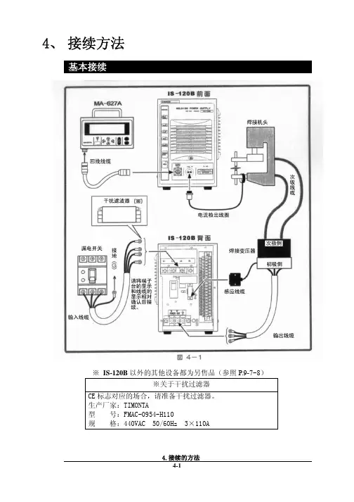
4、 接续方法基本接续※ IS-120B以外的其他设备都为另售品(参照P.9-7~8)※关于干扰过滤器CE标志对应的场合,请准备干扰过滤器。
生产厂家:TIMONTA型 号:FMAC-0954-H110规 格:440VAC 50/60Hz 3×110A接续步骤① 连接变压器请用输出电缆接续背面面板上的[焊接电源输出端子台]和焊接变压器的初级侧。
使用本公司的焊接变压器的场合请将信号电缆接续至[焊接变压器I/O信号]的接续接口上,连接焊接变压器。
使用其他公司的焊接变压器的场合请进行步骤⑤的作业。
② 连接电源用输入线缆(参照P.9-7)将焊接电源接续至背面面板的[焊接电源输入断路器]上。
请将PE端子接地。
③ 在[外部输入输出信号接续端子台]上接续必要的线缆。
请参照P.5-1准备接续用的线缆。
④连接编程操作器将回线线缆接续到正面面板的[编程操作器]接续接口上。
【使用其他公司的变压器的场合,请进行以下的操作】⑤ 连接次级电流检出用的检出线圈将检出线圈接续至正面面板的[检出线圈]接口上。
5、 接 口(1)外部输入输出信号的接续图外部输入输出信号端子台的规格额定电压 AC125V 以上耐电压 1200V 以上安装可能压着端子 最大2个压着端子尺寸 M3或M3.5(宽7.1)鼓励线缆截面积 端子No.1~5 →0.75mm 2以上 端子No.6~31→0.5mm 2以上*RY1~RY3规格型号G6B1114P(OMRON)线圈电压DC24V接点容量AC110V 0.5A(2)外部输入输出信号的说明(3)输入信号的接续方法电磁阀用电源输入为AC100V状态下使用的场合,请将1~5AC线和6~31的信号线分离后配线。
注意在下述①②③的使用场合,请根据用途接续附属的短路线。
在下述④的使用场合,请不要在6、7号接线柱上接续任何东西。
如果接续错误,会引起故障。
① 外部输入信号为接点输入的场合② 外部输入信号为接点输入的场合5. 接 口③ 外部输入信号为正COM输入的场合④ 外部电源供给输入的场合5. 接 口7、 时序图T1:[SCHEDULE]画面的[DELAY-START SET]中所设定的时间T2:约200ms(终了信号在起动信号处于ON状态期间或者200ms期间输出) T3:约80ms(此间不进行下次起动)8、 维护保养电池的更换本装置中使用的锂电池寿命为5年。
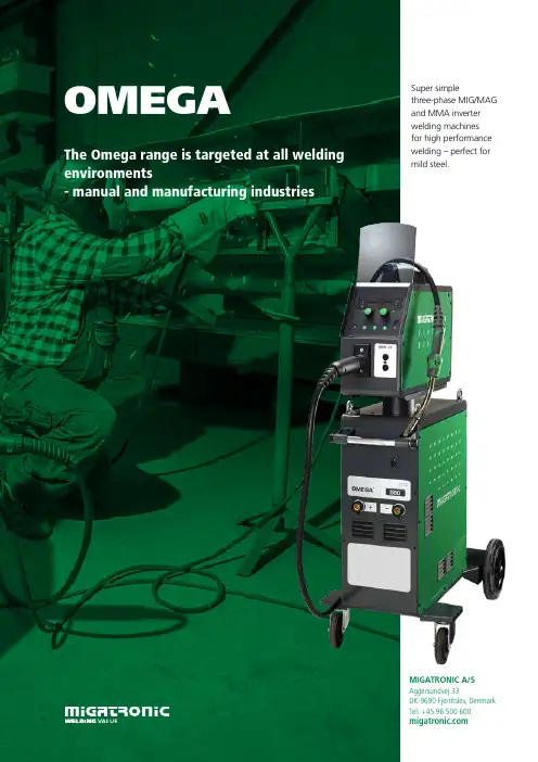
OMEGAMIGATRONIC A/S Aggersundvej 33DK-9690 Fjerritslev, Denmark Tel: +45 96 500 The Omega range is targeted at all welding environments- manual and manufacturing industriesSuper simplethree-phase MIG/MAG and MMA inverter welding machines for high performance welding – perfect for mild steel.THE OMEGA RANGE2EASE OF OPERATIONThe Omega range is available with three different control panels: Basic, Classic and Advanced. Basic and Classic are manual control panels by means of which you can operate the machine almost like a step-regulatedwelding machine, but they have all the advantages of an infinitely variable inverter. The Advanced control panel is synergic and features more than 70 versatile welding programs.FROM MIG/MAG TO MMA OR GOUGINGWith the Advanced control panel, the Omega is easy to change over from synergic MIG/MAG programs to MMA welding. Gouging is a standard feature in the Omega 550 with Advanced panel.POWERARC FOR THICK-WALLED PLATESThe program package for Omega 400 and Omega 550 with Advanced panel also includes PowerArc™ programs.OMEGA BOOST OR AUTOTRANSFORMERThe Omega 300 is available withelectronic Boost Converter (autotrans-former) for welding on all mono-phase and three-phase mains voltages. The Omega 400 and Omega 550 are available with a conventional autotransformer.REVERSED POLARITYAll Omega versions feature reversed polarity for welding with innershield wire (without gas).The MWF 27 wire feed unit is turn-able and detachable and equipped with four-roll wire feed system. Made of weather-proof reinforced aluminium, the wire feed unit is ideal for heavy-duty applications, and its control panel makes it easy to operate the welding machine on the welding site.The incorporated cooling system keeps the operating temperature in the torch low, irrespective of current load. This ensures trouble-free wire feeding and long life of wearing parts. The Omega 550S features double cooling and if combined with the FKS type of the MIG-A Twisttorch with a double cooling chamber, optimal comfort is provided under all operating conditions.Classic panel for manual control of the welding machine – including the advantages of the infinitely variable inverterBasic panel for manual setting of welding jobsAdvanced panel featuring e.g. PowerArc™ and DUO Plus™. DUO Plus provides a TIG-like weld appearance and better control of the weld pool. The panel con-tains programs for MIG brazing and welding using flux-cored or solid wires in mild and stainless steels and aluminium.The welding machines may be shownwith optional equipment.The Omega range includes three sizes of power sources: 300 A, 400 A and 550 A. The Omega 300 is available as an air-cooled C version (compact). The Omega 400 and 550 are available as air-cooled or water-cooled in C or S version with separate MWF 27 wire feed unit and replaceable interconnecting cables with quick-release fittings. IGC (Intelligent Gas Control) is an optional feature in all models, ensuring large-scale gas savings and optimal gas shielding in all current ranges.PowerArc ensures full penetration in fillet welds and butt welds and increased welding speed using mild and stainless steels.SUPER-SIMPLE MIG/MAG INVERTERS RANGING FROM 300 A TO 550 A3Welding in mild steel.A program reader is incorpo-rated in the Omega machines for easy software update via the SD card; the welding machines are designed to meet new requirements for materials and shielding gases.Omega 300 C Classic air-cooled and Omega 550 C Advanced water-cooled- both on trolleys.Omega 400 S-W with relief arm.SOFTWARE UPDATESAt you can download software for update of the Omega machines via the SD card.MIG-A TWIST ® - THE NEW GENERATION OF TORCHESThe ergonomic MIG-A Twist torch has a turnable swan neck for easy access to hard-to-reach locations. Control unit for adjustment of welding current at the torch handle is available as optional equipment.THE OMEGA RANGE4Dealer’s stamp:52173038Wire feed speed, m/min.1,5-27,0Wire spool diameter, mm 300Duty cycle 100%/40°C, A/%420 / 100Duty cycle 60%/40°C, A/%500 / 50Torch connection EURO Protection class IP23NormIEC60974-5, IEC60974-10 CL. A Dimensions (H x W x L), mm 470x210x690Weight, kg13We reserve the right to make changes.READ MORE AT • IGC ® Intelligent Gas ControlEXAMPLES OF EQUIPMENT:• IGC ® Intelligent Gas Control • Relief arm for S version • Current control unit• Push Pull kit (Omega 400/550)• Wheels and lifting bracket for MWF 27 (Omega 400S/550S)• Trolley for C version• Efficient cooling with or without flow control • Boost Converter (Omega 300)• Autotransformer 230-500 V (Omega 400/550)• CEE mains plug• Protective frame (Omega 300)•Gouging torch (Omega 550)OMEGA DATA。
焊接的基础知识一、精密电阻点焊使用金属材料制作零件的场合,有许多时候都需要将材料切断成规定的尺寸,再将其连接起来。
连接材料的方法有利用铆钉进行机械连接和利用焊接进行冶金连接以及利用超声波进行物理连接。
电阻点焊是利用冶金的方法将金属材料高效率地经济地连接起来的一种方法。
因此在产业界被广泛地使用。
我们将精密小型工件的电阻焊接称之为精密电阻点焊。
米亚基公司源源不断地开发出各种超小型、可高密度安装化的新型精密电阻点焊机,取代了以往的锡焊、铆接等金属连接工艺。
精密电阻点焊机是最适合用于小型的、性能要求高的电子部品,以及精密机械工业中的小型部品的组装。
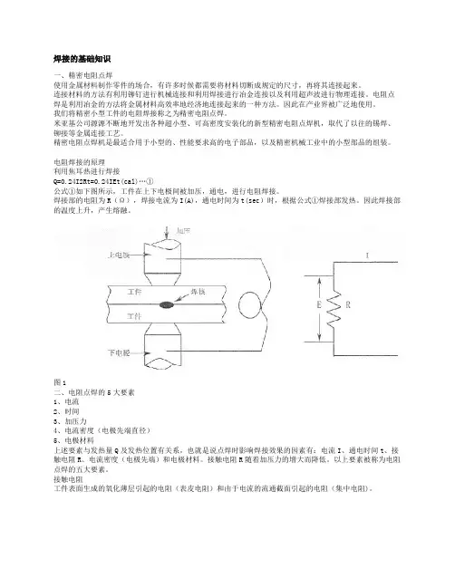
电阻焊接的原理利用焦耳热进行焊接Q=0.24I2Rt=0.24IEt(cal)…①公式①如下图所示,工件在上下电极间被加压,通电,进行电阻焊接。
焊接部的电阻为R(Ω),焊接电流为I(A),通电时间为t(sec)时,根据公式①焊接部发热。
因此焊接部的温度上升,产生熔融。
图1二、电阻点焊的5大要素1、电流2、时间3、加压力4、电流密度(电极先端直径)5、电极材料上述要素与发热量Q及发热位置有关系,也就是说点焊时影响焊接效果的因素有:电流I、通电时间t、接触电阻R、电流密度(电极先端)和电极材料。
接触电阻R随着加压力的增大而降低。
以上要素被称为电阻点焊的五大要素。
接触电阻工件表面生成的氧化薄层引起的电阻(表皮电阻)和由于电流的流通截面引起的电阻(集中电阻)。
图2上图中,R2,R4……材料自身的电阻;R3……上下工件之间的电阻;R1,R5,……电极与工件之间的电阻。
接触电阻是指R1、R3、R5。
三、电极的作用1.导通大电流。
2.施加压力。
3.提高焊接点的冷却效果。
4.稳定电流密度。
电极具有以上的作用,这里解释一下与品质管理有关的电流密度。
电流密度是指单位横截面中的电流值。
如果将电流密度一直保持稳定,就能防止焊接不良。
由于要导通大电流(电极作用1),电极顶端会发热;又由于要加压会使电极顶端变宽,电流密度变小,因此,随着焊接次数的增多,焊核会变小(焊接不良)因此在焊接品质管理中电极的管理(进行一定次数的焊接后更换或修磨电极)就变得非常的重要。
INSTRUCTION MANUALAUTOMIG XValid from 8647 50170005.CONTENTS:GENERAL DESCRIPTION (4)INITIAL OPERATING (5)CONTROL SWITCHES/INSTRUCTION (6)WELDING TECHNIQUE (7)MAINTENANCE (8)FAULTS (9)REPLACEMENT OF CONTROL UNIT (10)REPLACEMENT OF WIRE GUIDE LINER (11)TECHNICAL DATA (12)WELDING SCHEDULES (13)Only first-class materials have been used for the development and production of MIGATRONIC welding machines. The materials are subject to current control and quality supervison and then processed and mounted together into MIGATRONIC welding machines.No matter how good materials we have used and no matter how carefully the mounting has been done, an advanced product as a MIGATRONIC MIG-MAG-welding machine demands your effort to operate perfectly for years.Therefore study carefully this instruction before your initial operating. This should assure a profitable use of your new MIGATRONIC welding machine.CONGRATULATIONS!GENERAL DESCRIPTIONMIGATRONIC welding machines, type Automig: 140 Mono X, 140 X, 180 Mono X, 180 X, 185 X, 200 X, 250 X and 300 X have been developed for thin plate welding and car body repair.The Automig 140 Mono X and 180 Mono X are designed to normal single-phase 220-240 V plug (F+0+earth)/10 Amp(16Amp) where as the Automig 140 X, 180 X, 185 X, 200 X, 250 X, 300 X are designed for three-phase 220-380 V (3F+earth)/10Amp.Automig 185 X needs only two phase wires (2F+earth)/16Amp.The main parts of the machine are the main transformer, the contactor, the rectifier for welding current, the condenser battery (only 140 M X, 180 M X, 185 X), the control transformer, the wire feed motor, the solenoid valve and the electronic control.The welding transformer has been dimensioned to obtain optimum welding capacities, and for a working temperature of 180°C. For further protection a thermal fuse has been incorporated which automatically cuts out the machine at 150°C. The overheating protection will switch on automatically when the transformer has cooled. The rectifier is electronically protected against overloading in case of short circuit of the welding current, the machine will cut out after approx. 3 sec.Mode of operation: When the trigger at the welding handle is activated the contactor will couple voltage to the welding transformer which will give a secundary voltage decided by the position of the voltage switch. In the rectifier this AC voltage is transformed into a DC voltage which is applied between welding torch and return cable. At the same time the flow of protection gas and the wire feed motor are started. The number of revolutions is decided by the adjustment button. When you lift your finger from the trigger the motor will stop and after a short delay the contactor and the welding current are interrupted.This delay which is called "burn back delay" has the effect that the welding wire will burn back a little from the molten pool and thus does not stick to the pool. The time of delay can be set by the lowest trimpotentiometer at the print card.The electronic control can be set to the functions "seam" , "spot" , and "interval" .At "seam" the welding will start when you press the trigger and stop when you release the trigger.At "spot" the welding will stop after a delay that can be set by the button "welding time". Using this function you are sure of a uniform interval welding.In the position "interval" the wire feed motor will stop with intervals that can be set by the buttons "welding time" and "pause time". When you put "pauses" into the welding, the average heat volume added is reduced to prevent a burning through on difficult welding tasks.INITIAL OPERATINGMains connection:Input voltage should be as stated on the type plate of the machine. If dual voltage, the tapping must be checked before mains connection.Shielding gas connection:The shielding gas bottle is mounted on the machine and the regulator on the bottle. If the regulator is equipped with flowmeter, the gas quantity is adjusted on 5-15 litres/min.Welding hose connection:The welding hose is put through the hole in the front plate and into the switch on the wire feed console (see page 11). Keep the inlet nozzle as close to the wire feed roller as possible without letting them touch each other. Fasten the Allen screw and mount the gas hose and the control wire. Check that the hole in the inlet nozzle is in line with the groove of the wire feed roller.Fitting the welding wire:Turn the tension spring aside and tip it up. Check that the wire feed roller, the wire guide liner and the contact tip correspond to the wire diameter, the wire feed roller is designed for two wire dimensions and should be turned around until the outer side is showing the wire size being used. The following wire guide liner is recommendedWIRE DIAMETER FE.WIREmm WIRE GUIDE LINER INT.DIAM.mmø 0.6ø 0.8 - ø 1.0 ø 1.0 (ø 1.5)ø 1.5WIRE DIAMETER AL.WIREmm WIRE GUIDE LINER INT.DIAM.mmø 0.8 ø 1.0 ø 1.5 ø 1.5When using aluminium wire use a special guide liner where the internal liner goes all the way through the inlet nozzle. This prevents the aluminium wire from being damaged.The reel of wire is put on the hub, and the wire is put through the wire feed unit and some centimeters into the hose. As the wire guide liner is vulnerable to burrs at the point of the wire, it is important to file the point of the wire in order to remove all burrs and it is equally important to straighten out the first 10-15 cm. Unscrew contact nozzle. Tip up the lever. Set the wire speed at 6, press the start button, the wire runs through the hose. When the wire is through the hose, stop the machine and mount the contact nozzle. The pressure of the lever is adjusted to allow the wire feed roller just to slide on the wire when this is stopped at thecontact nozzle.Automig 185 XThe special welding hose is mounted at the quick clutch of the machine and the Jack-sleeve and the welding handle is mounted with the desired electrode holder.For planishing of dents with carbon the voltage switch of the machine shall be set at step 8 whereas voltage step 7 is used when welding nails or discs. Using this method it is important for a satisfactory result that you do not press the handle too hard against the workpiece as the contact resistance between nail (discs) and the piece is reduced and the desired generation of heat is decreased.You must also take care that the return clip is in good contact with the piece and is not attached too far from the welding point.CONTROL SWITCHES/INSTRUCTIONS1. Welding time: With this switch the welding time is chosen, when 2 is in position: interval and spot.2. Switch:Seam:The switch is set at seam. The trigger on the welding handle is activated, welding starts. By letting go the trigger you stop the welding process.Spot:The switch is set at spot. When the trigger on the welding handle is activated, welding starts. Welding automatically stops, depending on the time adjusted by button 1 (0.2-1.5 sec.)Interval:The switch is set at interval. When the trigger is activated, welding starts. The welding automatically stops, depending on the time adjusted by button 1. After an interval fixed at button 3 the same cycle continues automatically and is only interrupted when the trigger on the welding handle is released.3. Adjustable pausetime: With this button the pause time is chosen, when button 2 is in position: interval.4. Wire speed: With this button the wire feed speed is adjusted, depending on the welding voltage and wirediameter.Wire speed range: 2-12 m/min.5. Control lamp: Lights when the machine is on.6. Fuse7. Adjustment of welding voltage and main switch ON-OFF.8. Earth cable (only at Automig 185X).9. Connection for bolt welding hose (only at Automig 185 X).10. Pilot cable for bolt welding hose (only at Automig 185 X).WELDING TECHNIQUESetting of the machineThe setting of a MIG-MAG welding machine demands some practice from the welder, the machine having two control points that have to conform. These two are the wire feed speed and the welding voltage. The welding current is determined by the wire feed speed, and it should correspond to the workpiece. The current will increase with increased wire speed, resulting in a shorter arc. Less wire speed will reduce the current and lengthen the arc. Increasing the welding voltage hardly alters the current intensity, but lengthens the arc. By decreasing the voltage a shorter arc is obtained with little change in current intensity.When using CO2 as shielding gas, increase the voltage by about 5 Volts per 100 Amp.When changing the wire diameters, different control settings are required. A thinner wire needs more speed to acquire the same current strength. A satisfactory weld cannot be obtained if extreme values are exceeded.If the feed speed is too high for the welding voltage, blockage will occur in the torch as the wire dips into the molten pool and does not melt. Welding in these conditions normally gives faults due to lack of fusion. If, however, the welding voltage is too high, large drops will form on the end of the wire, causing spatter.The correct setting of voltage and speed can be seen in an even and calm arc.See tables.Influence of the welding positionThe position of the torch and the work piece is important for the quality and appearance of the seam.The diagrams on the next page show some of the many possibilities and indicate schematically the importance of these positions. In practice one of course uses all combinations of welding positions, torch directions and positions of the work piece.Together with the figures, the diagram below may help when an estimation of the importance of separate factors for welding quality is needed.The terms drawing weld and thrusting weld mean:Drawing weld:torch sloped in direction of weldThrusting weld:torch sloped away from direction of weld.Drawing weld is sometimes designated "dragging welding" and thrusting weld "stabbing" weldingThrusting weld Drawing weldWidth of seam wider narrowerUpper bead smaller largerPenetration decreaseincrease Tendency to lack of fusion greater lesserMAINTENANCEThe following items demand special attention:Wire feed unitThis unit is to be checked regularly at the wire feed roller and the wire nozzles, as it is of great importance for a satisfactory welding result and a minimum of wear and tear that the wire passes through the mechanism without any deformations of the wire or the wire feed roller.The wire nozzles should often be checked and changed if the copper coating of the wire is damaged on its way through the nozzles. Copper dust may totally hinder free passage through the wire liner.A weekly check and cleaning of the nozzles as well as the wire feed roller is recommended.Welding hoseGreat care should be taken that the welding hose is not overloaded. It should not be pulled over sharp edges, and other heavy machines should not run over it as it may damage the wire lines. The hose should be dismantled every week and blown out with dry air.Welding torchThere are many parts in the welding torch that have to be cleaned regularly. The main ones are the contact tip and the gas nozzle. During the welding process, these parts are bombarded with spatter that sticks in the nozzles. This may disturb the shielding gas flowing from the gas nozzle down to the molten pool. Otherwise, if the gas nozzle is blocked up with spatter, there is a danger that a short-circuit will occur between the contact tip and the gas nozzle. The spatter should therefore be removed regularly and spatter remover applied in order to prevent spatter from burning into the nozzles. During the cleaning process, the gas nozzle should be removed.DO NOT CLEAN BY BEATING THE TORCHPower sourceThe rectifier and transformer should be blown out with dry air occasionally, otherwise the air circulation will be affected by the dust.FAULTSFAULT:Too little welding effectThe welding seam forms a bead. PROBABLE CAUSE:1. One of the three fuses in the main switch is notworking (one phase is missing).2. The welding voltage is too low.Switch one setting higher.The wire feed is blocking. 1. The inlet nozzle and the wire are not in alignmentwith each other.2. The reel of wire is too taut, the wire must come offthe reel evenly.3. The inlet or contact tip is worn out or is blocked up.4. The welding wire is not clean or it is rusty. It couldalso be of an inferior quality.5. The pressure roller has to be tightened.Spatter 1. The wire feed is too fast for the voltage setting.2 Worn out contact tip.Porous weld.A cone is formed when spot welding 1. Insufficient gas - not enough pressure or the bottleis empty.2. Contact tip is blocked up.3. Leakage - air is pumped in and mixes with theshielding gas.The arc does not look normal, and there is a lot ofspatter1. The material is dirty, underseal or paint.The wire keeps sticking in the contact tip and is very slow 1. The wire can be malformed.The damaged wire should be cut off, pulled outand replaced. The pressure on the wire feed roller should be checked.2. Worn out contact tip.No welding voltage 1. Working voltage interrupted due to overloading ofthe transformer. Automatic switch on after cooling(15-30 min.).REPLACEMENT OF CONTROL UNIT1. Switch off current.2. Remove buttons on the front plate.3. Remove side panel.4. Disconnect multiplug outlets and unscrew the nuts.5. Dismount potentiometer for pause time.6. Pull out control unit.7. Mount the new control unit inversely.8. Do not connect the machine before the multiplug is in the right place.NutNutPlugREPLACEMENT OF WIRE GUIDE LINER1. Unscrew the Allen screw, disconnect the gas hose and the control wire, pull out the welding hose.2. Dismount the welding torch.3. Unscrew the Allen screw for fixing the wire guide liner. The nozzle to which the wire guide liner has beenfixed can now be pulled out to the rear.4. Push in the new wire guide liner. During the mounting the hose should be in as straight a line as possible.5. Press home the nozzle and screw the Allen screw for fixing the wire guide liner.6. Cut the liner so that it is in line with the outer edge of the connection nipple. If the wire guide liner is ofplastic, cut it with a sharp knife.7. Mount the welding torch.8. Connect the welding hose as explained page 5.Gas hoseAllenscrewControl wireTECHNICAL DATA140 MX 180 MX 185 X 140 X 180 X 200 X 250 X 300 X Mains voltage 50 Hz 1x220V 1x220V 1x380V 3x380V 3x380V 3x380V 3x380V 3x380V Mains voltage 50 Hz 1x240V 1x240V 1x415V 3x415V 3x415V 3x415V 3x415V 3x415V Mains voltage 50 Hz 1x220/380V 3x220/380V 3x220/380V 3x220/380V 3x220/380V3x220/380V10A 16A 25A 10A 16A 16A 16A 25A Fuse220/240V380/415V 16A 10A 10A 10A 10A 16A FuseConsumption max. 2.6 kVA 6.3 kVA 5.3 kVA 3.5 kVA 4.5 kVA 6.2 kVA 9.2 kVA 12.2 kVAEfficiency 0.85 0.85 0.85 0.85 0.85 0.85 0.82 0.82 Cos. phi. 0.90 0.95 0.92 0.89 0.85 0.87 0.87 0.87Open circuit voltage 20-31V 20-36V 19-36V 18-25V 17-31V 15-31V 15-37V 16-44V100%cycle50A 60A 65A 45A 65A 95A 145A 165A duty1260% duty cycle 60A 80A 85A 60A 85A 125A 185A 210A 35% duty cycle 80A 100A 110A 75A 110A 160A 220A 260A 25% duty cycle 250A 300A20% duty cycle 200A15% duty cycle 140A 180A 180A 115A 180ACurrent range 25-140A 25-180A 25-180A 25-140A 25-180A 25-200A 25-250A 25-300A4 6 6+2 4 7 10 10 10adjustmentVoltageAvailable for other mains voltagesTABLES FOR SETTING OF THE MACHINEThese tables are only intended as a guide, as the datas may change depending on the length of the arc, the torch handling and the position of the welding seam.Furthermore, the values change if the mains voltage is appreciably above or beneath 380V (220V). The values are based on CO2 shielding gas.When welding with mixed gas as shielding gas, wire speed should be increased by about 10 or welding voltage should be decreased by about 10 (1-2 steps).SEAM- AND INTERVAL WELDING SPOT WELDING0.6 mm0.8 mm 1.0 mm0.8 mmMaterial thickness mm WeldingvoltagesettingWirespeedWeldingvoltagesettingWirespeedWeldingvoltagesettingWirespeedMaterialthicknessmmWeldingvoltagesettingWirespeedWeldingtime140 MX0.5-11-22-33-42-45-82-33-42-33-4.5180 MX0.5-11-22-42 3-42-3.54-52-33-452-33-3.580.5+0.51+155-655-70-51-2185 X0.5-11-22-4 2-33-42-3.53.5-52-33-45-62-33-45-70.5+0.51+155-655-70.51-2140 X0.5-11-2 1-23-43-55-623-42.5-3.53.5-4.0180 X0.5-11-22-4 3-45-62.5-3.56.5-8.53-44-55-72-33-4.54.5-6.50.5+0.51+1777-87-912-4200 X0.5-11-22-44-62-34-53-44-62-33-55-77-92-33-44-6.56.5-100.5+0.51+19107-8100.81250 X0.5-11-22-44-61-34-52-34-62-33-55-67-102-33-44-76-102-33-45-67-90.5-11-22-33-40.5+0.51+18978-100.81。
米亚基焊机参数说明1.电源参数:-电压:米亚基焊机通常支持220V的电压,但也有一些型号支持110V或380V的电压。
-频率:通常为50-60Hz。
2.输出功率参数:-输出电压:米亚基焊机的输出电压范围通常为20V-40V,可以通过调节来适应不同的焊接需求。
-输出电流:米亚基焊机的输出电流范围通常为10A-200A或更高,可以根据不同焊接材料和厚度进行调节。
3.焊接参数:-焊接方式:米亚基焊机支持多种焊接方式,如手工弧焊、脉冲焊、TIG焊、MIG/MAG焊等。
-焊接材料:米亚基焊机适用于焊接各种金属材料,如碳钢、不锈钢、铝合金等。
- 焊接厚度:米亚基焊机适用于不同焊接厚度的金属材料,通常可以焊接1mm以上的薄板,也可以焊接几十毫米的厚板。
4.焊接控制参数:-焊接电流调节:米亚基焊机通常具有电流调节功能,可以根据需要调整输出电流,以适应不同焊接任务的要求。
-焊接时间设定:米亚基焊机通常具有焊接时间设定功能,可以设定焊接时间,以提高焊接质量和效率。
-焊接模式选择:米亚基焊机通常具有多种焊接模式可选择,如手动焊接、自动焊接等,以适应不同的使用场景和需求。
5.安全保护参数:-过载保护:米亚基焊机通常具有过载保护功能,当焊接电流超过设定范围时,会自动切断电源,以防止设备过载损坏。
-过热保护:米亚基焊机通常具有过热保护功能,当设备温度过高时,会自动停止工作,以防止设备过热损坏。
-过流保护:米亚基焊机通常具有过流保护功能,当输出电流超过设定范围时,会自动切断电源,以保护设备和焊接件的安全。
总之,米亚基焊机是一种多功能、高效、安全可靠的电焊机,适用于各种焊接任务,并具有多种参数调节和安全保护功能,能够满足用户的不同需求。
1.注意事项2.特点:3.各部名称及功能⑴显示面板显示焊接规范的设定、焊接电流监测等信息。
⑵START指示灯输入启动信号,时序启动后的持续时间内灯亮。
⑶电源指示灯POWER将电源开关置于ON,供给电源,装置正常动作时灯亮。
⑷READY指示灯处于可以导通焊接电流的状态时灯亮。
必要条件:1.WELD灯点亮;2.背面端子台的WELD ON/OFF端子处于闭路状态。
⑸TROUBLE指示灯发生异常情况时点亮。
(可按RESET复位键消除)⑹WELD指示灯不导通焊接电流,只启动时序使用该键。
⑺方向键CURSOR使显示画面上的光标左右上下移动。
⑻菜单键按下MENU键显示菜单选项。
⑼复位位当显示异常情况时,在排除异常原因后按该键显示复位。
⑽确认键确认设定值和选择项目时使用该键。
⑾+键按该键,所需变更的项目值增大。
⑿-键按该键,所需变更的项目值减小。
⒀电源键置于ON时导通电源。
4.画面说明⑴菜单画面MENU按MENU键,显示菜单画面。
将光标移动到指定的项目,按下ENTER键,则变为所选中的画面。
⑵规范设定画面SCHEDULE设定规范(焊接规范)的画面。
将光标移动至要变更的数值上,按+键或-键,达到所希望的数值后按ENTER键,完成设定。
⑶焊接结果监测画面MONITOR显示焊接时的电流、电压、功率、电阻的测定值的画面。
按△键或▽键,改变显示项目。
判定为“良”的焊接次数;若要归零,请短路控制信号端子台18-19号。
⑷监测值设定画面COMPARATOR设定电流、电压、功率的上限值和下限值也称监测值。
测定值如果在设定的监测值范围内则被判定为“良”,否则为“不良”。
⑸预检查画面PRECHECK设定检查通电的通电时间和控制电压的画面。
在正式通电之前,以定电压控制方式导通小电流,根据此时所测定的电流值来检查被焊接工件是否设置正确。
按+键或-键,达到所希望的数值后按ENTER键,完成设定。
⑹功能设定画面STATUS变更装置的初始设定的画面,请根据使用环境进行详细设定。
米亚基焊接控制器简要说明一.控制器面板图1.米亚基CY-210横置焊接控制器2.米亚基CT-110竖置焊接控制器二.操作面板功能简要介绍下面以CT-110的控制器做介绍。
1.米亚基焊接控制器主要特点:1)面板用LED显示焊接电流、焊接规范编号、焊接时间等。
2)可以记忆15种不同材质、板厚工件的焊接规范。
3)3段通电方式,具有电流缓升、缓降功能。
4)采用初级、次级定电流反馈控制方式、电源电压变动补偿方式等3种控制方式,可保证提供稳定的焊接电流。
目前米亚基的焊接控制器均使用次级定电流反馈控制方式。
5)有电流、通电角监控功能。
6)利用通电时序信号,进行焊接互锁。
7)防油、防尘面板保护罩。
8)3组计数器(可记录焊接打点数及生产量等)。
2.米亚基焊接控制器面板1)焊接通道选择按(条件输入NUMBER)以切换15种焊接规范每按动条件入力一次,通道编号自动增加1,超过15则回到1。
持续按动,则连续变化。
2)状态指示灯溶接电源灯亮表示380V电源已经OK,异常灯亮时表示焊接有异常启动输入亮时为焊接控制器焊接过程启动中溶接可能灯表示可以进入焊接放电状态(焊接允许)电流注意CAUTION灯表示焊接电流状态异常。
可通过异常复位消除。
STEP END 灯打点数到3)焊接参数设置SQ :预压C2 :冷却ⅡW1 :焊接ⅠW3 :焊接ⅢC1 :冷却ⅠS2 :缓降ⅡS1 :缓升Ⅰ(提高)HO :加压保持W2 :焊接ⅡOF :重复焊接次数其中S1、W2、S2均为对应焊接Ⅱ。
设置方式为右箭头每按一次SQ~OF的红灯依次向右移一格。
右侧的显示框显示为该设定阶段的设定值(单位为周波数(对应日常50Hz电源为1秒钟为50个周波))下部电流显示框可设置、显示最大99.9KA电流。
数据的输入可按+、-键进行操作4)监控状态当+%和-%键同时按亮时监控显示值为最大电流。
当按亮通电角时处于监控状态时显示焊接时的焊接电流导通角。
当数值接近180时说明焊接的状态不佳应该检查下导电铜带焊接夹具的各处铜带铜夹具导电状态。
焊接的基础知识一、精密电阻点焊使用金属材料制作零件的场合,有许多时候都需要将材料切断成规定的尺寸,再将其连接起来。
连接材料的方法有利用铆钉进行机械连接和利用焊接进行冶金连接以及利用超声波进行物理连接。
电阻点焊是利用冶金的方法将金属材料高效率地经济地连接起来的一种方法。
因此在产业界被广泛地使用。
我们将精密小型工件的电阻焊接称之为精密电阻点焊。
米亚基公司源源不断地开发出各种超小型、可高密度安装化的新型精密电阻点焊机,取代了以往的锡焊、铆接等金属连接工艺。
精密电阻点焊机是最适合用于小型的、性能要求高的电子部品,以及精密机械工业中的小型部品的组装。
电阻焊接的原理利用焦耳热进行焊接Q=0.24I2Rt=0.24IEt(cal)…①公式①如下图所示,工件在上下电极间被加压,通电,进行电阻焊接。
焊接部的电阻为R(Ω),焊接电流为I(A),通电时间为t(sec)时,根据公式①焊接部发热。
因此焊接部的温度上升,产生熔融。
图1二、电阻点焊的5大要素1、电流2、时间3、加压力4、电流密度(电极先端直径)5、电极材料上述要素与发热量Q及发热位置有关系,也就是说点焊时影响焊接效果的因素有:电流I、通电时间t、接触电阻R、电流密度(电极先端)和电极材料。
接触电阻R随着加压力的增大而降低。
以上要素被称为电阻点焊的五大要素。
接触电阻工件表面生成的氧化薄层引起的电阻(表皮电阻)和由于电流的流通截面引起的电阻(集中电阻)。
图2上图中,R2,R4……材料自身的电阻;R3……上下工件之间的电阻;R1,R5,……电极与工件之间的电阻。
接触电阻是指R1、R3、R5。
三、电极的作用1.导通大电流。
2.施加压力。
3.提高焊接点的冷却效果。
4.稳定电流密度。
电极具有以上的作用,这里解释一下与品质管理有关的电流密度。
电流密度是指单位横截面中的电流值。
如果将电流密度一直保持稳定,就能防止焊接不良。
由于要导通大电流(电极作用1),电极顶端会发热;又由于要加压会使电极顶端变宽,电流密度变小,因此,随着焊接次数的增多,焊核会变小(焊接不良)因此在焊接品质管理中电极的管理(进行一定次数的焊接后更换或修磨电极)就变得非常的重要。
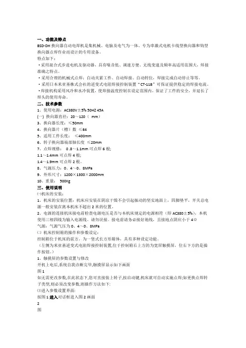
DG6焊机参数可修改范围,如图所示:
于是定电流焊机方式,所以焊接电压VOLT和功率POWE对焊接无影
第一段焊
接电流注:请勿设置第二段焊接时间及焊接电流,
接,所以请保持COOI和WE2时间为0ms
由于该焊接
不要随意更改其参数;
请勿更改
HOLD 100
士
保持时间焊接电流结束后保持时间s
段电流焊第一段电流上升时间斜度UP SLOPE 15 士5ms
焊接停止控制WELD STOP:于是时间控制焊接电流通断,所以第一第一段焊
接停止控段控制TN
制
焊接时间WELD TIME上限HI,下限LOW根据需要设置
焊接深度判断COM:上限HI,下限LOW根据需要设置。
WORK DETECTDELAY TIME 保持默认值。
注:由于是一段焊接,请勿对第二段焊接WE2参数进行修改。
除以上各个画面参数外,其余未作说明画面的参数请保持默认值,要随意修改。