PREC软件功能介绍及其在预应力混凝土结构设计中应用
- 格式:ppt
- 大小:5.30 MB
- 文档页数:78
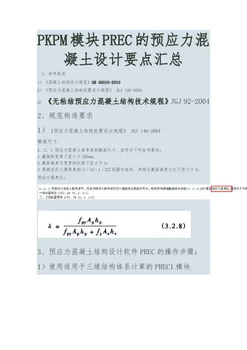
PKPM模块PREC的预应力混凝土设计要点1、参考规1)《混凝土结构设计规》GB 50010-20102)《预应力混凝土结构抗震设计规程》JGJ 140-20043) 《无粘结预应力混凝土结构技术规程》JGJ 92-2004 2、规构造要求1)《预应力混凝土结构抗震设计规程》JGJ 140-2004截面尺寸:4.2.1 预应力混凝土框架粱的截面尺寸.宜符合下列各项要求:1 截面的宽度不宜小于250mm;2 截面高度与宽度的比值不宜大于4;3 梁高宜在计算跨度的(1/12~1/22)围选取.净跨与截面高度之比不宜小于4。
预应力强度比:3、预应力混凝土结构设计软件PREC的操作步骤:1)使用适用于三维结构体系计算的PREC1模块2、3、《混凝土结构设计规》4、自动布置预应力筋5、存盘退出6、7、8、9、计算后调整预应力线型10、调整预应力钢筋线形的技巧初始设计时,我对预应力混凝土梁仅指定了型号为1的四段抛物线型,计算后程序提示线形不合理,根据上述技巧,我对预应力混凝土梁同时指定了型号为1的四段抛物线型+型号为3的两段折线型,如下:重新计算后,程序不再有警告信息了,说明线形合理了。
发现预应力梁跨中底部裂缝宽度为1.159,大于裂缝限值0.2,需加大梁底纵向钢筋。
将预应力梁底纵筋连通(按最大配)再次验算裂缝,发现变小了,但仍然超过限值0.2;继续修改钢筋,如下:一味地增加梁底普通纵筋,对裂缝宽度控制效果不好,建议此时调整预应力线形形式或增加预应力钢筋。
我增加了预应力钢筋,由原来的每种型号13根增加为每种型号25根,发现裂预应力度均满足规,梁底受压没有产生裂缝,说明预拉过头。
我调整预应力线形形式,将其中的2号直线形式集中荷载作用点位置移动值预应力梁的中间(原先在1/3处),发现梁底裂缝满足要求;不过查看梁底纵筋,发现变为22d25,配筋率为1.5%。
此时,发现本工程框架抗震等级为3级,规规定的预应力度限值为0.75,预应力梁左端上部为1.014,需降低。
PKPM模块PREC的预应力混凝土设计要点1、参考规范1)《混凝土结构设计规范》GB 50010-20102)《预应力混凝土结构抗震设计规程》JGJ 140-20043) 《无粘结预应力混凝土结构技术规程》JGJ 92-2004 2、规范构造要求1)《预应力混凝土结构抗震设计规程》JGJ 140-2004截面尺寸:4.2.1 预应力混凝土框架粱的截面尺寸.宜符合下列各项要求:1 截面的宽度不宜小于250mm;2 截面高度与宽度的比值不宜大于4;3 梁高宜在计算跨度的(1/12~1/22)范围内选取.净跨与截面高度之比不宜小于4。
预应力强度比:3、预应力混凝土结构设计软件PREC的操作步骤:1)使用适用于三维结构体系计算的PREC1模块2、3、《混凝土结构设计规范》4、自动布置预应力筋5、存盘退出6、7、8、9、计算后调整预应力线型10、调整预应力钢筋线形的技巧初始设计时,我对预应力混凝土梁仅指定了型号为1的四段抛物线型,计算后程序提示线形不合理,根据上述技巧,我对预应力混凝土梁同时指定了型号为1的四段抛物线型+型号为3的两段折线型,如下:重新计算后,程序不再有警告信息了,说明线形合理了。
发现预应力梁跨中底部裂缝宽度为,大于裂缝限值,需加大梁底纵向钢筋。
将预应力梁底纵筋连通(按最大配)再次验算裂缝,发现变小了,但仍然超过限值;继续修改钢筋,如下:一味地增加梁底普通纵筋,对裂缝宽度控制效果不好,建议此时调整预应力线形形式或增加预应力钢筋。
我增加了预应力钢筋,由原来的每种型号13根增加为每种型号25根,发现裂预应力度均满足规范,梁底受压没有产生裂缝,说明预张拉过头。
我调整预应力线形形式,将其中的2号直线形式集中荷载作用点位置移动值预应力梁的中间(原先在1/3处),发现梁底裂缝满足要求;不过查看梁底纵筋,发现变为22d25,配筋率为%。
此时,发现本工程框架抗震等级为3级,规范规定的预应力度限值为,预应力梁左端上部为,需降低。

预应力筋束形设计及PREC软件应用范美玲;邵光信【期刊名称】《建筑结构》【年(卷),期】2006(0)S1【摘要】预应力混凝土结构不仅使混凝土材料的名义抗拉强度得到极大的提高,同时使得高强度预应力筋的强度得到充分利用,因而其节材效果好,结构性能好,得到了广泛的推广应用。
PREC软件作为预应力混凝土结构的专用设计软件得到了设计人员的认可和积极应用,并创造了许多优秀的预应力混凝土结构。
迄今为止国内外任何一个预应力软件都要求使用者首先假定预应力筋的束形,软件只能根据假定的束形和张拉力进行预应力各项计算。
事实上良好的束形设计不仅可以加快设计速度,更能降低预应力筋用量,并提高预应力混凝土结构的性能。
如果束形假定不当,不仅得不到好的设计结果,往往容易造成材料的浪费,甚至出现设计错误。
所以理解不同束形的张拉效应特点,并根据结构特点合理假定预应力筋束形是十分重要的,也是设计人员需要完成的重要工作。
结合PREC软件的应用,介绍了预应力筋束形设计原理及工艺构造要点。
【总页数】4页(P551-553)【关键词】预应力筋束形;预应力效应;束形参数;构造;软件应用【作者】范美玲;邵光信【作者单位】中国建筑科学研究院PKPMCAD工程部【正文语种】中文【中图分类】TU378;TU311.41【相关文献】1.不同束形配筋的预应力混凝土受扭梁的实验研究 [J], 刘晚成;葛小民;左洪亮;陈亭2.CFRP筋作体外预应力束的简支梁桥设计研究 [J], 王鹏;丁汉山;丁如珍;李浩;王新定3.预应力混凝土连续梁底板连续钢束锯齿块配筋设计探讨 [J], 陈开利;王解元4.无粘结预应力砼平板结构中预应力筋布束方式的探讨 [J], 王友权;荣文广5.金马大桥主塔直束预应力筋设计技术与研究分析 [J], 余报楚;张哲;张洪金因版权原因,仅展示原文概要,查看原文内容请购买。
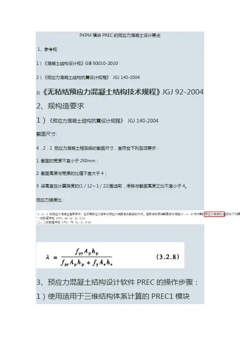
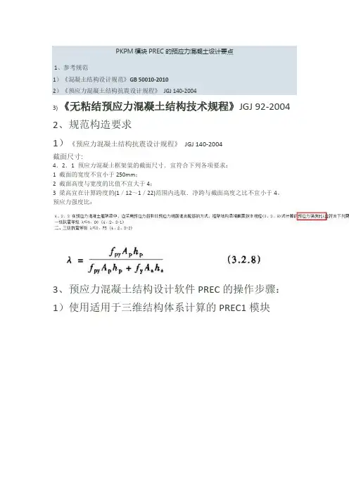
PKPM模块PREC的预应力混凝土设计要点汇总1、参考规范1)《混凝土结构设计规范》GB 50010-20102)《预应力混凝土结构抗震设计规程》 JGJ 140-20043) 《无粘结预应力混凝土结构技术规程》JGJ 92-2004 2、规范构造要求1)《预应力混凝土结构抗震设计规程》 JGJ 140-2004截面尺寸:4.2.1 预应力混凝土框架粱的截面尺寸.宜符合下列各项要求:1 截面的宽度不宜小于250mm;2 截面高度与宽度的比值不宜大于4;3 梁高宜在计算跨度的(1/12~1/22)范围内选取.净跨与截面高度之比不宜小于4。
预应力强度比:3、预应力混凝土结构设计软件PREC的操作步骤:1)使用适用于三维结构体系计算的PREC1模块2、3、《混凝土结构设计规范》4、自动布置预应力筋5、存盘退出6、7、8、9、计算后调整预应力线型10、调整预应力钢筋线形的技巧初始设计时,我对预应力混凝土梁仅指定了型号为1的四段抛物线型,计算后程序提示线形不合理,根据上述技巧,我对预应力混凝土梁同时指定了型号为1的四段抛物线型+型号为3的两段折线型,如下:重新计算后,程序不再有警告信息了,说明线形合理了。
发现预应力梁跨中底部裂缝宽度为1.159,大于裂缝限值0.2,需加大梁底纵向钢筋。
将预应力梁底纵筋连通(按最大配)再次验算裂缝,发现变小了,但仍然超过限值0.2;继续修改钢筋,如下:一味地增加梁底普通纵筋,对裂缝宽度控制效果不好,建议此时调整预应力线形形式或增加预应力钢筋。
我增加了预应力钢筋,由原来的每种型号13根增加为每种型号25根,发现裂预应力度均满足规范,梁底受压没有产生裂缝,说明预张拉过头。
我调整预应力线形形式,将其中的2号直线形式集中荷载作用点位置移动值预应力梁的中间(原先在1/3处),发现梁底裂缝满足要求;不过查看梁底纵筋,发现变为22d25,配筋率为1.5%。
此时,发现本工程框架抗震等级为3级,规范规定的预应力度限值为0.75,预应力梁左端上部为1.014,需降低。
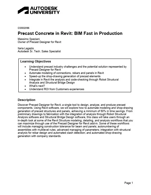
CS502096Precast Concrete in Revit: BIM Fast in Production Massimo SpezianiOwner of Precast Designer for RevitIlaria LagazioAutodesk Sr. Tech. Sales SpecialistDescriptionDiscover Precast Designer for Revit, a single tool to design, analyze, and produce precast components. Using Revit software, we will explore how to automate modeling and shop-drawing generation of precast structures and panels, achieving a minimum of 50% in time savings. From preliminary drawings to fabrication with the integration of analysis through Robot Structural Analysis software and Structural Bridge Design software, this class will take users through anin-depth look at some of the Revit Structure modeling, detailing, and analysis workflows that you can maximize through use of the Precast Designer for Revit add-in. Some of these workflows will include managing construction tolerance for beam and panels; autonumbering of assemblies with multilevel rules; advanced managing of parameters; integration with structural analysis for rebar design and automated clash detection; and automated shop-drawinggeneration with company standards.Speaker(s)Massimo SpezianiHe is the owner of “Precast Designer for Revit” a single tool to design andanalyze precast structures. He has a structural engineering background andworks as software developer providing Revit, Robot and Forge developmentservices. Massimo holds a master’s degree in structural engineering fromUniversity of Brescia, Italy.Ilaria LagazioAfter graduation in Structural Engineering at University of Genoa, Ilaria startedto operate in construction industrialization as Building System DevelopmentManager, focusing on the flow of data from the model to the construction siteThis interest for industrialized buildings brought her to a field experience inUAE and then to Autodesk where, with an industry experience of more than 20years, she covers the role of AEC Senior Technical Sales SpecialistUnderstand precast industry challenges and the potential solution represented by Precast Designer for RevitStructure is the skeleton of the building as it transfers loads to the earth and because of its importance it takes a consistent part of money and efforts. It is the first part of the building that must be built, so it is in the critical path of the AEC design and construction. Prefabrication, industrialized construction, AEC and Digital manufacturing convergence are becoming more and more important at worldwide level. Structural prefabrication is increasing worldwide expected to reach $125.46 billion in 2026 at a CAGR of 5.57%, making it a critical part of project delivery.Figure 1. Precast Concrete WorldwideIn detail, concrete is a dominant material for construction and in many parts of the world the cost of steel that is raising higher and higher could help to increase this trend.Structural Industry PersonasIn this paragraph we look at the personas/roles and the workflow that is typical of structural engineering.Figure 2. Typical engineering workflowIn one side of the above image, we have a designer that could be a structural engineer with one or more structural designers; they are in charge of defining how the structure should be created in order to support the loads and how it should be built in a general way.In the other side we have what we call the Detailers: for precast or for steel, they are the ones which create the details of the structure and rebars, components, steel elements that should be fabricated.Sometimes Detailers come from the fabrication company. This is theoretical scheme, we know very well that these roles sometimes are not covered by different people, but one person can cover more than one role, and this also depends on country or region-specific cases. Anyway, having all these people or not, does not change the fact that these “roles” need to exchange information and setup a workflow to exchange information.Current challenges in precastTraditionally we have challenges, that are quite recurring in different areas and sub industries. And these are the challenges that we will try to face in this white paper. The main challenges in the precast industry are:•Material waste and delays on the jobsite•Increasing project complexity•Hiring and retaining skilled workforce•Increase degree of standardization inside the company•High variability of precast production components•Design, analysis, and production disconnection.BeforeWhatever is the kind of structure we have a modeling phase, a documentation phase, and an analysis phase.Figure 3. Current typical workflowThere is a workflow and a possibility to connect data between different Autodesk software. For example, there is a direct bidirectional connection between Revit and Robot, and we have a lot of automation added through Dynamo. We also have the possibility to use Structural Bridge design, even if we can notice here that we do not have a direct connection between Revit a Structural Bridge Design. What is the scope of Precast Designer for Revit?NowTo avoid errors due connected or not connected data in different software and in order to automate the process from modeling to analysis and code-checking we have developed Precast Designer for Revit.Figure 4. Process integration in Revit with Precast DesignerPrecast designer for Revit is not a traditional link, bridging data from one software to the other. It is unique interface on top of Revit with all the other activities (calculation / analysis) integrated and running in background. So, the user has one single interface (Revit) where he has all the information needed and all the flexibility needed. Using Revit as a single platform the user can design, analyze, and produce precast components from modelling to fabrication with the integration of analysis tools.Also, this unique interface can be adapted for different kind of structures because it is based on Revit generic families. And a new precast component with its behaviour does not need a software developer to be added to the production library.Key Features of Precast DesignerPrecast Designer was designed in the last 3 years with in mind flexibility and simplicity. We can talk of the three main groups of functionalities: modeling, documentation, and analysis.Figure 5. Groups of functionalitiesAbout modeling: this is an important part of the process. There are at least 5 features to speed up modeling and reduce errors:•Automatic connections between elements•Automatic check of construction tolerance for elements and panels•Segmentation of panels and creation of construction model•Modeling of rebars and strands directly in families•Multi-level marking.The second part is about the documentation. Some features for speed-up documentation generation are:•Automatic shop drawings for every Revit element•Semi-automatic dimensions for general views•Bidirectional link with Excel and one directional with Word•Advanced data management•Profile view for infrastructures projects.The third part is about analysis. The software can drive Robot in the background and Bridge Design to perform the calculation of the structure and the code checking of concrete elementsusing real reinforcement in Revit. The results of the analysis are saved in Revit and a custom calculation report can be created. Main features for analysis are listed below:•Extended Integrated Analysis with Robot Structural Analysis•Code Checking of Concrete Panels and Members with Structural Bridge Design•Save Code Checking Results in Revit as Maps•Customizable Calculation Reports.It would be an epic novel of more than 1000 pages to explain all the features. In the next chapter there is general overview of the application of this workflow by looking at some real projects.Figure 6. Example project realized with the software - Courtesy of Magnetti BuildingAutomate modeling of connections, rebars and panels in RevitIn this chapter we will explain some of the main features to speed-up modeling and reduce errors.CorbelsPlacing corbels could be done automatically. Multiple corbels at different elevations could be placed at the same time. The corbel width could be adapted automatically by the software to the effective column width based on user rules.Figure 7. Automatic place corbels on columns - Courtesy of Magnetti Building ConnectionsCreating connections between elements is generally a time-consuming task.Figure 8. User connection rules - Courtesy of Magnetti BuildingPrecast designer can create connections between columns, beams and panels using user families. Families can be hosted or not hosted. It can drive the parameters of the connections based on the rules defined by the user and saved on to an external database.Figure 9. Automatic connections - Courtesy of Magnetti BuildingSometime, if the engineers are facing big projects, they need to split the model in parts or lots. The software can create connection of elements also in linked model. The logic of application of one type of connection can be a function of geometry or data of connected elements.Rebars and StrandsCreation of rebars and strands could be a repetitive task for precast components. We can define some parametric rules inside families. Using symbolic family inside the beams or the columns driven by parameters precast designer can draw the reinforcement in the project. There is also the possibility of doing a preliminary calculation of the rebars with the Excel link. For strands adaptive components are used, until Revit 2023.Figure 10. Rebars and strands automatically generated from the beam family - Courtesy of Magnetti BuildingPanelsA simple tool allows splitting straight or curved panels with different rules. Splitting could be performed automatically based on the division settings and also at columns, levels or grids. For the external material, user can apply different materials like a grid in one click.Different types of walls are supported, like double walls, concrete walls, walls with insulation, and others. Panels with complex section can be used with external families. There are also some functions for the nesting of families inside the contour of the panel. Hooks are positioned with the connection toolsFigure 11. Panels segmentation and panels construction models - Courtesy of Magnetti BuildingAutomatic Tolerance for elements and panelsWhen a user draws a beam in Revit, Precast Designer can adjust the beam length to consider the right tolerance and the correct length. When in Revit the user tries to change the beam, the software will recheck it. This is the same for panels. In the same model, we have the architectural panel without tolerance and the construction panel created with parts that can behave with different tolerance for every edge of the panels.Figure 12. Manage tolerances in real time - Courtesy of Magnetti BuildingSpeed-up the shop-drawing generation of precast elementsThe creation of shop drawings is simple. You need only to select elements for which you want some drawings, import the configurations settings, and then the software will create the drawings based on that configuration.Figure 13. Command for drawings creationDrawings can be created for assemblies or single elements.Figure 14. Automatic column drawing - Courtesy of Magnetti BuildingFigure 15. Automatic panel drawing with rebars - Courtesy of Magnetti BuildingShop drawings settings can be saved to external files. It is possible to define rules for dimensions, spot elevations, labels, rebars pullout, parameters. In the example above, the number of views generated could be a function of the type of column. For example, the number of sections is equal to the number of corbels elevation.A panel with the list of precast elements allows to see which elements are build or contains drawings. If an element is green there is at least one drawing. An element can be blocked whenit is built. In this case the user is informed when trying to modify it.Figure 16. Precast Panel marked automatically with Precast Designer - Courtesy of Magnetti BuildingFigure 17. Example of general drawingIn case of general drawings, one tool allows to speed up with rules the creation of the dimensions for elements. For example, user can create a dimension of all the beams on the roof by clicking only in the origin point and select the dimension rule.Integrate in Revit the analysis and code-checking through Robot Structural Analysis and Structural Bridge DesignWhen user draws the structure in Revit, he can have the associated analytical model. With one command the software can read all the information from Revit, create the RSA model with all loads and combinations, check real rebars already modelled in Revit using Bridge design and then store the results of analysis and code checking as maps inside Revit.Figure 18. Analysis and Code Checking Workflow – Courtesy of NicoveloFigure 19. RSA-SBD Direct link commandStart from Revit. Define elements, base loads and all information necessary for the analysis, like seismic parameters, wind parameters.Figure 20. Definition of seismic spectrums inside RevitAlso, geotechnical parameters can be defined in Revit.Figure 21. Boreholes definition inside Revit - Courtesy of Wolf SystemIn Revit user can draw the topography. This can be used for the generation of the soil loads, static and dynamic. Boreholes can be used to define different layers for geotechnical verification. In case of water another topography can be used for the definition of the water level.After the creation of the RSA models actions results are stored in RevitFigure 22. Results from RSA in Revit - Courtesy of Wolf SystemExisting rebars and strands modeled in Revit will be checked automatically using Structural Bridge Design.Figure 23. Results of SBD Code-checking - Courtesy of Wolf SystemThe calculation report can be created automatically and configured by the user.What’s next?Not only Precast ConcretePrecast Designer could be used for different type of structures, not only precast concrete structures. In the case below we have a simple example of telecommunications tower where the software can read all the data from Revit, also antenna parameters, create the Robot model, finding the worst direction for wind, check steel elements in Robot automatically and then create a calculation report with all the maps in Revit, all in one command.Figure 24. From Revit model to steel code checking in one command - Courtesy of A2F INGEGNERIA S.R.L. –Rome, ItalyGenerative design for Precast Concrete StructuresReducing the environmental impacts of structural systems through a more efficient use of materials is a challenge.We have seen that from one Revit model we can automatically obtain the documentation and the code checking of elements. The next thing is to iterate this process for example to find the solution with less cost and best performance. This is possible with the integration of some algorithms derived from the artificial intelligence fields.Figure 25. Integration of Generative Design in Revit with structural analysis and code-checking – Courtesy ofNicoveloWhat we have is a beta version of a tool, that can help to optimize structures using Revit. Different objectives can be defined as reducing the weight of concrete, reducing the maximum ratio of resistance, reducing max the maximum displacement in seismic conditions, or others defined by the user. The design space can be defined with parameters. For example, for columns, we can define a range from 50 to 70 cm with steps of 5 cm. When we run this study, the software creates various Revit models with the rebars if some configurations are loaded, create the robot model and perform analysis of concrete element using SBD. The results are the best solutions that can be viewed on the cloud with Forge viewer.Figure 26. Explore design solution in Forge– Courtesy of NicoveloUnderstand ROI from Customers experiencesLet’s focus on some customers that are implementing the solution covering slightly different aspects.Wolf System is one of the first adopter of the solution. They already usedRSA but they wanted more flexibility. As they produce concrete tanks, theydeal with curved walls and that was a bit challenging in RSA for detailing,so their focus was getting more flexibility in drawings; connecting with RVTwas the solution for that. They are very advanced with automatic loads andreport generation so their next step is additional AI to the process.Nicovelo is a precast producer and they are instead in theimplementation phase – they are moving from a traditionalmanual solution with Strauss and ACAD to the Revit and Precastdesigner – Their main objective of course is getting thisconnection between calculation and modelingThe third example is A2F Ingegneria – they are steelprefabricators and they cooperate with big TELCOcompanies for ANTENNAS realization. While their businessdriver is getting a connection between calculation andmodeling, they have a special focus on steel connectionsintegration. Due to specifical antennas calculation theirhave implemented load calculations in RSA with automaticidentification of worse wind directionThese implementations are allowing our customers a big time saving, in particular wolf system confirmed a saving of 70% of timeAnd from another of the mentioned customers during the presentation, an important quote:“Market requests are more and more detailed and specific: it is not possible to rely on standard solutions as it was in the past.With Autodesk Revit and “Precast Designer for Revit” we can analyze details in a tridimensional environment related to any kind of requests, from modeling to production.This process allows us saving a huge amount of time, money and most of all increasing quality of our solutions”Roberto VolpiEngineer & PM in Magnetti BuildingVery Special thanksSpecial Thanks for the support in testing and improving the softwareCristina TogniBim specialist in Magnetti BuildingStefano PocchiaBim Manager in Magnetti Building。

P K P M预应力操作步骤集团标准化工作小组 #Q8QGGQT-GX8G08Q8-GNQGJ8-MHHGN#PKPM模块PREC的预应力混凝土设计要点1、参考规范1)《混凝土结构设计规范》GB 50010-20102)《预应力混凝土结构抗震设计规程》 JGJ 140-20043)《无粘结预应力混凝土结构技术规程》JGJ 92-2004 2、规范构造要求1)《预应力混凝土结构抗震设计规程》 JGJ 140-2004截面尺寸:4.2.1 预应力混凝土框架粱的截面尺寸.宜符合下列各项要求:1 截面的宽度不宜小于250mm;2 截面高度与宽度的比值不宜大于4;3 梁高宜在计算跨度的(1/12~1/22)范围内选取.净跨与截面高度之比不宜小于4。
预应力强度比:3、预应力混凝土结构设计软件PREC的操作步骤:1)使用适用于三维结构体系计算的PREC1模块2、3、《混凝土结构设计规范》4、自动布置预应力筋5、存盘退出6、7、8、9、计算后调整预应力线型10、调整预应力钢筋线形的技巧初始设计时,我对预应力混凝土梁仅指定了型号为1的四段抛物线型,计算后程序提示线形不合理,根据上述技巧,我对预应力混凝土梁同时指定了型号为1的四段抛物线型+型号为3的两段折线型,如下:重新计算后,程序不再有警告信息了,说明线形合理了。
发现预应力梁跨中底部裂缝宽度为,大于裂缝限值,需加大梁底纵向钢筋。
将预应力梁底纵筋连通(按最大配)再次验算裂缝,发现变小了,但仍然超过限值;继续修改钢筋,如下:一味地增加梁底普通纵筋,对裂缝宽度控制效果不好,建议此时调整预应力线形形式或增加预应力钢筋。
我增加了预应力钢筋,由原来的每种型号13根增加为每种型号25根,发现裂预应力度均满足规范,梁底受压没有产生裂缝,说明预张拉过头。
我调整预应力线形形式,将其中的2号直线形式集中荷载作用点位置移动值预应力梁的中间(原先在1/3处),发现梁底裂缝满足要求;不过查看梁底纵筋,发现变为22d25,配筋率为%。
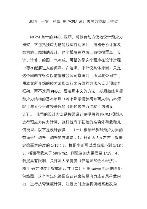
原创干货科普用PKPM设计预应力混凝土框架PKPM自带的PREC程序,可以自动方便地设计预应力框架,它包括预应力筋的线型自动设计,结构分析计算及结构施工图辅助设计。
这个模块在界面上做得很漂亮,设计、计算、绘图一气呵成,可惜的是这个程序在设计过程中存在配筋过大的问题。
在这里,不评说具体原因。
只是这个问题在很久以前就被我公司意识到,所以我公司宁可用本文所介绍的较为笨拙却行之有效的方法来设计预应力框架,而不选用PREC。
要运用本文的方法,必须熟练掌握预应力结构的基本原理(若不熟悉请参阅东南大学吕志涛院士与孟少平教授著作的《现代预应力混凝土结构设计》)。
我司的设计方法是按照设计院提供的PKPM模型来进行预应力内力计算,这样就有了初始的准确外荷载和几何模型。
以下是设计步骤:(一)根据经验对预应力梁的截面进行调整,调整的方法是:1、柱距为8m左右,就确定梁高为跨度的1/16;2、柱距小则可以适当减小到1/18;3、楼面荷载大于5KN/m2,则适当加大梁高至1/15;4、若层高有限制,只好加大梁宽度(但是显然会不经济)。
图1 确定预应力梁截面尺寸(二)利用satwe给出的弯矩包络图,这个弯矩包络图应该包含抗震内力或者风荷载内力,进行抗弯强度计算,注意此时应该将调幅系数改为1.0,因为预应力计算时不考虑塑性作用(实际上预应力次弯矩是一种弹性调幅)。
根据PPR=0.75,考虑次弯矩的影响,对跨中截面的弯矩乘以1.1系数进行初始估算,支座则乘以0.9。
由此可以得出所需的预应力筋面积Ap(单位mm2)。
Ap除以140(mm2)得到预应力筋根数。
图2 调幅系数修改图3 外荷载作用下的弯矩包络图(三)计算预应力综合弯矩,这个步骤稍微有点复杂:1、拷贝整个计算目录,在新目录中打开PKPM文件;2、将混凝土自重设置为0;3、将所有的线荷载面荷载全部删除;4、在satwe设置中不计算抗震以及风荷载。
这样先运行一遍satwe,确定恒载计算的所有内力均为0,将此状态作为初始条件。
PKPM模块PREC的预应力混凝土设计要点1、参考规范1)《混凝土结构设计规范》GB 50010-20102)《预应力混凝土结构抗震设计规程》JGJ 140-20043)《无粘结预应力混凝土结构技术规程》JGJ 92-2004 2、规范构造要求1)《预应力混凝土结构抗震设计规程》JGJ 140-2004截面尺寸:4.2.1 预应力混凝土框架粱的截面尺寸.宜符合下列各项要求:1 截面的宽度不宜小于250mm;2 截面高度与宽度的比值不宜大于4;3 梁高宜在计算跨度的(1/12~1/22)范围内选取.净跨与截面高度之比不宜小于4。
预应力强度比:3、预应力混凝土结构设计软件PREC的操作步骤:1)使用适用于三维结构体系计算的PREC1模块2、3、《混凝土结构设计规范》4、自动布置预应力筋5、存盘退出6、7、8、9、计算后调整预应力线型10、调整预应力钢筋线形的技巧初始设计时,我对预应力混凝土梁仅指定了型号为1的四段抛物线型,计算后程序提示线形不合理,根据上述技巧,我对预应力混凝土梁同时指定了型号为1的四段抛物线型+型号为3的两段折线型,如下:重新计算后,程序不再有警告信息了,说明线形合理了。
发现预应力梁跨中底部裂缝宽度为,大于裂缝限值,需加大梁底纵向钢筋。
将预应力梁底纵筋连通(按最大配)再次验算裂缝,发现变小了,但仍然超过限值;继续修改钢筋,如下:一味地增加梁底普通纵筋,对裂缝宽度控制效果不好,建议此时调整预应力线形形式或增加预应力钢筋。
我增加了预应力钢筋,由原来的每种型号13根增加为每种型号25根,发现裂预应力度均满足规范,梁底受压没有产生裂缝,说明预张拉过头。
我调整预应力线形形式,将其中的2号直线形式集中荷载作用点位置移动值预应力梁的中间(原先在1/3处),发现梁底裂缝满足要求;不过查看梁底纵筋,发现变为22d25,配筋率为%。
此时,发现本工程框架抗震等级为3级,规范规定的预应力度限值为,预应力梁左端上部为,需降低。