TM024HDH26-V02规格书(深圳市尚视界科技有限公司)
- 格式:pdf
- 大小:1.55 MB
- 文档页数:43
PRODUCTION VISESVisesIntroduction to Design ...........................................66–67VMC/HMC Solutions ............................................68–69Ball Lock® Mounting System ...............................70–71Production Vises4" (100 mm) Production Vises ................................72–736" (150 mm) Production Vises .................................74–75Self Centering Vises .................................................764" (100 mm) ................................................................76–776" (150 mm) ................................................................78–79Accessories ......................................................................79Production Vise Columns 4" (100 mm) Production Vise4 Sided ...........................................................................803 Sided ...........................................................................816" (150 mm) Production Vise4 Sided ...........................................................................823 Sided ...........................................................................8312 Station Hex .................................................................8412 & 16 Station Multi Quads ..................................85–86Hydraulic Production Vises .....................................874" (100 mm) ...............................................................88–896" (150 mm) ...............................................................89–90Hydraulic Vise Columns ...........................................914" (100 mm) 4 sided ........................................................924" (100 mm) 3 sided ........................................................936" (150 mm) 4 sided ........................................................946" (150 mm) 3 sided ........................................................95Column Subplates ..........................................................96Hydraulic Vise Accessories......................................97–98Vise Accessories ...............................................99–104Jaw Selections ..................................................99–101Ball Lock® Shanks/Plates .....................................102–103Sine Fixture Keys/T-Slot Nuts .....................................104Cast Iron Shop Vises ......................................105–106Bock Quick Change FixturingIntroduction ..................................................................107System Overview .................................................108–109Twin Vises ........................................................................110Jaw System .....................................................................111 Twin Vise Data ................................................................112Locator Plates .................................................................113DexLoc™ Locator Pins ...................................................113 Mono-Quad System (114)5-Axis Production VisesIntroduction ...................................................................115Self Centering .................................................................116Jaws /Accessories ................................................117–118Fixed .................................................................................119Jaws/Accessories .......................................................120Quick Clamping Block .................................................121Super Compact Clamp .................................................122Jaws/Accessories ...............................................123–124Vise with Reversible and Interchangeable Inserts ...125Jaws/Accessories .......................................................125Pallet Clamps .. (126)P R O D U C T I O N V I S E SWORKHOLDING SOLUTIONS GROUPPRODUCTION VISESJergens Production Vise SystemFastest Quick Change Jaw SystemMaximum Holding Power• Jaws machined to the contour of your workpiece maximizing holding force.6" (150mm) MonoQuad4" (100mm) MonoQuad• Quick change reverseable soft jaws • Single station adapter plate included• Multiple base designs to meet any requirementDual Station VisesSelf-Centering VisesWORKHOLDING SOLUTIONS GROUPPRODUCTION VISESJergens Production VisesMachine “Pockets” into the vise jaws, in the shape of your workpiece.Benefit: Reduce set-up times and parts change overMultiple mounting base configurations Fully sealed lead screw assemblyBenefit: Lower maintenance Rigid construction with hardened and ground stainless steel railsBenefit: High accuracy and repeatabilityChip and fluid flow through baseBenefit: Easier to keep clean, no more cloggingWORKHOLDING SOLUTIONS GROUPPRODUCTION VISESVertical Machine SolutionsHydraulic Vise Pages 88–90Innovative compact design. Reduced set-up time.Internal Slide Assembly with Hydraulic Clamping Cylinder.Universal Base Production Vises Pages 73 & 75The mounting flange has slotted holes to allow Ball Lock ® Base Production Vises Pages 72 & 74The mounting flange is cut into a jigsaw pattern to allowvises to nest closely together. Designed for use with Jergens Ball Lock ®Mounting System.5-Axis production vises and accessories rigidly clamp parts without obstructing access to multiple part faces.Self Centering Vises (3 Base Styles)Pages 76–79Self-Centering vises provide quick, simple fixturing for concentric machining of different sized workpieces.Narrow Base Production Vises Pages 73 & 75The small footprint allows maximum density of vises on your Bock Brand Quick Change System Pages 107–114Bock Brand vises combine with alpha-numeric locator plates Indexer Systems Page 81Indexer solutions can be customized to yourrequirements. Choose either three or four sided columns.WORKHOLDING SOLUTIONS GROUPPRODUCTION VISES Horizontal Machine Solutions6-Sided Production Vise ColumnsPage 84Increase the number of parts per load, while maintaining a small footprint. Available with bases to fit directly onto 4-Sided Production Vise Multi-Columns Pages 85 & 86Multiple columns mounted on a single base provide 12 or 163-Sided Production Vise ColumnsPages 81 & 83For machining 3 faces of production parts on HMC's. Largespindle noses can access the workpiece.240° workpiece accessibility.Multi-Vise FixturesPages 73, 75, 77, 79 & 89T o maximize productivity, mount multiple narrow body visesonto a single fixture plate. Mount the fixture plate onto thetombstones with the Jergens Ball LockWORKHOLDING SOLUTIONS GROUP PRODUCTION VISESSystem accurately positionsThe Ball Lock System securely holds fixtureplates to subplates with up to 20,000 lbs (88kN)of hold-down force per shank.Ball Lock® Fixture Mounting System forThe Ball Lock® Mounting System provides a method of quickly and accurately locating fixtures onto machine tables. The Ball Lock Commonly Asked QuestionsQ. What is the Ball Lock®Mounting System?It is a means of locating and lockingtwo flat surfaces together, normally afixture plate to a sub-plate.Q. How does it lock?A. Inside the shank are three balls thatexpand into a tapered groove in thereceiver bushing. This action drawsthe plates together. The locking ballsare activated by turning a setscrew inthe head of the shank, which pushesWORKHOLDING SOLUTIONS GROUPPRODUCTION VISESUnmatched Setup Speedand Workholding FlexibilityQ. Is there a preferable location for System repeatability is improvedif the liners are located at opposite corners of a rectangular fixture plate. For consistency, we recommend locating the liner bushings at top left Q. What are the advantages of using with ¾" (18mm) of thread engagementrequires 10 turns to lock. On CNCmachines, the repeatability of fixturelocations makes indicating of thefixture unnecessary.Q. How do I recess the fixtureplatefor a clear surface ?A. Counterbore the fixture plate to adiameter large enough to allow easyQ. What if my plate is thinner thanthe recommended thickness?A. By adjusting the depth of thecounterbore for the receiver bushingin the subplate, you can still use theBall Lockquestions on this type of application,please call 1-877-426-2504.Q. Can I use the shanks in a heated0.38[10]0.96[24]3.438[87.5]1.683.00[73]1.22[30][190]7.50WORKHOLDING SOLUTIONS GROUPPRODUCTION VISESProduction Vises – 4" (100mm)Ball Lock ShankShankPart No.Wt.Part No.SizeMetric17/32" (4) Plcs [13.5]Slotted Mounting Holes:3.13[80]2.50[63.5]6.00[150]Mounting Holes (2) Plcs:17/32"[13.5]WORKHOLDING SOLUTIONS GROUPPRODUCTION VISESProduction Vises – 4" (100mm)traditional strap clamps. The narrow base has 2 locating holes for 12mm -slots shown on page 104. Recessed machine tables, tombstones, or columns. Maximize flexibility by utilizing0.50[12]4.50[114]4.00[100]10.00[248] 1.45[38]0.96[24]WORKHOLDING SOLUTIONS GROUPPRODUCTION VISESProduction Vises – 6" (150mm)MetricBall Lock ShankShank Part No.Wt.Part No.Size1.125[28]2.952[75]4.921[125]7.874[200]6.000[150]Mounting Holes:M10 x 1.5 T ap (6) Plcs2.50[63.5]3.875[100]7.874[200]Locating Holes:.6255 (4) PlcsFor Sine Fixture KeysWORKHOLDING SOLUTIONS GROUPProduction Vises – 6" (150mm)is easily mounted directly to machine tool tables. Slotted mounting holes will match almost any table slot pattern. can be mounted as a stand-alone vise or mounted to a fixture plate. The slim design allows a high density of vises on machine tables, tombstones, or columns. Maximize flexibility by utilizing the Jergens1.22"(31.0)ED MTG. HOLES3.370"(85.60)±0.001"(0.03)WORKHOLDING SOLUTIONS GROUPSelf-Centering Precision Production Vises• Shown in Universal Base, also available in Narrow Bases and Ball Lock Part Number Wt. (lbs)49471SC38WORKHOLDING SOLUTIONS GROUPSelf-Centering Vises – 4" (100mm)12"6"WORKHOLDING SOLUTIONS GROUP Self-Centering Vises – 6" (150mm)12"6"50m m 12" (300mm )WORKHOLDING SOLUTIONS GROUPSelf-Centering Vises – 6" (150mm)Part No.49442SC*Jergens Standard Jaws fully compatible, see complete selection on page o order Jergens Production Vise Jaws with Adjustable Gib Screw, use standard jaw part no. followed by "SC".WORKHOLDING SOLUTIONS GROUP Production Vise Columns – 4" (100mm)QWORKHOLDING SOLUTIONS GROUPcan be mounted onto most any indexer. Columns can be attached directly to an indexer or become Jergens Technical Service for help designing Production Vise Columns – 4" (100mm)Mounting Wt. Ball Lock Shank Pattern 2* (lbs) Part No. Sizen/a 125 49602 20mm x 1"100mm 115 — —Mounting Wt. Ball Lock Shank Tri-column design allows upWORKHOLDING SOLUTIONS GROUP Production Vise Columns – 6" (150mm)QWORKHOLDING SOLUTIONS GROUPProduction Vise Columns – 6" (150mm)Mounting Wt. Ball Lock Shank Pattern 2* (lbs) Part No. Size252 49602 20mm x 1"266 49612 25mm x 1"100mm 240——Tri-column design allows upJBall Lock Mtg. PatternBall Lock Mtg. PatternWORKHOLDING SOLUTIONS GROUPProduction Vise ColumnsQK Ball Lock Mtg. PatternQKBall Lock Mtg. PatternWORKHOLDING SOLUTIONS GROUPPRODUCTION VISESProduction Vise ColumnsMtg. PatternK QQKBall Lock Mtg. PatternWORKHOLDING SOLUTIONS GROUPPRODUCTION VISESProduction Vise ColumnsWORKHOLDING SOLUTIONS GROUPPRODUCTION VISESHydraulic Production Vises• Innovative compact design • Internal hydraulics• 4,700 lbs (2,100 Kg) clamping force • Operates on lower input pressure • Fully machinable jaws• Fastest quick-change jaw system • Hardened stainless steel wear rails •Easy-Flow ™base designJergens hydraulic vises are available in 3 different base configurations. They offer the same unique features as Jergens manual vises.Technical Specifications:Hydraulic Clamping Stroke: 1/4" (6.3mm)Operating Volume: 0.4 Cu In (6.7 cm 3)Maximum Input Pressure: 4000 P .S.I. (275 bar)Minimum Input Pressure: 500 P .S.I. (35 bar)Input Port: #4 SAE (7/16-20 UNF-2B)Clamping Force (lbs) = Input Pressure x 1.19Clamping Force (Kg) = Input Pressure Bars x 7.67Operation:Using the Jergens Hydraulic Vise handle part number 49445, tighten vise jaws so the workpieces touch the fixed jaw. Next, turn the handle back 1/2 turn and activate the hydraulic cylinder. Hydraulic Power Sources AvailableClamping ForceInput PressureClamping ForcePSIBarslbskgf500 35 595 268 1,000 70 1,190 5376.0012.002.50[63.5]3.125[80] 6.00[150]17/32" (4) Plcs [13.5]Slotted Mounting Holes:Mounting Holes :17/32" (2) Plcs [13.5]WORKHOLDING SOLUTIONS GROUPPRODUCTION VISESHydraulic Production Vises – 4" (100mm)Mounting Holes:ap (6) PlcsMOUNTING HOLES (6) Plcs:3.938[100]LOCATING HOLES:.6255 (6) PlcsWORKHOLDING SOLUTIONS GROUPPRODUCTION VISESHydraulic Production Vises – 4" (100mm)Part Wt. N umber lbs/Kg49487 30/14Part Wt. N umber lbs/KgPart Wt.PRODUCTION VISESWORKHOLDING SOLUTIONS GROUP Hydraulic Production Vises – 6" (150mm)12.006.00PRODUCTION VISES WORKHOLDING SOLUTIONS GROUPHydraulic Vise Column(150mm) sizes,Fully Machinable and ReversibleMore workholding flexibility per jaw set.Hydraulic Vise Column Kits Include:Shown with base forSee page 98 for Air PoweredHydraulic PumpPRODUCTION VISESWORKHOLDING SOLUTIONS GROUP Hydraulic Vise Tooling Columns – 4" (100mm)PRODUCTION VISES WORKHOLDING SOLUTIONS GROUPHydraulic Vise Tooling ColumnsPRODUCTION VISESWORKHOLDING SOLUTIONS GROUP Hydraulic Vise Tooling Columns – 6" (150mm)Hydraulic Vise Tooling ColumnsHydraulic Vise Tooling Columns Standard Subplates35°TANK PRESSURE PORT1/4 NPT PORTS3.411.0260.091.0662.750.650.9380.375 AREA FOR TANK LINE LOCATION0.60 AREA FOR PRESSURE LINE LOCATION2.752 3/8"M5 X 0.8 TAP THRU (4) PLACES7/32 DRILL THRU (4) PLACESPTPORTPatent No. 3839866Hydraulic Production Vise AccessoriesPart Number61725HandlePart Number49445Handle for Hydraulic Vises, 4" Rotary Hydraulic UnionDual Passage, Ports 1/4 NPTPressure (psi) Bars Torque (in. lbs) Part Number61755 Performance Curve*(0.655)1000 2000 3000 4000 5000 (69) (138) (207) (276) (345)OUTPUT PRESSURE, PSI (BAR)Part Number61759Hydraulic Production Vise AccessoriesKit Includes61755 36:1 Pump61643 Remote four-way zero-leakageLow Pressure Air HoseHose I.D.1/4" 3/8" 1/2"HosePart Number 61106 61108 61110FittingPart Number 61107 61109 61111Hydraulic HoseHigh pressure hose is supplied assembled and to lengths indicated. Lengths are measured from end of coupling to end of coupling. Hose is 3/8" ID and available in 4000 psi or 7000 psi rating. 3/8" female tubing fittings on each end.N ipple1/8 NPT Male 619501/4 NPT Male 61905 619511/4 NPT Female61954 Air couplers have checks on sleeves only.Adapter for BSP1/4 Male NPT 1/4 NPT x 1/4 T 1/4 Female BSP 60221Adapters & ElbowsJergens Production Vise SystemThe clamping system Completely sealed lead screw Hard coated base made of high-strength, light-weight, aluminum extrusion. Guideway Rails made of hardened stainless steel.Aluminum jaws can be completely milled, therefore Aluminum or steel jaws suitable for milling:Extra Wide Jaws Full Face Vise PlateDual Station with Hard JawSingle Workpiece with Hard JawsProduction Vise JawsQuick Change Fixture PlateProduction Vise Accessoriesinclude two moveable jaws and one fixed jaw.Vise Conversion PlatesVise HandlesHard Jaw Carriers With Steel Inserts*Part No.Vise Size49442 4"/100mm Machinable Soft Jaws(Standard Sets included with Vises)Vise Work StopClearance holes for holddown (2) PlcsClearance holefor holddownStandard ShankJigsaw Fixture PlateMultiple Vise Fixture PlateProduction Vise Ball Lock ®Accessories – InchShank49601 49601-S 49602 49602-S 49611 49611-S49612 49612-SProduction Vise Ball Lock® Accessories – MetricJigsaw Fixture PlateClearance holefor holddownStandardShank Multiple Vise Fixture PlateClearance holes forholddown (2) PlcsProduction Vise Accessories Locate subplates or fixture plates to Tmachine tables. Available in inch sizes for 1/2"to 7/8" slots, and in metric sizes for 12mm to22mm slots.T-Slot NutsWORKHOLDING SOLUTIONS GROUPCast Iron Shop VisesCharacteristicsMade of close grained high tensile cast iron. Jaws ground and Hardened 55±3 HRC. Swivel base provided with positive locking and adjustable through 360°. Adjusts work piece to its center. Opposite threads for quick and accurate centering.CharacteristicsMade of close grained hightensile cast iron. Jaws ground and Hardened 55±3 HRC. Adjusts workpiece to its center. Opposite threads for quick and accurate centering. This is a low profile vise.T echnical DataPart Jaw Width Jaw Opening N umber Inch mm Inch mm Inch mm Inch mm Inch mm Inch mm 110080 2 50 2 50 110081 4 100 4 100 T echnical DataPartJaw Width Jaw OpeningNumber Inch mm Inch mm Inch mm Inch mm Inch mm Inch mm 110085 3 75 5 127 110086 4 100 4 100WORKHOLDING SOLUTIONS GROUPCharacteristicsManufactured from close grained high tensile cast iron. Swivel is full 360°. This is very useful for heavy duty milling jobs. Vise is low height for maximum clearances. Jaws are fully ground and precision with parallelism of 0.0012 (30 microns) the hardness of jaws is 55±33 HRC.T echnical DataPart Jaw Width Jaw Opening Jaw Depth N umber Inch mm Inch mm Inch mm Inch mm Inch mm Inch mm T echnical DataPartJaw Width Jaw Opening Jaw DepthNumber Inch mm Inch mm Inch mm Inch mm Inch mm Inch mm 110250 6 150 7 1/2 188 1 1/2 CharacteristicsManufactured from graded cast iron and precisionground. These vises have a needle bearing thrust collar. Vise jaws are in pairs and replaceable.Cast Iron Shop VisesMilling Machine Vises with Swivel Base (Heavy Duty)Machine VisesWORKHOLDING SOLUTIONS GROUP JERGENS-BOCK QUICK CHANGE S YS TEMFASTPRODUCTIVE by reducing spindle down-time to aminimum. The combination of short setup times, theability to move setups away from the machine andfast loading keeps your spindle cutting, not waiting.WORKHOLDING SOLUTIONS GROUPJERGENS -BOCK QUICK CHANGE S YS TEMwin Vise is the key component of the complete BockWorkholding system. A variety of body styles made from high-strength aluminum, ground steel guides, snap-on quick-change machinable aluminum jaws and a solid clamping screw and third hand mechanism System OverviewBock Locator Plate SystemBock Locator Plates are a great platform to quickly and accurately mount your T win Vises in a number of different positions. Locator/mounting holes with alpha-numeric identifiers and Bock’s DexLoc™ double-expanding locators give you +/- .0005" repeatability.DexLoc ™Locator PinsPatented DexLoc™ double-expanding locator pins allow for fast and accurate location of twin vises on locator plates.WORKHOLDING SOLUTIONS GROUP JERGENS-BOCK QUICK CHANGE S YS TEMHard-coated high-strength aluminum base for lighter WORKHOLDING SOLUTIONS GROUPJERGENS-BOCK QUICK CHANGE S YS TEMStraight basefor use on Bock Locator Plates or with toe clamps Slim-LineStandard interlockingGenerous cut-outs to prevent chip and coolant accumulationBock Twin Vise SystemThree different basestyles for your specificmounting needsWORKHOLDING SOLUTIONS GROUP JERGENS-BOCK QUICK CHANGE S YS TEM Bock Jaw SystemBock Machinable Jaws are made from high-strength aircraft grade anodized aluminum.Once machined to hold a specific part they become quick-change dedicated fixtures ideal for holding even complex shapes.STANDARD JAWS snap on and off in QUICK CHANGEFACE PLATEScan be convertedTALL JAWSto hold larger parts.123WORKHOLDING SOLUTIONS GROUP JERGENS-BOCK QUICK CHANGE S YS TEMBock Twin VisesScrew-on guideways made from hardened steelThird-hand function for fast sequential loading of partsExact positioning of center jaw using locator pins; removing center jaws allows the holding of one single large partAluminum jaws can be milled out to meet each part’s holding and locating requirements.Generous cut-outs to prevent chip and coolant accumulationStandard InterlockingStraight BaseSlim-LineWORKHOLDING SOLUTIONS GROUP JERGENS-BOCK QUICK CHANGE S YS TEM Bock Brand Locator Plate SystemBock Brand Locator PlatesDexLoc™ Locator PinsTo order DexLocWORKHOLDING SOLUTIONS GROUP JERGENS-BOCK QUICK CHANGE S YS TEMBock Mono-Quad System。

IAD104HV300R002Product OverviewIssue V3.0Date 2017-04-26Copyright © Huawei Technologies Co., Ltd. 2017. All rights reserved.No part of this document may be reproduced or transmitted in any form or by any means without prior written consent of Huawei Technologies Co., Ltd.Trademarks and Permissionsand other Huawei trademarks are trademarks of Huawei Technologies Co., Ltd.All other trademarks and trade names mentioned in this document are the property of their respective holders.NoticeThe purchased products, services and features are stipulated by the contract made between Huawei and the customer. All or part of the products, services and features described in this document may not be within the purchase scope or the usage scope. Unless otherwise specified in the contract, all statements, information, and recommendations in this document are provided "AS IS" without warranties, guarantees or representations of any kind, either express or implied.The information in this document is subject to change without notice. Every effort has been made in the preparation of this document to ensure accuracy of the contents, but all statements, information, and recommendations in this document do not constitute a warranty of any kind, express or implied.Huawei Technologies Co., Ltd.Address:Huawei Industrial Base Bantian, Longgang Shenzhen 518129 People's Republic of ChinaWebsite:Product Overview ContentsContents1 Product orientation and features (1)1.1 Product orientation (1)1.2 Product Features (2)2 Product structure (4)2.1 Overview (4)2.2 Hardware structure (4)2.2.1 Front panel (4)2.2.2 Rear panel (5)2.2.3 Software structure (6)3 Product and Networking Application (7)3.1 Overview (7)3.2 Networking Applications (8)3.2.1 Multiple Upstream Modes (9)3.2.2 Shop access (10)3.2.3 Home Access (11)4 Technical Specifications (12)4.1 Technical Specifications (12)4.2 Compliant Standards (13)A Glossary (15)1 Product orientation and features1.1 Product orientationThis product description is about IAD104H V300R001 version.The IAD (Integrated Access Device) 104H (the IAD104H for short) is an importantcomponent of Huawei next generation network (NGN/IMS) solution. It provides small-capacity voice over IP (V oIP) or fax over IP (FoIP) solutions for enterprises and consumerusers.With different access capabilities (IAD104H: four ports) for enterprises, the IAD104H is wellintegrated into enterprise broadband networks and achieves cost-efficient access for remoteenterprise users because of its comprehensive advantages (high quality, high benefits, and costefficiency). Its flexible networking and QoS policies ensure high quality of delay-sensitivevoice services and packet-loss-sensitive fax services for end users.Figure1-1 illustrates thenetworking of the IAD104H.Figure 1-1the location of IAD104H in the network1.2 Product FeaturesThe IAD104H features: high-quality voice, easy installation, convenient management andmaintenance, high reliability and security.High-Quality VoiceThe IAD104H provides high-efficiency and high-quality IP-based voice service, by thefollowing:●Voice Activity Detection (V AD)●Comfort Noise Generation (CNG)●Echo cancellation●Lost-packet compensationEasy InstallationThe IAD104H has a simple box structure and is installed on the desktop or in the corridor.It provides standard external ports and clear marks to facilitate the installation and cableconnection.It uses standard connectors and no special installation tools are needed.It supports auto-configuration through DHCP, which frees end users from manualconfiguration on IAD.ManageabilityThe 104H can be managed in many ways.●Local console manageIAD104H can be managed by local console port, that means computer connect with IADconsole port, using Windows 98, Windows NT, Windows 2000 or Windows XP superterminal software having by the operating system to manage.●TelnetYou can telnet to the system by network ports of the IAD104H for management. Easy MaintenanceThe IAD104H supports the following maintenance methods:●Through network ports for maintenance, you can rapidly and easily set the IAD104H anddetect its status.●Besides the Basic Input/ Output System (BIOS) mode, you can load host softwarethrough network ports by File Transfer Protocol (FTP).●The IAD104H enables device maintenance, fault detection and network managementalarms.High ReliabilityThe IAD104H ensures device reliability by the following:●Watch dog timer(WDT) helps automatic recovery in case of software abnormality.●Power supply and ports can be protected from over-current and over-voltage.High SecurityThe IAD104H realizes high security by the following:●UCEMS implements management on the IAD104H, and the SoftSwitch/IMS completesthe control functions. Before provisioning services, the IAD104H needs to register in theSoftSwitch/IMS for management and service authentication.●When an IAD104H device is put into service, the device ID, secret key, IP address ordomain name of the UCEMS, and IP address or domain name of the SoftSwitch, will beassigned onto the IAD104H. The information will not get lost even if the IAD104H ispowered off.●The IAD104H management system authorizes and authenticates users to preventunauthorized users from login to and operating the device. Users can be divided intocommon users, operators and managers. Authorities are subject to the user level. Even ifusers of different levels enter the same mode, they cannot run the same commands.●The IAD104H offers various logs, such as operation, alarm and debugging logs, torecord device operation and maintenance. Operation logs record user name, login time,login mode, IP address and operations. Alarm logs record major events during systemrunning. Most of such events are alarms. Debugging logs collect debugging information.2 Product structure2.1 OverviewIAD104H designed in box structure, the whole system is constitute of main control board,power board and box. This system doesn’t support online expand, the products we provide touser are fixed configuration.2.2 Hardware structureFigure 2-1the appearance of the IAD104H2.2.1 Front panelThe IAD104H provides indicators on its front panel. Table 1-1 lists names and meanings ofthe indicators.Table 2-1the indicators of IAD104H2.2.2 Rear panelFigure 2-2hows external ports on the IAD104H rear panel.Figure 2-2External ports of the IAD104HT able 2-2 lists functions and amount of the external ports.Table 2-2External ports of the IAD104H2.2.3 Software structureThe software structure of IAD104H is based on Vxworks, it is made of CSP board, CPU andDSP, as showing in Table 2-3.Table 2-3The software structure of IAD104HFrom the software structure, IAD104H can be separated in: management and maintenancemodule, service interface module, semi-permanent service processing module, V oIP serviceprocessing module, protocol processing module, operating system module (VxW orks) andbottom drive processing module. Figure 1-4 shows the relationship of every module.T able 1-5 shows the function of each module of IAD104H.Table 2-4Instruction of each module of IAD104HProduct Overview 3 Product and Networking Application3 Product and Networking Application3.1 OverviewIt provides V oIP access for up to four POTS users, and offers one LAN port and one WANport.Services and FunctionsThe IAD104H provides abundant voice and data services, functions as listed below:●Supporting POTS and enabling Ethernet users to access the IP network●Supporting 802.1p/q●Supporting T.38 fax or transparent transmission of faxes●Supporting Caller Identification Display●Supporting Advice of Charge at the End of Conversation (the IAD of MGCP only)●Enabling calling parties of the card service to redial numbers●Supporting Point-to-Point Protocol over Ethernet (PPPoE)●Supporting Network Address Translation(NA T)●Supporting traditional PSTN services●Supporting G.711 and G.729●Supporting KC charging and polarity reversal charging controlled by the SoftSwitch(IAD of MGCP only)●Supporting Differentiated Services Code point (DSCP)●Supporting Comfort Noise Generation (CNG)●Supporting V AD (Voice Activity Detection)●Cooperating with the SoftSwitch to provide new intellectual and distinctive services,such as Call Transfer Call Waiting , Calling Line Identification Presentation, Designatedpickup , Co-group pickup , Three-party call and Conference call (Note: the aboveservices can be used only after you subscribe them from the operator. For details, contactthe operator)●Supporting Simple Network Management Protocol (SNMP)●Supporting Simple Network Time Protocol (SNTP)●Supporting Dynamic Host Configuration Protocol (DHCP) and DHCP Relay●Supporting usage under execrable environments●Supporting end-to-end signaling tracing, and locating software/hardware faults insidedevices●Supporting IAD authentication by SoftSwitch●Supporting encryption of RFC2833 controlled by SoftSwitch (the IAD of SIP only)●Supporting certifications such as Federal Communications Commission (FCC), Councilof Europe (CE) and China Compulsion Certification (CCC)●Supporting auto-configuration through DHCP, which frees end users from manualconfiguration on IAD.3.2 Networking ApplicationsIAD104H can be applied in the below scene.3.2.1 Multiple Upstream ModesFigure 3-1Upstream modes of IAD104HTable 3-1Noun explain3.2.2 Shop accessFigure 3-2Shop access of IAD104HDescription:ONU realize Ethernet connect to equipment room of enterprise, IAD provide shopintegrate service access.Feature:One-line access, simple Deployment. Each shop access by one line, while providing voice,fax and broadband Internet access, meets the requirement of business office.Flexible service specification Networking. Providing 4 different configurationspecification to satisfy diversiform data, voice and fax application request.Supporting IP-Centrex. Support internal call by short number, improve work efficiency.Supproting Number Portability. It's not necessary to apply to change number and modifyIAD configuration when the relocation. Support plug and play, and fully protect the benefit ofthe merchants, such as telephone and fax number.3.2.3 Home AccessFigure 3-3Home access of IAD104HDescription:ONU is deployed in Residential districts, using the existing LAN SW to access to home.Features:One-line access, simple Deployment. ONU provide 8/16/24 port floor exchange, Eachretail access by one line with IAD, no need line repeatly. At the same time to increase thecustomer satisfaction and reduce deploying cost.PPPoE dial-up automatically. Through IAD’s embedded PPPoE function, PC connectedwith it can access Internet network directly without any other operation, thus simply theprocess of dial-up.Flexible Service CombinationT wo solutions can be provided according to different family requirements:a)Provide standard telephone and internet service;b)Fax service is added on the basis of solution A in SOHO environment.4 Technical Specifications 4.1 Technical SpecificationsTable 4-1IAD104H Technical Specifications4.2 Compliant StandardsThe IAD104H is in compliance with the following standards and protocols.Tone detection/generation●Dual tone multi-frequency (DTMF), call tones (such as dialing tone, busy tone, ring backtone, and offhook prompt tone)●V.17, V.21, V.27ter, V.29 standards●Automatic identification of voice and fax servicesVoice/Multimedia data signal codec●ITU-T G.711 μ-Law (64kbit/s)●ITU-T G.711 A-Law (64kbit/s)●ITU-T G.729Call signal protocol for call control●Internet Engineering Task Force (IETF) MGCP (RFC3435)●SIP (RFC3261)Encapsulation and decapsulation protocols of voice packets●RTP/Real-Time Control Protocol (RTCP) (RFC 1889)●Internet protocols●Transfer Control Protocol (TCP)/IP●User Datagram Protocol (UDP)/IP●Address Resolution Protocol (ARP)/Reverse Address●Resolution Protocol (RARP)●Internet Control Message Protocol (ICMP)●Telnet●Hypertext Transfer Protocol (HTTP) Web Server●Domain Name Server (DNS) Client●DHCP Client●FTP (File Transfer Protocol)/TFTP (Trivial File Transfer Protocol) ClientIP address allocation●Static●DHCP●PPPoEIP fax●Transparent transmission●Transmission mode meets ITU-T T. 38 Real-Time IP G3 fax protocol, with the rate lessthan 14400 bit/sA Glossary Table 4-2Abbreviations。
1⁄8 DIN Digital Panel Temperature Meters For Thermocouple and RTD InputsSpecificationsDisplay: 5-digit, 14.2 mm (0.56") redLED, (-19999 to 99999)Power:AC Versions:AC Power: 85 to 250 Vac,50/60 Hz, 10 VA Isolation: 2300 Vrms for 1 minuteto all inputs Low Voltage Versions: DC Power: 11 to 36 Vdc, 11 WAC Power: 24 Vac, ± 10%,50/60 Hz, 10 VA Isolation: 500 Vrms for 1 minuteto all inputs (50V working)Keypad: 3 programmable function keys,5 keys total A/D Converter: 16-bit resolutioncapabilities to suit a wide range of industrial applications. These meters accept thermocouple or RTD inputs. The meters provide a maximum and minimum reading time. The capture time is used to prevent detection of false max or min readings which may occur events. These meters have been specifically designed for harsh industrial environments. With extensive testing of noise effects to CE requirements, the DP63400 reliable, application solution.U Thermocouple and RTD Panel MeterU 5-Digit, 14 mm (0.56") LEDU Conforms to ITS-90 StandardsU °F or °C Unit Overlay with BacklightU NEMX 4X (IP65)Update Rates: A/D Conversion Rate: 10 readings/s Step Response: 200 ms max to within 99% of final readout value (digital filter and internal zero correction disabled), 700 ms max (digital filter disabled, internal zero correction enabled) Display Update Rate: 1 to 10 updates/s Max/Min Capture Delay Time: 0 to 3275 s Low-Frequency Noise Rejection: Normal Mode: >60 dB @ 50 or 60 Hz ±1%, digital filter off Common Mode: >100 dB, DC to 120 Hz Memory: Non-volatile E 2PROM retains all programmable parameters and display values Environmental Conditions: Operating Temperature Range: 0 to 50°C (32 to 122°F) Storage Temperature Range: -40 to 60°C (-40 to 140°F) Operating and Storage Humidity: 0 to 85% max RH non-condensing Altitude: Up to 2000 m (6562')Connections: High-compression, cage-clamp terminal block Wire Strip Length: 7.5 mm (0.3")Wire Gage: 30 to 14 AWG copper wire Torque: 0.51 N/m (4.5 lb/in) max Construction: This unit is rated for NEMA 4X (IP65) outdoor use, IP20 touch-safe, Installation Category II, Pollution Degree 2, 1-piece bezel/case, flame-resistant, synthetic rubber keypad—panel gasket and mounting clip includedWeight: 200 g (7 oz)DP63400-T shown smaller than actual size.**Offset Range: -19,999 to 99,999 display units Input Impedance: 20 M ΩLead Resistance Effect: 0.03µV/ΩMaximum Continuous Overvoltage: 30VType: 3- or 4-wire, 2-wire can be compensated for lead wire resistance Excitation Current: 100 Ω Range: 165 µA 10 Ω Range: 2.6 mADirect ReadoutInput Range: -10 to 65 mV 0 to 400 Ω: High range0 to 25 Ω: Low rangeDisplay Range: -19999 to 99999Ordering Example: DP63400-T-LV, temperature input, 11 to 36 Vdc.100 Ω Range: 10 Ω/lead max 10 Ω Range: 3 Ω/lead max。

VC-01-Kit规格书V1.0.0VC- -Kit规格书版本V . .版权 ©文件履历表目录1.产品概述 (4)1.1.特性 (5)2.主要参数 (6)2.1.静电要求 (6)2.2.电气特性 (7)2.3.功耗 (7)3.外观尺寸 (8)4.指示灯及按键说明 (9).管脚定义 (10).原理图 (12).产品相关型号 (13)8.固件烧录方式说明 (13)9.产品包装信息 (14)10.联系我们 (14)免责申明和版权公告 (15)注意 (15)1.产品概述VC-01-Kit是针对VC-01模组设计的开发板,该底板与VC-02-Kit共用。
开发板上集成了CH340C串口转USB芯片,提供基础的调试接口及USB升级接口;唤醒灯及冷暖灯的设计,提供了状态指示及控制指示,且方便调试简单的控制功能。
VC-01是深圳市安信可科技有限公司开发的一款低成本纯离线语音识别模组。
该模组使用云知声推出的语音芯片US516P6,在语音识别技术上不断优化和创新算法,离线识别算法与芯片架构深度融合,为客户提供超低成本的离线语音识别方案,可广泛且快速应用于智能家居,各类智能小家电,86盒,玩具,灯具等需要语音操控的产品。
US516P6芯片采用32bit RSIC架构内核,并加入了专门针对信号处理和语音识别所需要的DSP指令集,支持浮点运算的FPU运算单元,以及FFT加速器。
VC-01支持150条本地指令离线识别,支持RTOS轻量级系统,具有丰富的外围接口,以及简单友好的客制化工具。
图1US516P6芯片架构图1.1.特性内核32bit RISC内核,运行频率240MHz支持DSP指令集以及FPU浮点运算单元FFT加速器:最大支持1024点复数FFT/IFFT运算,或者是2048点的实数FFT/IFFT 运算云知声定制化语音算法算子存储内置242KB高速SRAM内置2MB FLASH音频输入输出灵活配置支持 . / . / . V IO支持1路模拟Mic输入,SNR≥94db支持双声道DAC输出支持中英文语音指令供电和时钟支持5V电源输入内置5V转3.3V,3.3V转1.2V LDO为芯片供电RC 12MHz时钟源和PLL锁相环时钟源内置POR(Power on Reset),低电压检测和看门狗外设所有GPIO均可配置为外部中断输入和唤醒源1个全双工UART最高速率3Mbps。
TRINAMIC Motion Control GmbH & Co. KGHamburg, GermanyHardware Version V 1.10HARDWARE MANUAL+ +TMCM-12101-Axis steppercontroller/drivermax. 0.6A RMS / 24V DC STOP / HOME switch input hall sensorRS485++Table of contents1Life support policy (3)2Features (4)3Order codes (5)4Mechanical and Electrical Interfacing (6)4.1Dimensions and Mounting Holes (6)4.2Board mounting considerations (6)4.3Connectors (7)4.3.1Power, RS485 + HOME connector (8)4.3.2Motor connector (9)4.4Power supply (9)4.5RS485 (10)5Motor driver current (12)6On-Board LEDs (13)7Reset to Factory Default Values (13)8EMC considerations (14)9Operational Ratings (15)10Functional Description (16)11Revision History (17)11.1Document revision (17)11.2Hardware revision (17)12References (17)1Life support policyTRINAMIC Motion Control GmbH & Co. KG does not authorize or warrant any of its products for use in life support systems, without the specific written consent of TRINAMIC Motion Control GmbH & Co. KG.Life support systems are equipment intended to support or sustain life, and whose failure to perform, when properly used in accordance with instructions provided, can be reasonably expected to result in personal injury or death.© TRINAMIC Motion Control GmbH & Co. KG 2015 - 2019Information given in this data sheet is believed to be accurate and reliable. However neither responsibility is assumed for the consequences of its use nor for any infringement of patents or other rights of third parties, which may result from its use.Specifications are subject to change without notice.2FeaturesThe TMCM-1210 is a highly compact 20mm x 20mm single axis stepper motor controller and driver board with RS485 interface. It has been designed in order to be mounted on the rear side of a NEMA8 (20mm flange size) stepper motor and offers an integrated hall-sensor based encoder IC in addition to a reference switch input for easy homing / search of reference position. The module supports motor currents up to 0.6A RMS and supply voltages up to 24V DC nominal. It is available with standard TMCL firmware and supports stand-alone operation (TMCL programs with auto-start stored on-board) and remote control via RS485 interface.MAIN CHARACTERISTICSMotion controller∙Motion profile calculation in hardware in real-time∙Motion controller supports linear and sixPoint™ ramps∙On the fly alteration of motor parameters (e.g. position, velocity, acceleration)∙High performance microcontroller (Cortex-M0+) for overall system control and serial communication protocol handlingBipolar stepper motor driver∙Up to 256 microsteps per full step∙Highly integrated and highly-efficient operation∙Dynamic current control∙stallGuard2™ feature for stall detectionInterfaces∙RS485 2-wire communication interface∙Digital input IN0 (+24V compatible), can be used as reference switch or left and/or right stop switch input, alsoOn board hall sensor∙Absolute sensor within one motor rotation∙12bit / 4096 steps / revolution max.∙Low-cost sensor - suitable for low velocity applications (few hundred rpm) –e.g. initial reference search (together with HOME sensor input) after power-upSoftware∙TMCL™ remote (direct mode) and standalone oper ation with memory for up to 876 TMCL commands∙Fully supported by TMCL-IDE (PC based integrated development environment)Electrical data∙Supply voltage: +7V… +30V DC∙Motor current: up to 0.6A RMS (programmable)Mechanical data∙Board size: 20mm x 20mm, overall height 9mm max. (without mating connectors and cables)∙Mounting holes compatible with NEMA 8 stepper motors (for mounting the board to the rear side of a NEMA8 stepper motor using two of the four existing screw)Please see separate TMCM-1210 Firmware Manual for additional information regarding firmware functionality and TMCL programming.3Order codesThe TMCM-1210 is available as:A cable loom set is available for this module, also:Table 3.2: Cable loom order code4 Mechanical and Electrical Interfacing4.1 Dimensions and Mounting HolesThe dimensions of the board are approx. 20mm x 20mm x 9 mm in order to fit on the back side of a 20mm (NEMA8) stepper motor. Maximum component height (height above PCB level) without mating connectors is around 6mm above PCB level and 2 mm below PCB level. There are two mounting holes for M2 screws for mounting to a NEMA8 stepper motor.2xFigure 4.1 Dimensions of TMCM-1210 and position of mounting holes (with comparison of size)4.2 Board mounting considerationsThe TMCM-1210 offers two metal plated mounting holes. Both mounting holes are connected to power supply ground. Please keep this in mind when mounting the board to the rear side of a motor.Figure 4.2: Example of TMCM-1210 mounted to NEMA 8 stepper motor4.3 ConnectorsThe TMCM-1210 offers two connectors including the motor connector which is used for attaching the motor coils to the electronics. The Power, RS485 and HOME connector is used for power supply, RS485 serial wire communication and offers one digital input.4115Power, RS485 + HOME connector HOME 5RS485+RS485-34VDD GND 12IN0STOP_L / STOP_R Motor connectorOA1OA234OB1OB212Figure 4.2 Overview connectorsOverview of connectors and mating connectors types:Table 4.1: Connectors and mating connectors, contacts and applicable wire4.3.1Power, RS485 + HOME connectorThe module offers one combined power, RS485 2-wire serial communication and digital input (HOME) connector (JST PH series).51Table 4.2: Power, RS485 + IN0 connector4.3.2 Motor connectorAs motor connector a 4pin JST PH-series 2mm pitch single row connector is available. The motor connector is used for connecting the four motor wires of the two motor coils of the bipolar stepper motor to the electronics. 14Table 4.4: Motor connector 4.4 Power supplyFor proper operation care has to be taken with regard to power supply concept and design. Due to space restrictions the TMCM-1210 includes just about 20µF/35V of supply filter capacitors. These are ceramic capacitors which have been selected for high reliability and long life time.4.5RS485For remote control and communication with a host system the TMCM-1210 provides a two wire RS485 bus interface. For proper operation the following items should be taken into account when setting up an RS485 network:1.BUS STRUCTURE:The network topology should follow a bus structure as closely as possible. That is, the connection between each node and the bus itself should be as short as possible. Basically, it should be short compared to the length of the bus.termination resistor (120 Ohm)termination resistor (120 Ohm)Figure 4.6: Bus structure2.BUS TERMINATION:Especially for longer busses and/or multiple nodes connected to the bus and/or high communication speeds, the bus should be properly terminated at both ends. The TMCM-1210 does not integrate any termination resistor. Therefore, 120 Ohm termination resistors at both ends of the bus have to be added externally.3.NUMBER OF NODES:The RS485 electrical interface standard (EIA-485) allows up to 32 nodes to be connected to a single bus.The bus transceiver used on the TMCM-1210 unit (SN65HVD3085E) has a significantly reduced bus load and allow a maximum of 255 units to be connected to a single RS485 bus using TMCL firmware. Please note: usually it cannot be expected to get reliable communication with the maximum number of nodes connected to one bus and maximum supported communication speed at the same time. Instead, a compromise has to be found between bus cable length, communication speed and number of nodes. MUNICATION SPEED:The maximum RS485 communication speed supported by the TMCM-1210 hardware is 1Mbit/s. Factory default is 9600 bit/s. Please see separate TMCM-1210 TMCL firmware manual for information regarding other possible communication speeds below the upper limit in hardware.5.NO FLOATING BUS LINES:Avoid floating bus lines while neither the host/master nor one of the slaves along the bus line is transmitting data (all bus nodes switched to receive mode). Floating bus lines may lead to communication errors. In order to ensure valid signals on the bus it is recommended to use a resistor network connecting both bus lines to well defined logic levels.There are actually two options which can be recommended:Add resistor (Bias) network on one side of the bus, only (120R termination resistor still at both ends):termination resistor(120R)RS485- / RS485Btermination resistor (120R)RS485+ / RS485AFigure 4.7: Bus lines with resistor (Bias) network on one side, onlyOr add resistor (Bias) network at both ends of the bus (like Profibus™ termination):termination resistor (220R)RS485- / RS485BRS485+ / RS485A termination resistor (220R)Figure 4.8: Bus lines with resistor (Bias) network at both endsCertain RS485 interface converters available for PCs already include these additional resistors (e.g. USB-2-485 with bias network at one end of the bus).5Motor driver currentThe on-board stepper motor driver operates current controlled. The driver current may be programmed in software with 32 effective scaling steps in hardware.Explanation of different columns in table below:Motor current setting in software (TMCL)These are the values for TMCL axis parameter 6 (motor run current) and 7 (motor standby current). They are used to set the run / standby current using the following TMCL commands:SAP 6, 0, <value> // set run currentSAP 7, 0, <value> // set standby current(read-out value with GAP instead of SAP. Please see separate TMCM-1210 firmware manual for further information)Motor currentI RMS [A]Resulting motor current based on motor current setting6On-Board LEDsThe board offers one LED in order to indicate board status. The function of the LED is dependent on the firmware version. With standard TMCL firmware the green LED should be flashing slowly during operation.GREEN LEDFigure 6.1 On-board LED7Reset to Factory Default ValuesIn order to reset all settings (e.g. incl. address and RS485 baud rate) to factory default values please follow instruction sequence below:1.Switch OFF power supply.2.Short programming pads on bottom of PCB as shown in figure 7.1.3.Switch ON power supply (on-board LED should start flashing fast).4.Switch OFF power supply.5.Remove short circuit.Figure 7.1 Reset to factory default values (bottom view of pcb)8EMC considerationsThe TMCM-1210 contains ferrite beads on-board in line with the positive supply input and all 4 motor windings connections in addition to filter capacitors.Tests have shown that it is possible to meet Class B emission standards using the bare TMCM-1210 (motor and power connected) with the motor running slowly at maximum current (0.7A RMS) and +24V supply voltage without additional / external filters.Figure8.1:SetupwithTMCM-1210andattachedmotor(***************************/24Vsupply,stand-alone mode using on-board TMCL-autostart-program)Figure 8.2: measurement results (example)Please note that these measurement results using a bare TMCM-1210 unit with only motor and power supply connected do not imply any guarantee for a complete system with one or more integrated TMCM-1210 with meeting any emission limits.9Operational RatingsThe operational ratings show the intended or the characteristic ranges and should be used as design values. In no case shall the maximum values be exceeded!Table 9.1 General operational ratings of modulePERATIONAL RATINGS OF SWITCHTable 9.2 Operational ratings of HOME + STOP switches / IN0 inputsPERATIONAL RATINGS OF INTERFACETable 9.3: Operational ratings of RS485 interface10Functional DescriptionThe TMCM-1210 is a highly integrated controller/driver module which can be controlled via several serial interfaces. Communication traffic is kept low since all time critical operations (e.g. ramp calculations) are performed on board. The nominal supply voltage of the unit is 12V or 24V DC. The module is designed for both, standalone operation and direct mode. Full remote control of device with feedback is possible. The firmware of the module can be updated via the RS485 serial interfaces.In Figure 10.1 the main parts of the TMCM-1210 are shown:∙microprocessor, which runs the TMCL operating system (connected to TMCL memory),∙motion controller (part of TMC2130), which calculates ramps and speed profiles internally by hardware, ∙driver (part of TMC2130) with stallGuard2™ and its energy efficient coolStep™ feature and stealthCh o p™ for extremely quiet operation∙hall sensor based encoder which delivers position feedback at low speed (few 100rpm max.) – can be used for reference search e.g. after power-up7…Figure 10.1 Main parts of the TMCM-121011Revision History11.1D ocument revisionTable 11.1: Document revision11.2H ardware revisionTable 11.2: Hardware revision12References[JST] JST connector[TMC2130] TMC2130 datasheetManual available on [TMCL-IDE] TMCL-IDE User ManualManual available on .。
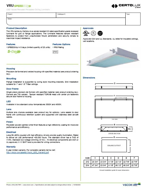
Consult installation guide for exact dimensions.CEILING CUTOUT SIZE A B C D E F 2X223 3/4”23 3/4” 4 1/8”22 1/2”22 7/8”22 7/8”2X447 3/4”23 3/4”4 1/8”46 1/2”46 3/4”22 7/8”ATOP VIEW7/8” WIRING ACCESSEDCROSS SECTIONCBFHousingPrecision die formed and welded housing with specified material (see product ordering key).MountingFlange installation is supported by swing style mounting brackets. Grid installation suitable for 1” and 1.5” T-Bar ceilings.Door FrameSingle piece precision die formed with specified material (see product ordering key). Corners are TIG welded. Tamper resistant TORX® Head with center pin fasteners secure door frame to housing.LEDAvailable in two standard colour temperatures 3500K and 4000K.LensMultiple lens choices available (see product key for options). Lens sealed to door frame with continuous retention system and supported with stainless steel aircraft cables.FinishPolyester powder painted white finish features a high reflectivity coating for improved performance and efficiency.ElectricalLong life LED’s coupled with high efficiency drivers provide quality illumination. Rated to deliver an L80 performance >50,000 hours. The standard driver has a THD of <10%. Standard low-voltage dimming (0-10v). All electrical components are CSA or UL approved. A ½” EMT hole is provided for wiring connections.Warranty5 year limited warranty. For complete warranty terms visit:/assets/Viscor_LED_Warranty.pdfDimensionsApprovalsApproved CSA and UL Standards. UL listed for insulated ceilings, wet locations.ICRATEDProduct DescriptionThe VRU series by Certolux is a vandal resistant IC-rated specification grade recessed luminaire for grid or flange applications. The luminaire features tamper resistant fasteners to protect from unauthorized fixture penetration and security lenses to maximize impact resistance.Features• SPEEDShip in 5 days (limited quantity of 25 units)Features Options• IP65 RatingOrder KeyEXAMPLE: VRUI2X2A/ALED840K055LUNV-P13/P45PhotometricCRI8 - (80-89)8A AVoltageUNV - 120-277V347 - 347VCCT35K - 3500 K40K - 4000 KSize NominalLumens Watts 2x25500532x45500477000611000082LEDVRUSeriesSize(Width xLength)2x22x4 Door StyleI - InsetO - OverlappingDoorGaugeA - 18 Ga. CRS - PaintedHousingGaugeA - 18 Ga. CRS - PaintedInternal/ExternalLensP13 - .125 Prismatic AcrylicP45 - .125 Clear Polycarbonate/-/NominalLumens055L - 5500lm070L - 7000lm100L - 10000lm2x42x2VRUI-2X2-LED840K055LUNV-P82P08IES File:VRUI-2X2-LED840K055LUNV-P82P08Lumens:5569Wattage:52Efficacy:1070°10°20°30°40°50°60°70°80°90200 cd 400 cd 600 cd 800 cd 1000 cd 1200 cd 1400 cd 1600 cd 1800 cd 2000 cd 2200 cd 2400 cdZonal Lumen SummaryZone Lumens%Lamp0.0° - 30.0°1723-43,083.6%30.9%0.0° - 40.0°2764-69,091.0%49.6%0.0° - 60.0°4646-116,155.7%83.4%0.0° - 90.0°5569-139,225.4%100.0%Average Luminance Table (cd/m2)CP Summary0.00°45.00°90.00°0.00°63646364636445.00°52025147523255.00°46644579468165.00°39103791391575.00°26592559278085.00°79711701738Coefficients of Utilizationρc80%70%50%ρw70%50%30%70%50%30%70%50%30%0119119119116116116111111111111010510110710399102999621009386989185938782392827489807385777148473658272647869625786557766456726255672595070585067564976754456553456251448624941614841584740958453757453754443610554234534134514033Effective Floor Cavity Reflectance: 20%P13P45OptionsApproval OptionsX8 IP65 RatingOther options may be available, consult factory.Specifications and data subject to change without notice.。
本说明书由天津曙光敬业科技有限公司翻译This manual has been translated by Tianjin Aurora UA V Technology Co.,Ltd.尊敬的用户,欢迎购买我们的数字开关。
此产品是世界上第一个多功能开关系统,由PowerBox Systems GmbH研发、生产。
它专门使用轻巧的锂电池,在接收机电源供应的开关安全性上有很大改善。
此产品外壳坚固并带有一个自锁电子开关、一个高性能线性IC控制稳压电路和一个电压监测器。
此电压监测器使用一个两芯锂电池和一个五芯镍镉/镍氢电池组,分四个阶段进行监测。
重要的构造特点:坚固的塑料外壳(材质为30%的玻璃纤维)、两根连接导线、一根横截面为0.34mm2的硅导线直接焊接在焊接板上(如在同一直线上),焊接板封装在专用的胶层中以防振、SMT安装电路板、编程控制的线路转换程序以及两个散热片(其中一个焊接在电路板上)。
我们建议将数字开关用于以下类型的模型:-带有五个标准尺寸舵机的中小型模型飞机-F3A模型(非常适用于此模型)-带有八个或八个以上舵机的滑翔机,依据舵机尺寸、模型尺寸和飞行类型(热飞行或特技飞行)-电力驱动或光驱动的直升机,转子直径为1.30m,最多带有五个舵机-电力驱动或光驱动的RC模型汽车-模型船-汽油机点火系统的电压为四芯镍镉电池的电压(DA或其它)操作:数字开关由一个按钮控制,操作起来非常简便。
此按钮也用来设置想要安装的电池的开关。
在一般情况下,此按钮负责将开关信号传输给电子开关;按钮本身与实际的电流转换没有关系。
将一个两芯锂电池或一个五芯镍镉/镍氢电池与电池导线连接。
此导线装有一个极化通用接头。
注意,应将电池极性连接正确。
注意:将电池极性接反会损坏开关中的集成稳压器IC。
连接好电池后,LED指示灯会亮起来并显示电池的电压:绿色表示电压正常,橙色表示半放电,红色表示电量不足。
当自锁电子开关连接到电源时,其默认状态为“ON”。

USER MANUALMODEL:VM-4H24K HDMI 2.0 1:4 DAP/N: 2900-300565 Rev 2 Contents1Introduction 1 2Getting Started 2 2.1Achieving the Best Performance 2 2.2Safety Instructions 2 2.3Recycling Kramer Products 3 3Overview 4 3.1Defining the VM-4H2 4K HDMI 2.0 1:4 DA 5 3.2Setting the DIP-Switches 5 3.3LED Indications 6 4Connecting the VM-4H2 7 5EDID Acquisition Policy 9 6Upgrading the Firmware 10 7Supported Input Resolutions 12 8Default EDID 13 9Technical Specifications 16FiguresFigure 1: VM-4H2 4K HDMI 2.0 1:4 DA 5 Figure 2: Connecting the VM-4H2 4K HDMI 2.0 1:4 DA 8 VM-4H2 – ContentsWelcome to Kramer Electronics! Since 1981, Kramer Electronics has beenproviding a world of unique, creative, and affordable solutions to the vast range ofproblems that confront video, audio, presentation, and broadcasting professionalson a daily basis. In recent years, we have redesigned and upgraded most of ourline, making the best even better!Our 1,000-plus different models now appear in 14 groups that are clearly defined byfunction: GROUP 1: Distribution Amplifiers; GROUP 2: Switchers and Routers;GROUP 3: Control Systems; GROUP 4: Format/Standards Converters; GROUP 5:Range Extenders and Repeaters; GROUP 6: Specialty AV Products; GROUP 7:Scan Converters and Scalers; GROUP 8: Cables and Connectors; GROUP 9:Room Connectivity; GROUP 10: Accessories and Rack Adapters; GROUP 11:Sierra Video Products; GROUP 12: Digital Signage; GROUP 13: Audio; andGROUP 14: Collaboration.Congratulations on purchasing your Kramer VM-4H24K HDMI 2.0 1:4 DA. Thisproduct, which incorporates HDMI™ 2.0 technology, is ideal for:•Digital signage, entertainment, retail•Medical and defence applications that require high resolution supportVM-4H2 - Introduction 12VM-4H2 - Getting StartedWe recommend that you:• Unpack the equipment carefully and save the original box and packagingmaterials for possible future shipment • Review the contents of this user manualGo to /downloads/VM-4H2 to check for up-to-date user manuals, application programs, and to check if firmware upgrades are available (where appropriate).2.1 Achieving the Best PerformanceTo achieve the best performance:• Use only good quality connection cables (we recommend Kramer high-performance, high-resolution cables) to avoid interference, deterioration in signal quality due to poor matching, and elevated noise levels (often associated with low quality cables)• Do not secure the cables in tight bundles or roll the slack into tight coils • Avoid interference from neighbouring electrical appliances that may adverselyinfluence signal quality• Position your VM-4H2 away from moisture, excessive sunlight and dustThis equipment is to be used only inside a building. It may only be connected to other equipment that is installed inside a building.2.2 Safety InstructionsCaution:There are no operator serviceable parts inside the unit Warning:Use only the Kramer Electronics power supply that is provided with the unitWarning:Disconnect the power and unplug the unit from the wall before installing2.3 Recycling Kramer ProductsThe Waste Electrical and Electronic Equipment (WEEE) Directive 2002/96/EC aimsto reduce the amount of WEEE sent for disposal to landfill or incineration byrequiring it to be collected and recycled. To comply with the WEEE Directive,Kramer Electronics has made arrangements with the European AdvancedRecycling Network (EARN) and will cover any costs of treatment, recycling andrecovery of waste Kramer Electronics branded equipment on arrival at the EARNfacility. For details of Kramer’s recycling arrangements in your particular country goto our recycling pages at /support/recycling/.VM-4H2 - Getting Started 3The VM-4H2 is a distribution amplifier for 4K UHD HDMI 2.0 signals. The unit takes one HDMI input, equalizes and reclocks the signal and distributes it to four identicaloutputs. It distributes signals having resolutions up to 4K@60 (4:4:4) with HDMI 2.0 and HDCP 2.2.The VM-4H2 features:• A maximum data rate of 17.82Gbps (5.94Gbps per graphic channel) that supports resolutions up to 4K @60Hz (4.4.4)•HDMI support for Deep Color, x.v.Color™, Lip Sync, HDMI Uncompressed Audio Channels, Dolby TrueHD, DTS-HD, CEC•HDCP 2.2, HDMI 2.0 support•Kramer Equalization & re-Klocking™ Technology that rebuilds the digital signal integrity to travel longer distances• A default EDID for fast and efficient connection of the unitThe default EDID feature lets you connect the VM-4H2 without having to connect adisplay to the output•Operating modes selectable by DIP-switch: force RGB, lock EDID, HDCP enable, programming mode•3D pass-through•Plug and Play operation•Cascade of Kramer devices like distribution amplifiers•An RS-232 port for upgrading firmware• A compact MegaTOOLS® enclosure with a 5V DC power source4 VM-4H2 - OverviewVM-4H2 - Overview 53.1 Defining the VM-4H2 4K HDMI 2.0 1:4 DAThis section defines the VM-4H2.Figure 1: VM-4H2 4K HDMI 2.0 1:4 DA #Feature Function1 IN LEDLights green when an HDMI source is connected 2 OUT LEDs (1-4) Light green when an HDMI acceptor is connected 3 ON LEDLights green when the unit is powered on 4 HDMI IN ConnectorConnects to an HDMI source5 HDMI OUT Connectors (1 to 4) Connect to up to four HDMI acceptors6 RS-232 (PROG) Terminal Block Connects to a PC for firmware updating7 SETUP DIP-Switches (1-4) Used for setting four different operation modes (see Section 3.2) 85V DC Power ConnectorConnects to a 5V DC power supply3.2 Setting the DIP-SwitchesThe VM-4H2 uses four DIP-switches to set four different operation modes: • Programming mode – normal operation mode, programming mode • MAC mode – enable HDCP, disable input HDCP • Force RGB - force RGB, normal operation mode • Lock default EDID – locked, not lockedNote : Any time the DIP-switch settings are changed, the device must be powered off and on for the new settings to take effect.Programmingmode HDCP Input(MAC mode)Force RGB Lock DefaultEDIDDIP 1 2 3 4OFF (up) Normal mode HDCP enabled Force RGB EDID not lockedON (down) Enable programming HDCP disabled Normal mode EDID lockedThe VM-4H2 toggles between “Normal” and “Force RGB” modes.In “Force RGB” mode, the read EDID is rewritten to identify only RGB support.•To force RGB, set DIP 3 OFF (up)•After setting Force RGB mode you must re-acquire the EDID to update the Force RGB changePowering on the device identifies the mode as follows:•In “Normal mode” (meaning no forcing RGB), the LEDs flash once•In “Force RGB mode”, the LEDS flash four times.Note: Force RGB modifies the EDID saved on the input to not support YUV format.In case of a pink display, use the Force RGB mode.3.3 LED IndicationsThe input and output LEDs turn on only when there is an input signal and an activeoutput device connected.Flashing LEDs indicate the following states:LED Indication StateInput LED(per input)Flashes four times then stays on HDCP lost on input while runningOutput LED Flashes twice quickly, repeatedly HDCP signal on input.Output device does not support HDCPFlashes slowly, repeatedly Input signal detected.Output device has invalid EDIDFlashes twice quickly then twice slowly, repeatedly HDCP signal on input.Output device does not support HDCP and has invalid EDID6 VM-4H2 - OverviewVM-4H2 - Connecting the VM-4H2 7Always switch off the power to each device before connecting it to your VM-4H2. After connecting your VM-4H2, connect its power and then switch on the power to each device.You do not have to connect all the inputs and outputs, connect only those that are required.To connect the VM-4H2, as illustrated in the example in Figure 2, do the following: 1. Connect an HDMI input source (for example, a 4K Blu-ray player) to theHDMI IN connector.2. Connect the four OUTPUT connectors to up to four HDMI acceptors, asfollows:Not all outputs need to be connected.▪ HDMI OUT 1 connector to HDMI acceptor 1 (for example, a 4K display with speakers)▪ HDMI OUT 2 connector to HDMI acceptor 2 (for example, a 4K display with speakers)▪ HDMI OUT 3 connector to HDMI acceptor 3 (for example, 4K plasma display)▪ HDMI OUT 4 connector to HDMI acceptor 4 (for example, 4 K plasma display)3. Connect the 5V DC power adapter to the power socket unit and thenconnect the adapter to the mains electricity (not shown in Figure 2). See Section 3.3for the state of the LED indicators during and after powering on.Figure 2: Connecting the VM-4H2 4K HDMI 2.0 1:4 DA8 VM-4H2 - Connecting the VM-4H2This section describes the EDID policy as a function of the state of DIP-switch 4(Lock Default EDID).When set to ON (down), the input EDID is locked to the default EDID value.When set to OFF (up):•If no outputs are connected when powering on the VM-4H2, the default EDID is set on the input. The EDID of the first output that is connected afterpowering the device is set to the input. This EDID is replaced by the defaultEDID only when all outputs are disconnected•If one or more outputs are already connected when powering on theVM-4H2, the valid EDID of the display that is connected to the output with thehighest number is set to the input (for example, if OUT 2 and OUT 4 areconnected and both have valid EDIDs, when powering the device, the EDIDof the display connected to OUT 4 is written to the input)Note that DIP-switch changes take effect only after powering on the device.VM-4H2 - EDID Acquisition Policy910VM-4H2 - Upgrading the FirmwareTo upgrade the VM-4H2 firmware:1. Turn off the VM-4H2. Set DIP-switch 1 On (down). Turn on the VM-4H2.2. Download and install the EPConsole application from the Koryo (Taiwan)Web site.3. Download and extract the latest version of the firmware from the KramerWeb site to a disk location on your PC. The firmware includes three files withnames ending in .h00, .h01, .h02. Make sure they all exist in the samefolder.4. Run EPConsole.5. Select the COM port that attaches to the VM-4H2.6. Specify the downloaded firmware file ending with .h00 as the BANK0 file.The program automatically loads the other two files in banks 1 and 2.7.Press Program MCU icon (downward pointing green arrow) to install the new firmware:8. After the firmware successfully downloads:(In case of failure, rerun the previous process.):▪Power off the unit.▪Disconnect the comm cable.▪Set DIP-switch 1 Off (up).▪Power on the VM-4H2 to load the new firmware and resume operation. VM-4H2 - Upgrading the Firmware11640x480p 60Hz640x480p 72Hz640x480p 75Hz640x480p 85Hz720x480i 30Hz720x480p 60Hz720x576p 50Hz800x600p 60Hz800x600p 72Hz800x600p 75Hz800x600p 85Hz848x480p 60Hz852x480p 60Hz1024x768p 60Hz1024x768p 70Hz1024x768p 75Hz1024x768p 85Hz1152x864p 75Hz1280x768p 60Hz1280x800p 60Hz1280x960 60Hz1280x1024p 60Hz1280x1024p 75Hz1360x768p 60Hz1366x768p 50Hz1366x768 60Hz1400x1050p 60Hz1440x900p 60Hz1600x900p 60Hz1600x1200p 60Hz1680x1050p 60Hz1920x1080i 50Hz1920x1080i 60Hz1920x1080p 24Hz1920x1080p 30Hz1920x1080p 50Hz1920x1080p 60Hz3840x2160p 24Hz 16:93840x2160p 30Hz 16:93840x2160p 60Hz 16:94096x2160p 24Hz 256:1354096x2160p 30Hz 256:1354096x2160p 60Hz 256:135 (Default)3840x2160p 24Hz 64:273840x2160p 30Hz 64:273840x2160p 60Hz 64:2712 VM-4H2 - Supported Input ResolutionsMonitorModel name............... VM-4H2Manufacturer............. KMRPlug and Play ID......... KMR1200Serial number............ n/aManufacture date......... 2016, ISO week 14Filter driver............ None-------------------------EDID revision............ 1.3Input signal type........ DigitalColor bit depth.......... UndefinedDisplay type............. RGB colorScreen size.............. 520 x 320 mm (24.0 in)Power management......... Standby, Suspend, Active off/sleepExtension blocs.......... 1 (CEA-EXT)-------------------------DDC/CI................... n/aColor characteristicsDefault color space...... Non-sRGBDisplay gamma............ 2.20Red chromaticity......... Rx 0.674 - Ry 0.319Green chromaticity....... Gx 0.188 - Gy 0.706Blue chromaticity........ Bx 0.148 - By 0.064White point (default).... Wx 0.313 - Wy 0.329Additional descriptors... NoneTiming characteristicsHorizontal scan range.... 30-83kHzVertical scan range...... 56-76HzVideo bandwidth.......... 170MHzCVT standard............. Not supportedGTF standard............. Not supportedAdditional descriptors... Established timingsPreferred timing......... YesNative/preferred timing.. 1920x1080p at 60HzModeline............... "1920x1080" 148.500 1920 2008 2052 2200 1080 1084 1089 1125 +hsync +vsyncStandard timings supported640 x 480p at 60Hz - IBM VGA640 x 480p at 72Hz - VESA640 x 480p at 75Hz - VESA800 x 600p at 60Hz - VESA800 x 600p at 72Hz - VESA800 x 600p at 75Hz - VESA1024 x 768p at 60Hz - VESA1024 x 768p at 70Hz - VESA1024 x 768p at 75Hz - VESA1280 x 1024p at 75Hz - VESA1600 x 900p at 60Hz - VESA STD1280 x 800p at 60Hz - VESA STD1600 x 1200p at 60Hz - VESA STDVM-4H2 - Default EDID131024 x 768p at 85Hz - VESA STD800 x 600p at 85Hz - VESA STD640 x 480p at 85Hz - VESA STD1152 x 864p at 75Hz - VESA STD1280 x 960p at 60Hz - VESA STD848 x 480p at 60Hz - VESA1280 x 768p at 60Hz - VESA1280 x 1024p at 60Hz - VESA1360 x 768p at 60Hz - VESA1440 x 900p at 60Hz - VESA1400 x 1050p at 60Hz - VESA1680 x 1050p at 60Hz - VESAEIA/CEA-861 InformationRevision number (3)IT underscan............. SupportedBasic audio.............. SupportedYCbCr 4:4:4.............. SupportedYCbCr 4:2:2.............. SupportedNative formats 0Detailed timing #1....... 720x480i at 30HzModeline............... "720x480" 8.490 720 808 852 1000 480 488 498 570 interlace +hsync +vsyncDetailed timing #2....... 852x480p at 60Hz (16:9)Modeline............... "852x480" 49.450 852 1380 1424 1572 480 484 489 525 +hsync +vsyncDetailed timing #3....... 1366x768p at 50Hz (16:9)Modeline............... "1366x768" 84.650 1366 1894 1938 2086 768 772 777 813 +hsync +vsyncDetailed timing #4....... 1366x768p at 60Hz (16:9)Modeline............... "1366x768" 101.610 1366 1894 1938 2086 768 772 777 813 +hsync +vsyncDetailed timing #5....... 720x576p at 50Hz (4:3)Modeline............... "720x576" 27.370 720 728 824 880 576 578 596 621 -hsync -vsyncCE video identifiers (VICs) - timing/formats supported1920 x 1080p at 60Hz - HDTV (16:9, 1:1) [Native]1920 x 1080i at 60Hz - HDTV (16:9, 1:1)720 x 480p at 60Hz - EDTV (4:3, 8:9)1920 x 1080i at 50Hz - HDTV (16:9, 1:1)1920 x 1080p at 50Hz - HDTV (16:9, 1:1)1920 x 1080p at 24Hz - HDTV (16:9, 1:1)1920 x 1080p at 30Hz - HDTV (16:9, 1:1)3840 x 2160p at 24Hz - HDTV (16:9, 1:1)3840 x 2160p at 30Hz - HDTV (16:9, 1:1)3840 x 2160p at 60Hz - HDTV (16:9, 1:1)4096 x 2160p at 24Hz - HDTV (256:135, 1:1)4096 x 2160p at 30Hz - HDTV (256:135, 1:1)4096 x 2160p at 60Hz - HDTV (256:135, 1:1)3840 x 2160p at 24Hz - HDTV (4:3, 1:1)3840 x 2160p at 30Hz - HDTV (4:3, 1:1)3840 x 2160p at 60Hz - HDTV (4:3, 1:1)NB: NTSC refresh rate = (Hz*1000)/1001CE audio data (formats supported)LPCM 2-channel, 16/20/24 bit depths at 32/44/48 kHzCE speaker allocation dataChannel configuration.... 2.014 VM-4H2 - Default EDIDFront left/right......... YesFront LFE................ NoFront center............. NoRear left/right.......... NoRear center.............. NoFront left/right center.. NoRear left/right center... NoRear LFE................. NoCE vendor specific data (VSDB)IEEE registration number. 0x000C03CEC physical address..... 1.0.0.0Maximum TMDS clock....... 165MHzReport informationDate generated........... 4/17/2016Software revision........ 2.90.0.1002Data source.............. FileOperating system......... 6.1.7601.2.Service Pack 1Raw data00,FF,FF,FF,FF,FF,FF,00,2D,B2,00,12,00,00,00,00,0E,1A,01,03,80,34,20,78,EA,B3,25,AC,51,30,B4,26,10,50,54,2D,CF,00,A9,C0,81,00,A9,40,61,59,45,59,31,59,71,4F,81,40,02,3A,80,18,71,38,2D,40,58,2C,45,00,0F,24,21,00,00,1E,00,00,00,FD,00,38,4C,1E,53,11,00,0A,20,20,20,20,20,20,00,00,00,FC,00,56,4D,2D,34,48,32,0A,20,20,20,20,20,20,00,00,00,F7,00,00,08,42,A2,20,00,00,00,00,00,00,00,00,01,B4,02,03,23,F0,50,90,05,02,14,1F,20,22,5D,5F,61,62,64,66,67,69,6B,23,09,07,07,83,01,00,00,65,03,0C,00,10,00,51,03,D0,18,21,F0,2D,00,58,2C,45,00,0F,1A,21,00,00,9E,51,13,54,D0,32,E0,2D,10,10,2C,45,80,BA,88,21,00,00,1E,11,21,56,D0,52,00,2D,30,10,2C,45,80,BA,88,21,00,00,1E,B1,27,56,D0,52,00,2D,30,10,2C,45,80,BA,88,21,00,00,1E,B1,0A,D0,A0,20,40,2D,20,08,60,22,01,80,E0,21,00,00,00,00,F1,B5 VM-4H2 - Default EDID15INPUT: 1 HDMI connectorOUTPUTS: 4 HDMI connectorsPORT: 1 RS-232 for firmware upgradeMAX. DATA RATE: 17.82Gbps (5.94Gbps per graphic channel) supporting resolutionsup to 4K @60Hz (4.4.4)RS-232 BAUD RATE: 57600COMPLIANCE WITH HDMISupports HDMI 2.0 and HDCP 2.2STANDARD:INDICATOR LEDs: ON, IN, OUT 1 to 40° to +40°C (32° to 104°F)OPERATINGTEMPERATURE:STORAGE TEMPERATURE: -40° to +70°C (-40° to 158°F)HUMIDITY: 10% to 90%, RHL non-condensingPOWER CONSUMPTION: 5V DC, 730mADIMENSIONS: 18.75cm x 11.5cm x 2.54cm (7.4” x 4.5” x 1.0”) W, D, H, ½ 19” 1U WEIGHT: 0.17kg (0.37lb)SHIPPING DIMENSIONS: 35.1cm x 21.2cm x 7.2cm (13.8" x 8.4" x 2.8") W, D, HSHIPPING WEIGHT: 0.67kg (0.67lb)INCLUDED ACCESSORIES: Power supplyOPTIONS: RK-T2B 19” rack adapterSpecifications are subject to change without noticeFor the most updated resolution list, go to our Web site at 16 VM-4H2 - Technical SpecificationsSAFETY WARNINGDisconnect the unit from the power supply before opening and servicing For the latest information on our products and a list of Kramer distributors,visit our Web site to find updates to this user manual.We welcome your questions, comments, and feedback.*****************P/N:2900-300565Rev:2。

CCC内审资料编制:批准:二Ο二Ο年六月十五日年度内审计划计划人:批准人:计划日期:2020.01.05 批准日期:2020.01.05内审实施计划及通知SRD-025 第2次为确保认证产品符合CCC认证要求,公司将于2020年06月15日进行全面检查,请各部门认真准备并指派专人在审核时作为代表/陪审员接受审核。
现发审核计划给各部门,如有异议,请于06月15日前报综合部。
为使内审工作顺利进行,达到预期的效果,请各部门积极协助,给与有关人员以时间及资源上的支持和配合。
1 审核目的:验证公司现行质量体系与《强制性产品认证工厂质量保证能力要求》的符合程度及有效性;检查公司持续稳定的生产能否符合认证要求,检查公司现场生产的产品与型式试验样品的一致性。
2 审核依据:《强制性产品认证工厂质量保证能力要求》,《强制性产品认证实施规则》本公司程序文件及质量管理体系其他文件。
3 审核范围:体系覆盖的所有部门、场所和过程;4 审核覆盖产品:体系覆盖的所有产品。
5 审核时间:2020年06月15日首次会议时间:06月15日08时00分末次会议时间:06月15日17时00分6 审核组成员:组长:(A)组员:B)(C)指导老师:(全程参与)7 现场审核期间请被审核方有关人员参加下列活动:首、末次会议:最高管理者或其他代表及与审核有关的管理人员参加。
审核活动:按审核日程安排,被审核方有关人员在本岗位。
质量体系审核检查表SRD-026审核员:日期:2020年06月15日质量体系审核检查表SRD-026审核员:日期:2020年06月15日质量体系审核检查表SRD-026质量体系审核检查表SRD-026质量体系审核检查表SRD-026审核员:日期:2020年06月15日质量体系审核检查表SRD-026审核员:日期:2020年06月15日质量体系审核检查表SRD-026检查依据:第8章内部质量审核审核员:日期:2020年06月15日质量体系审核检查表SRD-026审核员:日期:2020年06月15日SRD-026审核员:日期:2020年06月15日SRD-026审核员:日期:2020年06月15日质量体系审核检查表SRD-026质量体系审核检查表SRD-026质量体系审核检查表SRD-026质量体系审核检查表SRD-026审核员:日期:2020年06月15日质量体系审核检查表SRD-026检查依据:第9章认证产品的变更及一致性控制审核员:日期:2020年06月15日XXXXXX有限公司不符合项报告SRD-027 NO. 1-1内部质量管理体系审核报告SRD-028 No:编制:批准:日期:2020.6.15 日期:2020.6.15。
目录一、希沃 (1)70寸技术参数 (1)图片示例 (2)二、TCL (3)70寸技术参数 (3)图片示例 (4)65寸技术参数 (5)三、上海广电光显 (6)技术参数 (6)四、长虹 (7)65寸技术参数 (7)五、鸿合科技 (8)70寸技术参数 (8)六、创维光电 (8)70寸技术参数 (9)图片示例 (10)84寸技术参数 (11)65寸技术参数 (12)七、上海仙视 (12)70寸技术参数 (12)图片示例 (14)84寸技术参数 (15)八、夏普 (16)70寸技术参数 (16)80寸技术参数 (17)图片示例 (19)九、创显光电 (19)70寸技术参数 (20)84寸技术参数 (21)图片示例 (22)十、深圳中银科技 (23)70寸技术参数 (23)一、希沃70寸技术参数图片示例70寸图片165寸图片2二、TCL70寸技术参数图片示例70寸图片365寸图片465寸技术参数三、上海广电光显技术参数四、长虹65寸技术参数五、鸿合科技70寸技术参数产品规格:70英寸型号:HD-I7002E背光类型:LED显示比例:16:9可视角度:178°物理解析度:1920*1080Pixel图像制式/声音制式:PAL/DK,I3D功能:——工作电压:AC 90-265V,50/60Hz触摸表面材质:钢化玻璃感应方式:红外感应触摸技术特性:HID免驱触摸点数:多点触控,多点书写书写方式:手指或书写笔触摸分辨率:32767*32767通讯接口: USB存储温度/湿度:-20℃~60℃,10%~90% 工作温度/湿度:5℃~50℃,10%~90% 安装方式:壁挂或移动整机尺寸:1648.9*975.6*112.9mm重量:70KG六、创维光电70寸技术参数图片示例70寸图片565寸图片6七、上海仙视70寸技术参数图片示例八、夏普 70寸技术参数 电力消耗(W ) 230W 待机消耗功率(W ) 0.50电源要求 交流110-240V ,50Hz 屏幕显示语言 英文/中文(简体)/俄语 扬声器 (150mm×34mm )×2音频输出功率 10W×2(AV 输入,负载4欧姆,失真度为10%时) 电视调谐系统 自动预设99个频道视频彩色制式 PAL/SEAM/NTSC3.58/PAL60图像清晰度* RD 模拟信号:水平>=350,垂直>=400以上 SDTV :水平>=450,垂直>=450以上 背光源 LED 重量kg 57.5KG 外型尺寸(cm )宽×深×高 1.625 ×106 ×993mm液晶显示屏 X-GEN 面板分辨力1920(水平)×1080(垂直)下面-数字(天线输入)UHF/VHF 75q DIN 型插座下面-模拟(天线输UHF/VHF 75q DIN 型插座入)后面ー音频输入 HDMI2/电脑共用(直径3.5mm 插孔)RS-232C 9针D-sub 凸型插头电脑 15针小型D-sub,音频输入(与HDMI2共用)(直径3.5mm 插孔)后面—输入5 视频输入,音频输入后面—输入4色差输入(480I,576I,480P,576P,720P/50Hz,720P/60Hz, 1080I/50Hz,10080I/60Hz ),音频输入 后面-HDMI3HDMI(HDMI 输入)(480I,576I,480P,576P,720P/50Hz, 720P/60Hz,1080I50Hz,1080I/60Hz,1080P/50Hz, 1080P/60Hz,1080P/24Hz )侧面-HDMI2HDMI(HDMI 输入)(480I,576I,480P,576P,720P/50Hz720P/60Hz,1080I/50Hz,1080I/60Hz,1080P/50Hz,1080P/60Hz1080P/24Hz)音频输入(与电脑输入公用)(直径3.5mm 插孔))侧面-HDMI 1(ARC )HDMI(HDMI 输入)(480I,576I,480P,576P,720P/50Hz,720P/60Hz,1080I/50Hz,1080I/60Hz,1080P/50Hz,1080P/60Hz,1080P/24Hz ) 侧面-USB2(HDD ) USB2.0 前面 USB12.0侧面ー音频输出/耳机 直径3.5 插孔(音频输出)接收频道 VHF/UHF C1・C12・C13-C57 CATV SECAM/NTSC3.58/PAL60立体声/双语 丽音(NICAM )B/G ,I ,D/K A2 立体声:B/G 接收频率 模拟ATV 44.25-863.25MHz 数字DTV 55.25-863.25MHz电视制式 PAL :B/G,D/K ,I SECAM :B/G,D/K,K/K1 NTSC :M电源 由USB 提供操作系统 Win XP,Win CE,Vista,Win7,Linux,Mac,Android,Win8检测区域 153.9×86.6cmPC 连接器 USB (兼容1.1)书写方式 手指或非透明触控笔触摸定位精度 ± 2mm响应速度(单点连续) 4ms (典型值)触摸点数 6点检测方法 红外线阻隔检测方法80寸技术参数 基本规格电力消耗(W ) 260 待机消耗功率(W ) 0.50 能效指数(EEILCD ) 1.4分辨力1920(水平)×1080(垂直)外型尺寸(cm )宽×深×高 187.6×11.6×113.3液晶显示屏X超晶面板端子DVI-D 端口 1音频输出端子(HP) 1光纤数字音频输出 1Y,Pb,Pr输入端子 1USB端口 2RS-232C端口 1PC输入 1LAN(网络) 无HDMI端口 3复合视频输入端子 2声音声音输出(w) 10W+10W智能光控(opc) 有立体环绕SRS TruSurround HD图片示例九、创显光电图片示例十、深圳中银科技70寸技术参数。
GTHD 系列伺服驱动器/电机产品选型指南V1.12020 年2 月版权声明版权声明上海固高欧辰智能科技有限公司保留所有权力上海固高欧辰智能科技有限公司(以下简称固高欧辰)保留在不事先通知的情况下,修改本手册中的产品和产品规格等文件的权力。
固高欧辰不承担由于使用本手册或本产品不当,所造成直接的、间接的、特殊的、附带的或相应产生的损失或责任。
固高欧辰具有本产品及其软件的专利权、版权和其它知识产权。
未经授权,不得直接或者间接地复制、制造、加工、使用本产品及其相关部分。
联系我们客户服务:4006 300 321上海固高欧辰智能科技有限公司地址:上海闵行区东川路555 号4 号楼1 层电话:************54708786传真:************电子邮件:*********************网址:文档版本版本号修订日期V1.02016 年7 月19 日V1.12020 年02 月20 日前言前言感谢选用固高欧辰伺服驱动器为回报客户,我们将以质量一流的伺服驱动器、完善的售后服务、高效的技术支持,帮助您建立自己的系统。
固高欧辰产品的更多信息固高欧辰是固高科技(香港)有限公司旗下的智能控制系统产品公司,上海固高欧辰有限公司的网址是 。
在我们的网页上可以得到更多关于公司和产品的信息,包括:公司简介、产品介绍、技术支持、产品最新发布等等。
您也可以通过电话(021-54708786)和邮箱(*********************)咨询关于公司和产品的更多信息。
选型指南的用途通过阅读本手册,能够了解产品的安装尺寸、具备的功能以及必选可选组配件等。
选型指南的使用对象本用户手册适用于销售人员、市场宣传、客户。
选型指南的主要内容本手册提供本公司GTHD 系列伺服驱动器的型号说明和标准型号列表清单,并对不同型号GTHD 系列伺服驱动器的应用场合进行简单介绍。
相关文档GTHD 快速入门手册。
驱动器的基本设置和操作。
MKS V&A 供應商手冊1.介紹1.1.文件用途及適用範圍:MKS 致力於與 (i) 有能力為 MKS 持續提供有競爭力的材料和服務,以及 (ii) 不斷提高其表現的供應商建立長期合作關係。
我們認為,我們的供應商是我們保持世界級公司地位的經營策略的一個組成部分。
本文件的目的是提供 MKS 開展業務的概述,並指明我們對未來供應商的期望。
所有供應商皆必須遵守本手冊中所涉及的所有要求。
本文件適用於與 MKS 有業務往來關係,且為其提供產品或影響產品品質的服務的任何供應商。
這包括但不限於提供產品和/或服務的 OEM 經銷商和代理商。
本手冊如有任何例外,將全權由 MKS 酌情決定。
此類例外必須獲得 MKS 授權代表的書面批准。
「產品」在本文中均指由供應商提供給 MKS 的材料或零件。
1.2.公司簡介MKS Instruments, Inc. 是提供高級製造工藝中測量、控制、供電、監控和分析關鍵參數的儀器儀錶、子系統和工藝控制解決方案的全球供應商,旨在提高客戶的工藝性能和生產效率。
我們的產品來源於我們在壓力測量和控制、物料輸送、氣體成分分析、控制和資訊技術、能量和反應氣體的產生和真空技術方面的核心競爭力。
我們的主要供應市場是用於半導體器件和其他薄膜應用的資本設備生產廠商,包括平板顯示器、太陽能電池、發光二極體、資料儲存媒體,以及其他高級塗料。
我們還為其他高級製造應用程式等市場提供技術,包括醫療設備、製藥、能源發電和環境監測等。
1.3.經營理念和供應商行為準則MKS 與供應商的合作關係遵循合法、高效和公平原則。
供應商需承諾完全遵守這些標準,這是與 MKS 建立互惠互利的業務合作關係的基礎。
供應商必須遵守其業務關係中所有適用的法律要求,包括但不限於與其自身員工、當地環境和 MKS 的相關要求。
供應商必須遵守所有 MKS 採購訂單和/或與 MKS 的協議,並遵循本文所描述業務行為的標準。
供應商應始終確保其遵守政策和程序的規定,包括但不限於 MKS 網站(/suppliers) 上的供應商行為準則。
MicroHAWK ®ID –40Ultra-CompactHeight: 25 mm (0.98")Width: 45 mm (1.77")Length: 45 mm (1.77")Specifications and OptionsDIMENSIONSHeight: 25 mm (0.98") Width: 45 mm (1.77") Length: 45 mm (1.77") Weight: 68 g (2.40 oz.)ENCLOSUREIP-65/67, AluminumENVIRONMENTALOperating Temperature: 0° to 45° C (32° to 113° F)Storage Temperature: -50° to 75° C (-58° to 167° F)Humidity: 5% to 95% (non-condensing)EMISSIONSEN 55022:2010 Class A LimitsELECTRICAL4.75-30 VDC, 200 mV p-p max ripple, 150 mA at 24 VDC (typ.)CONNECTORM12 12-Pin Power, M12 8-Pin EthernetPASSIVE POE24 Volt Passive Power over Ethernet, Type B. Requires passive PoE power supply.COMMUNICATIONRS-232, Ethernet TCP/IP, EtherNet/IP, PROFINET I/ODISCRETE I/O3 in/3 out: Optoisolated Trigger andInput Common; New Master: Bi-directional, Optoisolated, 4.5-28 V rated (10 mA @ 28 VDC); Outputs (1, 2, 3): Bi-directional, Optoisolated, 1-28 V rated (I CE < 100 mA at 24 VDC, current limited by user)ILLUMINATIONHigh-Output LEDs: Inner: 4 Red (625 nm), 4 White; Outer: 8 Red, White, Blue or IR Operating Life: 50,000 hours @ 25° CINDICATORSTRIG , PASS, FAIL, MODE, LINK, PWR LEDs, 2 Target Pattern LEDs; 2 Good Read Green Flash LEDsCONNECTOR AM12 12-Pin Plug:SPEEDStandard (up to 10 FPS)High-Speed (Max. Sensor FPS)DECODERStandard (High-Contrast 1D)Plus (High-Contrast 1D/2D)X-Mode (Poor or Damaged 1D/2D + DPM)OPTICSStandard Density, High-Density, UHDSENSOR OPTIONSWVGA (Mono): CMOS 0.34 MP (752 x 480)SXGA (Mono): CMOS 1.2 MP (1280 x 960)QSXGA (Color): CMOS 5 MP (2592 x 1944)SHUTTERGlobal (WVGA, SXGA), Rolling (QSXGA)EXPOSURE TIME 50 - 100,000, Default: 2,500 μsFOCUSStandard, HD: Fixed (50-300 mm) or Autofocus UHD: Fixed (64 mm, 400 mm) or AutofocusFRAMES PER SECONDWVGA: Up to 60SXGA: Up to 42QSXGA: Up to 5SYMBOLOGIES2D: Data Matrix (ECC 0-200), QR Code, Micro QR Code, Aztec CodeStacked: PDF417, MicroPDF417, GS1 Databar (Composite and Stacked)Linear: Code 39, Code 128, BC412, Interleaved 2 of 5, UPC/EAN, Codabar, Code 93, Pharmacode, PLANET, POSTNET, Japanese Postal, Australia Post, Royal Mail, Intelligent Mail, KIXSAFETY AND QUALITY FCC, CE, UL, RoHS-Compliant QMS CERTIFICATION/qualityIntegrated LEDsWebLinkInterfaceOnboard©2017 Microscan Systems, Inc. SP092D-EN-0717Specifications are subject to change. For complete technical information, please see the User Manual.Warranty – For current warranty information about this product, please visit /warranty.Note: Nominal dimensions in MM are shown.Typical tolerances apply.CONNECTOR BM12 8-Pin Socket:WVGA Sensor Fixed Focus Read RangesSXGA Sensor Fixed Focus Read RangesExample Read Range:Example Read Range:Example Read Range:UHD Fixed Focus Read RangesNote: Minimum 1D element is typically 1/2 the size of minimum 2D element. Example: 10 mil 2D = 5 mil 1D.Microscan and all product names and logos as noted are trademarks or registered trademarks of Microscan Systems, Inc. All other trademarks are the property of their respective owners.WVGA Sensor Autofocus Read Ranges。
InoTouch系列人机界面用户手册前言-1-前言感激您购买汇川控制技术有限公司自主研发、生产的InoTouch系列触摸屏人机界面HMI以下简称HMI在利用我公司InoTouch系列HMI产品前敬请您仔细阅读本手册以便更清楚地拿握产品的特性更安全地利用本产品。
本手册主要描述InoTouch系列HMI的规格、特性及利用方式等。
而关于本产品的用户程序开发环境的利用及用户程序设计方式请参考本公司另外发行的《InoTouch Editor^程软件手册》。
安全注意事项在开始操作之前请仔细阅读操作指示、注意事项以减少意外的发生。
产品及产品手册中的“危险、警告、注意”事项并非代表所应遵守的所有安全事项只作为各类操作安全注意事项的补充。
因此负责产品安装、操作的人员必需经严格培训道守相关行业的安全规范严格適守本手册提供的相关设备注意事项和特殊安全指示按正确的操作方式进行设备的各项操作。
本手册中将安全注意事项分为“危险”与“注意”两个品级。
危险错误操作可能造成人员死亡、严峻的身体伤害或重大损失。
注意错误操作可能致使人员的伤害或财产损失。
这些全记叙在重要内容里请严格適守。
产品附带的利用说明书要妥帖保管以便需要时掏出阅读并必需交给最终用户。
设计注意事项危险应历时请务必设计安全电路保证使历时的安全设计中应考虑的方面包括前言InoTouch系列人机界面用户手册-2 -发生主电源故障或HMI故障时HMI控制系统的设计应能确保用户系统的整体安全不然错误的输出信号或??HMI故障可能造成事故。
用于中断或限制正常设备移动的互锁和其他电路如紧急停止、常规保护、正反转和那些用于避免设1 备损坏的装置如上、下和往复移动限位都应设置在HM1之外。
当HM1不能检测的输入/输岀控制区发生错误时这些区域中可能会出现意外移动。
因此为了避免不安2全的机械移动应设置“故障保护电路”而且该电路应完全在HMIN 外。
若是外部模块的继电器或晶体管发生故障使输出线圈维持“()N”或“OFF”则可能发生严峻事3故。
前言SJT-UNVFⅡ变频调速电梯控制系统是沈阳蓝光自动化技术有限公司针对交流永磁同步电动机在电梯曳引机领域的日益广泛应用,而开发的先进的控制系统。
它可以实现对永磁曳引机从低速到高速的变频伺服控制,适用于1m─2.5m 的不同梯速,不同额定载荷量的各种梯型。
同时本系统完全兼容SJT-UNVF 系统,也可以实现对异步电机的变频矢量控制。
本系统采用了多项先进的技术和设计理念,具有以下几个特点:1、采用英国CT公司高性能UNIDRIVE变频调速器和32位独立CPU内置型智能模块,实现电梯速度和位置的精确控制;实现电梯运行管理控制和呼梯、操纵盘信息的串行通讯,极大地减少了井道布线和随梯电缆的数量。
2、采用单元化分立式结构设计,电缆预制技术,接插件安装,为用户的安装和维护带来了极大的方便。
3、最新采用WINBOND高速芯片设计的控制柜电脑板,能对系统进行实时监控,并能在掉电后保持故障信息和保证系统时间的正确。
4、精心设计的智能化专用软件不仅使系统的控制功能更加完备, 可实现单梯全集选控制、双梯并联控制和多梯群控功能, 而且使系统的调试更加简便易行。
注意:为了确保您正确、合理地使用本系统,获得良好的性能指标和方便维护, 请您认真阅读本说明书。
第一章:系统说明1.1 系统的结构框图SJT-UNVFⅡ电梯控制系统的结构框图如图一所示。
1.2 系统的组成由上图中可以看出,系统由六部分组成。
1.2.1 驱动部分主要包括:高性能变频驱动器UNIDRIVE、主驱动电动机和与电动机同轴连接的旋转编码器。
UNIDRIVE是英国CT公司开发生产的高性能交流驱动器,针对不同电机可提供开环、闭环矢量、闭环伺服和再生控制等多种不同工作方式。
为了满足电梯控制的需要,当主驱动电机为交流永磁同步电动机时,应将UNIDRIVE的参数设置在闭环磁通伺服控制方式,使得在整个输出频率范围内,包括在零频输出的条件下, 电机具有足够的转矩输出和良好的调速性能,从而保证了电梯在各种负载条件下, 能够平稳起动和准确平层。
修改记录日期版本修改内容拟制检查核准2015-8-28 01 初版发行QUANMENG目录1. 概述 - - - - - - - - - - - - - - - - -- - - - - - - - - - 32. 产品特征 - - - - - - - - - - - - - - - - -- - - - - - - - - - 33. 机械规格- - - - - - - - - - - - - - - - -- - - - - - - - - - 34. 外形尺寸 - - - - - - - - - - - - - - - - -- - - - - - - - - - 45. 接口定义 - - - - - - - - - - - - - - - - -- - - - - - - - - - 56. 功能框图 - - - - - - - - - - - - - - - - -- - - - - - - - - - 67. 接口时序 - - - - - - - - - - - - - - - - -- - - - - - - - - - 68. 上下电时序 - - - - - - - - - - - - - - - - -- - - - - - - - - - 79. 颜色组合图- - - - - - - - - - - - - - - - -- - - - - - - - 810. 极限技术参数 - - - - - - - - - - - - - - - - -- - - - - - - - 1011. 电气参数 - - - - - - - - - - - - - - - - -- - - - - - - - - - 1012. 背光参数 - - - - - - - - - - - - - - - - -- - - - - - - - - - 1113. 光电参数 - - - - - - - - - - - - - - - - - - - - - - -- - - - 1114. 极限环境参数- - - - - - - - - - - - - - - - -- - - - - - - - - 1515. 可靠性测试 - - - - - - - - - - - - - - - - - - - - - - - - - - 1516. LCM检验标准 - - - - - - - - - - - - - - - - - - - -- - - - 1617. LCM的使用- - - - - - - - - - - - - - - - -- - - - -- - - - 191. 概述1-1范围:此份规格书涵盖了LCM从尚视界科技到客户的运输过程中应该注意的所有要求。
1-2 产品:LCD模块 (LCM)1-3 型号:TM024HDH26-V022. 产品特征(1)显示类型: Transmissive(全透式),2.4寸TFT,LCD module;(2)显示色彩: 262K;(3)驱动IC: ST7789V(4)视角:12点(5)点阵:240 (RGB) (W) ×320H Pixels;3. 机械规格项目规格单位外形尺寸42.72mm*60.26mm*2.2mm mm 可视区域36.72mm*48.96mm mm 显示内容240RGB *320Dots --- 结构类型COG+FPC+BL --- 背光类型WHITE LED -Item Symbol Unit MinWrite tCYCW ns100 Bus cycle timeRead tCYCR450 Write "Low" level pulse width Write PWLW ns35 Read "Low" level pulse width Read PWLR45 Write "High" level pulse width Write PWHW ns35注意: VEE = IOVCCVDD = VCC9 .颜色组合图10. 极限技术参数Parameter Symbol ValuesUnits Notes Min MaxPower Supply Input IOVCC -0.3 4.0 V Power Supply Input VCC -0.3 4.0 V LED Current I LED- 25 mA LED VOLTAGE V LED- 45 V11. 电气参数Parameter Symbol ValuesUnits Notes Min Typ MaxPower Supply Input VDD 2.6 3.0 3.5 VPower Supply Input IOVCC 1.7 1.8 3.5 V“H”Level Input Voltage V IH0.8 V IOVCC- -V“L”Level Input Voltage V IL- - 0.2 V IOVCC VPower Consumption, Panel P B22 30 mW 112. 背光参数12-1 背光供电方式:串联方式12-2LED白背光特性指标项目符号条件最小值典型值最大值单位正向电压Vf IF=15mA --- 30V 40VV 反向电压Vr - - -背光颜色白色13.光电参数14 极限环境参数ITEM SYMBOL CONDITIONS CRITERIONOPERATING TEMPERATURE T OPR -20℃~+70℃NO DEFECT IN DISPLAYING ANDOPERATIONAL FUNCTIONSTORAGE TEMPERATURE T STG -30℃~+80℃NO DEFECT IN DISPLAYING ANDOPERATIONAL FUNCTIONHUMIDITY -See Note WITHOUT CONDENSATION15可靠性测试16.LCM 检验标准(1)外观检验项目及标准(非工作状态) 次序 项目 判断标准AQL 1尺寸状况尺寸超出产品规格 12缺口1、一般缺口2、角缺3、引脚部位缺口4、边缘突起缺口伤及线路斑马纸产品Y ≤L/5;导电胶条产品Y ≤L/3;装脚产品Y ≤0.3mm 判断X Y Z ≥ K/8不进入A 区≤TX Y Z ≥ K/8不进入A 区不计X Y Z ≥ K/8≥ L/3不计X Y ≥ K/8≥ L/32.50(2)显示功能检验项目及标准(工作状态)1电性能缺陷断路不允许 短路/大电流 不允许 视角错误不允许1.02字划 凸起/缺口1、针孔缺口宽度接收规格 W <0.4D ≤0.2 & D ≤1/2W W ≥0.4D ≤0.25 & D ≤1/3W2.50 3字划/图案 粗细W :图案设计尺寸 C 、D :差异尺寸 G=|E-F|宽度接收规格 W <0.4 C 、D 、G ≤1/2W W ≥0.4C 、D 、G ≤0.21.04点状缺陷X:长径 Y:短径D:平均直径D=(X+Y)/2如黑点、污迹在字段区,按“笔段缺陷”判定D 允许缺陷数 A/B 区 C 区D <0.1 不限 不限0.1≤D <0.22 0.2≤D ≤0.251 D>0.252.505线状缺陷L:长度 W:宽度长度宽度 允许缺陷数 A/B 区 C 区 不计 W ≤0.02 不计 不限L ≤3 W ≤0.03 2 L ≤2.50.03<W ≤0.05 2W >0.05按点状缺陷判定2.50* D =(A+B)/2 D ≤0.1则忽略不计17 LCM的使用16-1晶显示模块LCD是由玻璃和偏光片组成,在搬运过程中,请注意以下事项:(1) 请保证使用和存储是在规定的温度范围之内。
高温高湿会导致偏光性能降级,产生气泡或者偏光片剥落。
(2) LCM表面的偏光片质软容易划伤,不要用硬度大于HB铅笔芯的任何物品(玻璃,镊子等)接触,挤压或者摩擦外露的偏光片(3) 用来粘合底/面偏光片和反射片的有机粘合剂会被一些化学物质,如丙酮,甲苯,乙醇和异链烷烃破坏,建议用N-己烷进行清洁。
(4) 显示屏表面有脏污,请吹拂同时用干的软布擦拭表面。
如果脏污比较严重,建议用脱脂棉或者其他的柔软材料,如擦拭用软皮,浸湿异丙醇或酒精之后进行擦拭其表面。
不要用力擦洗以避免损伤显示屏表面。
(5) 不可使用以下溶剂:水,酮,芳香烃。
其溶剂可能损坏偏光片。
(6) 避免与油和脂肪接触。
(7) 因低温而产生的表面浓缩和端子的连接,会损坏,染污或者弄脏偏光片。
产品在低温测试之后,需要先在容器之内烘干之后才可以与室温接触。
(8) 不要放置或贴附任何东西在屏幕上,以免留下痕迹。
(9) 不要裸手触摸显示器。
这样会染污显示区域,并且降低接线端子之间的绝缘性(对于偏光片一些化妆品是确定的)(10) 采取措施尽量减小电极的腐蚀。
水滴,凝结的潮气或者高湿环境下的电流会加速电极的腐蚀。
(11) 因为玻璃是易碎的,搬运过程中容易产生缺口(特别是边缘)。
请避免跌落或震动。
16-2组装LCM的注意事项因为LCM是高精密度的组装和调试,请避免因过度的撞击,或者进行任何的变更或者修改。
(1) 不要更改或者改变金属框架的突起形状。
(2) 不要在线路印刷板上另外钻孔,修改形状或者改变其上的元器件的位置。
(3) 不要损坏或者修改线路印刷板上的图案。
(4) 绝对不要更改斑马条(导电橡胶)或者热压连接器。
(5) 除了焊接接口,不要用烙铁进行任何的修改或者变更。
(6) 不要跌落,弯曲或者扭转LCM。
特别注意不可用力拉或者扭转I/O口或背光的排线。
(7) 为了防止FPC破裂,请特别注意FPC的可弯曲部分,覆盖层的边缘,镀金区域的表面,焊接区域或者通孔区域。
16-3静电放电控制因为模块使用CMOS LSI,像平常的CMOS IC一样需要注意静电的防护。
(1) 手持LCM时,请确保身体是接地的。
为了尽量减少因静电而产生的LCM功能降级,在运输模块时小心操作避免接触到:印刷电路板的外露区域,元件的电极。
(2) 从包装袋中取出LCM或者与其他装置装配时,请确保模块与你的身体的电势一致。
(3) 焊接LCM的接线端时,请确保烙铁的交流电源没有漏电。
(4) 使用电动螺丝批装配LCM时,电动螺丝批须接地以尽可能减小马达换向器产生火花而引起的电磁波辐射(5) 尽量使你的工衣,工作台达到地电位。
(6) 为了减少静电产生需要注意工作环境的空气不可太干燥。
建议相对湿度为50%-60%。
标准文本产品规格书型号TM024HDH26-V02页数20模块的修改必须基于客户相互的文件协议。
模块退回时,必须要有详细的不良描述。