WizPro200NX系列烧入器使用手册_Renesas_V1.0
- 格式:pdf
- 大小:706.16 KB
- 文档页数:16

一、VESDA烟雾报警系统原理简介前言VESDA烟雾报警系统是采用了当代先进的光电技术、网络通信技术和计算机技术制造的高技术产品,内含有多项专利保护的专门制造技术。
该系统独劈蹊径,改变了国内外传统火灾探测器的设计思路,其主要特点有:A 变被动等待为主动抽取空气样品。
传统的火灾探测器都是固定在房间的顶棚上或烟雾易到达之处,等待烟雾将其淹没并渗透到探测器内部时才能引起报警,这个过程花费的时间比较长,如同“守株待兔”。
而VESDA采用了高效抽气泵,通过分布到保护区的采样管网,主动抽取保护区的空气进行分析,并探测其中的烟雾含量,变被动等待为主动出击。
B 采用激光做光源,利用光散射原理探测烟雾,实现了极高的探测灵敏度和很宽的探测范围,两者结合体现出的优异的性能,这在传统火灾探测器中是没有的。
要求火灾探测器既有高灵敏度,又有宽的。
可调的探测范围,一直是消防业界追求的目标,因为消防业的最高的理念就是以防为主,制止火灾的发生。
VESDA系统采用高灵敏的探测器能测出保护区出现的早期微量烟雾,根据烟雾量的增长,发出早期予警、中期予警和火灾临界报警,使人们提早发现火灾苗头,将火灾扑灭于萌芽状态,不会酿成大火。
1. VESDA系统探测器的结构探测器由以下主要部件组成:1.1采样管入口总成----包括采样管入口、各管控制阀门及其驱动部件。
1.2高效抽气泵----采用无刷直流电机实现主动抽取空气。
可连续工作八年无须维护,该泵是专利保护产品。
1.3两级过滤器----空气流经过滤器,其中一级过滤后的空气送激光探测腔,测定其烟雾含量,另有一部分空气经二级精细过滤后喷射到激光腔内的光学元件表面,以维护其清洁,从而保证激光探测腔十年无需清洁和校正。
1.4激光探测腔----探测器的核心部件,由激光发射管、光束准直部件、消光器、散射光接收器等组成,是一受专利保护的免维护部件。
1.5电脑板----探测器的核心部件,由单片机、存储芯片、通讯芯片以及驱动器件等组成,担负信息的采集、处理和输出。
Document History InformationRevision Data DescriptionVer. 1.0 2008. 12. Release with WIZ200WEB launching23WIZnet’s Online Technical SupportIf you have any questions or want more information about WIZnet products, submit your question to the Q&A Board on the WIZnet website.(www.wiznet.co.kr) A WIZnet engineer will have an answer for you as soon as possible.4Table of Contents1. Introduction ......................................................................................................................................... 7 1.1. Main Function .........................................................................................................................................................7 1.2. Specification ............................................................................................................................................................8 1.3.Contents (WIZ200WEB-EVB) (8)2. Block Diagram ..................................................................................................................................... 93. WIZ200WEB Base Board .................................................................................................................. 114. Getting Started .................................................................................................................................. 16 4.1.Configuration Tool (16)4.1.1. Basic Configuration .................................................................................................................................. 16 4.1.2. Firmware Upload ....................................................................................................................................... 17 4.1.3. Webpage Upload ...................................................................................................................................... 19 4.1.4. Use of Rom File Maker rev3.0 .. (20)4.2.Operation Test (22)4.2.1. Hardware Interface ................................................................................................................................... 22 4.2.2.Testing the Function of Web Server (23)5. Programmer’s Guide ........................................................................................................................ 26 5.1. Memory Map ....................................................................................................................................................... 26 5.2. WIZ200WEB Firmware ................................................................................................................................... 26 5.3. Compile .................................................................................................................................................................. 28 5.4.Downloading (28)6. WIZ200WEB Hardware Specification ............................................................................................ 31 6.1. Parameters ............................................................................................................................................................ 31 6.2. Specification ......................................................................................................................................................... 31 6.3.Board Dimensions and Pin Assignment (31)6.3.1. Pin Assignment .......................................................................................................................................... 31 6.3.2. Size .................................................................................................................................................................. 32 6.3.3.Connector Specification (33)7. Warranty (35)5TablesTable 1. WIZ200WEB Specification .................................................................................................................8 Table 2. Contents of WIZ200WEB ...................................................................................................................9 Table 3. WIZ200WEB PIN MAP ..................................................................................................................... 12 Table 4. Expansion Connector ....................................................................................................................... 15 Table 5. WIZ200WEB Testing Environment .............................................................................................. 22 Table 6. WIZ200WEB Main Source .............................................................................................................. 27 Table 7. WIZ200WEB PINMAP .. (31)6FiguresFigure 1. Block Diagram .................................................................................................................................. 10 Figure 2. WIZ200WEB Base Board Layout ............................................................................................... 11 Figure 3. AVR JTAG Connector...................................................................................................................... 12 Figure 4. AVR ISP Connector ......................................................................................................................... 12 Figure 5. WIZ200WEB PIN MAP ................................................................................................................... 12 Figure 6. WIZ200WEB LED .............................................................................................................................. 13 Figure 7. WIZ200WEB Switch ........................................................................................................................ 13 Figure 8. WIZ200WEB 16x2 LCD .................................................................................................................. 14 Figure 9. WIZ200WEB VR ................................................................................................................................ 14 Figure 10. WIZ200WEB T emperature Sensor .......................................................................................... 15 Figure 11. Configuration T ool ....................................................................................................................... 16 Figure 12. Board Search Window ................................................................................................................ 18 Figure 13. Open dialog box for uploading ............................................................................................. 19 Figure 14. Firmware uploading window ................................................................................................... 19 Figure 15. Complete Uploading ................................................................................................................... 19 Figure 16. Flash Rom Image File .................................................................................................................. 20 Figure 17. ROM File Maker ............................................................................................................................ 21 Figure 18. ROM Image File Make ................................................................................................................ 21 Figure 19. WIZ200WEB External Interface ................................................................................................ 22 Figure 20. WIZ200WEB index page ............................................................................................................ 23 Figure 21. WIZ200WEB Digital Output Page .......................................................................................... 24 Figure 22. WIZ200WEB Digital Input Page .............................................................................................. 24 Figure 23. WIZ200WEB Analog Input Page ............................................................................................. 25 Figure 24. WIZ200WEB Memory Map ....................................................................................................... 26 Figure 25. AVR Studio ...................................................................................................................................... 28 Figure 26. ATmega128 ISP .............................................................................................................................. 29 Figure 27. WIZ200WEB Boot Loader Program ....................................................................................... 30 Figure 28. WIZ200WEB Pin Map .................................................................................................................. 31 Figure 29. WIZ200WEB Module Dimension ............................................................................................ 32 Figure 30. WIZ200WEB Base Board Size................................................................................................... 33 Figure 31. RJ-45 PIN Assignment ................................................................................................................ 33 Figure 32. RJ-45 PIN Assignment ................................................................................................................ 34 Figure 34. RS-232 PIN Assignment . (34)71. IntroductionWIZ200WEB provides the tiny embedded web server operating on low-speed MCU. It controls digital output or monitors digital and analogue input through web browser. The webpage is stored in the serial flash memory of the board, and can be updated through network.1.1. Main FunctionOperates as HTTP ServerGuarantee system stability and reliability by using W5300, the hardwired chip Provides Configuration Tool Program for easy control and confiuration Supports 10/100 Mbps Ethernet RoHS Compliant81.2. SpecificationITEMDescriptionMCUATmega128(having internal 128K Flash, 4K SRAM, 4K EEPROM, external 32K SRAM, 512K Serial Flash)ProtocolsTCP/IP - W5300 (Ethernet MAC & PHY Embedded)UDP – Configuration HTTP Server DHCPNetwork Interface 10/100 Mbps Auto-sensing, RJ-45 Connector Input Voltage DC 5V Power ConsumptionUnder 180mATemperature 0°C ~ 80°C (Operation), -40°C ~ 85°C (Storage) Humidity10 ~ 90%Table 1. WIZ200WEB Specification1.3. Contents (WIZ200WEB-EVB)WIZ200WEB ModuleWIZ200WEB Base Board9CD (Configuration Tool Program, Firmware, Manual areincluded)LAN Cable5V Power AdaptorTable 2. Contents of WIZ200WEB☞ If any missing item is found, contact to the shop you purchased.2. Block Diagram10Figure 1. Block DiagramThe main MCU of WIZ200WEB is 8 bit AVR (ATmega128). The Ethernet is processed by W5300, the hardwired TCP/IP chip. When connected to the IP address of the board at the web browser, the webpage in the serial flash memory is transmitted and displayed. Each webpage enables controlof digital input & output, analogue input and network configuration on the web.3. WIZ200WEB Base BoardWIZ200WEB module can be tested by using base board.11Figure 2. WIZ200WEB Base Board Layout①PowerThe power can be controlled by using power switch after connecting the DC 5V (500mA)adaptor.②ATmega128 JTAG ConnectorFigure 3. AVR JTAG Connector12③ATmega128 ISP ConnectorFigure 4. AVR ISP Connector④WIZ200WEB Module ConnectorThe connector has below pin map.Figure 5. WIZ200WEB PIN MAPJ3 J23.3V 3.3V ADC0/PF0 ADC1/PF1GND GND ADC2/PF2 ADC3/PF3SCL/INT0/PD0 SDA/INT0/PD1 ADC4/PF4 ADC5/PF5RXD1/INT2/PD2 TXD1/INT3/PD3ADC6/PF6 ADC7/PF7ICP1/PD4 XCK1/PD5 AREF PB4T1/PD6 T2/PD7 PB5 PB6SS/PB0 SCK/PB1 PB7 PE7MOSI/PB2 MISO/PB3 PE5 PE6RXD0/PE0 TXD0/PE1 PE3 PE4GND GND /RESET PE2Table 3. WIZ200WEB PIN MAP13⑤ Serial Connector(UART0)The debugging information is transmitted through Serial connector when proceeding development.⑥ Serial Connector(UART1)The debugging information is transmitted through Serial connector when proceeding development. ⑦ LED4 LEDs are installed in the WebServer Base Board, and connected to PORTB.4~7. .Figure 6. WIZ200WEB Base Board LED⑧ System Reset Switch⑨ SwitchSwitch is connected to PORTE.5~6. It is the slide switch.Figure 7. WIZ200WEB Base Board Switch⑩ 16X2 character LCD16x2 LCD is controlled with the method of 4 bit control It is connected to PORTD andPORTE.14Figure 8. WIZ200WEB Base Board 16x2 LCD⑪Variable ResistorIn order to test the analog data easily, you can use variable resistor and get the input valueof analog variable. Variable resistor is connected to ADC0 channel.Figure 9. WIZ200WEB Base Board VR⑫Digital Temperature SensorMicrochip’s TC77 having 12bit resolutions is used for temperature sensor. Temperaturesensor can be controlled by SPI and selected through PB0.Figure 10. WIZ200WEB Base Board Temperature Sensor15⑬Extension ConnectorIt is the connector (J12) to extend to GPIO and the function pins of ATmega128NO FUNCTION NO FUNCTION1 NC2 5V3 NC4 GND5 SCL/INT0/PD06 ADC0/PF07 SDA/INT0/PD1 8 ADC1/PF19 RXD1/INT2/PD2 10 ADC2/PF211 TXD1/INT3/PD3 12 ADC3/PF313 ICP1/PD4 14 ADC4/PF415 XCK1/PD5 16 ADC5/PF517 T1/PD6 18 ADC6/PF619 T2/PD7 20 ADC7/PF721 SS/PB0 22 AREF23 SCK/PB1 24 PE725 MOSI/PB2 26 PB627 MISO/PB3 28 PE529 PB4 30 PE431 PB5 32 PE333 PB6 34 PE235 PB7 36 /RESET37 PE1/TXD0 38 NC39 PE0/RXD0 40 NCTable 4. Expansion Connector4. Getting Started4.1.Configuration Tool4.1.1.Basic Configuration16Figure 11. Configuration T oolⓐVersion : It displays Firmware version.ⓑ Board List : If “Search” button is clicked, all MAC address of WIZ200WEB modules are displayed in the Board List.ⓒLocal IP/Port : IP Address of WIZ200WEBⓓSubnet : Subnet Mask of WIZ200WEBⓔGateway : Gateway Address of WIZ200WEBⓕ Web Page Upload : It is possible to upload ROM Image file to the internal flash memory ofWIZ200WEB. For the detail, refer to “4.1.3. Webpage Upload”.ⓖEnable DHCP Mode : It is the option for DHCP mode. Select a MAC Address to be used for17‘Enable DHCP mode’ at the ‘board list’. If you click “Setting” button, the board acquires IP and Subnet Mask by using DHCP . (By acquiring IP address from DHCP server, it can take some time) After acquiring network information from DHCP , re-booting is processed. If you click “Search” button again, you can check changed values. If you click MAC Address on the ‘Board list’, IP Address, Subnet Mask and Gateway information are displayed. If network information is not acquired due to any problem, IP , Subnet and Gateway Address are initialized to 0.0.0.0.ⓗ Search : “Search” function is used for searching module on the same LAN. If all the modules on the same subnet are searched by using UDP broadcast, their MAC addresses are displayed on the “Board List”.ⓘ SettingThis function is used for changing the configuration values of WIZ200WEB. After changing any configuration value, “Setting” button should be clicked for applying the value. With this, the values can be saved in the EEPROM and maintained even after shutting down the power of module. The process is as below.① Select a MAC address at the “Board list”. The configuration values of selected module aredisplayed in each field. ② Change the value of each field.③ If you click “Setting” button, the configuration is completed.④ The module is initialized with the changed configuration. (automatically re-booted) ⑤ In order to check changed value, search the module with “Search” button.ⓙ UploadFirmware is uploaded through network.Firmware upload process is described in detail at the “4.1.2 Firmware Upload” ☞ The initialization takes about 20~30 seconds after uploading the firmware.ⓚ Exit : It closes Configuration tool program.4.1.2. Firmware Upload① Execute Configuration Tool program and click ‘Search’ button.② If the module is correctly connected to the network, its MAC address is displayed on the ‘Board list’.18Figure 12. Board Search Window③Select a module at the ‘Board list’ and click ‘Upload’ button.☞ Before uploading through Ethernet, the network information should be set for correct network communication. By using PING test, it is possible to check if the value is appropriate for network communication.④As below dialog box is shown, select the Binary file and click ‘OPEN’ button.19Figure 13. Open dialog box for uploading☞ Be sure to use the firmware only for WIZ200WEB.⑤You can see below status window showing ‘Processing’.Figure 14. Firmware uploading window⑥If the file is uploaded, ‘Complete Uploading’ message is displayed.Figure 15. Complete Uploading4.1.3.Webpage Upload①Execute Configuration Tool program and click ‘Search’ button.②If the module is correctly connected to the network, its MAC address is displayed on the20‘Board list’.③ Select the board at the ‘Board list’ and click ‘web page Upload’ button.☞ Before uploading through Ethernet, the network information should be set for correct network communication. By using PING test, it is possible to check if the value is appropriate for network communication.④ As below dialog box shows, select the Flash Rom File System (*.rom) file and click ‘OPEN’ button.Figure 16. Flash Rom Image File☞ The Flash Rom File System should be created by using “Rom File Maker Tool rev3.0”. For the detail, refer to “4.1.4. Use of Rom File Maker rev3.0”⑤ If the file is uploaded, ‘Complete Uploading’ message is displayed.4.1.4. Use of Rom File Maker rev3.0Rom File Maker rev3.0 is the tool for creating ROM Image which enables the webpage to be stored in the Flash memory.Select the webpage by using ‘Add Files’ button.☞ There is limitation of file number in selecting at a time. (Normally, max 15 files can be selected simultaneously). If there are more files, use “Add Files” button for the several times.21Figure 17. ROM File MakerSelect ‘Rom Image File’ option. If you click ‘Make Image’ button, ‘*.rom’ file can be created.Figure 18. ROM Image File Make224.2. Operation TestIn this chapter, we will show how WIZ200WEB operates through a sample testing. The hardware and software requirements for testing are as below.PCWIZ200WEBHardware1) LAN Port1) WIZ200WEB Board 2) LAN Cable3) DC5V Power AdaptorSoftware1) Configuration Tool Program 2) Web BrowserTable 5. WIZ200WEB Testing Environment4.2.1. Hardware InterfaceFigure 19. WIZ200WEB External InterfaceHardware installation process is as below.STEP 1: By using RJ45 Ethernet cable, connect the board to the network.Serial CableLAN CablePower23STEP 2: Connect 5V DC adaptor to WIZ200WEB board.4.2.2. Testing the Function of Web ServerSTEP1: Supply the power to WIZ200WEB board.STEP2: Configure the board by using Configuration Tool.STEP3: Execute the web browser and input the IP address of the WIZ200WEB to access the webpage.STEP4: If connection is appropriately processed, ‘index.html’ page is displayed on the web browser.Figure 20. WIZ200WEB index pageSTEP5: Click ‘Digital Ouput’ menu at the web browser, and control the LED and LCD installed on the WIZ200WEB Base Board.24Figure 21. WIZ200WEB Digital Output PageSTEP6: Click ‘Digital Input’ menu, and check the status of switch installed on the WIZ200WEB Base Board. Switch status is updated every one second.Figure 22. WIZ200WEB Digital Input PageSTEP7: Click ‘Analog Input’ menu and check the voltage level according to Variable Resistor(VR) which is installed on the WIZ200WEB Base Board. The VR is updated every second.25Figure 23. WIZ200WEB Analog Input PageSTEP8: Click “ T emperature Read” menu and check current temperature by using the temperature sensor, TC77 installed on the WIZ200WEB Base Board.265. Programmer’s Guide5.1. Memory MapThe memory map of WIZ200WEB is composed of 128Kbyte code memory and 64Kbyte data memory. The data memory is composed of internal SRAM and W5300. In addition, 4Kbyte EEPROM is built in AVR. Environment variables of the board are saved in this EEPROM.Below figure shows the system memory map of the test board.Figure 24. WIZ200WEB Memory Map5.2. WIZ200WEB FirmwareThe firmware performs ProcessWebServer, ProcessDhcp and ProcessConfig in the main() Function ProcessWebServer() operates as webserver. It processes HTTP protocol from web browser, reads the web page in the Flash memory, and sends it. ProcessConfig() function processes network related configuration. ProcessDhcp() function does DHCP related functions.ITEM(Folder name) FileFunctionmainmain.c WIZ200WEB F/W main() config_task.c Net Configuration Task dhcp_task.cDHCP Client Management27iinchipiinchip_conf.h System Dependant Definition of W5300 w5300.c w5300 I/O Function socket.cw5300 Socket APIinet dhcp.c Processing DHCP Client Protocol httpd.c Processing HTTP Protocolmcu delay.c Processing the delay of ATmega128 serial.c UART related Functiontimer.c Timer interrupt Process Function types.h AVR Data Type & Global Definition util sockutil.cSocket related Utility Function util.cUtility Functionevbconfig.c Function to configure network related information dataflash.c Function to process Serial Flashevb.c Function to control devices on the board such as LED, Switch & LCDlcd.c Function to process LCD spi.c Function to process SPIromfile.cFunction to process ROM File SystemTable 6. WIZ200WEB Main Source285.3. CompileThe sources mentioned in the Chapter 5.2, are compiled by aligning in the SRC. The firmware compile can be performed by using WINAVR and AVRSTUDIO.Install the WINAVR and AVRSTUDIO in the PC. For the easy working, open the firmware project file "~/main/ex03_webserver/wiz-web.aps” through AVRSTUDIO project file.Check compile setting of Configuration option of ‘Project’ menu. For the setting method, refer to ‘AVR Studio User Guide’.The firmware provided by WIZnet is based on AVR-GCC 3.4.6. In another version, the operation can be abnormal.Figure 25. AVR StudioWhen compile is completed, hex file is created in the folder that user defined before. This file is programmed to ATmega128.5.4. DownloadingFor the Hex file downloading, use AVR Studio and AVR ISP cable.1)Connect the AVRISP cable to J9 of the Base Board.2)Connect the power adaptor and turn on the switch.3)Execute AVRStudio.exe4)Select Atmega128 at the Device section5)Select HEX file at the FLASH section6)Click Program button.For more detail, refer to ‘AVR Tool Guide.pdf’.29Figure 26. ATmega128 ISPIn order to update the firmware through network, the bootloader should be programmed first. Bootloader is written to be input at 0x1E000. For the re-programming the firmware file, removethe Atmega128 and program the ‘Boot.hex’ file. At this time, do not check the option of “Erase Device Before Programming” for not removing the bootloader.30 Figure 27. WIZ200WEB Boot Loader Program316. WIZ200WEB Hardware Specification 6.1. ParametersPower 5V DC, 3.3VDimension 60 x 42 x 14 (L x W x H) Temperature Operating : 0 ~ 80 ℃Ethernet 10/100 Base-T Ethernet (Auto detection)6.2. SpecificationMCUATmega128FLASH 128KByte (MCU Internal) + 512Kbyte(External Serial Flash) SRAM 4KByte (MCU Internal) + 32Kbyte (External) EEPROM4KByte (MCU Internal)6.3. Board Dimensions and Pin Assignment6.3.1. Pin AssignmentFigure 28. WIZ200WEB Pin MapJ3J23.3V 3.3V ADC0/PF0 ADC1/PF1 GNDGNDADC2/PF2 ADC3/PF3 SCL/INT0/PD0SDA/INT0/PD1ADC4/PF4 ADC5/PF5 RXD1/INT2/PD2 TXD1/INT3/PD3ADC6/PF6 ADC7/PF7 ICP1/PD4 XCK1/PD5 AREF PB4 T1/PD6 T2/PD7 PB5 PB6 SS/PB0 SCK/PB1 PB7 PE7 MOSI/PB2 MISO/PB3 PE5 PE6 RXD0/PE0 TXD0/PE1 PE3 PE4 GNDGND/RESETPE2Table 7. WIZ200WEB PINMAP6.3.2.Size32 Figure 29. WIZ200WEB Module Dimension33Figure 30. WIZ200WEB Base Board Size6.3.3.Connector SpecificationRJ45 : Ethernet Port PinoutsFigure 31. RJ-45 PIN Assignment34Pin Signal1 TX+2 TX-3 RX+6 RX-Figure 32. RJ-45 PIN AssignmentRS-232Pin Number Signal Description1 NC Not Connected2 RxD Receive Data3 TxD Transmit Data4 NC Not Connected5 GND Ground6 NC Not Connected7 NC Not Connected8 NC Not Connected9 NC Not ConnectedFigure 33. RS-232 PIN Assignment357. WarrantyWIZnet Co., Ltd offers the following limited warranties applicable only to the original purchaser. This offer is non-transferable.WIZnet warrants our products and its parts against defects in materials and workmanship under normal use for period of standard ONE(1) YEAR for the WIZ200WEB board and labor warranty after the date of original retail purchase. During this period, WIZnet will repair or replace a defective products or part free of charge.Warranty Conditions:The warranty applies only to products distributed by WIZnet or our official distributors.1. The warranty applies only to defects in material or workmanship as mentioned above in 7.Warranty.2. The warranty applies only to defects which occur during normal use and does not extendto damage to products or parts which results from alternation, repair, modification, faulty installation or service by anyone other than someone authorized by WIZnet Inc. ; damage to products or parts caused by accident, abuse, or misuse, poor maintenance, mishandling, misapplication, or used in violation of instructions furnished by us ; damage occurring in shipment or any damage caused by an act of God, such as lightening or line surge.Procedure for Obtaining Warranty Service1. Contact an authorized distributors or dealer of WIZnet Inc. for obtaining an RMA (ReturnMerchandise Authorization) request form within the applicable warranty period.2. Send the products to the distributors or dealers together with the completed RMArequest form. All products returned for warranty must be carefully repackaged in the original packing materials.3. Any service issue, please contact to ***************.kr。
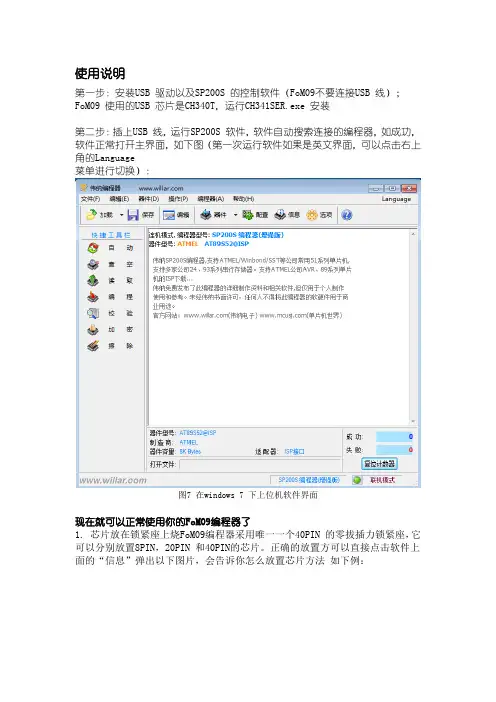
使用说明第一步:安装USB 驱动以及SP200S 的控制软件(FoM09不要连接USB 线);FoM09 使用的USB 芯片是CH340T,运行CH341SER.exe 安装第二步:插上USB 线,运行SP200S 软件,软件自动搜索连接的编程器,如成功,软件正常打开主界面,如下图(第一次运行软件如果是英文界面,可以点击右上角的Language菜单进行切换):图7 在windows 7 下上位机软件界面现在就可以正常使用你的FoM09编程器了1. 芯片放在锁紧座上烧FoM09编程器采用唯一一个40PIN 的零拔插力锁紧座,它可以分别放置8PIN,20PIN 和40PIN的芯片。
正确的放置方可以直接点击软件上面的“信息”弹出以下图片,会告诉你怎么放置芯片方法如下例:下面以烧写一片AT89S52 为例,介绍FoM09的使用方法及烧写步骤:第一、将一片AT89S52 芯片放入编程器锁紧插座,压下手柄锁紧;第二、在软件中点击“器件”按钮,(例如:选择型号AT89S52(型号不要选错));第三、在软件中点击“加载”按钮,在“加载文件”对话框中找到找到你要烧写的文件,按默认点击确定即可;第四、点击“自动”编程。
(注意:“自动”编程的步骤,可以通过点软件上的“选项”后,选择你要执行的步骤)。
如果需要对单片机加密,请点击“配置”按钮,弹出器件配置框后设置加密选项,对于AT89S52 通常选择“Mode 4”,然后执行“加密”操作。
在加密前可以执行“校验”操作检查程序写入是否正确。
如何烧写和复制24C 系列EEPROM:编程操作和和上述AT89S52 的操作类似,如果使用自动编程功能,请取消自动选项里的“查空”选项,否则可能报错;24C 系列存储器没有擦除功能,如果要清空24 系列芯片,在未加载任何文件的情况下(即软件缓冲区为全FF,点击编辑按钮弹出的就是缓冲区,如果缓冲区中有数据,可以填充FF),点击编程按钮编程一次,芯片内的数据就被清空了(因为写入了全FF);如果要复制24c 系列芯片,在软件中选择对应的芯片型号,放上芯片后,点击“读取”按钮,再点击“保存”即可将芯片内的数据保存到电脑硬盘中。

WizPro200Nx(有数量控制功能) 编程器使用说明(For 瑞萨系列MCU)版本 1.01本烧写器支持的芯片:1.1Renesas Flash MCU R8C系列、M32C系列MCU,支持序列号功能。
序列号为4个字节长度,其在Flash中存放的地址可由用户通过PC应用程序随意设定,同时序列号的初始值和累加量也由用户自己随意设定;2特点:2.1支持瑞萨(Renesas) R8Cxx系列MCU,包括:R8Cxxx、M16Cxx、M32Cxx系列等;2.2支持UART编程接口;2.3支持3.3V和5.0V接口电平;2.4支持裸片烧写或在板烧写(In-Circuit-Program、On-Board-Program);2.5支持脱机烧写,烧写时无需连接电脑,方便生产线使用;2.6USB通讯接口,方便连接电脑的连接;2.7自动编程优化,编程速度快;2.8支持序列号的设定,地址任意选择;2.9支持烧写数量控制功能(针对方案开发公司该功能可以控制客户烧写的芯片数量,而保证方案公司的利益;2.10操作简单,单键触发,蜂鸣器和LED提示烧写的结果;2.11支持USB在线升级Firmware,便于器件的更新和扩展;2.12可整合成1拖n的烧写平台,满足大批量生产的需要;3外观接口图:4指示灯和蜂明器:2.1 电源指示灯:编程器接通电源后指示灯点亮,表示电源正常;2.2 状态指示灯(红色和蓝色LED灯):2.2.1:编程器通过USB连接到电脑时,打开编程器的PC软件时蓝色和红色的LED灯点亮,同时蜂鸣器响2次长声;2.2.2 编程器下载程序后接上电源时:¾红色和蓝色指示灯交替闪烁:表示系统正进行内部数据校验;¾红色灯亮同时蜂鸣器响2次长声:表示系统内部数据校验失败,须连接电脑重新下载 程序才可正常烧写;¾蓝色灯亮同时蜂鸣器响1次长声;表示系统内部数据校验成功,可以开始烧写芯片;¾蜂鸣器长响1声(约1秒钟):说明编程器内部的Firmware有问题,需到我司网站下载 最新的Firmware或联络我司(我司网址:)2.2.3 编程器完成校验后开始编程时:¾蓝色红色指示灯交替闪烁,表示编程器正在对目标芯片进行编程器;¾红色灯亮同时蜂鸣器响3次短声:表示对目标芯片编程器失败,请作相应检查;¾蓝色灯亮同时蜂鸣器响1次长声:表示对目标芯片编程成功;5按键和接口说明:5.1白色按键:编程器按键,按一下按键系统就开始对目标芯片编程;5.2电源接口:接9~12V DC Adapter,>300mA即可,随机配有一个DC电源适配器;5.3USB接口:用于进行下载程序或在线编程以及编程器内部数据的更新和设定;5.4编程接口:用于对MCU进行编程,排线中箭头指向的一端的为第一脚,注意排线的插入方向(有防呆设计)。

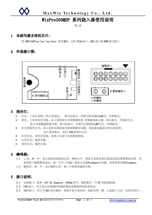
WizPro200MSP 系列烧入器使用说明V1.01本烧写器支持的芯片:TI MSP430F1xx/2xx/4xx/5xxx 系列MCU;支持JTAG接口、BSL接口和SBW烧写接口;2外观接口图:3指示灯:¾红灯:上电后系统工作正常则亮; 烧写结束后,若烧写错误则此LED亮,否则熄灭;¾黄灯:上电时此灯闪烁,表示系统进行内部数据检查,若数据校验正确。
此灯熄灭,否则此灯亮, 表示内部数据校验有错;烧写结束后,若烧写正确则此LED灯亮,否则熄灭: ¾红色和黄色灯亮:表示系统内部校验出错或数据有问题,须连接电脑进行相应的处理;进入通讯模式,此2个LED也同时点亮;¾红色灯亮, 黄色灯闪烁:系统正在进行内部数据校验;¾红色灯亮:编程失败;¾黄色灯亮:编程正确;4蜂鸣器:4.1上电:响一声,表示系统内部校验正常,响两长声,则表示系统内部出错或内部达数据校验出错,需要重新下载数据或设定;响一长声(约1S)则表示内部Firmware有问题,需要重新更新Firmware;4.2编程后:响一声,表示编程正常,响三声则说明编程失败;5接口说明:5.1电源接口:接9~12V DC Adapter,>300mA即可,随机配有一个DC电源适配器;5.2USB接口:用于进行在线编程和编程器内部数据的更新和设定;5.3编程接口:用于对MCU进行编程,排线中箭头指向的一端的为第一脚,注意插入方向(有防呆设计)。
5.4JTAG接口信号说明 TDO/TDI TDI TMS TCK GND RESET NIL 引脚 1 3 5 7 9 11 13引脚 2 4 6 8 10 12 14 信号说明 VOUT NIL NIL TEST NIL NIL NIL Note:1.若使用MCU板自己的电源,VOUT(引脚2)可以不接;2.NIL的引脚请不要连接任何信号。
5.5 BSL接口信号说明 RxD TxD NIL TCK GND RESET NIL引脚 1 3 5 7 9 11 13引脚 2 4 6 8 10 12 14 信号说明 VOUT NIL NIL TEST NIL NIL NIL1.RxD 为编程器的接收,TXD为编程器的发送;2.若使用MCU板自己的电源,VOUT(引脚2)可以不接;3.NIL的引脚请不要连接任何信号。
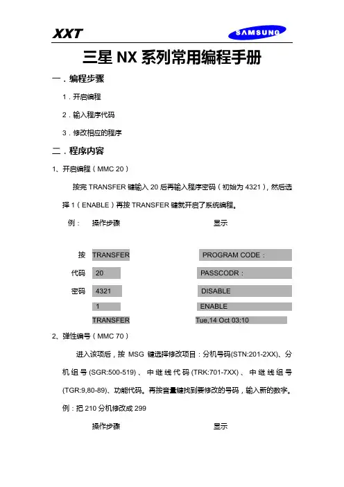
三星NX系列常用编程手册一.编程步骤1.开启编程2.输入程序代码3.修改相应的程序二.程序内容1、开启编程(MMC 20)按完TRANSFER键输入20后再输入程序密码(初始为4321),然后选择1(ENABLE)再按TRANSFER键就开启了系统编程。
例:操作步骤显示按TRANSFER PROGRAM CODE:代码20 PASSCODR:密码4321 DISABLE1 ENABLETRANSFER Tue,14 Oct 03:102、弹性编号(MMC 70)进入该项后,按MSG键选择修改项目:分机号码(STN:201-2XX)、分机组号(SGR:500-519)、中继线代码(TRK:701-7XX)、中继线组号(TGR:9,80-89)、功能代码。
再按音量键找到要修改的号码,输入新的数字。
例:把210分机修改成299操作步骤显示按TRANSFER PROGRAM CODE:代码70 STN09:201:+ STN22:210:分机号299 STN22:210:299存储MESSAGE SGR01:500:3、服务等级(MMC 30)进入该项后,按音量键选择分机,再输入两位数,第一位数代表白天服务等级,第二位数代表晚上服务等级。
等级A------没有限制等级B------根据B等级禁止/允许码表等级C------根据C等级禁止/允许码表等级D------根据D等级禁止/允许码表等级E------根据E等级禁止/允许码表等级F------只能打分机等级A.B.C.D.E对应按键1.2.3.4、例如;把202该成AC等级操作步骤显示按TRSF PROGRAM CODE代码30 201;AA4.等级限制码(MMC 60)进入该项后,按音量键,再输入新的限制码,然后按重拨键输入0或者1来选择限制的等级。
0:无限制,1:限制.例:限制B等级,只需将B下面的0改成1就行了。
5、设置外线振铃(MMC 43)进入该项后,用音量键选择外线,用MSG键选择振铃模式和白天晚上的振铃分机或分机组。


GROUP OF COMPANIESINSTALLER MANUALELECTRIC FENCE ENERGISERINTRODUCTION (3)DISCLAIMER (3)MOUNTING / BATTERY REPLACEMENT PROCEDURES (4)CONNECTION TO THE FENCE (5)CONNECTION / CONFIGURATION DIAGRAM (6)PC BOARD REPLACEMENT PROCEDURES (7)SERVICE CONDITIONS (8)APPENDIX A…………………………………………………………………………………. 9-11I N T R O D U C T I O NThe WIZORD 4 is a battery (12V 7AH nominal) operated energizer suitable for connection to mains (230V 50Hz nominal).The batteries to be used are rechargeable lead-acid batteries. Non-rechargeable batteries must NOT be used. The lead-acid batteries require venting and it is imperative that the energizer be situated in a well-ventilated area.D I S C L A I ME RNEMTEK Holdings (Pty) Ltd or any of its subsidiary companies does not guarantee that the operation of the product will be uninterrupted or totally error free.Energizer specifications may be altered without prior notification.The installer is referred to the definitions and general requirements in Appendix A.The installer must take into consideration the applicable municipal laws concerning the installation of electric fences. General guidelines are available, or refer to the website: . International standards can be viewed at http://www.iec.ch and South African standards on http://www.sabs.co.za.*Energizer to be mounted vertically against a flat surface, in well ventilated area.OPTION 1: NO EARTH LOOP MONITORINGBridge the earth OUT to earth RETURN. The unit will now function as per theold version WIZORD.OPTION 2: EARTH LOOP MONITORING; GOOD SOIL EARTHINGOPTION 3: EARTH LOOP MONITORING; POOR SOIL EARTHING EARTHFEARTHFJUMPER OPERATION:Jumper Description: Inserted: Removed:JP1 Switch input enabled See next tableJP2 Switch input delay (4 minutes) Switch input instantaneous Jumper Description: Inserted: Removed:JP1 See previous table Remote on/off enabled JP2 Plastic tab switch enabled Plastic tab switch disabled * JP3 – Reserved for future use* JP4 – Bypass safety switch. Not to be installed during normal use.terminals if connected PC Board back) into place the PC Board into place.Also ensure that the opto-coupler PC Board REMOVAL: REPLACEMENT:S E R V I C E C O N D I T I O N SOn removing the energizer lid and disconnecting JP3, one or more of the following service conditions may be displayed (Lit LED):FUSE DESCRIPTION & FAULT SYMPTOMSHOW TO CHECK: (ALL FUSES ARE 2 AMPERE FAST BLOW)F1: Energizer does not operate when mains is switched offF2: Siren or strobe light does not operate (ensure that the unit wasswitched off with no fault conditions)F3:Power light is not lit, even when mains is presentGOODSystem TimeoutFence Interference Over-temperature Energizer Faulty or Tampered withBattery Flat SERVICEBASIC DEFINITIONS:Electric Fence: a barrier which includes one or more electric conductors, insulated from earth, to which electric pulses are applied by an energiserConnecting Lead: an electric conductor, used to connect the energiser to the electric fence or the earth electrodeElectric Security Fence: a fence used for security purposes which comprises an electric fence and a physical barrier electrically isolated from the electric fencePublic Access Area: any area where persons are protected from inadvertent contact with pulsed conductors by a physical barrier.Pulsed Conductors: conductors which are subjected to high voltage pulses by the energiser.Secure Area: an area where a person is not separated from pulse conductors below 1,5m by a physical barrier.GENERAL REQUIREMENTS FOR ELECTRIC SECURITY FENCES:Electric fences shall be installed and operated so that they cause no electrical hazard to persons, animals or their surroundings.Electric fence constructions which are likely to lead to the entanglement of animals or persons shall be avoided.An electric fence shall not be supplied from two different energizers or from independent fence circuits of the same energiser.For any two different electric fences, each supplied from a different energiser independently timed, the distance between the wires of the two electric fences shall be at least 2m. If this gap is to be closed, this shall be effected by means of electrically non-conductive material or an isolated metal barrier.Barbed wire or razor wire shall not be electrified by an energiser.Any part of an electric fence which is installed along a public road or pathway shall be identified at frequent intervals by prominently placed warning signs securely fastened to the fence posts or firmly clamped to the fence wires. The size of the warning signs shall be at least 100mm x 200mm. The background colour of both sides of the warning plate shall be yellow. The inscription on the plate shall be black . The warning sign shall typically appear as depicted in Figure x. The inscription shall be indelible, inscribed on both sides of the warning plate and have a height of at least 25 mm.Warning signs shall be placed at- each gate- each access point- intervals not exceeding 10m- adjacent to each sign relating to chemical hazards for the information of emergency services.Gates in electric security fences shall be capable of being opened without the person receiving an electric shock.The energiser earth electrode shall penetrate the ground to a depth of at least 1m. The distance between any electric security fence earth electrode and other earth systems shall not be less than 2m.Connecting leads that are run inside buildings shall be effectively insulated from the earthed structural parts of the building. This may be achieved by using insulated high voltage cable.Connecting leads that are run underground shall be run in a conduit of insulating material or else insulated high voltage cable shall be used. Care shall be taken to avoid damage to the connecting leads due to external factors.Connecting leads shall not be installed in the same conduit as the mains supply wiring, communication cables or data cables.Connecting leads and electric fence wires shall not cross above overhead power or communication lines.Mains supply wiring shall not be installed in the same conduit as signalling leads associated with the electric security fence installation.Crossings with overhead power lines shall be avoided wherever possible. If such a crossing cannot be avoided, it shall be made underneath the power line and as nearly as possible at right angles to it.If connecting leads and electric fence wires are installed near an overhead power line, the clearances shall not be less than those shown in Table 1. Power Line Voltage (V) Clearance(m)Equal or less than 1 000 3>1 000 and equal or less than 33 000 4>33 000 8Table 1If connecting leads and electric fence wires are installed near an overhead power line, their height above the ground shall not exceed 3m.11 Where an electric security fence passes below bare power line conductors, the highest metallic element shall be effectively earthed for a distance of not less than 5m on either side of the crossing point.This height applies either side of the orthogonal projection of the outermost conductors of the power line on the ground surface, for a distance of- 2m for power lines operating at a nominal voltage not exceeding 1 000 V- 15m for power lines operating at a nominal voltage exceeding 1 000V Electric security fences and their ancillary equipment shall be installed, operated and maintained in a manner that minimizes danger to persons, and reduces the risk of persons receiving an electric shock unless they attempt to penetrate the physical barrier, or are in a secure area without authority. Exposed conductive parts of the physical barrier shall be effectively earthed. A spacing of 2.5 m shall be maintained between uninsulated electric fence conductors or uninsulated connecting leads supplied from different energizers. This spacing may be less where conductors or connecting leads are covered by insulating sleeving, or consist of insulated cables, rated to at least 10kV.This requirement need not apply where the separately energized conductors are separated by a physical barrier, which does not have any openings greater than 50mm.A vertical separation of not less than 2m shall be maintained between pulsed conductors fed from different energizers.Ensure that all ancillary equipment connected to the electric security fence circuit provides a degree of isolation between the fence circuit and the supply mains equivalent to that provided by the energiser. Protection from the weather shall be provided from the ancillary equipment unless this equipment is certified by the manufacturer as being suitable for use outdoors, and is of a type with a minimum degree of protection IPX4.。
WizPro100系列 FlashMCU 编程器PC 应用程序操作手册版本1.01. 主窗口:对于不同的产品类型,其显示会有所不同;¾ 对于不同的产品型号,其显示的内容和细节会有所不同;¾ 对于同一种产品型号,当选择的具体芯片不同时,其参数配置的页数和内容页会不一样; ¾ 编程接口的选择需根据芯片的厂家和型号进行选择,系统本身会根据芯片的型号进行一定的设定;¾ 产品信息栏仅供参考,对芯片的编程操作没有任何影响; ¾ 有的系列的产品可能还提供序列号的支持和烧写次数的控制功能;目标二进制数据显示区域。
操作按钮区,点击进行功能的执行。
编程器名称显示区,指示当前的设备连接情况。
信息显示区,显示各种操作的信息和结果。
芯片设定和选择,对不同的型号其内容和页数页会不同。
2.操作按钮的功能说明:¾要操作相应的功能时,将鼠标移至相应的按钮处,则按钮就会自动突起,点击即可;¾所有按钮具有即时提示功能,只要将鼠标移至按钮处并停顿1S就能显示提示信息;¾:点击该按钮关闭并退出此应用程序;¾:从目标二进制文件中获取数据;该数据即是需要写入到目标MCU中的程序代码;¾:用于将目标二进制文件的内容转存为标准的二进制数据文件(BIN文件);¾:将目标二进制数据及相关的配置数据下载到WizPro100编程器中,以便于脱机进行烧写(不再需要连接电脑);¾以下4个按钮的功能只用于PC在线的操作,主要为方便开发人员的使用。
该功能不影响已下载到WizPro100编程器中的数据和配置;而是直接透过WizPro100进行MCU的操作,但是在进行操作之前,同样需进行芯片的选择和参数的配置;¾:用于擦除MCU中Flash的全部内容,对不同的厂家的芯片其擦除的具体要求会有所不同,系统会根据芯片的的配置参数进行操作;¾:检查目标MCU中的Flash内容是否已被完全擦除;¾:将目标二进制数据写入到MCU的Flash中,对同一个目标代码,在编程中出错时,可重复编程而无须再擦除,对不同的数据则必须先擦除;否则系统会提示数据写入错误;¾:验证数据是否完整地写入到MCU的Flash中,如写入成功后,则写入相应的配置和保护数据以便对目标数据进行读保护,否则提示编程校验错误;¾在线编程的一般步骤如下:i.点击按钮来擦除MCU Flash中已有的内容;ii.点击按钮来确认擦除是否成功,若芯片不为空,则回到第一步再擦除;iii.芯片为空后,点击按钮启动编程功能;系统会弹出一个进度窗口指示编程的进度;iv.编程成功后,点击按钮进行数据的验证和参数的配置及保护的执行;3.芯片的选择.见图所示:¾请单击按钮,系统会出现如图所示的芯片的型号和系列显示菜单(注:对不同的厂家和芯片,其显示的方式和细节会不同,此图仅显示只对ST72Fxx系列MCU而言,产品型号WizPro100S7);¾根据实际使用的芯片的型号,点击对应的菜单栏目,选择好芯片,对于未有列出的芯片型号,则可选择具有同样RAM/ROM大小的一款来代替;¾选择完成后MCU型号一页则会显示相应的芯片的名称及对应的Flash ROM的大小等信息;¾MCU型号选择完成后,系统会根据不同的MCU的特点显示相应的参数配置页,用户必须对该参数进行正确的配置和设定,否则会影响到MCU的正常的运行;具体的参数的选择和设定查看相应的MCU的DataSheet及相关的厂家的资料;4.加载目标二进制文件. 如图所示:¾点击按钮,系统会出现如图的弹出窗口,选择对应的文件点击并打开;¾对于不同产品和芯片,其所对应的文件的格式会不同,本系统目前支持如下的二进制文件格式:Intel HEX, Motorola S19, Binary文件,MSP430的TXT和A43文件格式等;¾加载文件完成后,“下载”及在线操作按钮(“擦除”、“查空“、“编程”及“校验”)将被激活,意味可以进行相应的功能操作;5.通讯口的选择(“串口配置”):如图所示¾该编程器采用USB虚拟串口进行数据的通讯,当编程器通过USB连接到电脑时,电脑会根据实际情况创建一个动态的串口;¾点击选择“串口配置”页进入该配置窗口;¾首先点击“”按钮,刷新系统的串口列表;¾点击选择窗口的箭头来选择编程器所对应的串口,该窗口会将系统所有的串口列出,对于本编程器来讲,一般会对应到具有最大串口编号的一个;点击选择它,比如,图示的“COM20“;¾点击按钮来查找已连接的编程器,若串口选择正确,且编程器已连接,则系统会显示编程器的产品型号代替“未发现烧写器,请检查通讯口”显示,如下图所示;¾若仍然显示“未发现烧写器,请检查通讯口”信息,则选择不同的串口在查找,直至找到已连接的编程器;¾编程器USB拔掉后再连接时,必须执行如上的操作,否则系统会出现操作不正常现象;¾此图示显示了设备正常连接时的信息,如“WizPro100ST7x, MaxWiz Technology;¾由于选择了具体的芯片,ST7FAudioAR9,所以看到了“芯片配置”页;该配置数据必须根据芯片的资料来进行设定和选择;6.目标数据的下载:¾点击按钮,将目标数据下载到编程器内部的存储器中,下载完成后,编程器哔一声,同时系统显示下载成功信息窗口;¾该功能会将所有的目标数据及芯片和编程器接口配置及辅助的信息下载到编程器的内部存储器中,不正确的参数和配置可能会影响到编程器的编程功能;因此下载前必须认真核对相应的数据;¾下载完成后,编程器必须重新上电方可进行编程操作,此时编程器无须再与电脑进行连接,其只需电源即可独立完成所有的设定的操作和编程;具体方法见产品的使用说明;。
e-Writer( ) (HOPE3000) ( e-Writer e-Writer 4P Jumper [ 4P DIP Switch ] )HOPE3000 HOPE3000 HOPE3000 HOPE3000HOPE3000 MS Windows HOPE3000 – DOS Command Modee-WriterPro LCD e-Writer plus e-monitor( LCM ) e-monitor e-monitorA HOPE3000 e-monitorBC e-Writer e-WriterD e-WriterPro ICP ICP ICPE e-WriterPro CN3 CN3 e-WriterPro( Writer) e-Writer e-Writer e-Writer plus e-WriterPro e-Writer e-Writer e-Writer plus e-Writer plus e-WriterPro e-WriterPro1.00 2009/03/111.01 2009/04/301.02 2009/06/151.03 2009/10/15 1. HOPE30002. HOPE30003. N-14.1.04 2010/01/20 Memory IC1.05 2010/04/29 1. e-Writer plus2. Memory IC3. HOPE30004.1.06 2011/01/12 1. ( )2. Dos Command Mode T3. Dos Command Mode E SPI Flash4. Pin Configuration5. DOS -C6. Dos Command –D EEPROM (.MEM) MCUEEPROM1.07 2011/01/14 1. Dos Command Mode P V B2.HOPE30001.08 2011/05/06 e-WriterPro1.09 2012/05/30 1. Dos Command Mode D IC2. Dos Command Mode S1.10 2012/07/10 1. ICP ( Case11) ICP ( D)2. HOPE3000 IC3. HOPE3000 V1.04 ( )4. e-WriterPro CN3 ( E)5. HOPE30001.11 2013/05/22 1. Case3 IC2.Dos Command Mode console CON Q1.12 2013/12/23 (6) (7) (7) (10) (10) (14) (17) (17)Case. 1 – MCU (17)Case. 2 – (19)IC (21)Case. 3 –Case. 4 – (23)Case. 5 – (25)Case. 6 – IC ( ) (26)Case. 7 – (28)Case. 8 – PC (Firmware) (29)Case. 9 – (31)Case. 10 – e-WriterPro (35)Case. 11 – e-WriterPro ICP(In-Circuit Programing) (37)HOPE3000 (38) (39) (39) (39) (39) (40) (40) (41) (42) (43) (44) (45)IC (45)HOPE3000 (46)IC (47) (47) (48) (49) (50) (52)HOPE3000 – Dos Command Mode (56) (56) (57) (62)e-monitor (64)e-monitor (65)e-monitor (66)e-monitor (67)e-monitor (67)A (70) (70)Writer (73)e-monitor (75)B (78)C e-Writer (79)D e-WriterPro ICP ICP (81)E e-WriterPro CN3 (87)e-Writer ( ) (MCU) OTP/Flash MCU(Program) (Data)PC PC PC HOPE3000 PC USB cable PC HOPE3000MCU MCU e-WriterPro e-Socket e-Writer e-Writer plus (Adaptor)( Writer) e-Writer e-Writer e-Writer plus e-WriterPro e-Writer e-Writer e-Writer plus e-Writer plus e-WriterPro e-WriterPro1USB Port (PC)( )MS Windows 2000/XP ( ) HOPE3000 ( )e-WriterPro1-1e-Writer pluse-Writer plus ( 1-2) ( 1-3)1-21-3e-Writer1-41. e-monitor – LCM e-Writer plus 6 e-monitor1-5USB cable USB ( 1-6) e-Writere-Writer 4P Jumper ( 4P DIP Switch) ( 1-1 )1-61HOPE3000 “HOPE3000V304Build20120316Install.EXE” ( release )2( 1-7) (Next)1-73HOPE3000 ( 1-8) (Next)1-84( 1-9) (Next)1-95( 1-10) (Next)1-106Install ( 1-11)1-117Finish ( 1-12)1-121-13(e-WriterPro) 1-14(e-Writer plus) 1-15(e-Writer)1-21-141-13LCD: e-Writer 4P DIP Switch 1-13OKReady/Busy /FailUSB USB PC( )5V ( )4P Jumper (DIP Switch) ( ) 1e-WriterDC 9V~16V DC e-Writer plus e-monitor e-monitor e-Writer plus LCD e-WriterPro LCD e-WriterPro Handler Handler e-WriterPro e-WriterPro 1 4P Jumper ( 4P DIP Switch) Short (Switch ON) SPIFlash MCU( HT83Fxx) OTP/Flash MCU Open1-151-16(Switch OFF)e-Writer4P Jumper ( 4P DIP Switch)1-2e-Writer/e-Writer plus 1-3e-WriterPro PinAD0 (ICPDA)8 HT46&HT48 Flash MCU AD1 (ICPDA) 6 HT46&HT48Flash MCUAD2 4AD3 2CLK (ICPCK)10CSB 12RWB 14SCL 3SDA 5VDD 18VPP20SCK 9 1SDI 11 2SDO 13 3CEB 15 4Ground (direct connection)16 17 19(VSS)1: 4P Jumper Jumper 4 Short = SCK , Open = Ground (direct connection)) (4P DIP Switch DIP 4 ON = SCK , OFF = Ground (direct connection))2: 4P Jumper Jumper 3 Short = SDI , Open = Ground (direct connection)(4P DIP Switch DIP 3 ON = SDI , OFF = Ground (direct connection))3: 4P Jumper Jumper 2 Short = SDO , Open= Ground (direct connection)(4P DIP Switch DIP 2 ON = SDO , OFF = Ground (direct connection))4: 4P Jumper Jumper 1 Short = CEB, Open = Ground (direct connection)(4P DIP Switch DIP 1 ON = CEB, OFF = Ground (direct connection))1-32MCU HT-IDE3000 Project Build MCU (.OTP/.MTP/.PND.. ) HOPE3000 MCU HT-IDE3000 HT-IDE3000PC HOPE3000MCUCase. 1 –PC MCU (.OTP/.MTP/.PND) MCU 1HOPE3000 / / ( 2-1)2-122-2 (OTP MTP PND)( 1) ( 2) ( 3)2-23( \ \ ) 2-32-3e-WriterPro ( 2-4)2-44( 2-5)2-4 IC ( IC ) Flash MCU MCU3 HOPE3000A2-5Case. 2 –Case. 1 PC HOPE3000 PC1 ~ 3Case. 1 1~342-6 2-75( 2-7) ( 1 2)( 3)2-62-762-7 ( )3 HOPE30004 HOPE3000AICCase. 3 –IC1 ~ 4Case. 2 1~452-8 ( 1) ----> ( 2) ( 3) Code( 4) ( 5) 2-92-862-9 ( 1) ROM ( 2) ( 3) ( 4)2-975~6 IC 2-10 ( 1) ( 2)3 HOPE30004 HOPE3000A2-10Case. 4 –Program ROM1~4Case. 2 1~452-11 1~3 ( 4) 2-1262-12 IC Program ROM 100H N+1 N 22( IC 22 23 …) 1~32-12 HOPE30002-1272-13 1 2 ( 3) 22-13Case 33 HOPE30004 HOPE3000ACase. 5 –( PC ) PC1~5Case2 1~56HOPE3000 PC USB71~5 (Ready LED ) (Fail LED ) ( 1~5)LED (Ready )8IC( 1~5 MCU ) ( 1-13~1-15 )9LED ( / LED LED )e-WriterPro e-Writer e-Writer plus3 HOPE30004 HOPE3000ABIC (Case. 6 –)IC IC IC IC IC HOPE3000 IC1/ / IC 2-142-142IC IC IC( 2-15)2-15e-WriterPro ( 2-16)2-163HOPE3000 IC Driver 2-17 IC / / IC HOPE30002-17HOPE3000 A Case. 7 –HOPE3000 DOS Command Mode1HOPE3000 Microsoft Windows HOPE3000 DOS Command Mode2HOPE3000 ( 3 ) DOS Command Mode WCMD.EXE ( 2-18)2-183DOS Command Mode ( 2-19 )2-19DOS Command Mode HOPE3000 - Dos Command Mode A(Firmware)Case. 8 – PCe-Writer plus( ) PC HOPE3000 ( HOPE3000 )e-Writere-Writer plus e-WriterProPC1/ /F/W ( 2-20 )2-2022-212-2132-222-23 HOPE3000 2-234F/W ( 2-24) HOPE30002-24HOPE3000 ACase. 9 –e-WriterProe-WriterProe-Writer e-Writer plus1/ /2-252-2522-26 ID62-2632-27 e-Mail( )HOLTEK2-2742-28 2-27 3 HOLTEK2-285HOLTEK e-Writer Pro Registry Key2-292-30 ( )2-306HOPE3000 ( 2-31 1)2-3172-326 1 HOLTEK2-32HOPE3000 ACase. 10 – e-WriterProe-WriterPro e-WriterPro e-WriterPro e-WriterPro e-WriterPro< 1>e-WriterPro CN3 Pin2/Pin4 2-33 2-342-332-34< 2>e-WriterPro 2-351)2-35E – e-WriterPro CN3 BIN1~BIN7 Pin & 42) &2-36T1 e-WriterPro 10ms < T1 < 500msT2 e-WriterPro 12ms < T2 < 100ms1) e-WriterPro J7( 3-37 ) e-WriterPro2-372) EXTG Pin 2-36 T1(e-WriterPro )3) 2 EOP Pin (Polling) 2-36 T24) EOP ( 2-36 T2 ) BIN1~BIN7 PinBIN1 T2 (Low) BIN4 T2 ICe-WriterPro ICP(In-Circuit Programing)Case. 11 –e-WriterPro ICP1ICP (e-WriterPro 1-1) e-WriterPro CN1( D – e-WriterPro ICP ICP )2HOPE3000 (.OTP/.MTP/.PND) / /32-38 ICP( D e-WriterPro ICP ICP 2-38 ICP HOPE3000 )2-384/ / …HOPE3000 De-WriterPro ICP ICPHOPE3000 HOPE3000 IC ( PC ) 3-13-13( 3-2 )OTP (OTP MCU)MTP (Flash MCU)PND (MCU with SPI Flash)APF (Advanced Programming File )R36 (HT81R36 )ICIC IC IC IC 3-12 IC( ) HOPE3000HOPE3000 ( )HOPE3000HEXHOPE3000 Intel HEXHOPE3000/ / (3-3)( 3-4)/ ICe-WriterPro IC / /3-33-2HOPE3000// /( 3-5 )F/WPC Case. 8 PC OptionIC OptionHT-IDE3000 ( )/ /( 3-6 )e-WriterIC ICHOPE3000 3-7 1 HOPE3000 Release Driver 2 (Firmware) ID3-73-5 3-63-4Code( Program), Option, Data, Voice ROM 3-8 ROM ROM ---- IC ROM ( ) HOPE3000 HOPE3000ROMHOPE3000ROM , / IC HOPE3000 HOPE30003-8( 3-9)IC Windows 0( ) F/W( e-WriterPro)3-93-10 DriverDriver Driver( ) Driver IC / / IC IC 3-10 Driver HT45F0V Driver 1.0 Driver IC Driver IC IC Driver DriverROM ROM Code Code Code + Option Code Option Code + Option + Data Code Option Data OTP/MTP/PNDV1.04 ( ) V1.04 ROMV1.04( ) ( ) Option ROM TRIM (HIRC/LVR .. ) ROM ( IC TRIM IC HOPE3000 IC IC TRIM ) 3-10( IC ) 3-11IC ( IC )IC IC ICIC IC IC IC ICIC IC Flash Type MCU ICIC / / HOPE3000 HOPE3000 ( ) / /HOPE3000Flash Type MCU ICDataData ROM IC SPI Flash MCU( HT83Fxx) ( IC SPI Flash) IDIC 3-11IC ( IC ) OTP MCUIC / / IC ( 3-12) IC ICIC IC IC ( 3-12 HT45R0F ) ICICIC3-12HOPE3000 HOPE3000 ( PC IC ) ( PC ) ( ) 4-14-1 4ICIC ( 4-2 )Driver HOPE3000 Driver IC \ \ IC ICHOPE3000 IC 04-2( 4-3)(.SPC)(.SPC)HOPE30004-3( ) ( ) ( 4-4)4-4ID — HOPE3000 IDIC OTP MCU ICIC ( IC ) -----> <-----4-4 Code Optiion Data Voice —IC Code Option Data Voice ROM Code Voice( 4-6) ( 4-4 Voice) IC ROM—( 4-9)4-5( )4-5。
使用手册 ·2005年4月安全指导:须注意警告提示以确保人身安全,保护产品及相关设备不受损坏。
这些警告提示均附带警告级别说明。
资质人员:本设备/系统须根据此手册进行安装和运行。
根据已有安全惯例和标准,只有具备资质的人员有权进行安装和操作此设备。
版权归西门子(中国)有限公司所有 免责申明装订版和电子版中均有此文档。
我们鼓励用户购买有授权的装订手册或者查看西门子(中国)有限公司设计和授权的电子版手册。
西门子(中国)有限公司对装订手册或电子版部分或全部内容的拷贝一律不负任何责任虽然我们对手册内容是否与仪表描述一致进行了核对,但仍可能存在变动。
这样我们不能确保完全一致。
手册内容会被有序的核查并纠正,勘误表登录在后续版本里。
我们欢迎用户提出各种改进建议。
技术数据可能有变动z 要查看西门子过程仪表手册,请进入/pi警告:此产品只有在正确运输、储存、安装、装配、操作及维护的情况下才能正确和安全的工作。
注意:请根据说明书使用本产品。
目录MultiRanger 100,200 (1)MultiRanger 100 (1)MultiRanger 200 (1)本手册 (1)手册符号 (2)配置举例 (2)规格 (3)安装 (8)安装 (8)安装场所 (9)安装说明 (9)墙装 (9)通过导管走线 (10)嵌板安装 (11)盘装 (12)MultiRanger母板 (13)安装电池 (13)安装SmartLinx 卡 (14)可选择设备 (14)接线 (15)端子板 (16)电缆 (16)探头 (17)继电器 (17)温度传感器 (18)mA 输入[MR 200] (18)mA 输出 (18)物位系统同步 (19)电源 (19)数字通信 (20)RS-232 串行连接 (20)RS-485串行连接 (20)离散输入 (20)MultiRanger 的运行 (21)运行模式 (21)运行模式中的读数 (22)状态参数 (23)显示的控制 (24)调整主要读数以适合四位LCD (24)辅助读数 (24)多种读数[仅MR200] (25)编程模式 (26)开始编程模式 (26)手操器 (26)手操器按键 (27)Dolphin Plus (28)Dolphin Plus 工具栏按钮 (29)SIMATIC 过程设备管理器(PDM) (30)设备描述 (30)激活MultiRanger (31)改变参数 (31)安全 (32)采用单位或百分比(%) (32)参数类型 (32)显示读数 (34)改变参数(Dolphin Plus) (34)参数索引 (35)主索引和二级索引 (36)主索引 (36)二级索引: (36)开始测量 (37)单点模式 (37)平均值或差值[仅MR200] (38)双点模式 (38)平均值或差值[仅MR200] (39)测量条件 (39)响应速度 (39)尺寸[仅MR200] (39)失效状态保持 (39)继电器 (40)概括介绍 (40)继电器功能 (40)报警 (40)泵 (41)各式混合 (41)继电器状态—非运行模式 (42)继电器状态 (42)继电器相关参数 (42)继电器配线测试 (43)继电器激活 (43)继电器失效状态保持 (44)预设置应用 (45)优先的物位备份 (46)优先的物位备份的参数 (46)离散输入 (47)离散输入配线 (47)离散输入逻辑编程 (47)mA I/O (48)mA输入[MR 200] (48)mA输出 (48)体积[MR 200] (50)读数 (50)容器形状和尺寸 (50)特性表[MR 200] (51)例表 (51)只用于MultiRanger 200 (52)报警 (53)物位 (53)设置简单的物位报警 (54)速度[MR 200] (54)范围内/范围外报警[MR 200] (55)电缆故障 (55)温度[MR 200] (55)回波丢失(LOE) (56)泵的控制 (57)设置泵抽水参数组 (57)设置泵抽水(入蓄水池)参数组 (58)其它泵控制算法 (60)设置继电器为可变的任务接力模式[MR 200] (60)设置继电器实现固定的任务协助模式 (60)设置继电器实现固定的任务接力模式[MR 200] (61)设置继电器为可变的任务工作模式[MR 200] (61)设置继电器为先入先出(FIFO)协助模式[MR 200] (62)可选择的泵控制 (62)由物位变化率启动泵[MR 200] (62)根据工作比率使泵轮流工作[MR 200] (63)累计泵的抽取体积[MR 200] (64)设置独立的失效状态保持控制 (64)设置一个泵进行运转[MR 200] (65)设置泵的启动延迟[MR 200] (65)减轻墙壁附着[MR 200] (65)对泵分组[MR 200] (66)设置一个奔流阀[MR 200] (67)通过通信控制继电器 (67)跟踪泵的使用 (67)格栅控制[MR 200] (68)设置对隔栅的控制 (68)设置常用参数 (69)设置继电器1(操作隔栅) (69)设置继电器2到4(物位报警) (69)外部累加器和流体取样器[MR 200] (70)继电器触点 (70)累加器 (70)流体取样器 (71)基于体积和时间 (71)明渠监测(OCM)[MR 200] (72)常用参数 (72)设置水头零位 (73)设置累加体积 (74)MultiRanger 200支持的应用 (74)BS-3680 / ISO 1438/1 薄金属板V型切口堰 (74)BS-3680 / ISO 4359 矩形槽 (75)Palmer Bowlus 槽 (76)H型槽 (77)带有指数流量的PMD (78)适用的堰外形 (78)不适用的堰外形 (79)Parshall 槽 (79)Leopold Lagco 槽 (80)收喉槽 (81)通用计算支持 (82)典型流量特性 (83)槽示例 (83)堰示例 (83)测试配置 (85)仿真 (85)仿真一个简单的测量 (85)对一个物位周期进行仿真 (85)校验体积特性描述[MR 200] (86)校验OCM流量特性描述[MR 200] (86)I/O校验 (87)应用测试 (87)MultiRanger 通信 (89)MultiRanger 通信系统 (89)可选择的SmartLinx卡 (89)通信系统 (90)通信端口 (90)Modbus (91)SmartLinx (91)Dolphin Plus (91)接线指导 (92)端口1和2 (92)端口1和2:RS-232 RJ-11插孔和RS-485位置 (92)端口1:RS-232 RJ-11插孔 (93)端口2:RS-485 (93)配置通信接口(参数) (94)Modbus 寄存器规约 (97)字顺序(R40,062) (98)规约ID(R40,063) (98)产品ID(R40,064) (99)测量点数据(R41,010-R41,031) (99)累加值(R41,040-R41,043) (99)输入/输出(R41,070-R41,143) (100)离散输入(R41,070) (100)继电器输出(R41,080) (100)mA 输入(R14,090)[MR 200] (100)mA 输出(R41,110-41,111) (100)泵控制(R41,400-R41,474) (100)泵开设定点(R41,420-R41,425) (100)泵关设定点(R41,430-R41,435) (101)泵抽取体积(R41,440-R41,443)[MR 200] (101)泵工作时间(R41,450-R41,461) (101)泵启动次数(R41,470-R41,475) (101)参数读取(R43,998-R46,999) (102)参数索引 (102)索引参数存取区域 (102)读参数 (103)普通索引方法(P782=0) (103)参数特定索引方法(P782=1) (104)写参数 (104)普通索引方法(P782=0) (104)参数特定索引方法(P782=1) (104)格式字(R46,000到R46,999) (105)通用索引方法(P782=0) (105)参数特定索引方法(P782=1) (105)格式寄存器 (105)数据类型 (107)数字型数值 (107)位型数值 (107)无符号双精度整数(UINT32) (107)分离型数据 (108)文本信息 (109)继电器功能代码(P111) (110)Modbus响应 (112)错误处理 (112)通信故障诊断 (114)常规检查 (114)特殊检查 (114)通信附录A:单一参数读取(SPA) (115)图表 (115)读参数 (115)写参数 (116)格式寄存器 (116)错误代码 (117)参数参考 (119)MultiRanger 100 和 MultiRanger 200 (119)重要提示 (119)快速启动(P001到P007) (121)DPD和DPA编程[MR 200] (122)体积(P050到P055)[MR 200] (125)显示和读数(P060 到 P062) (129)物位跨跃备份 (131)失效状态保持参数(P070到P072) (133)继电器(P100到P129) (134)MutiRanger 200 (136)泵设定点修正(P121和P122)[MR 200] (141)独立继电器失效状态保持(P129) (142)高级泵控制修正(P130到P137)[MR 200] (143)奔流系统(P170到P173)[MR 200] (146)mA输出(P200到P219) (148)独立mA设定点(P210和P211) (150)mA输出限制(P212和P213) (151)mA输出修正(P214和P215) (152)mA输出实效状态保持(P219)[MR200] (153)mA输入(P250到P260)[MR200] (153)离散输入函数(P270到P275) (155)标准数据记录(P300到P321) (156)记录温度 (P300到P303) (156)记录读数(P304和P305) (158)泵记录(P309到P312) (158)流量记录(P320和P321)[MR200] (159)LCD累加器(P322和P323)[MR200] (160)波形记录(P330到P337) (161)自动记录ON/OFF设定点(P334到 P337) (164)装置记录(P340到P342) (166)明渠监控(P600到P621)[MR200] (167)样本指数 (169)泵抽取体积累加器(P622)[MR200] (176)累加器(P630到P645)[MR200] (177)量程标定参数(P650至P654) (180)温度补偿参数(P660至P664) (183)速度参数(P700至P708) (185)测量检验参数(P710到 P713) (189)探头扫描参数(P726至729) (192)显示参数(P730至P733) (193)SmartLinx 保留参数(P750到P769) (196)通信(P770到P782) (196)SmartLinx 硬件测试(P790到P795) (199)回波处理参数(P800到P807) (201)先进的回波处理(P815到P825) (217)高级TVT调整(P830到P835) (217)声波发射调整高级设置(P840-P852) (217)测试参数(P900到P913) (217)测量参数(P920到P927) (221)主复位(P999) (224)常用附录A:索引类型 (225)索引类型 (225)常用索引B — 技术参考 (226)传输脉冲 (226)回波处理 (226)TVT(时间变化阈值)曲线 (227)自动虚假回波抑制 (227)距离计算 (228)声速 (228)扫描 (229)体积计算[MR200] (229)通用,曲线[MR200] (230)流量计算 (230)通用,线形[MR200] (231)通用,曲线[MR200] (231)最大过程速度 (232)常用附录C:故障诊断 (233)常用故障表 (233)噪声问题 (234)确定噪声源 (235)非探头噪声源 (235)常见接线问题 (236)降低电噪声 (236)降低声噪声 (236)测量故障 (237)闪烁的LOE显示 (237)调整探头瞄准 (237)增加失效状态保持定时器值 (238)安装一个波束较窄的探头 (238)使用Dolphin Plus调试回波 (238)固定读数 (238)声束方向上的障碍物 (238)管嘴安装 (238)设置MultiRanger来忽略虚假回波 (239)错误读数 (239)错误读数的类型 (239)液体飞溅 (239)调整回波算法 (239)探头振铃 (240)设备维修和免责申明 (241)常用附录D:泵控制参考 (242)泵控制选项 (242)泵组 (242)速率对泵控制[MR200] (242)泵控制算法 (243)固定的任务协助模式(P110=50) (243)固定的任务接力模式(P111=51)[MR200] (244)可变的任务协助模式(P111=52) (244)可变的任务接力模式(P111=53)[MR200] (245)工作比率式的任务协助模式(P111=54)[MR200] (246)工作比率式的任务接力模式(P111=55)[MR200] (247)先入先出(FIFO)(P111=56)[MR200] (247)速率对泵控制(P121)[MR200] (247)其他泵控制[MR200] (247)常用附录E:更新软件 (249)更新软件 (249)常用附录F:升级 (250)安装一个MultiRanger100/200 (250)连接探头 (250)同轴探头扩展 (250)用RG62同轴扩展电缆连接探头 (251)MultiRanger Plus 到MultiRanger100/200参数 (252)常见附录G:Class1,Div2应用的导管进入 (253)MultiRanger 100和200MultiRanger 有两种类型可选,MultiRanger 100和MultiRanger 200,它们经过设计能满足各种应用。
伟纳SP200S编程器制作与使用一、简介SP200S编程器是伟纳电子继广受欢迎的SP180S编程器基础上改进设计的一款编程器,直接使用USB接口通讯和供电,体积小巧,软件和硬件设计成熟,功能完善,是目前唯一一款拥有专业编程控制软件的免费编程器。
可以支持ATMEL/WINBOND/SST公司常用的MCS51系列单片机,支持A TMEL/MICROCHIP/ST等公司24、93系列串行存储器。
增强版还具有标准的ISP下载接口,可支持A TMEL公司MCS51系列和A VR系列单片机在线下载编程(ISP)。
SP200S编程器不但可以满足单片机爱好者和开发人员学习和开发51、A VR单片机使用需求,也非常适合家电维修人员烧写93系列、24系列EEPROM的需求。
二、编程器硬件与软件特点硬件特点l体积小巧(仅一张名片大),使用携带非常方便l USB接口通讯及供电,通讯速度快,无须外接电源l内置CPU,烧写速度快,时序精准,不受计算机配置影响l功能完善,操作简单,硬件无须任何手动设置l单一40Pin锁紧座设计,同时支持8PIN,20PIN和40PIN的芯片l具有一个标准的10Pin ISP下载接口,轻松实现对用户目标板在系统编程SP200S编程器成品照片如下图(采用伟纳提供的DIY套件制作的带有ISP下载功能的编程器)软件特点l友好的界面,专业化全功能设计l强大的缓冲区编辑功能,支持复制、填充、逻辑运算、数据支持8位与16位显示l简体中文用户界面(即将推出多语言版)l支持WIN98SE/ME/2K/XP/Vista操作系统l系统配置要求低,运行稳定l编程命令丰富,包含编程、读取、擦除、查空、校验、加密(写锁定位)、读写熔丝位、读写配置位…l统计功能,自动统计烧写成功与失败的数量l自动序列号功能,适用于给产品写入唯一的ID数据l支持自动编程操作(相当于批处理),并可以自定义其操作内容l最近文件列表功能,可快速加载曾经使用过的文件l最近器件列表功能,可快速更改器件为近期使用过的其他器件l编程操作声音提示l文件更改自动重加载,适用于开发阶段快速更新芯片内容三、支持器件普通版(器件数量:68):可以支持A TMEL/WINBOND/SST公司的MCS51系列单片机,支持A TMEL公司24、93系列串行存储器。
1.0前面板功能B —一个标准B类USB连接器。
驱动程序在软件CD盘上,驱动是必须安装的。
2.RS232 —一个标准母DB9接口。
连接计算机只需一条RS232线.3.静音/mute (通道采单)按钮–用于输入通道和输出通道的静音或非静音。
当一条输入通道静音,红色的LED会被点亮用于指示。
当<< Menu 或Menu>> 键被持续按下, 然后按Mute按钮选择对应的通道。
在mute按钮下的LED被点亮和LCD出现通道菜单。
最后修改的菜单会出现在LCD上。
多条相同通道(输入/输出)可以被编成控制组。
通过编控制组很容易将多条通道的参数调为一样的参数。
多条输入通道可以编成控制组或多条输出通道编成控制组。
输入和输出不能被编成同一组。
4.通道菜单LED —指示通道被激活,可以修改数据。
5.峰值电平LED —显示信号当前的峰值电平: Signal, -12dB, -6dB, -3dB,Over/Limit(限幅). 输入Limit(限幅)LED指示设备的最大电平通行高度。
输出Limit(限幅)LED指示电平达到输出limiter (限幅器)的阀值)。
6.LCD- 显示所有用于控制需要的信息。
7.Menu(菜单)按钮- 具有6个menu(菜单)键:<<Menu (菜单向后), Menu>>(菜单向前), <<Cursor(光标向后), Cursor>>(光标向前), Enter/Sys/Speed(确定/系统菜单/加速), Exit(退出)。
每个键功能解译如下:<<Menu: 返回上一级菜单显示。
持续按住此按钮,然后用按对应通道Mute键。
这样就可以进入对应通道菜单。
(如按着<<Menu,然后按输入1的Mute,可进入通道1的功能菜单)Menu>>: 跳至下一级菜单显示。
持续按住此按钮,然后用按通道Mute键。
WizPro200Nx(有数量控制功能) 编程器使用说明(For 瑞萨系列MCU)版本 1.01本烧写器支持的芯片:1.1Renesas Flash MCU R8C系列、M32C系列MCU,支持序列号功能。
序列号为4个字节长度,其在Flash中存放的地址可由用户通过PC应用程序随意设定,同时序列号的初始值和累加量也由用户自己随意设定;2特点:2.1支持瑞萨(Renesas) R8Cxx系列MCU,包括:R8Cxxx、M16Cxx、M32Cxx系列等;2.2支持UART编程接口;2.3支持3.3V和5.0V接口电平;2.4支持裸片烧写或在板烧写(In-Circuit-Program、On-Board-Program);2.5支持脱机烧写,烧写时无需连接电脑,方便生产线使用;2.6USB通讯接口,方便连接电脑的连接;2.7自动编程优化,编程速度快;2.8支持序列号的设定,地址任意选择;2.9支持烧写数量控制功能(针对方案开发公司该功能可以控制客户烧写的芯片数量,而保证方案公司的利益;2.10操作简单,单键触发,蜂鸣器和LED提示烧写的结果;2.11支持USB在线升级Firmware,便于器件的更新和扩展;2.12可整合成1拖n的烧写平台,满足大批量生产的需要;3外观接口图:4指示灯和蜂明器:2.1 电源指示灯:编程器接通电源后指示灯点亮,表示电源正常;2.2 状态指示灯(红色和蓝色LED灯):2.2.1:编程器通过USB连接到电脑时,打开编程器的PC软件时蓝色和红色的LED灯点亮,同时蜂鸣器响2次长声;2.2.2 编程器下载程序后接上电源时:¾红色和蓝色指示灯交替闪烁:表示系统正进行内部数据校验;¾红色灯亮同时蜂鸣器响2次长声:表示系统内部数据校验失败,须连接电脑重新下载 程序才可正常烧写;¾蓝色灯亮同时蜂鸣器响1次长声;表示系统内部数据校验成功,可以开始烧写芯片;¾蜂鸣器长响1声(约1秒钟):说明编程器内部的Firmware有问题,需到我司网站下载 最新的Firmware或联络我司(我司网址:)2.2.3 编程器完成校验后开始编程时:¾蓝色红色指示灯交替闪烁,表示编程器正在对目标芯片进行编程器;¾红色灯亮同时蜂鸣器响3次短声:表示对目标芯片编程器失败,请作相应检查;¾蓝色灯亮同时蜂鸣器响1次长声:表示对目标芯片编程成功;5按键和接口说明:5.1白色按键:编程器按键,按一下按键系统就开始对目标芯片编程;5.2电源接口:接9~12V DC Adapter,>300mA即可,随机配有一个DC电源适配器;5.3USB接口:用于进行下载程序或在线编程以及编程器内部数据的更新和设定;5.4编程接口:用于对MCU进行编程,排线中箭头指向的一端的为第一脚,注意排线的插入方向(有防呆设计)。
6.编程器数据线引脚名称和接线说明:6.1瑞萨(Renesas) R8C/1xx、R8C、2xx 系列MCU:6.1.1Single UART Mode:信号说明 GND MODE NIL NIL NIL NIL NIL NIL 引脚 1 3 5 7 9 11 13 15引脚 2 4 6 8 10 12 14 16 信号说明 RESET VOUT NIL NIL NIL NIL NIL NIL6.2瑞萨(Renesas) M16C/xx 系列MCU:6.2.12-Line Mode:信号说明 GND CNVss NIL NIL NIL NIL NIL NIL 引脚 1 3 5 7 9 11 13 15引脚 2 4 6 8 10 12 14 16 信号说明 RESET VOUT NIL NIL NIL NIL NIL NIL6.2.27-Line Mode:信号说明 GND RxD TxD CNVss SCLK NIL NIL NIL 引脚 1 3 5 7 9 11 13 15引脚 2 4 6 8 10 12 14 16 信号说明 RESET VOUT NIL BUSY NIL CE EPM NIL6.3瑞萨(Renesas) M32C/8xx 系列MCU:6.3.1Serial I/O Mode:信号说明 GND RxD TxD CNVss SCLK NIL NIL NIL 引脚 1 3 5 7 9 11 13 15引脚 2 4 6 8 10 12 14 16 信号说明 RESET VOUT NIL BUSY NIL CE EPM NIL7编程说明:脱机编程器:7.1首先将正确的程序下载到编程器中;启动WizPro200Nx PC应用程序,选择相应的MCU后加载目标HEX文件,设定好相关的参数和配置,按《下载》按钮将目标数据和配置数据下载到编程器的Flash中。
下载完成后拨出USB线,断开编程器与电脑连接;7.2按要求连接好相应的信号线,并给编程器供电;7.3若目标板需要单独供电时,接上目标板电源,烧写裸片片时无须外部电源;7.4以上完成后,按一下编程器上的编程按键,开始编程,若正常编程完成后,蜂鸣器叫一声,红色LED灯熄灭,蓝色LED灯亮;否则蜂鸣器叫三声,红色LED灯亮,蓝色LED灯熄灭;当编程失败时,用户可检查相应的连线和目标板上的相关器件后再尝试重新编程;7.5取下已编程好的MCU或目标板,换上另一块芯片或待编程板,重复按编程按键;7.6编程时间:根据MCU Flash的大小及是否为空等因素决定,几秒到几十秒不等(如:脱机烧写128K Flash的总时间在13S左右);7.7数量控制功能:本编程器支持烧写数量控制功能,如需要设定烧写数量,下载程序前需设定好要烧写的数量,烧写完成设定的数量后编程器响2声短声,同时2个指示灯交替闪烁,此时编程器自动禁止再编程,需要重新下载程序后才可以继续编程;PC在线编程器:7.8本编程器也支持PC在线编程,将编程器连接到PC电脑,打开WizPro200Nx应用软件,选择芯片型号后加载目标程序文件到应用软件中,并设定好相关的编程参数,然后用鼠标点击应用软件菜单中的按钮,系统就开始自动完成编程和校验的操作;编程器完成后显示“操作成功”,表示编程正常;7.9扩展按键的使用说明:7.10扩展按键是专门针对批量生产而设计,主要是方便员工的操作;在使用时可用延长线将此按键引出到操作员的手上,这样就不需要去按编程板上的按键即可进行编程的操作。
7.11在将本编程器制作成n个(比如4个)烧写平台时,可将IC座和按键(通过扩展按键接口)全部置与台架的平面上,主机置于台架的下面,这样,一个操作员即可同时操作多台编程器,而且利用IC放置的时间差进行异步编程,大大提高了编程的效率;(如下列图1所指示7.12生产线上在板编程,对于先贴好板的MCU进行编程,可将本编程器整合到一个机架中,编程按键通过扩展按键接口引出到操作员方便操作的位置,将编程信号线通过顶针与目标板接触,LED指示连接到机架上的LED,从而可制作成一个通用的流水线操作平台(如下图而可制作成一个通用的流水线操作平台;8Firmware更新:8.1本产品提供内部Firmware的在线更新功能,可通过USB口来完成,更新的相关信息可以在本公司网站上免费获得()8.2通过该功能,可以在线免费升级后续的产品支持,或纠正产品使用中的各种问题和不足;9特别说明:9.1当使用USB在线编程时,由于本烧写器支持3.3V和5.0V两种接口电平,如果是使用5V电平时。
请在编程时务必使用外部电源给编程器供电而不要只使用USB电源进行系统的供电,否则可能会导致编程不正常或出错;9.2在选择3.3V接口电平的情况下,裸片烧写可直接采用USB的电源,即可以不接外部电源。
10包装清单:10.1WizPro200Nx编程器主机1台;10.29V输出变压器1个;(配件);10.3下载USB线1条;(配件);10.4WizPro200Nx使用说明书1本;10.5编程数据线1条;(配件);10.6扩展按键线1套(可选配件);10.7软件CD光盘1张;10.8IC烧录座(可选配件);11常见问题和说明;11.1PC在线编程时出现“命令超时”提示:说明编程器和目标板或目标芯片的连接有问题;请检查所有信号连接是否正常11.2脱机烧写出现错误提示:请首先检查相关信号线是否连接正常。
如果是使用编程器的输出电源给目标板或芯片供电时,请检查编程器的VOUT输出是否正常。
也可以断开编程器的VOUT输出,而用外部电源给目标板或芯片供电,如果编程正常,说明编程器的VOUT输出已经损坏,请联络我们跟进;12售后服务说明;12.1主机自出厂之日期起1年内免费保修,其他配件不在此保修范围内;12.2人为因素造成之损坏需收取材料工本费用;12.3相关质量问题,请致电0755-********或发电子邮件到:info@13电气参数;工作电压DC5~12V(支持USB供电或由配备的9VDC火牛供电);工作电流:<150mA;WizPro200Nx PC 应用程序说明1 主窗口;¾ 对于同一种产品型号,当选择的具体芯片不同时,其参数配置的页数和内容页会不一样; ¾ 产品信息栏仅供参考,对芯片的编程操作没有任何影响;目标二进制数据显示区域。
操作按钮区,点击进行功能的执行。
编程器名称显示区,指示当前的设备连接情况。
信息显示区,显示各种操作的信息和结果。
显示芯片的规格型号。
2操作按钮的功能说明:¾要操作相应的功能时,将鼠标移至相应的按钮处,则按钮就会自动突起,点击即可;¾所有按钮具有即时提示功能,只要将鼠标移至按钮处并停顿1S就能显示提示信息;¾:点击该按钮关闭并退出此应用程序;¾:从目标二进制文件中获取数据;该数据即是需要写入到目标MCU中的程序代码;¾:用于将目标二进制文件的内容转存为标准的二进制数据文件(BIN文件);¾:将目标二进制数据及相关的配置数据下载到WizPro100编程器中,以便于脱机进行烧写(不再需要连接电脑);¾以下4个按钮的功能只用于PC在线的操作,主要为方便开发人员的使用。
该功能不影响已下载到WizPro100编程器中的数据和配置;而是直接透过WizPro100进行MCU的操作,但是在进行操作之前,同样需进行芯片的选择和参数的配置;¾:点击按钮后程序自动完成所有编程器的操作;¾:用于擦除MCU中Flash的全部内容,对不同的厂家的芯片其擦除的具体要求会有所不同,系统会根据芯片的的配置参数进行操作;¾:检查目标MCU中的Flash内容是否已被完全擦除;¾:将目标二进制数据写入到MCU的Flash中,对同一个目标代码,在编程中出错时,可重复编程而无须再擦除,对不同的数据则必须先擦除;否则系统会提示数据写入错误;¾:验证数据是否完整地写入到MCU的Flash中,如写入成功后,则写入相应的配置和保护数据以便对目标数据进行读保护,否则提示编程校验错误;¾在线编程的一般步骤如下:i.点击按钮来擦除MCU Flash中已有的内容;ii.点击按钮来确认擦除是否成功,若芯片不为空,则回到第一步再擦除;iii.芯片为空后,点击按钮启动编程功能;系统会弹出一个进度窗口指示编程的进度;iv.编程成功后,点击按钮进行数据的验证和参数的配置及保护的执行;3芯片的选择,见图所示:¾请单击按钮,系统会出现如图所示的芯片的型号和系列显示菜单;¾根据实际使用的芯片的型号,点击对应的菜单栏目,选择好芯片,对于未有列出的芯片型号,则可选择具有同样RAM/ROM大小的一款来代替;(或请联络我司进行软件升级);¾选择完成后MCU型号一页则会显示相应的芯片的名称及对应的Flash ROM的大小等信息;¾MCU型号选择完成后,系统会根据不同的MCU的特点显示相应的参数配置页,用户必须对该参数进行正确的配置和设定,否则会影响到MCU的正常的运行;具体的参数的选择和设定查看相应的MCU的DataSheet 及相关的厂家的资料;4 编程接口选择,见图所示:¾选择完成后MCU型号后,点击按钮,出现上图对话框,这时可以选择编程器接口和电压,请参考IC的Datasheet资料选择正确的编程接口和电压;5 保护控制设定,见图所示:¾点击按钮,出现上图对话框,这时可以设定限制烧写的芯片数量和芯片保护选项;请选择“限制烧写总数量”然后用键盘输入需要烧写的总数量;该参数在下载程序时会一同下载到编程器中,该选项只对于脱机烧写有效,不支持联机烧写;如不需要限制烧写数量,此项就不用选择;6 序列号控制.见图所示:¾本产品支持序列号控制功能,点击按钮,进入如上图对话框,可以设定序列号相关参数;7 加载目标二进制文件. 如图所示:¾点击按钮,系统会出现如图的弹出窗口,选择对应的文件点击并打开¾对于不同产品和芯片,其所对应的文件的格式会不同,本系统目前支持如下的二进制文件格式:Intel HEX, Motorola S19, Binary文件,¾加载文件完成后,即可将数据下载到编程器中,或开始在线编程;8 通讯口的选择(“串口配置”):如图所示¾该编程器采用USB虚拟串口进行数据的通讯,当编程器通过USB连接到电脑时,电脑会根据实际情况创建一个动态的串口;¾点击选择“串口配置”页进入该配置窗口;¾首先点击“”按钮,刷新系统的串口列表;¾点击选择窗口的箭头来选择编程器所对应的串口,该窗口会将系统所有的串口列出,对于本编程器来讲,一般会对应到具有最大串口编号的一个;点击选择它,比如,图示的“COM20“;¾点击按钮来查找已连接的编程器,若串口选择正确,且编程器已连接,则系统会显示编程器的产品型号代替“未发现烧写器,请检查通讯口”;¾若仍然显示“未发现烧写器,请检查通讯口”信息,则选择不同的串口在查找,直至找到已连接的编程器;¾编程器USB拔掉后再连接时,必须执行如上的操作,否则系统会出现操作不正常现象;9 目标数据的下载:¾点击按钮,将目标数据下载到编程器内部的存储器中,下载完成后,编程器哔一声,同时系统显示下载成功信息窗口;¾该功能会将所有的目标数据及芯片和编程器接口配置及辅助的信息下载到编程器的内部存储器中,不正确的参数和配置可能会影响到编程器的编程功能;因此下载前必须认真核对相关设定数据参数;¾下载完成后,编程器必须重新上电方可进行编程操作,此时编程器无须再与电脑进行连接,只需将编程器接上电源即可独立完成所有设定的操作及编程;。