WPWE 样本
- 格式:pdf
- 大小:701.27 KB
- 文档页数:13

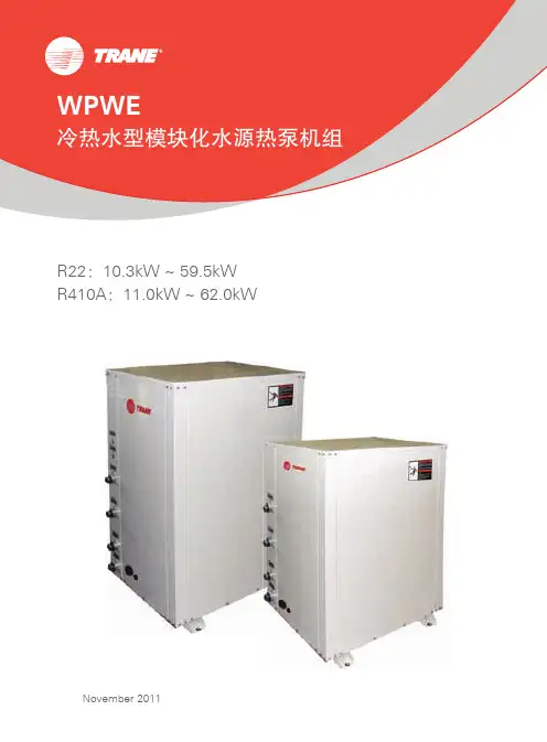
WPWE冷热水型模块化水源热泵机组R22:10.3kW ~ 59.5kWR410A:11.0kW ~ 62.0kWNovember 2011水环式系统地下水式系统地下环路式系统3.4.系统介绍与集中式空调系统相比,水源热泵系统一大优势在于在部分负荷时只需启动机组本身和循环水,不用频繁启停锅炉和冷却塔系统,这样大大节省了能源消耗;而在过渡季节,空调系统中各机组同时供冷和供暖的情况下,节能效果更加明显。
与水-风型水源热泵机组相比,水-水热泵在工程应用中具有以下的优点,建议业主或设计单位从实际需要出发,对不同的空调区域采用最为合适的机组形式:1.2.水温波动范围小,保证机组运行高效可靠,更可避免风冷机组冬季除霜的问题;各机组之间运行相对独立,个别机组的故障不会影响整个系统和其它机组的正常运行。
单户单表,每个用户可将自身的电表系统和空调系统连接,单独计费。
大楼管理人员、物业部门、业主再也无须为空调费用的结算发愁,真正实现公正与公平。
无需设立专门的锅炉房、冷冻机房和大型的通风管道,因此安装和投资费用大大减少。
两管制系统实现四管制系统功能,可同时满足各区域单独制冷/制热需求。
节约初投资高效节能可靠性高单独计费应用灵活室内侧采用传统的风机盘管形式,便于控制噪音、保证层高;减少机组数量,简化冷却水系统设计,易于达到水力平衡,减少水泵设计负荷,便于进行维护保养。
对于室内末端数量众多的场合,优势尤其明显;在室内侧可以用传统方式加载新风机组,运行性能稳定、可靠;针对住宅等使用场所,可以适当考虑各个房间的同时使用系数,合理减小主机的容量配置,进一步节省能源和初投资。
机组特性水冷式设计,采用高效涡旋式压缩机,能效比高;部分型号为双压缩机机组,可以实现逐级卸载,部分负荷效率更高;热力膨胀阀精确控制制冷剂流量,运行更稳定,应用范围更宽广。
机组针对水环、地下水及地下环路系统等多种应用进行不同调校,保证在不同工况条件下机组的正常运行。
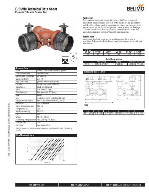
Close-off pressures are variable and actuator dependent, consult Select Pro and/or Price Guide for specifics.ApplicationThese valves are designed to meet the needs of HVAC and commercial applications requiring bubble tight shut-off for liquids. Typical applications include chiller isolation, cooling tower isolation, change-over systems, large air handler coil control, bypass and process control applications. The large Cv values provide for an economical control valve solution for larger flow applications. Designed for use in Victaulic® piping systems.Jobsite NoteValve assembly should be stored in a weather protected area prior toinstallation. Reference the butterfly valve installation instruction for additional information.2GKA B C D E F 19.1” [485]13.0” [330]12.7” [322]10.6” [269]9.7” [246]3.8” [97]F765VIC Technical Data SheetPressure Enhanced Rubber SeatD a t e c r e a t e d , 02/27/2020 - S u b j e c t t o c h a n g e . © B e l i m o A i r c o n t r o l s (U S A ), I n c .2GMA B C D E F 17.3” [440]13.0” [330]12.7” [322]10.6” [269]9.7” [246]3.8” [97]PKA B C D E F 15.5” [394]13.0” [330]16.5” [419]14.4” [366]9.7” [246]3.8” [97]Dimensions (Inches [mm])GMA B C D E F 14.1” [358]13.0” [330]12.7” [322]10.6” [269]9.7” [246]3.8” [97]Dimensions (Inches [mm])PRB(X)A B C D E F 15.5” [394]13.0” [330]14.0” [356]11.9” [302]9.7” [246]3.8” [97]Dimensions (Inches [mm])GM N4A B C D E F 15.8” [401]13.0” [330]15.3” [389]13.1” [334]9.7” [246]3.8” [97]F765VIC Technical Data SheetPressure Enhanced Rubber SeatD a t e c r e a t e d , 02/27/2020 - S u b j e c t t o c h a n g e . © B e l i m o A i r c o n t r o l s (U S A ), I n c .†Rated Impulse Voltage 800V, Type of action 1.AA, Control Pollution Degree 32*GKX24-MFT-X1 Technical Data SheetModulating, Electronic Fail-Safe, 24 V, for DC 2...10 V or 4...20 mA Control SignalD a t e c r e a t e d , 12/20/2019 - S u b j e c t t o c h a n g e . © B e l i m o A i r c o n t r o l s (U S A ), I n c .AActuators with appliance cables are numbered.Provide overload protection and disconnect as required.Actuators may also be powered by 24 VDC.Only connect common to negative (-) leg of control circuits.A 500 Ω resistor (ZG-R01) converts the 4 to 20 mA control signal to 2to 10 VDC.Control signal may be pulsed from either the Hot (Source) or Common(Sink) 24 VAC line.For triac sink the Common connection from the actuator must be connected to the Hot connection of the controller. Position feedback cannot be used with a triac sink controller; the actuator internalcommon reference is not compatible.IN4004 or IN4007 diode. (IN4007 supplied, Belimo part number 40155).46Actuators may be controlled in parallel. Current draw and input impedance must be observed.47Master-Slave wiring required for piggy-back applications. Feedbackfrom Master to control input(s) of Slave(s).Meets cULus requirements without the need of an electrical ground connection.!WARNING! LIVE ELECTRICAL COMPONENTS!During installation, testing, servicing and troubleshooting of this product, it may be necessary to work with live electrical components. Have a qualified licensed electrician or other individual who has been properly trained in handling live electrical components perform these tasks. Failure to follow all electrical safety precautions when exposed to live electrical components could result in death or serious injury.2*GKX24-MFT-X1 Technical Data SheetModulating, Electronic Fail-Safe, 24 V, for DC 2...10 V or 4...20 mA Control SignalD a t e c r e a t e d , 12/20/2019 - S u b j e c t t o c h a n g e . © B e l i m o A i r c o n t r o l s (U S A ), I n c .2*GKX24-MFT-X1 Technical Data SheetModulating, Electronic Fail-Safe, 24 V, for DC 2...10 V or 4...20 mA Control SignalD a t e c r e a t e d , 12/20/2019 - S u b j e c t t o c h a n g e . © B e l i m o A i r c o n t r o l s (U S A ), I n c .。
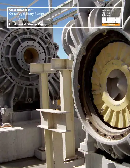
WARMAN®Centrifugal Slurry PumpsHorizontal Slurry PumpsSpecialists in delivering and supporting slurry and dewatering equipment solutions for global mining and mineral processing, the power sector, and general industry.Weir Minerals DivisionWeir Minerals is a world leader in the design andmanufacture of pumps, mill liners, hydrocyclones,slurry valves, screens, and rubber products for themining and minerals processing, dewatering, sulfurchemical and general industries. Based on advanced,and often patented, materials and designs, ourproducts are designed to add value to virtually anyaggressive, corrosive process.Superior wear life, low cost of operationIn slurry pumping, processing and control applications- where the cost of ownership often outweighscapital cost as a priority - we help our customersaddress issues such as longevity, capacity, efficiency ofoperation, and maintenance.Product strength lies in the superiority of our advancedhydraulic designs and our high performing wear andcorrosion resistant materials. Our leading research andmaterials scientists, plus our state of the art materialproduction facilities, support our world class productsand materials with a focus on superior wear life andlow cost of operation.Weir Minerals North AmericaLocated in Madison WI, Weir Minerals North Americais one of the many Weir Minerals facilities aroundthe world. These facilities include foundries, rubbermolding shops, and machining centers.1:A state-of-the-art hydraulic test laboratory is located in Madison, Wisconsin2:A Warman® 600 HTP pump being prepared for hydraulic testing. The massive rib reinforced casing and 102,000 lb (46,260 kg) bare weight illustrate the robust design and inherent safety of this 580 psi(4,000 kPa) rated pump 1: World class manufacturing facilities are part of Weir Minerals on six continents of the world2: A 20 ton fixture enables Weir Minerals to produce the largest slurry pumps in the world2New 4-vane Warman® WRT® impeller and matching throatbush is designed to improve wear performance, and assist our customers in reducing total ownership cost12Warman® horizontal slurry pump models include adiverse range of designs for the toughest duties.Warman® pumps deliver exceptional performanceThe Warman® horizontal slurry pump range is one of the world’s mostcomprehensive range of centrifugal slurry pumps for use in mining, chemical andindustrial applications. These horizontal slurry pumps are designed for ultra heavyduty applications such as mill discharge, process plant and tailings, high pressurepipelines, as well as other specialty applications.Typical applications and Warman® pump models most suitable for theseapplications are shown below. For special applications not listed, contact WeirMinerals North America or your local Weir Minerals representative. Since particlesize, concentration and abrasivity may affect your final selection, please consultWeir Minerals for final pump selection.Warman® AHP pumpWarman® horizontal pump models3servicesThe Warman® AH® pump is the world’s standard for the most difficult mill duties.A wide variety of impellers and shaft seals provide a perfect fit for a wide range of applications. The AH® pump provides excellent wear life while maintaining efficiency during the wear cycle, resulting in low total operating costs. The AH® pump, together with the Warman® MC™ pump series, provides a complete selection for most duties in the mill. From cyclone feed to regrind, flotation and tailings, the AH® pump is the best choice.4•Heavy duty construction with through-boltdesign provides ease of maintenance and minimaldowntime•Ductile iron fully lined casing provides durability,strength, safety, and long service life•Large diameter, slow turning, high efficiencyimpellers designed to achieve maximum wear lifeand low operating costs•Large, open internal passages designed to reduceinternal velocities, maximize wear life and loweroperating costs•Thick elastomer or alloy bolt-in liners providesuperior corrosion resistance plus offer ease of linerchange-out and interchangeability to reduce overallmaintenance costs and maximize wear life•Minimal shaft/impeller overhang reduces shaftdeflection and increases packing life•Cartridge-style bearing assembly allows formaintenance in a clean environment withoutremoval of the pump, resulting in reliable operationand prolonged bearing life•Grease or oil lubrication bearing assembly optionsoffer ease of maintenance and reduced downtime•Optional dry running shaft seal reduces or eliminatesflush water requirements•Effective expeller prolongs packing life whilereducing or eliminating flush water requirement Warman® AH®Warman® WRT®The new Warman® WRT®throatbush and impellercombination is a superiorupgrade for your existing pump,and is designed to enhanceefficiency and improve wearperformance5servicesThe Warman ® WBH ® slurry pump range offers more than 20 enhancements to the already state-of-the-art Warman ® AH ® slurry pumping technology, including a fully adjustable and rotatable throatbush to more evenly spread the wear and maintain the pump in tip-top performance for longer periods.Boasting a revolutionary one-piece frame for correct alignment of bearings, seal and impeller to front liner; as well as easier access for impeller adjustments, the WBH ® pump was built with enhanced efficiency and operational savings in mind.• One-point adjustment allows for adjusting the throatbush both rotationally and axially while the pump is in operation, overcoming localized wear• One-piece bearing frame design ensures correctalignment of bearings, seal and impeller • New hydraulics were shown to increase efficiency and lower energy consumption by up to 12% in the pump trials at CSA, Australia, compared with Warman ® AH ® pump in same duty • Large diameter expeller seals against high intake pressures without the need for gland seal water • Quick and easy impeller gap adjustments to maximize performance without shutdown • Fully lined design minimizes the risk of catastrophic failure with safety features including standard leak detection, optional vibration, temperature and wear monitoring, and the ability to add pressure relief and thermal cut-out devices • Warman ® Wear Reduction Technology (WRT ®) throatbush and four-vane impeller design with vanelets for extended wear life and reduced NPSH requirements • Large diameter shaft with short overhang combined with a robust and rigid one-piece bearing frame keeps the bearings aligned, which minimizes shaft deflection and vibration, as well as distortion from external piping loads • The one-piece bearing frame ensures goodcomponent alignment and concentricity through the seal area to reduce wear and extend seal lifeWarman ® WBH ®Warman ® WRT ®The new Warman ® WRT ® throatbush and impeller combination is a superiorupgrade for your existing pump and is designed to enhance efficiency and improve wear performanceWarman® MCR™/MC™ Metal/MCU™Severe duty lined pump designed for the most aggressive applications, such as mill circuitThe Warman® MC™ pump series is for the most aggressive wear applications. The Warman® MC™ pump easily manages large size particles in dense abrasive slurries and offers the right combination of ruggedness, durability, hydraulics and materials. From the most difficult mill discharge to water flushed crusher, the Warman® MC™pump series is the best choice.When paired with the Warman® AH® pump, virtually all the duties in your mill can be satisfied.•Ductile iron fully lined casing provides durability,strength, safety, and long service life•Large diameter, slow turning, high efficiencyimpellers designed to achieve maximum wear lifeand low operating costs•Large, open internal passages designed to reduceinternal velocities, maximize wear life and loweroperating costs•Unique, easily centered stuffing box reduces glandseal maintenance and extends packing life•Adjustable side liner maintains efficiency andextends service life (adjustable while running)•Quick wet end exchange minimizes downtime•Thick elastomer liners with alloy impellers providesuperior wear life on the most difficult cyclone feedand screen feed services•Interchangeable elastomer and alloy bolt-inliner offer ease of liner change-out and reducedmaintenance costs•Heavy duty construction with through-boltdesign provides ease of maintenance and minimaldowntime•Minimal shaft/impeller overhang reduces shaftdeflection and increases packing life•Cartridge-style bearing assembly allows formaintenance in a clean environment withoutremoval of the pump, resulting in reliable operationand prolonged bearing life•Separate fully removable suction cover on Warman®400 MCR™ pump facilitates access and replacementof the impeller, throatbush, and shaft sleeve withoutdisturbing coverplate or discharge piping•Left or right hand operation availableWarman® MCR™/MC™ Metal/MCU™WARMAN®Centrifugal Slurry Pumps6Warman® HTPFully lined pump for severe multi-stage applications which offers numerous ease of maintenance featuresThe Warman® HTP pump range represents the highest pressure-rated, large, lined pumps available from Weir Minerals with priority given to increased safety, wear life, and reliability.The Warman® HTP pump is rapidly establishing itself as the dominant pump in the Canadian oil sands, providing an efficient and durable solution to long distance hydro-transport and tailings duties.•Specifically designed hydraulics emphasize solidpassing capability, head generation, wear life,and efficiency to deliver overall outstandingperformance•Multi-stage high pressure operation to 580 psi•Major components designed with lifting pointslocated with respect to center of gravity andspecialized lifting tools enable rapid pumpmaintenance and turnarounds•Ductile iron fully lined casing provides durability,strength, safety, and long service life•Separate fully removable suction cover facilitatesaccess and replacement of impeller, throatbush,and shaft sleeve without disturbing coverplate ordischarge piping•Unique, easily centered stuffing box reduces glandseal maintenance and extends packing life•Grease or oil lubrication bearing assembly optionsoffer ease of maintenance and reduced downtime•Cartridge-style bearing assembly allows formaintenance in a clean environment withoutremoval of the pump, resulting in reliable operationand prolonged bearing life•Liner design reduces operating costs by allowingreplacement of individual components•Erosion and corrosion resistant elastomers or alloysare available to handle solids-laden and/or corrosiveslurriesWarman® HTP7 WARMAN®Centrifugal Slurry Pumps8Warman ® AHP/AHPPFully lined high pressure pump for multi-stage applicationsBased upon the popular Warman ® AH ® series pump, the Warman ® AHP/AHPPseries high pressure pump offers the same features and benefits as the AH ® pump, including identical hydraulics at up to 1000 psi.The high pressure capability allows the user to operate several pumps in series all consolidated into one pump house, saving the expense of supporting systems like gland water supply systems in an alternative design of several pump houses along the transport line.• Multi-stage high pressure operation to 1000 psi • Heavy duty construction with through-boltdesign provides ease of maintenance and minimal downtime• Ductile iron fully lined casing provides durability, strength, safety, and long service life • Large diameter, slow turning, high efficiencyimpellers designed to achieve maximum wear life and low operating costs • Large, open internal passages reduce internalvelocities, maximize wear life and lower operating costs • Thick elastomer or alloy bolt-in liners providesuperior corrosion resistance plus offer ease of liner change-out and interchangeability to reduce overall maintenance costs and maximize wear life • Minimal shaft/impeller overhang reduces shaft deflection and increases packing life • Grease or oil lubricated bearing options offer ease of maintenance and reduced downtime • Cartridge-style bearing assembly allows for maintenance in a clean environment withoutremoval of the pump, resulting in reliable operation and prolonged bearing lifeWarman ® AHPWARMAN ®Centrifugal Slurry PumpsWarman ® XUHeavy duty slurry pumpThe Warman ® XU pump range is Weir Mineral’s most recently released all metalunlined pump range that integrates newly designed wet end wear components with the long proven Warman ® mechanical end. Casing, impeller and liner have been optimized to provide low wear while delivering outstanding efficiency over a wide range of medium to heavy slurry applications such as coal, sand and gravel. With many unique features, the Warman ® XU pump is easy to maintain and is designed to offer the lowest cost of ownership in its class.Warman ® XU9• Configured volute casing distributes material at point of maximum wear to extend life when pumping large solids• Low V cutwater design reduces slurry velocities and wear in the casing, allowing operation over a wide range of flows • Five-vane, thick sectioned, high efficiency impellers offer maximum wear life and low operating costs • Patented impeller wear ring profile reduces wear on impeller and throatbush area by restricting recirculation • Unique “tear drop” shaped frame plate liner insert insures any localized side wall wear occurs on liner and not on casing • Wet end components constructed from abrasion resistant solid chrome iron, providing excellent wear life in most slurry applications • Multiple shaft sealing configurations are available to best suit application requirements and are easily converted from one to another without expensive mechanical end changes • Compact cartridge-style bearing assemblies offer reduced shaft/impeller overhang and minimize shaft deflection resulting in increased packing life and the ability to accept a range of mechanical seals • Exceptional dry gland sealing performance due to improved expeller/impeller ratios reduces flush water requirements and lowers operating costs • Full and low flush gland sealing options allow precise matching of seal water consumption to application needs • Grease or oil lubrication bearing assembly options offer ease of maintenance and reduced downtime • Quick release clamping collar design facilitates impeller removal • Hydraulically interchangeable with long proven Warman ® AH ® pump designsWARMAN ®Centrifugal Slurry PumpsWarman® AHF/LF/MFHeavy duty froth pump for tough flotation froth duties Designed to handle heavy froth, the Warman® horizontal froth pump has a unique inlet and impeller design that is very successful where others fail.A large oversized inlet with a unique impeller inducer blade handles heavy froth and higher viscosity dense slurries with ease. The Warman® AHF/LF/MF line of horizontal froth pumps has proven valuable for very dense slurries where viscosity starts to become a pumping issue for the standard slurry pump.10•Heavy duty construction with through-boltdesign provides ease of maintenance and minimaldowntime•Ductile iron fully lined casing provides durability,strength, safety, and long service life•Large diameter, slow turning, high efficiencyimpellers designed to achieve maximum wear lifeand low operating costs•Large, open internal passages designed to reduceinternal velocities, maximize wear life and loweroperating costs•Unique impeller design for most difficult frothapplications•Thick elastomer or alloy bolt-in liners providesuperior corrosion resistance plus offer ease of linerchange-out and interchangeability to reduce overallmaintenance costs and maximize wear life•Minimal shaft/impeller overhang reduces shaftdeflection and increases packing life•Cartridge-style bearing assembly allows formaintenance in a clean environment withoutremoval of the pump, resulting in reliable operationand prolonged bearing life•Standard Warman® AH® pump and Warman® Lpump can be converted by replacing cover plate,throatbush and impeller•Full flush, low flow or dry running centrifugal sealsminimize water usage and operating costsWarman® AHF/LF/MF*Lower light blue areas: recommended maximum operating range on aerated slurriesWARMAN®Centrifugal Slurry PumpsWarman ® Series 1000General purpose slurry pumpThe Warman® Series 1000 pump is a long proven horizontal end suction centrifugalpump that will reliably and economically handle abrasive and corrosive medium duty services.Several unique features make the Series 1000 pump ideal for handling stringy/fibrous slurries, low NPSHA applications and services that require minimum dilution due to gland seal water.• Heavy duty construction with through-bolt casing design provides ease of maintenance and minimal downtime • Erosion and corrosion resistant elastomers or metal alloy liners are available to handle solids-laden and/or corrosive slurries • Semi-open impeller easily passes large or stringy particles and is well suited for froth-laden slurries • Unique impeller hydraulic design allows operation in systems with low NPSHA • Cartridge-style bearing assemblies offer a compact reliable design that reduces shaft/impeller overhang, decreasing deflection for improved packing life and allows for easy rebuilds • Multiple shaft sealing configurations are available to best suit application requirements including standard wet and dry glands as well as mechanical seals • Effective expeller prolongs packing life while reducing or eliminating flush water requirement • Casing drain plug allows for component wearinspection as well as draining slurry from the pump to prevent freezing or corrosion after flushing • Grease or oil lubricated bearing assemblies offer ease of maintenance and reduce downtime11Warman ® Series 1000WARMAN ®Centrifugal Slurry PumpsWarman® HH/H/HRMHeavy duty high head lined slurry pumpThe Warman® HH/H/HRM pump lines were designed to produce high heads per stage at high pressures.Commonly used for long distance transport lines, the Warman® HH/H/HRM pump lines can often satisfy application duties with a single pump where others require multiple pumps in series.12•Ductile iron fully lined casing provides durability,strength and long service life•Multi-stage high pressure operation to 750 psi(Warman® H pump to 1000 psi)•Heavy duty construction with through-boltdesign provides ease of maintenance and minimaldowntime•Large diameter, slow turning, high efficiencyimpellers designed to achieve maximum wear lifeand low operating costs•Large, open internal passages designed to maximizewear life and lower operating costs•Thick elastomer and alloy liners provide superiorcorrosion resistance and maximum wear life•Full flush gland, low flow, and dry runningcentrifugal seals reduce flush water usageminimizing pump operating costsWarman® HH/HRMWARMAN®Centrifugal Slurry PumpsWarman ® LRugged heavy duty slurry pump for medium to lower headsThe Warman ® L series pumps incorporate the same design points as the Warman ® AH ® pump plus higher efficiency impellers at an attractive initial cost.Designed for rugged duties while offering higher efficiencies, the Warman ® L series is a combination of the proven Warman ® AH ® pump’s unique features. The Warman ® L series provides the widest range of hydraulics from the 3/4” to a 26” discharge pumps. The 3/4” is perfect for the laboratory or in demonstration plants.• Heavy duty construction with through-boltdesign provides ease of maintenance and minimal downtime • Ductile iron fully lined casing provides durability, strength, safety, and long service life • Large diameter, slow turning, high efficiencyimpellers designed to achieve maximum wear life and low operating costs • Large, open internal passages designed to reduce internal velocities, maximize wear life and lower operating costs • Thick elastomer or alloy bolt-in liners providesuperior corrosion resistance plus offer ease of liner change-out and interchangeability to reduce overall maintenance costs and maximize wear life • Designed for rugged duties while offering excellent efficiencies • Minimal shaft/impeller overhang reduces shaft deflection and increases packing life • Cartridge-style bearing assembly allows for maintenance in a clean environment withoutremoval of the pump, resulting in reliable operation and prolonged bearing life • Grease or oil lubrication bearing assembly options offer ease of maintenance and reduced downtime • Full flush gland, low flow, and dry running centrifugal seals reduce flush water usage minimizing pump operating costs • Mechanical seals reduce flush water usage, minimizing pump operating costs13Warman ® LWARMAN ®Centrifugal Slurry PumpsWarman® GSLAbsorber recycle pumpSince the introduction of the first Flue Gas Desulfurization (FGD) systems in the 1970s, Weir Minerals has supplied more than 4,000 specially designed FGD pumps worldwide.Warman® GSL pumps have the highest efficiencies in the industry achievable throughout the life of the impeller.14Warman® GSL•Ductile iron fully lined casing provides durability,strength, safety, and long service life•Cartridge-style bearing assembly allows formaintenance in a clean environment withoutremoval of the pump, resulting in reliable operationand prolonged bearing life•High efficiency design minimizes energyconsumption and reduces operating costs•Liner design reduces operating costs by allowingreplacement of individual components•Back pull design affords easy maintenance•Mechanical seals reduce flush water usageminimizing pump operating costs• Warman® GSL pump design incorporates thelatest material development, hydraulic designimprovements and modern manufacturingmethods of the Warman® L pump WARMAN®Centrifugal Slurry PumpsNew Warman® GSL polymer castceramic components available.Contact your local Weir Minerals salesrepresentative for more information.®Warman ® WGR ®Medium duty slurry pumps for sand and aggregate applicationsThe streamlined design allows easy access to all parts of the pump and theinternal components, making servicing easier and reducing downtime. When this is combined with the long service life of our parts and the proven wear life of our proprietary Linatex ® premium rubber, Weir Minerals provides pumping solutions that are designed to achieve the lowest total cost of ownership in operation.Warman ®WGR ®pump - quick selection chart• Our new patented Warman ® WRT ® throatbush and impeller designs minimize turbulence and cavitation for extended wear life and maintenance performance • Impeller and gland assembly can be replaced through the suction side of the pump• Replaceable Linatex ® rubber liners provide superiorabrasion resistant performance in fine slurry applications • Patented flexible discharge adaptor is the same size as the inlet and positioned so the pump can be fully serviced without removing the discharge piping • Loose swivel flanges are offered to match mating pipe orientations • Adjustable impeller with release collar can beadjusted externally to achieve optimum clearance between the impeller and the throatbush for the full working life of the wear components • Newly designed larger impeller allows for lower speeds which results in longer wear life • Incorporation of the removable suction cover in the cover plate means that the throatbush can be replaced without incurring the cost of removal of the cover plate • New design gives increased durability, resulting in lower overall lifetime costsWarman ® WGR ®1001000 10000Flowrate ( usgpm )351008050250200150T o t a l h ea d (f e e t )US gallons per minute (gpm)0 20406080100120 14016010H e a d ( f t ) Warman ® WRT ®The new Warman ® WRT ®throatbush and impeller combination is a superiorupgrade for your existing pump, and is designed to enhance efficiency and improve wear performanceCubic meters per hour (m /hr)Total head (meters)15For further information on any of these products or our support services contact your nearest sales office or visit:WARMAN ® Centrifugal Slurry Pumps GEHO ® PD Slurry PumpsLINATEX ® Rubber Products VULCO ® Wear Resistant Linings CAVEX ® HydrocyclonesFLOWA Y ® PUMPS Vertical Turbine Pumps ISOGATE ® Slurry ValvesMULTIFLO ® Mine Dewatering Solutions HAZLETON ® Specialty Slurry PumpsLEWIS ® PUMPS Vertical Chemical Pumps WEIR MINERALS SERVICES™Copyright © 2008, 2012 Weir Slurry Group, Inc.. All rights reserved. WARMAN is a registered trademark of Weir Minerals Australia Ltd and Weir Group African IP Ltd; CAVEX, HAZLETON, AH, WRT, WBH, WGR and MULTIFLO are registered trademarks of Weir Minerals Australia Ltd; LEWIS and LEWIS PUMPS are registered trademarks of Envirotech Pumpsystems Inc; GEHO is a registered trademark of Weir Minerals Netherlands bv; FLOWAY is a registered trademark of Weir Floway Inc.; VULCO is a registered trademark of Vulco SA; ISOGATE is a registered trademark of Weir do Brasil Ltda.; LINATEX is a registered trademark of Linatex Ltd; SENTINEL is a registered trademark of Weir Slurry Group, Inc.; MC, MCR and MCU are trademarks of Weir Slurry Group, Inc.; WEIR is a registered trademark of Weir Engineering Services Ltd. Certain features of some of the products featured in this publication are protected worldwide by patents pending and registered.The Weir Minerals Services ™ Sentinel ® program is a team concept providing lower Measured Total Ownership Cost (MTOC) throughimproved reliability, lower power consumption and reduced maintenance cost.Our menu approach allows each customer to select the level of commitment and participation they feel best meets their needs.Weir Minerals Services ™ Sentinel ® Program Pump users enter into formal agreements with Weir Minerals with the aim of benefiting from ongoing reductions in operating costs.WEIR MINERALS SERVICES ™Weir Minerals Services ™ Sentinel ® Program modules include:• Cooperative cost focus groups • Pump audits• Equipment maintenance monitoring • Wear life monitoring• Performance based agreements • Spare parts supply agreements • Customized training programs • Equipment rebuild services • Pump exchange services •Tailored maintenance packages。
GE发电设备与水处理水处理及工艺过程处理ZeeWeed®1500超滤膜产品技术手册V2.0版1 公司简介2 ZeeWeed®超滤概述3 ZeeWeed®1500膜组件和系统3.1 膜组件3.2 系统操作说明和系统控制4 工艺过程说明4.1 预过滤4.2 产水4.3 反洗4.4 维护性清洗4.5 恢复性清洗4.6 膜完整性测试附件A 膜组件尺寸和容差附件B 典型工艺流程图附件C 典型PID图附件D ZeeWeed®1500膜堆和膜列示意图124 4 67 7 7 8 9 10 1112 13 14 15注意:本文件内容是GE水处理及工艺过程处理公司的专有和机密信息,而且本文件的版权由GE 水处理及工艺过程处理公司所有。
本文提供的信息仅供被授权而且履行保密义务的人员使用。
本手册的所有权和更新权归GE水处理及工艺过程处理公司的UF/MBR产品管理部。
本文件可能随时更新,因此应及时用最新发行版本更换所有旧版本。
旧版本中所包括的信息应视为无效信息。
在开始一项新的设计前,应通过合作方网站查询最新信息。
本文包括的信息是根据我们当前具备的知识编制的。
一个系统的设计和正确参数的选择最终由OEM合作方负责。
如果您需要进一步协助或澄清,请与GE 水处理及工艺过程处理公司工艺经理联系或登录GE水处理及工艺过程处理公司网站查询。
1.1 通用电气(GE)公司通用电气(GE )公司是一家全球领先的科技、服务和金融公司,是全球最大的多元化企业,致力于解决世界上最棘手的问题。
GE 的产品和服务范围广阔,从能源、石油天然气、发电、水处理、航空、医疗、运输系统、家电、照明,到金融,客户遍及全球100 多个国家,拥有30 多万员工。
杰夫·伊梅尔特先生是现任董事长及首席执行官。
GE公司的历史可追溯到托马斯·爱迪生,他于1878年创立了爱迪生电灯公司。
1892年,爱迪生通用电气公司和汤姆森-休斯顿电气公司合并,成立了通用电气公司(GE)。
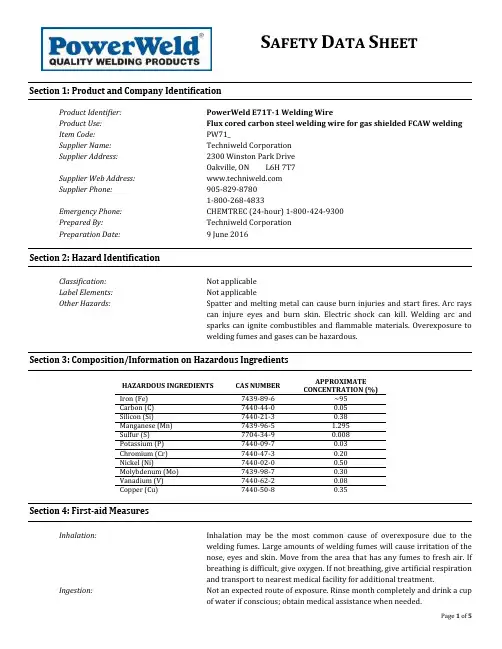
S AFETY D ATA S HEETSection 1: Product and Company IdentificationProduct Identifier:PowerWeld E71T-1 Welding WireProduct Use:Flux cored carbon steel welding wire for gas shielded FCAW welding Item Code:PW71_Supplier Name:Techniweld CorporationSupplier Address:2300 Winston Park DriveOakville, ON L6H 7T7Supplier Web Address:Supplier Phone: 905-829-87801-800-268-4833Emergency Phone:CHEMTREC (24-hour) 1-800-424-9300Prepared By:Techniweld CorporationPreparation Date:9 June 2016Section 2: Hazard IdentificationClassification:Not applicableLabel Elements: Not applicableOther Hazards: Spatter and melting metal can cause burn injuries and start fires. Arc rayscan injure eyes and burn skin. Electric shock can kill. Welding arc andsparks can ignite combustibles and flammable materials. Overexposure towelding fumes and gases can be hazardous.Section 3: Composition/Information on Hazardous IngredientsHAZARDOUS INGREDIENTS CAS NUMBERAPPROXIMATE CONCENTRATION (%)Iron (Fe) 7439-89-6 ~95Carbon (C) 7440-44-0 0.05Silicon (Si) 7440-21-3 0.38Manganese (Mn) 7439-96-5 1.295Sulfur (S) 7704-34-9 0.008Potassium (P) 7440-09-7 0.03Chromium (Cr) 7440-47-3 0.20Nickel (Ni) 7440-02-0 0.50Molybdenum (Mo) 7439-98-7 0.30Vanadium (V) 7440-62-2 0.08Copper (Cu) 7440-50-8 0.35Section 4: First-aid MeasuresInhalation:Inhalation may be the most common cause of overexposure due to thewelding fumes. Large amounts of welding fumes will cause irritation of thenose, eyes and skin. Move from the area that has any fumes to fresh air. Ifbreathing is difficult, give oxygen. If not breathing, give artificial respirationand transport to nearest medical facility for additional treatment.Ingestion:Not an expected route of exposure. Rinse month completely and drink a cupof water if conscious; obtain medical assistance when needed.Eye Contact:If arc flash or burns occur, obtain medical assistance. Large exposure towelding fumes may cause irritation to the eyes. Immediately flush upperand lower eyelids with plenty of water. After initial flushing, remove anycontact lenses and continue flushing for at least 15 minutes. Rest eyes for30 minutes. If redness, burning, blurred vision or swelling persists, visitnearest medical facility for additional treatment.Skin Contact:Large exposure to welding fumes may cause irritation to skin. If burnsoccur, flush with clean cool water for 15 minutes; obtain medical assistancewhen needed.Symptoms:Treat symptomatically; symptoms may be delayed. Show this SDS to theattending physician.NOTE: In all severe cases, contact physician immediately. Local telephone operators can provide number of regional poison control centre.Section 5: Fire-fighting MeasuresFlammable:Not flammable; emits toxic fumes when heatedMeans of Extinction:Use extinguishing method most appropriate for surrounding fire (waterspray, alcohol-resistant foam, dry chemical or carbon dioxide); do not usewater on molten metal. Large fires may be flooded with water from adistance.Auto-ignition Temperature:Not availableExplosion Data Sensitivity toMechanical Impact:Not availableExplosion Data Sensitivity toStatic Discharge: Not availableSpecial Equipment:See belowPrecautions for Fire Fighters:In the event of fire, wear self-contained breathing apparatus and fullprotective gear.Section 6: Accidental Release MeasuresProtective Equipment:See Section 8Emergency Procedures:This product is in rod form and has no hazards as shipped.Leak or Spill Procedure:If spilled, the product may be picked up and placed back into the container.If metals become molten, contain with sand and allow to return back into asolid for recycle as scrap.Section 7: Handling and StorageHandling Procedures and Equipment:Avoid contact with eyes. Avoid breathing dust. Avoid prolonged or repeatedcontact with skin. Keep container closed. Use only with adequateventilation. Wash thoroughly after handling. Avoid contact of spilledmaterial and runoff with soil and surface waterways.Storage Requirements:Store in a cool, dry and low humid location. Keep away from heat and openflame.Incompatibilities:Strong acids and bases, antioxidants and halogens.Section 8: Exposure Controls/Personal ProtectionExposure Limits:HAZARDOUS INGREDIENTS CAS NUMBER OSHA PEL (mg/m3) ACGIH TLV (mg/m3)Iron (Fe) [as oxide fume) 7439-89-6 10 5(resp)Carbon (C) 7440-44-0 10, 2(resp) 15, 5(resp)Silicon (Si) 7440-21-3 15(dust), 5(resp) -Manganese (Mn) [as fume] 7439-96-5 5 0.2(resp), 0.1(inhal)Sulfur (S) 7704-34-9 - -Potassium (P) [as oxide fume] 1312-76-1 10, 5(resp) 15(dust), 5(resp)Chromium (Cr) 7440-47-3 1 0.5Nickel (Ni) 7440-02-0 1 1.5(inhal)Molybdenum (Mo) 7439-98-7 15(dust), 5 10(inhal), 3(resp)Vanadium (V) [as oxide fume] 7440-62-2 0.05(dust) 0.5(dust)Copper (Cu) 7440-50-8 1(dust), 0.1(fume) 1(dust), 0.2(fume) Engineering Controls:Ensure proper ventilation and respiratory protection is used when welding,brazing or processing. Respiratory protection is recommended andinformation may be found regarding the OSHA STANDARDS (29 CRF1910.134), as well as CSA Standards Z94.4, along with many other safetystandards.Personal Protective Equipment:Respiratory: Use NIOSH approved respirator if exposure limits areexceeded or where dust exposures are excessive. Consider the potential forexposure to components of the coatings or base material being ground inselecting proper respiratory protection. Refer to OSHA’s specific standardsfor where appropriate. Selection of respiratory protection depends on thecontaminant type, form and concentration. Select and use respirators inaccordance with OSHA 1910.134 and good industrial hygiene practice.Hands: Cloth or leather gloves are recommended.Eyes: Wear helmet or face shield with filter lens of appropriate shadenumber. See ANSI/ASC Z49.1 Section 4.2. Provide protective screens andflash goggles, if necessary, to shield others.Skin: Approved protection (ie./ welders gloves, apron, sleeves, jacket, etc.)should be worn to prevent injury from sparks and contamination ofclothing.Section 9: Physical and Chemical PropertiesPhysical State:SolidOdour and Appearance:Odourless metal wireOdour Threshold (ppm): Not availablepH: Not availableMelting Point:Not availableFreezing Point: Not availableBoiling Point:Not availableFlashpoint:Not availableUpper Flammable Limit (% by volume):Not availableLower Flammable Limit (% by volume):Not availableSection 10: Stability and ReactivityChemical Stability:Stable under normal conditionsPossible Hazardous Reactions:Not availableConditions to Avoid:None knownMaterials to Avoid (Incompatibilities):Acids and strong oxidizersConditions of Reactivity:See aboveHazardous Decomposition By-Products: Welding fumes and gases cannot be classified simply. The composition andquantity of both are dependent upon the metal being welded, the process,procedure and welding consumables used. Other conditions which alsoinfluence the composition and quantity of the fumes and gases to whichworkers may be exposed include: coating on the metal being welded (i.e.paint, painting, galvanizing), the number of welders, the size of the workarea, the quality and the amount of ventilation, the position of the weldershead with respect to the fume plume, as well as the presence ofcontaminants in the atmosphere (such as chlorinated hydrocarbon vaporsfrom the cleaning and degreasing activities).When an electrode is consumed, the fume and gas decomposition productsgenerated are different in percent and form from the ingredients listed inSection 3. Fume and gas decomposition, and not the ingredients in theelectrode, are important. The concentration of a given fume or gascomponent may decrease or increase by many times the originalconcentration. Also, new compounds not in the electrodes may form.Decomposition products of normal operation include those originatingfrom the volatilization, reaction or oxidation of the materials shown inSection 3, plus those from the base metal coating, etc., as noted above.Reasonable expected fume constituents of this product would include:Complex oxides of iron, manganese, silicon, chromium, nickel, molybdenum,copper, carbon dioxide, carbon monoxide, ozone and nitrogen oxides.Present OSHA exposure limit for hexavalent chromium, nickel and ormanganese may be reached before limit of 5 mg/m3of general weldingfumes is reached.Gaseous reaction products may include carbon monoxide and carbondioxide, ozone and nitrogen oxides may be formed by the radiation from thearc in addition to shielding gas like argon and helium when employed.Determine the composition and quantity of fumes and gases to whichworkers are exposed by taking an air sample from inside the welder’shelmet if worn or in the worker’s breathing zone. Improve ventilation ifexposures are not below limits.See ANSI/AWS F1.1, F1.3 and F1.5, available from the American Welding Society, 550 N.W.LeJeune Road, Miami, FL 33126. See AWS publications: “Fumes & gases in the weldingenvironment” & “Effects of welding on health”Hazardous Polymerization:Not applicableSection 11: Toxicological InformationSkin Contact:Arc rays can burn skin; skin cancer has been reported.Skin Absorption: Not applicableEye Contact:Arc rays can injure eyes.Inhalation:Inhalation is the most likely route of exposure; refer to “Effects of AcuteExposure” and “Effects of Chronic Exposure” below.Ingestion:Unlikely due to form of product.Effects of Acute Exposure:Overexposure or inhalation of large amounts of welding fumes may causesymptoms such as metal fume fever, dizziness, nausea, dryness andirritation of your nose, throat or eyes as well as lung disease.Effects of Chronic Exposure:Overexposure or prolonged inhalation of large amounts of welding fumessymptoms may include damage to the central nervous system, respiratorysystem, skin and could affect organs such as pancreas and liver.Irritancy of Product:Not availableSensitization to Product:This product is not expected to cause skin sensitization.Carcinogenicity:Nickel and Chromium, and their compounds, are on the list of InternationalAgency for Research on Cancer as CarcinogenicReproductive Effects:Not availableRespiratory Sensitization:Not availableToxicological Data:Not availableSection 12: Ecological InformationAquatic and Terrestrial Toxicity:Dust created from this product is harmful to the environmentPersistence and Degradability:Information not availableBio accumulative Potential:Information not availableSoil Mobility:Information not availableSection 13: Disposal ConsiderationsNOTE: Always dispose of waste in accordance with local, provincial and federal regulations.Safe Handling:Gloves can be worn while handling discarded or unwanted product.Methods of Disposal:For product elimination, consult recycling companies or appropriate localauthority. This product is not considered hazardous waste if discarded.Residue from welding consumables and processes could degrade andaccumulate in soils and groundwater.Section 14: Transportation InformationThis material is not considered as a dangerous good per transportation regulations.Section 15: Regulatory InformationCanadian Controlled ProductsRegulations:This product has been classified according to the hazard criteria of the CPR,Section 33, and this SDS contains all required information.U.S. California Proposition 65:This product contains a chemical(s) known to the State of California tocause cancer and/or birth defects or other reproductive harm.California Proposition 65 Carcinogens& Reproductive Toxicity (CRT):Hexavalent chromium compounds, NickelU.S. State Right to Know/ HazardousSubstance Lists (various): The following components are listed on various U.S. State substance lists:Nickel, Chromium, Copper, Manganese, Molybdenum, Silicon, HexavalentchromiumSection 16: Other InformationPreparation Date:9 June 2016Date of Last Revision:9 June 2016This SDS format is in accordance with GHS. Techniweld Corporation provides the information contained herein in good faith but makes no representation as to its comprehensiveness or accuracy. This document is intended only as a guide to the appropriate precautionary handling of the material by a properly trained person using this product. Product use and conditions of use are beyond the control of Techniweld. Warranty of materials is limited to test results of product performance as detailed in certificates of compliance. Interpretation of test results is the responsibility of end-user. No other warranties, expressed or implied, are made.。
硅酸铝纤维毡技术规格硅酸铝纤维毡是一种常用于高温绝热领域的材料,具有优异的隔热性能和耐火性能。
它由硅酸铝纤维制成,经过特殊工艺形成连续纤维网状结构,具有轻质、柔软的特点。
它在工业领域广泛应用,如石化、冶金、电力等行业。
1. 硅酸铝纤维毡的特性硅酸铝纤维毡具有以下主要特性:1.1 高温隔热性能:硅酸铝纤维毡作为隔热材料,具有极低的热传导系数,能够有效减少能量的传递,提供良好的隔热效果。
1.2 轻质柔软:硅酸铝纤维毡具有轻质和柔软的特点,使其易于安装和加工,适用于复杂形状和曲面的绝热需求。
1.3 耐高温性能:硅酸铝纤维毡能够耐受高达1400摄氏度的高温环境,不会发生融化、变形等现象,确保设备的安全运行。
1.4 耐腐蚀性能:硅酸铝纤维毡对一些酸、碱等腐蚀性介质具有较好的耐受性,能够保持长时间的稳定使用。
2. 硅酸铝纤维毡的技术规格2.1 密度:硅酸铝纤维毡的密度通常在100-200kg/m³之间,不同的应用领域和要求可根据实际需要进行调整。
2.2 厚度:硅酸铝纤维毡的厚度一般在10-50mm之间,具体厚度根据实际隔热要求和应用环境而定。
2.3 尺寸:硅酸铝纤维毡的常见尺寸为600m m × 400mm,也可根据需要进行定制。
2.4 火焰传播性:硅酸铝纤维毡一般具有良好的阻燃性能,在高温下不易引燃,且不会传播火焰。
2.5 热导率:硅酸铝纤维毡的热导率通常在0.03-0.06W/(m·K)之间,具有较好的隔热效果。
3. 硅酸铝纤维毡的应用领域硅酸铝纤维毡广泛应用于工业领域,包括但不限于以下几个方面:3.1 石化行业:硅酸铝纤维毡可用于炉膛测温、炉墙、管道和设备的隔热,有效降低能源损耗,提高生产效率。
3.2 冶金行业:硅酸铝纤维毡可应用于冶炼炉、转炉、高炉等设备的隔热,有效保护设备,提高冶金工艺的稳定性。
3.3 电力行业:硅酸铝纤维毡可用于发电厂的锅炉、电机绝缘材料等,具有良好的断热性能和耐高温性能。

Laborbericht 实验报告Lackabblaetterung 油漆剥落Lackablaufbehälter 油漆排放槽Lackabplatzung 漆膜剥落; 龟裂Lackblech 油漆样板Lackeinschluss 油漆夹杂物,灰粒Lackhobel 油漆刨刀Lackiererei 油漆车间Lackindifferenz 对油漆惰性Lackkoaguliermittel 漆雾凝聚剂Lackkoagulierung 油漆凝胶Lackkonservierer 油漆防护蜡Lackläufer 油漆流挂Lacklaeufer 油漆流痕; 油漆涕痕Lacknase 漆瘤Lacknebel 漆雾; 油漆点子Lackoberflaechen - Audit 油漆表面奥地特Lackpflegemittel 油漆保护剂; 硬蜡Lackpickel 漆苞Lackstruktur 油漆结构Lackverlaufsstoerung 油漆操作不当Ladeautomat 自动装料机Ladedruckfuehler 增压压力传感器Ladefaehigkeit 载重量Ladeleitung 充电导线Ladeluftkuehlung 增压空气中冷laden 装载; 充电Laderaum 载物空间Ladungswechsel 换气Ladungswechselsystem 换气系统Ladungswechselverlust 换气损失Laenge nicht eingehalten 长度不符Laengen/Querschnittsverhaeltnis 长度和横截面比值Laengenausgleich 长度平衡Laengeneinheit 长度单位Laengerippe 纵向筋板Laengseinbau 纵置式结构Laengseinbau 纵向布置laengsgeteilt 纵向剖分Laengskraftschwankung 轴向力波动Laengsschlitteneinheit 纵向滑台Laengstraeger 纵梁板Laengstraeger 纵梁laeppen 研磨; 磨光Laeppmaschine 研磨机床Laerm 嘈杂声; 噪声Laerm mindern 降低噪音Laermschutz 噪声防护Laeufer 流挂(漆膜上油漆流淌的痕迹)Laeufer 流挂Lage der Nockenwelle 凸轮轴位置Lager 支承; 支座; 轴承; 支架; 仓库Lagerabgang 仓库发料Lagerbestand 库存量Lagerbestand 库存Lagerbock 轴承座Lagerbock 支承座Lagerbolzen 固定螺栓Lagerbuechse 轴套Lagerbuegel 支承夹Lagerfaehigkeit 仓储性能Lagerfreigabe 入库认可Lagergasse 轴瓦安装面lagerhaltig 库存有货的Lagerhaltung 仓储Lagerhaube (曲轴)轴承盖Lagerhuelse 轴套Lagernummer 库存编号Lagerplatte 支承板Lagerregler 位置控制器lagerrichtig 位置正确的Lagerschale 轴瓦Lagerschmieroel 轴承润滑油Lagersitz 轴承安装孔Lagersteg 曲轴轴承窄座Lagerstelle 轴颈; 支承部位Lagerteller 上弹簧垫Lagerungsbestaendigkeit 仓储性能Lagerungstelle 轴承位置Lagervermerk 仓库标记Lagervorrat 库存Lagerwirtschaft 物流经济Lagerzugang 仓库进料Lagetoleranz 位置公差Lambda-Regelparameter λ控制参数Lambda-Regelung 空燃比闭环控制Lambdasonde λ探测器Lambda-Sonde 氧传感器Lambda-Verschiebung λ偏移量Lamelle 滤片; 膜片; 片; 摩擦片Lamellenkupplung 摩擦片式离合器Laminarschale 涂膜壳体Laminat 层压板Lammellen 摩擦片Lampe "Schmierung Stoerung" 润滑故障显示灯Lampenanzeige 灯光指示Lampenfassung 灯座Lampentest 指示灯测试Langhobelmaschine 龙门刨langhubrig 长行程的Langloch 长孔Langlochstempel 冲长孔凸模Langzeitarbeitslosigkeit 长期失业Langzeitqualitaet 长期使用质量Langzeitschaden 长期使用后发生的损坏Langzeitvertrag 长期(采购)Lasche 连接板laschen 连接不到位Laserschweissen 激光焊Lastenaufzug 载货电梯Lastenheft 设计准则Lastenheft 技术说明书Lastenheft 设计任务书Lastenheft 产品手册(产品建议书)Lastenheftvorgabe 负荷要求Lastgruppenueberschneidung 负荷分档之间的重叠Lastspannung 电源Lastspiel 负载循环Lasttrum 有载段,拉紧段Lastverteileranlage 配电所配电装置Lastverteilstelle 动力配电装置Lastwechsel 负荷转换Lastwechsel 负荷变换Lastwechselschlag 负荷变化反应滞后Lattenverschlag 护墙板,板条Lauf 运转; 转动laufend 运转中的Laufflaechenverschleissanzeiger 胎面磨损标记Laufkran 桥式行车Laufqualitaet 传动质量Laufrad 滚轮Laufrolle 滑轮Laufruhe 运转安静(无噪音)Laufschiene 行车轨道Laufwerk 驱动器;走行机构Laufzeit 期限; 有效期Lautsprecherblende 扬声器盖板Leasing-Vertrag 租赁合同Lebensdauer 使用期; 寿命Lebensversicherung 人寿保险lebenswichtig 生命攸关的Leckage 泄漏; 漏损Leckanzeige 泄漏显示Leckoel 漏泄油Leerhub 空行程Leerlauf 怠速Leerlaufbrennstoffbedarf 怠速燃料消耗Leerlaufdrehzahl 怠速转速Leerlaufeinstellung 怠速调整Leerlauf-Fuellungs-Anhebung 怠速充量加浓器Leerlauffuellungsregelung 怠速充气控制Leerlauf-Fuellungs-Regelung 怠速充量调节器Leerlauffuellungsschrittmotor 怠速充量调节步进电机Leerlaufleistung 怠速功率Leerlaufqualitaet 怠速质量Leerlaufregelung 怠速控制Leerlaufregler 怠速调节器Leerlaufschalter 怠速开关Leerlaufstabilisierung 怠速稳定Leerlaufzuendeinstellung 怠速点火调整Leerstation 空工位Leersteckdose 空插座Leertrum 无载段,回行段Legierung 合金Lehnenlager 靠背支承Lehnenlager 扶手支座Lehnenrahmen 靠背骨架Lehrdorn 塞规Lehre 检具; 样架; 量架Lehre 量规Lehrenbau 检具制造Lehrenbohrmaschine 坐标镗床; 钻磨镗床Lehrenbohrwerk 坐标镗床Lehrenhaltigkeit 与样架的一致性Lehrenteam 检具小组Leichtanlauf 轻载启动leichtes Nutzfahrzeug 轻卡leichtgeoelt 涂少量机油的Leichtlauf 轻载行程Leichtlauf-Motorenoel 常规机油Leichtmetallrad 轻金属车轮Leiharbeit 外借劳力Leiste 条板Leiste 压条Leiste 镶条; 压板Leistenschraube 导向板螺丝Leistung 功率Leistungsaufnahme 消耗功率Leistungsbeschraenkung 工作能力受限Leistungsbeurteilung 工作鉴定Leistungsbewertung 工作评分Leistungsbremse 测功房Leistungsbremse 水力测功器Leistungsdichte 功率密度Leistungsentfaltung 功率扩大Leistungsforderung 功率要求Leistungsgeminderter 劳动能力下降者Leistungsgewicht 比重量Leistungslohn 工人的绩效工资Leistungsregler 功率调节器Leistungsstufe 功率档次Leistungsumfang (合同中某一方的)义务范围Leistungszulage 职员的绩效薪水Leiterquerschnitt 导线截面Leitpatrone 导向转鼓; 导向套筒Leitspindel 丝杆Leitung 线路; 管线Leitung 导管; 导线Leitungsausreisskraft 导线拔出力Leitungsclip 电线夹Leitungshalter 线束支架; 制动硬管支架Leitungsmast 电线杆Leitungsstrang 导线束; 线束Leitungsverlegung 车内线束布置Leitungszugfestigkeit 导线抗拉强度Lenkanlassschloss 点火锁;转向柱锁; 转向起动锁Lenkeinschlag 打方向Lenker 摇臂Lenkgetriebe 转向器Lenkhilfe 转向增力器Lenkhilfepumpe 转向增力泵Lenkhilfepumpe 转向助力泵Lenkhilfepumpe 转向辅助泵Lenkkorekturmoment 转向回正力矩Lenkkraftverstaerker 转向增力器Lenkrad 方向盘Lenkrad-Abstandsverstellung 转向盘轴向调节Lenkrad-Neigungsverstellung 转向盘倾角调节Lenkradskelett 转向盘骨架Lenkradummantelung 转向盘被覆Lenkrollradius 主销偏距Lenksaeule 转向柱Lenksaeulenhoehenverstellung 转向柱高度调节Lenkstock 转向管柱Lenkstockschalter 刮水器开关;转向灯开关Lenkungsschema 转向系示意图LEP Pruefstand 怠速/废气排放测试台Leseleuchte 阅读灯Letztstueckpruefung 末件检验Leuchtenfenster 灯罩Leuchtweitenregler 照明范围调节器LH (Lastenheft) 产品手册(产品建议书)Lichtaelterung 光照老化Lichtbestaendigkeit 耐日晒牢度Lichtechtheit 耐日晒色牢度Lichthube 灯光嗽叭Lichtmaschine 照明发电机Lichtscheibe 灯罩Lichtsignal 光信号Lichtsteckdose 照明插座Lichtverhaeltnis 光线条件Lichtwellenleiter 光缆Lieferant 横向配套厂Lieferantenansiedlung 让配件厂设在附近Lieferantenbeurteilung 对供货厂的质量能力进行的评审Lieferausfall 供货厂不能按质量要求如期如数交货Lieferbedingug 供货条件Lieferdatum 供货日期Lieferfirma 供应厂商Lieferfrist 供货期限Liefergrad 充气效率Liefergradmaximum 最高充气效率liefern 提供,交货Lieferumfang 供货范围Lieferumfang 交货范围Lieferumfang 供应范围Lieferzeit 供货时间Liftarm 举重臂limitierende Kosten 定额成本lineare Abschreibungssatz 直线折旧率linearer Anstieg 线性上升Linear-Interpolation 线性插补Linienfehler im Bereich der Schweissnaht 焊缝不匀Linienvorgesetzter 流水线负责人Linieorganisation 条线组织机构Linksgewinde 左旋螺纹Lippenring 唇形密封圈Liquiditaet 偿付能力; 流动资金Liquiditaetsreichweite 流动资金可周转时间Lithium-Spezial-Seife 特种锂皂Lizenzgeber 技术转让者Lizenzgebuehr 许可证费Lizenzvertrag 许可证合同LL ( Leerlauf ) 怠速LL-Regelung 怠速调整LNG / Liquified Natural Gas 液化天然气Lobby 门厅Loch 孔Lochbild-Tisch 冲孔工作台Lochfrass 点状腐蚀; 穴蚀Lochlage 孔位置Lochlageversatz 孔偏Lochscheibe 孔板; 冲孔阴模Lochstempel 冲孔冲头; 冲孔凸模Lochstreifen 穿孔带Lochwerkzeug 冲孔模Loesbarkeit (螺纹连结的)可拆卸性Loeschung 清除loesen 松开loeten 钎焊Loetlampenflamme 焊灯火焰Logistik 生产计划与控制Logistik 计划物流控制Lohnabrechnung 工资核算Lohnausgleich 相应调整工资Lohndifferenzierungskommission 工资等级委员会Lohnempfaenger 工人Lohnfortzahlung 工资照发Lohn-Gehaltsabrechnung 工资、薪金结算Lohnkosten 工资成本Lohnniveau 工资水平Lohnsteuer 所得税Lohnsteuerjahresausgleich 工资所得税年终结算Lohnsteuerkarte 所得税卡Lohntafel 工资表lokalisieren 国产化; 测定方位lokalisieren 确定位置; 当地化Lokalisierung 国产化Lokalisierungsgrad 国产化率Losabnahme 抽样验收Losbrech-Moment 始动扭矩; 起动扭矩lose Schweisspunkte 焊点不牢Losgroesse 生产批号Loyalitaet 忠诚LPG 液化石油气LPG / Liquified Petroleum Gas 液化石油气Lueckenwinkel 齿隙角Luefter 风扇Luefterhutze 冷却风扇罩壳Luefternachlauf 风扇惰转Luefterregelkupplung 风扇离合器; 空气调节离合器Luefter-Riemenscheibe 风扇皮带轮Lueftung 通风Lueftungsanlage 通风设备; 通风装置Lueftungsgitter 通风格栅Luftablasshahn 排气开关Luftalterung 在空气中老化Luftansaugschlauch 进气软管Luftauslass 出风口Luftbolzen 空气螺栓Luftbolzenloch 空压螺栓孔Luftbolzenteilung 空压螺栓螺距Luftdruckschalter 空气压力开关Luftdurchsatz 空气量Lufteinblasung 空气输送Luftentfeuchter 空气干燥器Luftfederung 空气悬架Luftfeuchtigkeit 空气湿度Luftfilter 空气滤清器Luftfracht 空运Lufthaerten 空冷淬火Lufthaerter 空气硬化钢Luftkanal 通风管道Luftkissen 气垫Luftleitteil 空气导流片Luftmassenstrom 空气重量流量Luftmenge 风量Luftmengenmesser 空气计量仪Luftnut 气槽Luftreifen 充气轮胎Luftreinhaltung 保持空气纯净Luftrichter 喉管Luftsack 安全气襄Luftschleuse 风淋门Luftschrauber 气动拧紧枪Luftspalt 空隙; 配合间隙Luftspalt 缝隙Luftstrom 气流Luftueberschuss 空气过量Luftumspuelt 空气卷扫的(喷油咀) Luftversorgungsleitung 空气导管Luftwaescher 空气清洁装置Luftzufuehrung 供气Luftzylinder 气缸Lunker 缩孔Lunker 砂眼; 气孔Lunkeranhaeufung 缩孔密集Lunkerbildung 铸造气泡形成Lunkerfreiheit 气泡游离。
WAW 系列万能材料拉力试验机使用说明书济南申铎测试仪器有限公司一般介绍本试验机利用液压加荷, 微机显示试验结果,操作方便, 试验读数准确可靠, 能做一般钢材和其它金属材料之拉伸、压缩、弯曲试验, 增加剪切附具可做剪切试验, 亦可做一般材料、塑料、水泥及混凝土等压缩及弯曲试验。
在测力计外壳内装有柱塞式高压油泵, 由电动机带动, 运转时动作平稳及音响正常。
本机液压系统主要由测力计外面油阀手柄控制, 操作方便保证安全。
试验机的示值相对误差在±1%以内。
试验机外形整齐美观, 操纵部分及指示部分高度适当, 便于试验者进行操作与观察。
本机有加荷速度显示功能, 能实现试样要求的加荷速度, 有关说明方法后面说明。
二.主要规格三.机构液压式拉力试验机是由主体和油源控制柜两部分组成的。
(一) 主体部分1.机构概述两根支柱用螺帽固定在机座上, 其上端固定于上横梁上, 另外两根立柱分别固定中横梁和工作台面上, 此两立柱支持一个试样装夹空间, 便于拉、压、弯等试验。
当油泵输出的油液使工作活塞上升时, 试台随即上升, 试台托起两立柱和上横梁一起上升, 上横梁和中横梁上分别有上钳口和下钳口, 中间横梁的上升和下降主要靠两立柱的螺杆转动来升降。
由丝杆转动带动横梁上下移动, 升降控制按钮上有”∧”、”∨”字样。
油缸及活塞是主体的主要部分, 它们的接触表面经过精密加工, 并保持一定的配合间隙和适当的油膜, 使活塞能自由移动而将摩擦减少到最低限度, 当油泵打来的高压油进入油缸后, 托着活塞连同横梁及试台等上升时, 使负荷逐渐作用在试件上。
因此在使用时, 应特别注意油的清洁, 不使油内含有杂质、铁屑等随油经过油泵、油阀、油管等进入油缸内, 损坏油缸及活塞接触表面的粗糙度, 而影响试验结果的准确性。
安装时应注意, 如杂质及砂土落在油缸及活塞的上口接触处时, 必须擦试干净。
( 二) 油源控制柜部分1.概念本试验机由计算机, 传感器、高压油泵及操作部分等组成。
Vickers®Piston PumpsVariable Displacement Piston Pumps for Industrial ApplicationsPVQ200 Family21,1 to 141 cm3/r (1.29 to 8.64 in3/r) Displacements230 bar (3300 psi) Max. PressureIntroduction PVQ200 FamilyPVQ200 pumps are open circuit, axial piston designs. A variety of controls provides the ability to match the pumps to each application.A strong, proven rotating group allows the pumps to handle pressures to 230 bar (3300 psi) continuous and 250 bar (3600 psi) intermittent – with less maintenance cost. High-load bearings and a stiff drive shaft help provide a pump life of 30,000 hours (@ 65% rated pressure), reducing operating costs and extending machine life.PVQ200 pumps feature a saddle-type yoke with steel-backed polymer bearings. The stiff yoke reduces deflection and allows even loading of bearings, improving life. A single control piston reduces loading on the yoke, resulting in reduced pump size which allows installation in tighter locations. PVQ200 pumps operate at a level of quietness that exceeds the requirements of today’s demanding industrial conditions. The pumps feature a unique three-piece envelope (flange, housing and valve block) specifically created for low fluid-borne and structure-borne noise levels. Another pump feature – a bimetal timing plate –improves pump filling characteristics which, in turn, reduce fluid-borne noise and extend pump life.An adjustable maximum stop provides ameans of tuning flow to your system,while gauge ports allow monitoring ofinlet and outlet conditions. Thesestandard features reduce systemcomplexity and cost.Mounting flanges are offered in SAEand ISO configurations, and ports areoffered in SAE and ISO flange versions.This provides a wide variety ofinstallation opportunities for globalmachine design.Side- or end-ported models areavailable to facilitate plumbing andhelp fit the pump to your machinespace needs. Multiple drain ports allowmany mounting orientations, reducinginstalled costs.PVQ200 pumps are capable ofoperating with many types of hydraulicfluids used in industrial systems.High-water-content and phosphate esterfluids can be accommodated, in additionto the typical petroleum based andsynthetic fluids.With a PVQ200 pump you can havesmaller and quieter power units athigher pressures, using higher speed(1500 and 1800 r/min) electric motors.Your systems will have lower vibrationlevels on the system piping, helping toensure a leak-free system.Typical ApplicationsD Automotive transfer linesD Process industry machinesD Clamping fixturesD Load/unload heavy robotsD Entertainment ridesD Tube forming and bendingD Plastic injection moldingD Blow molding machinesFeatures & BenefitsD Long pump lifeD Quiet pump operationD Inlet and outlet gauge ports andadjustable maximum displacementstop – standardD Astonishingly low 4% pressure rippleD Low installed and operating costsD Reduced maintenanceD Design flexibilityD Compact size saves spaceD Design promotes leak-free systemD Flexibility in machine designD Compact size saves spaceD Design promotes leak-free systemContents PVQ200 Family . . . . . . . . . . . . . . . . . . . . . . . . . . . . . . . . . . . . . . . . . . . . . . . . . . . . . . . . . . . . . . . . . . . . . . . . . . . . . . . . . . . . . . . . . . . . . . . . . . . Model Code5 Specifications and Performance. . . . . . . . . . . . . . . . . . . . . . . . . . . . . . . . . . . . . . . . . . . . . . . . . . . . . . . . . . . .Displacement, Pressure, Speed, Flow, Power, Torque8 . . . . . . . . . . . . . . . . . . . . . . . . . . . . . . . . . . . . . . . . . . . . . . . . . . . . . . . . . . . . . . . . . . . . . . . . . . . . . . . . . . .Standard Response Times8 . . . . . . . . . . . . . . . . . . . . . . . . . . . . . . . . . . . . . . . . . . . . . . . . . . . . . . . . . . . . . . . . . . . . . . . . . . . . . . . . . . . . . . . . . . . . . . . Control Options9 Performance PVQ20. . . . . . . . . . . . . . . . . . . . . . . . . . . . . . . . . . . . . . . . . . . . . . . . . . . . . . . . . . . . . . . . . . . . . . . . . . . . . . . . . . . . . . .Typical Noise Levels 11 Delivery/Efficiency, Input Torque & Power at 1800 & 1500 r/min12. . . . . . . . . . . . . . . . . . . . . . . . . . . . . . . . . . . . . . . . . . . . . . . . . . .. . . . . . . . . . . . . . . . . . . . . . . . . . . . . . . . . . . . . . . . . . . . . . . . . . .Delivery/Efficiency, Input Torque & Power at 1200 & 1000 r/min13. . . . . . . . . . . . . . . . . . . . . . . . . . . . . . . . . . . . . . . . . . . . . . . . . . . . . . . . .Case Flow Versus Outlet Pressure at Full Flow & Cutoff 14 Performance PVQ50. . . . . . . . . . . . . . . . . . . . . . . . . . . . . . . . . . . . . . . . . . . . . . . . . . . . . . . . . . . . . . . . . . . . . . . . . . . . . . . . . . . . . . .Typical Noise Levels 15. . . . . . . . . . . . . . . . . . . . . . . . . . . . . . . . . . . . . . . . . . . . . . . . . . .Delivery/Efficiency, Input Torque & Power at 1800 & 1500 r/min16. . . . . . . . . . . . . . . . . . . . . . . . . . . . . . . . . . . . . . . . . . . . . . . . . . .Delivery/Efficiency, Input Torque & Power at 1200 & 1000 r/min17. . . . . . . . . . . . . . . . . . . . . . . . . . . . . . . . . . . . . . . . . . . . . . . . . . . . . . . . .Case Flow Versus Outlet Pressure at Full Flow & Cutoff 18 Performance PVQ63. . . . . . . . . . . . . . . . . . . . . . . . . . . . . . . . . . . . . . . . . . . . . . . . . . . . . . . . . . . . . . . . . . . . . . . . . . . . . . . . . . . . . . .Typical Noise Levels 19. . . . . . . . . . . . . . . . . . . . . . . . . . . . . . . . . . . . . . . . . . . . . . . . . . .Delivery/Efficiency, Input Torque & Power at 1800 & 1500 r/min20. . . . . . . . . . . . . . . . . . . . . . . . . . . . . . . . . . . . . . . . . . . . . . . . . . .Delivery/Efficiency, Input Torque & Power at 1200 & 1000 r/min21. . . . . . . . . . . . . . . . . . . . . . . . . . . . . . . . . . . . . . . . . . . . . . . . . . . . . . . . .Case Flow Versus Outlet Pressure at Full Flow & Cutoff 22 Performance PVQ81. . . . . . . . . . . . . . . . . . . . . . . . . . . . . . . . . . . . . . . . . . . . . . . . . . . . . . . . . . . . . . . . . . . . . . . . . . . . . . . . . . . . . . .Typical Noise Levels 23. . . . . . . . . . . . . . . . . . . . . . . . . . . . . . . . . . . . . . . . . . . . . . . . . . .Delivery/Efficiency, Input Torque & Power at 1800 & 1500 r/min24. . . . . . . . . . . . . . . . . . . . . . . . . . . . . . . . . . . . . . . . . . . . . . . . . . .Delivery/Efficiency, Input Torque & Power at 1200 & 1000 r/min25 Case Flow Versus Outlet Pressure at Full Flow & Cutoff 26. . . . . . . . . . . . . . . . . . . . . . . . . . . . . . . . . . . . . . . . . . . . . . . . . . . . . . . . . Performance PVQ106. . . . . . . . . . . . . . . . . . . . . . . . . . . . . . . . . . . . . . . . . . . . . . . . . . . . . . . . . . . . . . . . . . . . . . . . . . . . . . . . . . . . . . .Typical Noise Levels 27. . . . . . . . . . . . . . . . . . . . . . . . . . . . . . . . . . . . . . . . . . . . . . . . . . .Delivery/Efficiency, Input Torque & Power at 1800 & 1500 r/min28. . . . . . . . . . . . . . . . . . . . . . . . . . . . . . . . . . . . . . . . . . . . . . . . . . .Delivery/Efficiency, Input Torque & Power at 1200 & 1000 r/min29. . . . . . . . . . . . . . . . . . . . . . . . . . . . . . . . . . . . . . . . . . . . . . . . . . . . . . . . .Case Flow Versus Outlet Pressure at Full Flow & Cutoff 30 Performance PVQ141. . . . . . . . . . . . . . . . . . . . . . . . . . . . . . . . . . . . . . . . . . . . . . . . . . . . . . . . . . . . . . . . . . . . . . . . . . . . . . . . . . . . . . .Typical Noise Levels 31. . . . . . . . . . . . . . . . . . . . . . . . . . . . . . . . . . . . . . . . . . . . . . . . . . .Delivery/Efficiency, Input Torque & Power at 1800 & 1500 r/min32. . . . . . . . . . . . . . . . . . . . . . . . . . . . . . . . . . . . . . . . . . . . . . . . . . .Delivery/Efficiency, Input Torque & Power at 1200 & 1000 r/min33. . . . . . . . . . . . . . . . . . . . . . . . . . . . . . . . . . . . . . . . . . . . . . . . . . . . . . . . .Case Flow Versus Outlet Pressure at Full Flow & Cutoff 34(continued)Contents PVQ200 FamilyDimensions. . . . . . . . . . . . . . . . . . . . . . . . . . . . . . . . . . . . . . . . . . . . . . . . . . . . . . . . . . . . . . . . . . . . . . . . . . . . . . . . . . . . . . . . . . . . . . . . . . .PVQ2035 . . . . . . . . . . . . . . . . . . . . . . . . . . . . . . . . . . . . . . . . . . . . . . . . . . . . . . . . . . . . . . . . . . . . . . . . . . . . . . . . . . . . . . . . . . . . . . . . . . .PVQ5041 . . . . . . . . . . . . . . . . . . . . . . . . . . . . . . . . . . . . . . . . . . . . . . . . . . . . . . . . . . . . . . . . . . . . . . . . . . . . . . . . . . . . . . . . . . . . . . . . . . .PVQ6347 PVQ8152 . . . . . . . . . . . . . . . . . . . . . . . . . . . . . . . . . . . . . . . . . . . . . . . . . . . . . . . . . . . . . . . . . . . . . . . . . . . . . . . . . . . . . . . . . . . . . . . . . . .. . . . . . . . . . . . . . . . . . . . . . . . . . . . . . . . . . . . . . . . . . . . . . . . . . . . . . . . . . . . . . . . . . . . . . . . . . . . . . . . . . . . . . . . . . . . . . . . . .PVQ10657 . . . . . . . . . . . . . . . . . . . . . . . . . . . . . . . . . . . . . . . . . . . . . . . . . . . . . . . . . . . . . . . . . . . . . . . . . . . . . . . . . . . . . . . . . . . . . . . . . .PVQ14162 . . . . . . . . . . . . . . . . . . . . . . . . . . . . . . . . . . . . . . . . . . . . . . . . . . . . . . . . . . . . . . . . . . . . . . . . . . . . . . . . . . . . . Mounting Flange Options67. . . . . . . . . . . . . . . . . . . . . . . . . . . . . . . . . . . . . . . . . . . . . . . . . . . . . . . . . . . . . . . . . . . . . . . . . . . . . . . . . . . . . . . . . . . . . . Shaft Options68 . . . . . . . . . . . . . . . . . . . . . . . . . . . . . . . . . . . . . . . . . . . . . . . . . . . . . . . . . . . . . . . . . . . . . . . . . . . . . . . . . . . . Input Shaft Selection Data71 . . . . . . . . . . . . . . . . . . . . . . . . . . . . . . . . . . . . . . . . . . . . . . . . . . . . . . . . . . . . . . . . . . . . . . . . . . . . . . . . . . . . . . . . . . . . . . . . . Port Options72 Operating Requirements and Recommendations. . . . . . . . . . . . . . . . . . . . . . . . . . . . . . . . . . . . . . . . . . . . . . . . . . . . . . . . . .Inlet Pressure, Case Pressure, Operating Temperature74 . . . . . . . . . . . . . . . . . . . . . . . . . . . . . . . . . . . . . . . . . . . . . . . . . . . . . . . . . . . . . . . . . . . . . . . . . . . . . . . . . . . . . . . . . . . .Hydraulic Fluids74 . . . . . . . . . . . . . . . . . . . . . . . . . . . . . . . . . . . . . . . . . . . . . . . . . . . . . . . . . . . . . . . . . . . . . . . . . . . . . . . . . . . . . . . . . . .Fluid Cleanliness74 . . . . . . . . . . . . . . . . . . . . . . . . . . . . . . . . . . . . . . . . . . . . . . . . . . . . . . . . . . . . . . . . . . . . . . . . . . . . . . . . . . . . . Installation and Start-up 7520 –For all PVQ20 & PVQ50 controls 31 –For all PVQ63 and PVQ141controls 40 –For all PVQ81 and PVQ106controls100–230 bar (1500–3300 psi).Asterisks denote maximum pressure setting in tens of bar. “C23” – 230 bar (3300 psi) – is standard.CM** – Pressure compensator; 20–100 bar (300–1500 psi). Asterisksdenote maximum pressure setting in tens of bar. “CM7” – 70 bar (1000 psi) – is standard.See following page for thru-drive coupling combinations.f=Not availablef=Not availablePVQ200 Family* SAE Code 62, high pressure series, or ISO 400 bar. Other flange portsare SAE Code 61, standard pressure series, or ISO 25–350 bar.(1) ISO 80mm Pilot only - MA2(2) ISO 80mm Pilot only - MA2(3) ISO 100mm Pilkot only - MB2Specifications and PerformanceAt 50°C (120°F), SAE 10W oil, 1 bar absolute (0 psig) inlet‡ Momentary system pressure spikes only.Speed, Input Power and Torque Ratings At 50°C (120°F), SAE 10W oil, 1 bar absolute (0 psig) inlet† Values with pressure compensator control.WARNING: The pressure compensator may be adjusted beyond the ratedpressure of the pump. Whenadjusting the pressure limiter, install a 0–350 bar (0–5000 psi) gage in the outlet gage port and limit thepressure setting to 230 bar (3300 psi).The pump will provide a continuously modulated flow to meet changing load demands at a pre-adjustedcompensator pressure. At pressures below the compensator setting, the pump will operate at maximumdisplacement. See model code on page 5 for compensator pressure ranges.C**, CM** Pressure Compensator ControlSee model code on page 5 for springOutlet PressureControl Options PVQ200 FamilyControl OptionsC(M)**V Load Sensing and Pressure Compensator ControlThe pump will provide power matching of pump output to system load demand,maximizing efficiency and improving load metering characteristics of any directional control valve installed between the pump and the load.If the load pressure exceeds the system pressure setting, the pressurecompensator de-strokes the pump. The load sensing line must be as short as possible and can also be used forremote control or unloading of the pump pressure. For remote control purposes,it is recommended that you contact your Vickers representative for the correct configuration of the control.Load sensing ensures that the pump always provides only the amount of flow needed by the load. At the same time,the pump operating pressure adjusts to the actual load pressure plus a pressure differential required for the control action. When the system is not demanding power, the load sensecontrol will operate in an energy-saving stand-by mode.Typically, the differential pressure is that between the pressure inlet and service port of a proportionally controlled directional valve, or a load sensingdirectional control valve. See the model code on page 5 for differential pressuresettings for load sensing.“J ” load sense signal portOptional bleed-down orifice inC(M)**V(C,X)**B control. ∅0,4 mm (.016in.). Orifice is plugged for no bleed down inPVQ20 PerformancePVQ200 FamilySound pressure data equivalent to NFPA.(700)(1500)(2200)(2900)(3600)Outlet Pressure – bar (psi)PVQ20 PerformancePVQ200 FamilyPVQ50 Performance50(700)100(1500)150(2200)200(2900)250(3600)C a s e F l o w l /m i n – (U S g p m )Outlet Pressure – bar (psi)Case Flow versus Outlet Pressure at 1800 r/min, Full Flow,50°C (120°F), and 1.0 bar absolute (0 psi gauge) Inlet 00.1 (0.03)0.2 (0.05)0.3 (0.08)0.4 (0.11)0.5 (0.13)0.6 (0.16)0.7 (0.18)0.8 (0.21)0.9 (0.24)1.0 (0.26)050(700)100(1500)150(2200)200(2900)250(3600)C a s e F l o w l /m i n – (U S g p m )Outlet Pressure – bar (psi)01 (0.26)2 (0.53)3 (0.79)4 (1.06)5 (1.32)6 (1.59)7 (1.85)8 (2.11)9 (2.38)10 (2.64)Case Flow versus Outlet Pressure at Cutoff, 1800 r/min,50°C (120°F), and 1.0 bar absolute (0 psi gauge) InletPVQ200 FamilySound pressure data equivalent to NFPA.50(700)100(1500)150(2200)200(2900)250(3600)Outlet Pressure – bar (psi)PVQ50 PerformancePVQ200 FamilyPVQ63 Performance50(700)100(1500)150(2200)200(2900)250(3600)C a s e F l o w l /m i n – (U S g p m )Outlet Pressure – bar (psi)Case Flow versus Outlet Pressure at 1800 r/min, Full Flow,50°C (120°F), and 1.0 bar absolute (0 psi gauge) Inlet 00.3 (0.07)0.5 (0.13)0.8 (0.20)1.0 (0.26)1.3 (0.33)1.5 (0.40)1.8 (0.46)2.0 (0.53)2.3 (0.59)2.5 (0.66)050(700)100(1500)150(2200)200(2900)250(3600)C a s e F l o w l /m i n – (U S g p m )Outlet Pressure – bar (psi)01 (0.26)2 (0.53)3 (0.79)4 (1.06)5 (1.32)6 (1.59)7 (1.85)8 (2.11)9 (2.38)10 (2.64)Case Flow versus Outlet Pressure at Cutoff, 1800 r/min,50°C (120°F), and 1.0 bar absolute (0 psi gauge) InletPVQ200 FamilySound pressure data equivalent to NFPA.50(700)100(1500)150(2200)200(2900)250(3600)Outlet Pressure – bar (psi)PVQ63 PerformancePVQ200 FamilyPVQ81 Performance50(700)100(1500)150(2200)200(2900)250(3600)C a s e F l o w l /m i n – (U S g p m )Outlet Pressure – bar (psi)Case Flow versus Outlet Pressure at 1800 r/min, Full Flow,50°C (120°F), and 1.0 bar absolute (0 psi gauge) Inlet1 (0.26)2 (0.53)3 (0.79)4 (1.06)5 (1.32)Case Flow versus Outlet Pressure at Cutoff, 1800 r/min,50°C (120°F), and 1.0 bar absolute (0 psi gauge) Inlet 050(700)100(1500)150(2200)200(2900)250(3600)C a s e F l o w l /m i n – (U S g p m )Outlet Pressure – bar (psi)01 (0.26)2 (0.53)3 (0.79)4 (1.06)5 (1.32)6 (1.59)7 (1.85)8 (2.11)9 (2.38)10 (2.64)11 (2.91)12 (3.17)PVQ200 FamilySound pressure data equivalent to NFPA.50(700)100(1500)150(2200)200(2900)250(3600)Outlet Pressure – bar (psi)PVQ81 PerformancePVQ200 FamilyPVQ106 Performance50(700)100(1500)150(2200)200(2900)250(3600)C a s e F l o w l /m i n – (U S g p m )Outlet Pressure – bar (psi)Case Flow versus Outlet Pressure at 1800 r/min, Full Flow,50°C (120°F), and 1.0 bar absolute (0 psi gauge) Inlet 00.5 (0.13)1.0 (0.26)1.5 (0.4)2.0 (0.53)2.5 (0.66)3.0 (0.79)Case Flow versus Outlet Pressure at Cutoff, 1800 r/min,50°C (120°F), and 1.0 bar absolute (0 psi gauge) Inlet 3.5 (0.92)4.0 (1.06)050(700)100(1500)150(2200)200(2900)250(3600)C a s e F l o w l /m i n – (U S g p m )Outlet Pressure – bar (psi)011 (2.91)12 (3.17)14 (3.70)15 (3.96)17 (4.49)18 (4.76)13 (3.43)16 (4.23)19 (5.02)20 (5.28)21 (5.55)PVQ200 FamilySound pressure data equivalent to NFPA.(700)(1500)(2200)(2900)(3600)Outlet Pressure – bar (psi)PVQ106 PerformancePVQ200 FamilyPVQ141 Performance50(700)100(1500)150(2200)200(2900)250(3600)C a s e F l o w l /m i n – (U S g p m )Outlet Pressure – bar (psi)Case Flow versus Outlet Pressure at 1800 r/min, Full Flow,50°C (120°F), and 1.0 bar absolute (0 psi gauge) Inlet 00.5 (0.13)1.0 (0.26)1.5 (0.4)2.0 (0.53)2.5 (0.66)3.0 (0.79)Case Flow versus Outlet Pressure at Cutoff, 1800 r/min,50°C (120°F), and 1.0 bar absolute (0 psi gauge) Inlet 3.5 (0.92)4.0 (1.06)050(700)100(1500)150(2200)200(2900)250(3600)C a s e F l o w l /m i n – (U S g p m )Outlet Pressure – bar (psi)11 (2.91)13 (3.43)14 (3.70)15 (3.96)16 (4.23)12 (3.17)18 (4.76)19 (5.02)20 (5.28)21 (5.55)17 (4.49)PVQ200 FamilySound pressure data equivalent to NFPA.(700)(1500)(2200)(2900)(3600)Outlet Pressure – bar (psi)PVQ141 PerformancePVQ200 FamilyPVQ141 Performance7,6 (2.0)6,6 (1.75)5,7 (1.5)4,7 (1.25) 3,8 (1.0)2,8 (0.75)1 ,9 (0.5)0,9 (0.25)0C a s e F l o w – l /m i n (U S g p m )1.Case Flow Versus Outlet Pressure at Full Flow, 1800 r/min50°C (120°F) and 1.0 bar absolute (0 psi gauge) InletCase Flow Versus Outlet Pressure at Cutoff, 1800 r/min 50°C (120°F) and 1.0 bar absolute (0 psi gauge) Inle t22,7 (6)18,9 (5)15,1 (4)11,4 (3) 7,6 (2) 3.8 (1)0C a s e F l o w – l /m i n (U S g p m )100(1500)50(700)200(2900)150(2200)300(4400)350(5000)Outlet Pressure – bar (psi)250(3600)100(1500)50(700)200(2900)150(2200)300(4400)350(5000)Outlet Pressure – bar (psi)250(3600)PVQ20 End-ported Models PVQ200 FamilyDimensions in millimeters (inches)131,5(5.18)Alt. drain port “F”(See options on page 73)58,0(2.28)76,0(2.99)73,0(2.87)Load sense port “J”(See options on page 73)Drain port “F”(See options on page 73)Start on page 68 for shaft options.72,0(2.83)72,0 (2.83)58,0 (2.28)Control postiion for right hand (clockwise) shaft rotation, as viewed from shaft end. Position for left hand rotation is shown on following page.165,7(6.52)85,1(3.35)55,2(2.17)65,2 (2.57)65,2 (2.57)C DE228,9 (9.00) withadj. max. stopAdjustable maximum displacementstop (1 turn = 1.1 cm3/rev).Turn CCW to reduce displacement.200,7(7.90)166,7(6.56)106,5(4.19)23,0(.91)Inlet gaugeport “K”.See optionson page 73.34,0(1.34)34,5(1.36)Outlet port “C”.See options on page 72.37,4(1.47)Drain port“F”. Seeoptions onpage 73.∅AB219,8 (8.65) withoutadj. max. stopInlet port “B”.See optionson page 72.33,6(1.32)26,1(1.03)“A” mount“B” mountPVQ20 End-ported ModelsDimensions in millimeters (inches)Control position for right hand rotation (Load sensing control shown)Control position for left hand rotation (Pressure compensating control shown)Inlet position for left hand rotation (Position for right hand rotation shown above)OutletInlet position for right hand rotation (Position for lef hand rotation shown below)OutletInlet/Outlet Ports and Control Positionedfor Left Hand RotationInlet/Outlet Ports and Control Positionedfor Right Hand Rotation37,4(1.47)Adjustable maximum displacement stop (1 turn = 1.1 cm 3/rev)34,0(1.34)34,5(1.36)37,5(1.48)140,5(5.53)126,3(4.97)165,7(6.52)PVQ20 Side-ported ModelsPVQ200 FamilyDimensions in millimeters (inches)171,7(6.76)131,5(5.18)Load sense port “J ”(See options on page 73)Start on page 68 for shaft options.Drain port “F ”(See options on page 73)72,0(2.83)72,0(2.83)58,0(2.28)Alt. drain port “F ”(See options on page 73)108,8(4.28)85,1(3.35)55,2(2.17)C D65,2(2.57)65,2(2.57)∅AEB228,9 (9.00) withadj. max. stop 219,8 (8.65) without adj. max. stop23,0(.91)Adjustable maximum displace-ment stop (1 turn = 1.1 cm 3/rev).Turn CCW to reduce displace-ment.106,5(4.19)175,2(6.90)205,6(8.09)Inlet port “B ”.See options on page 72.Alt. drain port “F ”. See op-tions on page 73.62,9(2.48)62,9(2.48)21,9(.86)21,6(.85)Inlet gauge port “K ”.See options on page 73.Outlet gauge port “K ”.See op-tions on page 73.Control postiion for right hand(clockwise) shaft rotation, as viewed from shaft end. Position for left hand rotation is shown on following page.Outlet port “C ”. (above)See options on page 72.114,7(4.52)Outlet port “C ”.See options on page 72.171,7(6.76)194,1(7.64)to pilot mtg. flg.33,6(1.32)26,1(1.03)“A ”mount“B ” mountPVQ20 Side-ported ModelsDimensions in millimeters (inches)Control position for right hand rotation (Load sensing control shown)Control position for left hand rotation (Pressure compensating control shown)Inlet position for left hand rotation (Position for right hand rotation shown above)OutletInlet position for right hand rotation (Position for left hand rotation shown below)OutletInlet/Outlet Ports and Control Positionedfor Left Hand RotationInlet/Outlet Ports and Control Positionedfor Right Hand RotationAdjustable maximum displacement stop (1 turn = 1.1 cm 3/rev). Turn CCW to destroke.62,9(2.48)21,9(.86)86,5(3.41)21,6(.85)62,9(2.48)Inlet gauge port “K ”. See options on page 73.Outlet gauge port “K ”. See options on page 73.72,3(2.85)Outlet gauge port “K ”. See options on page 73.Inlet gauge port “K ”. See options on page 73.114,7(4.52)PVQ20 Thru-drive ModelsPVQ200 FamilyDimensions in millimeters (inches)164,2(6.46)124,0(4.88)Load sense port “J ”(See options on page 73)Drain port “F ”(See options on page 73)72,0(2.83)72,0(2.83)58,0(2.28)26,1(1.03)Alt. drain port “F ”(See options on page 73)108,1(4.14)85,1(3.35)60,0(2.36)C D87,0(3.43)∅A EB221,4 (8.72) with adj. max. stop 212,3 (8.36) without adj. max. stop23,0(.91)Adjustable maximum displacement stop (1 turn = 1.1 cm 3/rev).Turn CCW to reduce displacement.99,0(3.90)167,7(6.60)223,2(8.79)Inlet port “B ”.See options on page 72.Alt. drain port “F ”.See options on page 73.114,7(4.52)62,9(2.48)64,2(2.53)Control postiion for right hand(clockwise) shaft rotation, as viewed from shaft end. Position for left hand rotation is shown on following page.Centerline of outlet port87,0(3.43)Outlet port “C ”.See options on page 72.164,2(6.46)to pilot mtg. flg.Start on page 68 for shaft options.PVQ20 Thru-drive End ViewsDimensions in millimeters (inches)Control position for right hand rotation (Load sensing control shown)Control position for left hand rotation (Pressure compensating control shown)Inlet position for left hand rotation (Position for right hand rotation shown above)OutletInlet position for right hand rotation (Position for lef hand rotation shown below)OutletInlet/Outlet Ports and Control Positionedfor Left Hand RotationInlet/Outlet Ports and Control Positionedfor Right Hand RotationAdjustable maximum displacement stop (1 turn = 1.1 cm 3/rev).Turn CCW to reduce dsplacement.86,5(3.41)72,3(2.85)114,7(4.52)62,9(2.48)64,2(2.53)79,4(3.13)H HK (2 places)N Support attachment points (2 places)20,0(0.79)20,0(0.79)159,2(6.27)57,49(2.26)40,46(1.59)12,25(0.48)53,5(2.11)8,50(0.33)2,00 (0.079)1,90 (0.075)∅89,70 (3.531)89,60 (3.527)∅G∅27,00(1.06)Coupling CodeDescriptionA9For SAE “A ” pad with a 9T, 16/32 DP , 30_ Press. angle, involute spline.A11For SAE “A ” pad with a 11T, 16/32 DP ,30_ Press. angle, involute spline.MA9For ISO 80 A2HW pad with 9T, 16/32 DP ,30_ Press. angle, involute spline.MA11For ISO 80 A2HW pad with a 11T, 16/32DP ,30_ Press. angle, involute spline.Output shaft 21T, 32/64 DP , 30_ press. angle involute spline.NTo mounting facePVQ50 End-ported ModelsPVQ200 Family80,0(3.15)135,4 (5.33)175,0 (6.89)75,1(2.96)87,1(3.43)174,0 (6.85)178,6 (7.03)BLoad sense port “J ”. See options on page 73.212,0 (8.35)Outlet gauge port “K ”. See options on page 73.Alternate drain port “F ”19,1 (0.75)Alternate load sense port “J ”42,0(1.65)Inlet port “B ”. See options on page 72.47,8 (1.88)53,0(2.09)44,6(1.75)130,6 (5.14)D87,0(3.425)CE∅A80,0(3.15)80,0(3.15)134,3 (5.29) max.28,0 (1.10)36,9(1.45)Drain port “F ”. See options on page 73.80,0(3.15)Start on page 68 for shaft optionsAdjustable maximumdisplacement stop (1 turn = 2 cm 3/rev).Turn CCW to reduce displacement.Control position for left hand (counterclockwise) shaft rotation, as viewed from shaft end. Position for right hand rotation is shown on following page.Alternate drain port “F ”Dimensions in millimeters (inches)257,0 (10.12) max.247,0 (9.72)Inlet gauge port “K ”Outlet port “C ”. See options on page 72.Load sensing control (See pressure compensated control on following page)。
qwen模型template参数-概述说明以及解释1.引言1.1 概述在当今信息化发展的时代,模型在各种领域发挥着十分重要的作用。
qwen模型作为一个新兴的模型,具有独特的特点和优势,在商业、科研等领域得到了广泛的应用和探讨。
本文将对qwen模型的概念、应用和优势进行深入分析,以期为读者更好地理解和运用qwen模型提供一定的参考依据。
通过对qwen模型进行深入研究,我们可以更好地理解并把握事物之间的关系,从而为未来的发展提供更好的支持。
1.2 文章结构文章结构部分:本文分为引言、正文和结论三个部分。
在引言部分中,将对qwen模型的概述、文章结构和目的进行介绍。
在正文部分中,将详细探讨qwen 模型的概念、应用和优势。
最后,在结论部分中对全文内容进行总结,并展望qwen模型的未来发展方向,最后以结束语作为结尾。
整个文章结构清晰,逻辑性强,旨在全面分析和探讨qwen模型的相关内容。
1.3 目的在本文中,我们的主要目的是探讨和分析qwen模型中template参数的作用和意义。
通过对template参数的详细解读,我们希望读者能够更加深入地了解qwen模型的应用领域和优势,并对其在实际项目中的应用有更清晰的认识。
同时,我们也希望通过本文的探讨,能够为相关领域的研究者和从业者提供一些启发和思路,以便他们能够更好地利用qwen 模型和template参数来解决实际问题,并在相关领域取得更加显著的成就。
2.正文2.1 qwen模型的概念概念部分:qwen模型是一个用于描述和分析关于template参数的概念模型。
在计算机科学中,template参数是一种类型参数,用于在编译时生成通用代码模板。
qwen模型通过定义一套规则和约定,来帮助开发者更好地理解和利用template参数。
在qwen模型中,template参数可以看作是一个占位符,用于在代码编译过程中被具体的类型替换。
这种机制使得程序具有更高的灵活性和可复用性,可以根据不同的类型生成不同的代码实现。
本文部分内容来自网络整理,本司不为其真实性负责,如有异议或侵权请及时联系,本司将立即删除!== 本文为word格式,下载后可方便编辑和修改! ==we证明材料格式篇一:产品证明书格式篇一:产品供货证明供货证明我公司与 ********* 双方签订供销合同,为贵司 ********************项目提供****产品。
详见下表:我单位对所提******产品质量负责。
特此证明!单位(盖章): *****xxxx年xx月xx日篇二:产品证明书文件号密级:产品证明书共页产品名称:产品代号:产品编号:研制阶段:承制单位:出所日期:填写要求及使用说明1. 产品证明书是描述产品质量、工作、保存等主要情况的文件,每个产品出所均需要备有一份产品证明书,并随产品流转。
2. 产品证明书也是产品检验、接收的依据之一。
产品证明书未按要求填写时,接收单位可以拒收产品。
3. 产品质量及工作等相关情况均应及时、准确地记入产品证明书,并由相关人员签署。
4. 产品证明书的一切记录、签署均要求用黑色或蓝黑色水笔填写,要求字迹端正、清晰、易识别并不得任意修改。
如需更改应由相关人员(单位)签章,同一处不允许重复更改。
5. 产品证明书应装订成册并编写页码,页码在每页右下角。
当相关内容一页不够填写时可以续页,目录产品合格证明页码:产品配套汇总填写:审核:页码:篇三:质量证明书(格式)压力容器产品质量证明书产品名称产品编号质量保证工程师(签章)单位法定代表人(签章)质量检验专用(公章)产品合格证制造单位制造许可证编号产品名称类别设计单位设计批准书编号图号订货单位产品编号制造编号制造完成日期年月日本压力容器产品经质量检验符合《压力容器安全技术监察规程》、设计图样和技术条件的要求。
质量总检验员签字200 年月日质量检验专用(公章) 200 年月日产品技术特性产品编号产品主要受压元件使用材料一览表审核人:填表人: 年月日共页第页产品焊接试板力学和弯曲性能检验报告产品编号理化责任师:填表人:年月日共页第页篇四:产品使用单位开具的证明范本证明致:**********河北宇通特种胶管有限公司在我单位的货物名称),质量合格,使用良好。
建筑结构(SATWE)的总信息总信息 ..............................................结构材料信息: 钢砼结构..........按主体结构材料填写混凝土容重 (kN/m3): Gc = 28.00.....应考虑构件装修重量,建议取28kN/m3钢材容重 (kN/m3): Gs = 78.00.....一般取78kN/m3(没有计入构件装修重量)水平力的夹角 (Rad): ARF = 0.00.....一般取0(地震力.风力作用方向,反时针为正);当结构分析所得的[地震作用最大的方向]>15度时,宜将其角度输入补充验算地下室层数: MBASE= 0.....无地下室时填0竖向荷载计算信息: 按一次性加荷计算方式......多层取[一次性加载];高层取[模拟施工加载1],《高规》5.1.9条,高层框剪基础宜取[模拟施工加载2]风荷载计算信息: 计算X,Y两个方向的风荷载....选[计算风荷载]地震力计算信息: 计算X,Y两个方向的地震力....选[计算水平地震力],《抗规》5.1.1条(强条)特殊荷载计算信息: 不计算............一般情况下不考虑结构类别: 框架结构..........按结构体系选择裙房层数: MANNEX= 0.....无裙房时填0转换层所在层号: MCHANGE= 0.....无转换层时填0墙元细分最大控制长度(m) DMAX= 2.00.....一般工程取2.0,框支剪力墙取1.5或1.0墙元侧向节点信息: 内部节点........…..剪力墙少时取[出口],剪力墙多时取[内部],[出口]精度高于[内部],参见《手册》是否对全楼强制采用刚性楼板假定是.............计算位移与层刚度比时选[是],《高规》5.1.5条;计算内力与配筋及其它内容时选[否]风荷载信息 ..........................................修正后的基本风压 (kN/m2): WO = 0.30 ....取值应≥0.3 kN/m2,一般取50年一遇(n=50),《荷规》7.1.2(强条),附录D.4附表D.4地面粗糙程度: B 类..............有密集建筑群的城市市区选[C]类,乡村、乡镇、市郊等选[B]类,详《荷规》7.2.1条结构基本周期(秒): T1 = 0.06.....宜取程序默认值(按《高规》附录B公式B.0.2);规则框架T1=(0.08-0.10)n,n为房屋层数,详见《高规》3.2.6条表3.2.6-1注;《荷规》7.4.1条,附录E;体形变化分段数: MPART= 1.....体形无变化填1各段最高层号: NSTi = 6.....按各分段内各层的最高层层号填写各段体形系数: USi = 1.30.....《荷规》7.3.1表7.3.1;高宽比不大于4的矩形、方形、十字形平面取1.3,详见《高规》3.2.5条地震信息 ............................................振型组合方法(CQC耦联;SRSS非耦联) CQC....…..《抗规》3.4.3条,5.2.3条;《高规》3.3.1条2款;一般工程选[耦联],规则结构用[非耦联]补充验算计算振型数: NMODE= 9.....《抗规》5.2.2条2款,5.2.3条2款;《高规》5.1.13条2款;参见《手册》;[耦联]取3的倍数,且≤3倍层数,[非耦联]取≤层数,参与计算振型的[有效质量系数]应≥90%地震烈度: NAF = 7.00.....《抗规》1.0.4条,1.0.5条,3.2.4条,附录A场地类别: KD = 2.....《抗规》4.1.6条表4.1.6(强条);见地勘报告设计地震分组: 二组........《抗规》3.2.4条,附录A特征周期 TG = 0.40.....II类场地一、二、三组分别取0.35s、0.40s、0.45s,《抗规》3.2.3条,5.1.4条表5.1.4-2(强条)多遇地震影响系数最大值 Rmax1 = 0.08.....7度取0.08,《抗规》5.1.4条表5.1.4-1(强条)罕遇地震影响系数最大值 Rmax2 = 0.50.....7度取0.50,《抗规》5.1.4条表5.1.4-1(强条)框架的抗震等级: NF = 3.....7度H≤30m取3,《抗规》6.1.2条表6.1.2(强条)剪力墙的抗震等级: NW = 2.....7度框剪取2,《抗规》6.1.2条表6.1.2 (强条)活荷质量折减系数: RMC = 0.50.....雪荷载及一般民用建筑楼面等效均布活荷载取0.5,详见《抗规》5.1.3条表5.1.3(强条)组合值系数周期折减系数: TC = 0.70.....框架砖填充墙多0.6-0.7,砖填充墙少0.7-0.8;框剪砖填充墙多0.7-0.8,砖填充墙少0.8-0.9;剪力墙 1.0;《高规》3.3.16条(强条),3.3.17条结构的阻尼比 (%): DAMP = 5.00.....砼结构一般取5.0;《抗规》5.1.5条1款;《高规》3.3.8条是否考虑偶然偏心: 否........单向地震力计算时选[是],多层规则结构可不考虑,《高规》3.3.3条;参见《手册》;是否考虑双向地震扭转效应: 是........一般工程选[是],此时可不考虑上条[偶然偏心];《抗规》5.1.1条3款(强条);《高规》3.3.2条2款(强条)斜交抗侧力构件方向的附加地震数 = 0.....无斜交构件时取0;《抗规》5.1.1条2款(强条);斜交角度>15应考虑;《高规》3.3.2条1款(强条)活荷载信息 ..........................................考虑活荷不利布置的层数从第 1 到6层.... 多层应取全部楼层;高层宜取全部楼层,《高规》5.1.8条柱、墙活荷载是否折减不折算............PM不折减时,宜选[折算],《荷规》4.1.2条(强条)传到基础的活荷载是否折减折算............PM不折减时,宜选[折算],《荷规》4.1.2条(强条)---------柱,墙,基础活荷载折减系数---------.....《荷规》4.1.2条表4.1.2(强条)计算截面以上的层号------折减系数1 1.00 《荷规》4.1.2条表4.1.2(强条)2---3 0.85 《荷规》4.1.2条表4.1.2(强条)4---5 0.70 《荷规》4.1.2条表4.1.2(强条)6---8 0.65 《荷规》4.1.2条表4.1.2(强条)9---20 0.60 《荷规》4.1.2条表4.1.2(强条)> 20 0.55 《荷规》4.1.2条表4.1.2(强条)调整信息 ........................................中梁刚度增大系数: BK = 2.00......《高规》5.2.2条;装配式楼板取1.0;现浇楼板取值1.3-2.0,一般取2.0梁端弯矩调幅系数: BT = 0.85......主梁弯矩调幅,《高规》5.2.3条;现浇框架梁0.8-0.9;装配整体式框架梁0.7-0.8梁设计弯矩增大系数: BM = 1.00......放大梁跨中弯矩,取值1.0-1.3;已考虑活荷载不利布置时,宜取1.0连梁刚度折减系数: BLZ = 0.70......一般工程取0.7,位移由风载控制时取≥0.8;《抗规》6.2.13条2款,《高规》5.2.1条梁扭矩折减系数: TB = 0.40......现浇楼板(刚性假定)取值0.4-1.0,一般取0.4;现浇楼板(弹性楼板)取1.0;《高规》5.2.4条全楼地震力放大系数: RSF = 1.00......用于调整抗震安全度,取值0.85-1.50,一般取1.00.2Qo 调整起始层号: KQ1 = 0......用于框剪(抗震设计时),纯框填0;参见《手册》;《抗规》6.2.13条1款;《高规》8.1.4条0.2Qo 调整终止层号: KQ2 = 0......用于框剪(抗震设计时),纯框填0;参见《手册》;《抗规》6.2.13条1款;《高规》8.1.4条顶塔楼内力放大起算层号: NTL = 0......按突出屋面部分最低层号填写,无顶塔楼填0顶塔楼内力放大: RTL = 1.00......计算振型数为9-15及以上时,宜取1.0(不调整);计算振型数为3时,取1.5九度结构及一级框架梁柱超配筋系数 CPCOEF91 = 1.15.....取1.15,《抗规》6.2.4条是否按抗震规范5.2.5调整楼层地震力IAUTO525 = 1.....用于调整剪重比,《抗规》5.2.5条(强条) 是否调整与框支柱相连的梁内力 IREGU_KZZB = 0.....一般不调整,《高规》10.2.7条剪力墙加强区起算层号 LEV_JLQJQ = 1.....《抗规》6.1.10条;《高规》7.1.9条强制指定的薄弱层个数 NWEAK = 0.....强制指定时选用,否则填0,《抗规》5.5.2条,《高规》4.6.4条配筋信息 ........................................梁主筋强度 (N/mm2): IB = 300......设计值,HPB235取210N/mm2,HRB335取300N/mm2;《砼规》4.2.1条,4.2.3条表4.2.3-1(强条)柱主筋强度 (N/mm2): IC = 300......《砼规》4.2.1条,4.2.3条表4.2.3-1(强条)墙主筋强度 (N/mm2): IW = 210 .....《砼规》4.2.1条,4.2.3条表4.2.3-1(强条)梁箍筋强度 (N/mm2): JB = 210......《砼规》4.2.1条,4.2.3条表4.2.3-1(强条)柱箍筋强度 (N/mm2): JC = 210......《砼规》4.2.1条,4.2.3条表4.2.3-1(强条)墙分布筋强度 (N/mm2): JWH = 210......《砼规》4.2.1条,4.2.3条表4.2.3-1(强条)梁箍筋最大间距 (mm): SB = 100.00......《砼规》10.2.10条表10.2.10;可取100-400,抗震设计时取加密区间距,一般取100,详见《抗规》6.3.3条3款(强条)柱箍筋最大间距 (mm): SC = 100.00......《砼规》10.3.2条2款;可取100-400,抗震设计时取加密区间距,一般取100,详见《抗规》6.3.8条2款(强条)墙水平分布筋最大间距 (mm): SWH = 200.00......《砼规》10.5.10条;可取100-300,《抗规》6.4.3条1款(强条)墙竖向筋分布最小配筋率 (%): RWV = 0.30......《砼规》10.5.9条;可取0.2-1.2;抗震设计时应≥0.25,《抗规》6.4.3条1款(强条)设计信息 ........................................结构重要性系数: RWO = 1.00......《砼规》3.2.2条,3.2.1条(强条);安全等级二级,设计使用年限50年,取1.00柱计算长度计算原则: 有侧移............一般按[有侧移],用于钢结构梁柱重叠部分简化: 不作为刚域........一般不简化,《高规》5.3.4条,参见《手册》是否考虑 P-Delt 效应:否................一般不考虑;《砼规》5.2.2条3款,7.3.12条;《抗规》3.6.3条;《高规》5.4.1条,5.4.2条柱配筋计算原则: 按单偏压计算......宜按[单偏压]计算;角柱、异形柱按[双偏压]验算;可按特殊构件定义角柱,程序自动按[双偏压]计算钢构件截面净毛面积比: RN = 0.85.....用于钢结构梁保护层厚度 (mm): BCB = 25.00.....室内正常环境,砼强度>C20时取≥25mm,《砼规》9.2.1条表9.2.1,环境类别见3.4.1条表3.4.1柱保护层厚度 (mm): ACA = 30.00.....室内正常环境取≥30mm,《砼规》9.2.1条表9.2.1,环境类别见3.4.1条表3.4.1是否按砼规范(7.3.11-3)计算砼柱计算长度系数: 否...一般工程选[否],详见《砼规》7.3.11条3款,水平力设计弯矩占总设计弯矩75%以上时选[是]荷载组合信息 ........................................恒载分项系数: CDEAD= 1.20.....一般情况下取1.2,详《荷规》3.2.5条1款(强条)活载分项系数: CLIVE= 1.40.....一般情况下取1.4,详《荷规》3.2.5条2款(强条)风荷载分项系数: CWIND= 1.40.....一般情况下取1.4,详《荷规》3.2.5条2款(强条)水平地震力分项系数: CEA_H= 1.30.....取1.3,《抗规》5.1.1条1款(强条),《抗规》5.4.1条表5.4.1(强条)竖向地震力分项系数: CEA_V= 0.50.....取0.5,《抗规》5.1.1条4款(强条),《抗规》5.4.1条表5.4.1(强条)特殊荷载分项系数: CSPY = 0.00.....无则填0,《荷规》3.2.5条注(强条)活荷载的组合系数: CD_L = 0.70.....大多数情况下取0.7,详见《荷规》4.1.1条表4.1.1(强条)风荷载的组合系数: CD_W = 0.60.....取0.6,《荷规》7.1.4条活荷载的重力荷载代表值系数: CEA_L= 0.50.....雪荷载及一般民用建筑楼面等效均布活荷载取0.5,详见《抗规》5.1.3条表5.1.3(强条)组合值系数剪力墙底部加强区信息.................................剪力墙底部加强区层数 IWF= 1 .......取1/8剪力墙墙肢总高与底部二层高度的较大值,《抗规》6.1.10条,《高规》7.1.9条剪力墙底部加强区高度(m) Z_STRENGTHEN= 7.00.....取1/8剪力墙墙肢总高与底部二层高度的较大值,《抗规》6.1.10条,《高规》7.1.9条。
前言此份索尔维资料是在前两版的基础上新出版的,是对糊用PVC技术和糊应用方面更全面更详细的说明。
对PVC生产厂家、配方设计师和和添加剂供应厂家来说,这份资料是很好的最新的实用手册。
第一部分内容包括:与糊配方相关的技术(重点在糊的流变性方面)的总结。
它较详细地讨论了溶胶所用PVC聚合物和添加剂的选择,及成功制糊所需的混合过程。
后面考虑的是溶胶处理技术,主要为涂覆、模塑浸渍、及喷涂等有价值的详细的信息,包括相关的标准。
第二部分讨论了索尔维的树脂,给出了具体配方中有关流变特性的主要数据。
先在开始位置给出配方,然后给出具体应用。
讨论了在用于地板革时,其耐磨层、装饰层、纤维浸制层和底层泡沫的不同要求。
对壁纸,讨论了得到所需泡沫密度和白度的方法。
汽车人造革需要低雾化和高质量配方以耐受热成型并具有良好的耐老化性。
满足这些不同要求的方法在本文中做了详细说明。
其它可考虑的用途包括涂覆织物、旋转模塑和密封胶。
总之,这份资料对糊PVC的资深技术人员和希望熟悉本领域技术的新手来说都是非常简单明了的专业性很强的情报,本人推荐此手册作为技术人员的极好的情报来源。
目录第一部分:糊用溶胶1.溶胶的流变性2.溶胶的组成3.溶胶的制备方法4.凝胶化5.加工方法6流变方面的专用术语7.标准第二部分:用于糊PVC的SOLVIN树脂1.概述2.“SOLVIN”和“SIAMVIC”牌号的用于溶胶的乙烯树脂3.用SOLV AY树脂作溶胶的选择4.结论5.下一步附:1.制备和评估实际配方(液相和固态相)所用方法步骤的描述。
2.SOLVIN树脂的布鲁克菲尔德粘度数据3. SOLVIN树脂的SEVERS粘度数据目录1.溶胶的流变性1.1 PVC树脂1.2 流变性1.2.1 简介1.2.2 牛顿流动1.2.3非牛顿流动1.2.3.1 塑性和假塑性1.2.3.2 胀流性1.2.3.3 触变性1.2.3.4 粘度计的类型2.溶胶的组成2.1 溶胶用PVC2.1.1 粘度2.1.2 K值2.1.3 填充剂-树脂2.2 塑化剂2.2.1 概述2.2.2 塑化剂的类型2.2.3 按所需性能选择塑化剂2.3 稳定剂2.3.1 概述2.3.2 稳定剂的分组2.4 添加剂2.5 润滑剂2.6 颜料2.6.1 无机颜料2.6.2 有机颜料2.6.3 向溶胶中加入颜料2.7 稀释剂和降粘剂2.8 增稠剂2.9 其他产品2.10 最终产品的性能3.溶胶的制备方法3.1 制备技术3.1.1 高速混合器3.1.2 低速混合器3.2 混合成分3.2.1 高速混合器3.2.2 低速混合器3.2.3 均化3.2.4 脱气3.2.5 熟化3.2.6 贮存4.凝胶化5.加工方法5.1涂覆5.1.1 概述5.1.2 设备5.1.2.1 退卷辊5.1.2.2 涂覆头5.1.2.3 预凝胶化和凝胶化装置5.1.2.4 冷却和卷制系统5.1.2.5 附加设备5.1.3 涂覆技术5.1.3.1 被涂物的选择和准备5.1.3.2 直接涂覆5.1.3.3 间接涂覆(传递涂覆) 5.1.4 泡沫PVC5.1.4.1 化学膨胀5.1.4.2 机械膨胀5.1.5 修理5.1.5.1 压花5.1.5.2 多彩压花5.1.5.3 光面,去光泽5.1.5.4 涂漆5.1.5.5 面层5.1. 6 溶胶的选择-流变性5.2 模塑5.2.1 模孔铸型(铸型模塑)5.2.2 涂凝模塑5.2.3 旋转模塑5.2.4 溶胶的选择5.3 浸渍5.3.1 浸渍成型5.3.2 浸渍涂覆5.3.2.1 热浸渍5.3.2.2 冷浸渍5.3.3 溶胶的选择5.4 喷涂6.流变性术语7. 标准1溶胶的流变性1.1 PVC树脂溶胶用PVC树脂通常是高聚合度的聚合物。