LR080ARDv3.3说明书
- 格式:pdf
- 大小:591.16 KB
- 文档页数:15

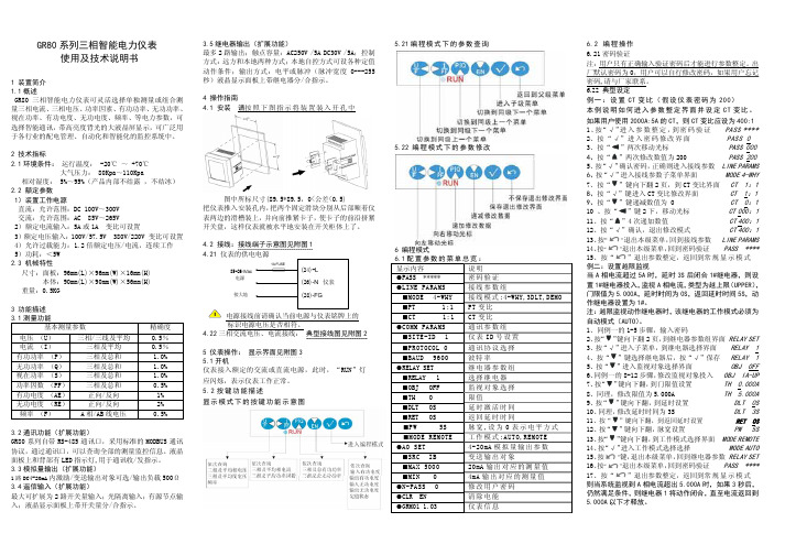
GR80系列三相智能电力仪表使用及技术说明书1 装置简介 1.1概述GR80三相智能电力仪表可灵活选择单独测量或组合测量三相电流、三相电压、功率因素、有功功率、无功功率、视在功率、有功电度、无功电度、频率、等电力参数,可选择智能通讯,带高亮度背光的大液晶屏显示,可广泛用于各行业的配电管理、自动化和智能化的监控系统中。
2 技术指标2.1环境条件: 运行温度: -20℃ ~ +70℃大气压力: 80Kpa~110Kpa相对湿度: 5%~95%(产品内部不结露 ,不结冰) 2.2 额定参数 1)装置工作电源直流:允许范围:DC 100V~300V 交流:允许范围:AC 85V~265V2)额定电流输入:5A 或1A 变比可设置3)额定电压输入:100V/57.5V 380V/220V 变比可设置 4)允许过载能力:1.2倍额定电压/电流,连续工作 5)功耗:<5W 2.3 机械特性尺寸:面板:96mm(L)×96mm(W)×16mm(H) 本体:90mm(L)×90mm(W)×56mm(H) 重量:0.5KG3 功能描述 3.1测量功能基本测量参数 精确度电压 (U) 三相/三线及平均0.5% 电流 (I) 三相及平均 0.5% 有功功率 (P) 三相及总和 1.0% 无功功率 (Q) 三相及总和 1.0% 视在功率 (S) 三相及总和 1.0% 功率因数 (PF) 三相及总和 0.5% 有功电度 (AE) 正向/反向1% 无功电度 (RE)正向/反向 2% 频率 (F) A 相/AB 线电压 0.5%3.2通讯功能(扩展功能)GR80系列自带RS-485通讯口,采用标准的MODBUS 通讯协议,通过通讯口,可以查询全部的测量监控信息。
液晶面板上和背部有LED 指示灯,用于通讯收/发指示。
3.3模拟量输出(扩展功能)1路DC4-20mA 内激励/变送输出对象可选/输出负载500Ω 3.4遥信输入(扩展功能)最大可扩展为2路开关量输入;光隔离输入;有源节点输入;液晶显示面板上带开关量分/合指示。
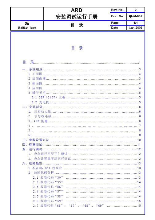
品质保证Team 目 录录Date Apr. 2009目 录目 录 (1)一、系统组成 (3)1 正面图 (3)2 后侧面图 (3)3 侧面图 (4)4 后面图 (4)5 板子说明 (5)5.1 DSP(2407)主板 (5)5.2 充电板 (5)二、安装部分 (6)1. 三相动力线 (6)2.信号线连接 (6)3. ARD接地 (6)4. (7)5. (8)6. (9)三、参数设置方法 (10)四、称重测试 (11)五、运行调试 (12)1. 应急运行平层开门调试 (12)2. 应急装置非平层运行调试 (12)六、故障处理 (13)1 不启动,K1A没吸合 (13)2 故障代码分析 (13)2.1 故障代码“30” (13)2.2 故障代码“33” (14)2.3 故障代码“56” (14)2.4 故障代码“57” (14)2.5 故障代码“58” (14)2.6 故障代码“59” (15)2.7 故障代码“66”、“67”、“68”、“69” (15)品质保证Team 目 录录Date Apr. 20092.8 故障代码“90” (15)2.9 故障代码“99” (15)2.10 故障代码“OF” (16)3 应急运行平层开门调试中常见故障 (16)3.1 不开门 (16)3.2 开门力矩不够 (16)3.3 开门过快 (16)4 非门区应急运行调试中常见故障 (16)4.1 数码管显示与电梯轿厢运行方向不一致 (16)4.2 平层精度调节 (16)七、蓄电池的说明 (16)八、DSP(2407)主板参数一览表 (19)品质保证 Team系统组成DateApr . 2009一、系统组成1 正面正面图图2 2 后侧面图后侧面图后侧面图说明:f. TS、TR、TT 为外电网三相380V 电源检测端子。
g. T1与T2、T3与T4、T5与T6为三组常闭点,用来隔离电梯控制变压器输入端。
品质保证Team 系统组成Date Apr. 2009品质保证 Team系统组成DateApr . 20095 5 板子说明板子说明板子说明5.1 DSP 主板5.2 充电板品质保证Team 参数设置方法Date Apr. 2009二、安装部分1. 三相动力线ARD三相动力线并联接在曳引机的三相输入2. 信号线连接3. ARD接地4. 电源检测及变压器隔离线品质保证 Team参数设置方法DateApr . 2009三、参数设置方法参数的设置是通过DSP 或LPC932主板上的4个按键实现的,各个键的功能: K 1—退出 ;K2—每按一次,使当前值递增;K3—每按一次,使当前值递减;K4—确定。

Agilent U8030 SeriesTriple-Output DC Power SuppliesData SheetAgilent extends its family of basic DC power supplies to include a one of a kind power supply that offers up to 375 W power at three outputs. Equipped with output sequencing capability, it allows you to generate output sequences even with minimal programming skills. Each power sup-ply is also built with excellent load regulation and clean output noise for continued stability. With these and many other features, you get a solid and reliable triple-output power sup-ply at an unsurpassed performance.The U8030 series offers twomodels- the U8031A and U8032A, each with different voltage andcurrent ratings to cater to your needs. Both models are well-regulatedcompact bench-tops with total output of 375 W, making it an ideal power source alternative in electronics manufacturing, research and develop-ment as well as education sector.Generate power supply output sequences -No ExtensiveProgramming Skills NecessaryThe output sequencing capability is carefully thought out for your convenience and ease when operating. Designed to perform automation function, our U8030 series is well-suited even for those with minimal programming skills. With easy-to-use knob and intuitive keypads, you can now set yourdesired output sequences for margin test, burn-in test and other general purpose tasks in an industrial setting.Higher Power. Better Reliability.Unrivalled Performance.Key Features• Provides total power of 375 W for three outputs• Output sequencing capability• Excellent load and line regulation (CV: < 0.01% + 2 mV; CC: < 0.02% + 2 mA) ensures stable output • Provides clean output with≤ 1 mVrms (0.5 mVrms typical) noise• Fast < 50 µs transient response for stable testing• Dual display shows both voltage and current reading• Over-voltage and over-current protection• Security features: keypad lock and physical lock mechanismUnrivalled Performance- With Low Output Noise and Excellent Load RegulationThe U8030 series provides excellent load and line regulation(CV: < 0.01% + 2 mV; CC: <0.02% + 2 mA) to ensure stable output even when load changes. This is crucial especially when dealing with noise-sensitive circuits that demand clean power. At a wide bandwidth of 20 Hz to 20 MHz, our bench power supplies continue to provide clean output at the lowest Vrms ≤ 1 mVrms (0.5 mVrms typical), leaving your signals uncontaminated and ensuring minimal interference to your Device-Under-Test (DUT).Added Safety Features-With OVP, OCPand Physical LockMechanismSafety is an important considerationwhen dealing with power. Users maynot only want to protect themselvesfrom exposure to current, but alsothe additional costs incurred to theirinvestment (DUT). Our U8030 seriespower supplies are integrated withan array of security features such asover-voltage (OVP) and over-current(OCP) protection to mitigate theserisks.Additionally, security features suchas keypad locking capability preventsaccidental front panel usage whilephysical lock mechanism which isstrategically located at the rear ofthe unit provides secure instrumentstorage.Differentiated Features-Allowing You to WorkBetterBoth models of the U8030 seriescome with a set of features to suityour needs while remaining easy touse. The LCD screen displays bothvoltage and current readings in a one-view panel while the all ON/OFF but-ton allows multiple outputs to be con-trolled simultaneously. Additionally,the auto-track feature simplifies setupbetween output 1 and output 2. Withthese, you get a solid bench powersupply plus a set of convenient andeasy to use features.Figure 1. Output sequencing made easy with intuitive keypads Figure 2. Backlight on/off feature withdual reading (voltage and current) on anLCD displayFigure 3. Simplifies Output 1 and Output 2setup with tracking featureFront Panel Descriptionwithout a PCLCD display:Channel control:Allows channels to be controlled individually/simultaneously (ON/OFF)Tracking:Auto-tracking between output 1 and output 2 with single controlEssential security features: Over-voltage protection (OVP)/Keypad lock/unlock:Locks front panel to prevent accidental changeFigure 4. The U8032A as illustratedKey SpecificationsElectrical SpecificationsTable 1.1 Electrical specifications 1U8031A U8032A Total power output (W)0 – 375 WVoltage output (V)Output Channel 1 & 2 (@ 0 to 40 °C)0 to 30 V 0 to 60 VCurrent output (A)Output Channel 1 & 2 (@ 0 to 40 °C)0 to 6 A 0 to 3 ANumber of outputs Three isolated outputs• Two variable: CV and CC operation• One fixed: CV operation only5 V fixed output 2 Output Channel 3• Voltage/Current output: 5 V, 3A• Output accuracy: ≤ 5% or (5 V ± 0.25 V) • Vrms: < 2 mVrms, or Vpp: < 50 mVpp • Load and line regulation: ≤ 5 mV• Overload condition: 3 A + 20% (typical)Line & load regulation (for variable output)CV: < 0.01% + 2 mV CC: < 0.02% + 2 mARipple & noiseBased on calculation at temp 18 - 28 °C and bandwidth at 20 Hz to 20 MHz CV: ≤1 mVrms, 0.5 mVrms(typical) or ≤ 10 mVpp, 5 mVpp(typical) CC: ≤ 1 mArmsLoad transient response timeWithin 15 mV from full load to half loadand from half load to full load< 50 usStability (output drift)Following 30 minutes warm-up, change in output over 8 hour under constant load, line, and ambient temperature.Voltage: < 0.02% Current: < 0.1%Programming accuracy (23 °C ± 5 °C)CV: ≤ 0.25% + 15 mVCC: ≤ 0.30% + 15 mAMeter readback accuracy (23 °C ± 5 °C)CV: ≤ 0.25% + 10 mVCC: ≤ 0.25% + 10 mAProgramming/meter resolution Voltage: 10 mV(4 digits)Current: 10 mA (3 digits)Maximum output float voltage±240 Vdc1. The specifications stated are based on a 1 hour warm-up period.2. Ripple and noise, load transient response time, stability (output drift), programming accuracy, and meter readback accuracy specificationsnot available for Output Channel 3.Physical characteristicsTable 1.2 Physical characteristicsU8031A/U8032ADisplay LCD with amber backlightRotary knob for reading adjustment YesSize4U, half rackDimensions (H x W x D)179.0 x 212.3 x 379.0 mmWeight8.2 kgSupplemental characteristicsTable 1.3 Supplemental characteristicsU8031A U8032ATemperature coefficient (for 12 months) ±(% of output + offset)Output• CV: (0.01% + 1 mV)/°C • CC: (0.01% + 1 mA)/°C OVP, OCP• CV: < 0.05%/°C• CC: < 0.05%/°COutput voltage overshootDuring turn-on or turn-off of AC power, if output control isset less than 1 V< 1 VVoltage programming speed to within 1 % of total excursion Up Full loadNo loadDown Full loadNo load 30 V60 V 80 ms80 ms30 ms150 ms200 ms100 ms30 ms300 msOver temperature protection YesLast memory setting enabled YesThree memory storage locations for voltage and current settings YesErasing non-volatile memory Yes, erasable through front panelRack mount capability Yes, front panel and rear have rack-mountable supportAC power input specificationsTable 1.4 AC power input specificationsU8031A/U8032AInput power option (selectable)100 Vac ± 10%, 47 to 63 Hz115 Vac ± 10%, 47 to 63 Hz230 Vac± 10%, 47 to 63 HzMaximum input power600 VAFuse External, located at the rear panelEnvironmental specificationsTable 1.5 Environmental specificationsU8031A/U8032AOperating temperature0 to 40 °CStorage temperature–40 to 70 °CHumidity15% RH (relative humidity) to 85% RH at 40 °C (non condensing) Altitude Up to 2000 mFan acoustic noise• No load: follow Agilent Class CO, 45 dB sound pressureand 50 dB sound power• Full load: follow Agilent Class GP, 55 dB sound pressureand 60 dB sound powerEnvironment of use• Installation category II• Pollution Degree 2Connection specificationsTable 1.6 Connection specificationsU8031A/U8032AOutput connections+Out, –Out, and chassis ground on the front panel.(Either positive or negative output terminal may be grounded or can beoperated floating at up to a maximum of 240 V off ground. Total outputvoltage to ground must not exceed 240 Vdc)Binding posts Output binding post located horizontally and side by sideI/O connections N/AAC input 3 pins standard IEC AC power connector with fuse and lineselection at the rearProtection featuresTable 1.7 Protection featuresU8031A U8032A Overvoltage protection accuracy ± (% of output + offset)< 0.5% +0.5 VOvervoltage protection programmable range0.1 to 33.0 V0.1 to 66.0 V Overvoltage protection response time< 10 msOvercurrent protection accuracy ± (% of output + offset)< 0.5% + 0.5 AOvercurrent protection programmable range0.1 to 6.6 A0.1 to 3.3 A Overcurrent protection response time< 10 msOrdering InformationIncluded documentation:U8030 Series Product Reference CD-ROMAdditional documentation:U8031A-ACF Japanese language user guide, printedU8031A-ABA English language user guide, printedU8032A-ACF Japanese language user guide, printedU8032A-ABA English language user guide, printedCalibration document:U8031A-UK6 Commercial calibration with test result dataU8032A-UK6 Commercial calibration with test result dataOther Options:E3600A-100 Test lead kitOption 1CM Rack-mount kitRack-mount kits:To rack-mount a single instrument:Adapter kit (P/N 5063- 9245)Revised: June 8, 2011Product specifications and descriptions in this document subject to change without notice.© Agilent Technologies, Inc. 2011Published in USA, December 14, 20115990-9321EN。


目录1 概述 (3)1.1ARD3智能电动机保护器符合相关标准中的要求 . ...................................................................................................... 3 1.2结构特点 ........................................................................................................................................... . (3)2 产品特点 (3)3 型号说明 (4)4 主要参数 (5)4.1技术指标 ........................................................................................................................................... .................................................... 5 4.2产品组成 ........................................................................................................................................... .................................................... 6 4.3功能配置 ........................................................................................................................................... . (6)5 接线与安装 . (7)5.1端子排列 ........................................................................................................................................... .................................................... 7 5.2端子编号 ........................................................................................................................................... .................................................... 8 5.3外形及安装尺寸 ........................................................................................................................................... .................................... 8 5.4专用电流互感器模块外形尺寸 ........................................................................................................................................... .. 10 5.5250A 外置电流互感器外形尺寸 . ......................................................................................................................................... .. 11 5.6800A 外置电流互感器外形尺寸 . ......................................................................................................................................... .. 11 5.7外置剩余电流互感器外形尺寸 ........................................................................................................................................... .. 12 5.8100A 以上主体与互感器连接线 . ......................................................................................................................................... .. 13 5.9ARD3-XX/X-72F显示模块外形尺寸 . (13)5.10ARD3-XX/X-90F显示模块外形尺寸 (13)5.11ARD3-XX/X-90L显示模块外形尺寸 (14)6 操作指南 (15)6.1一体式面板 . ......................................................................................................................................... .............................................. 15 6.2分体式 72F 面板 ........................................................................................................................................... .................................. 17 6.3分体式 90F 面板 ........................................................................................................................................... ................................. 17 6.4菜单设置流程 ........................................................................................................................................... ........................................ 18 6.5切换显示 ........................................................................................................................................... .................................................. 18 6.6系统参数设定 ........................................................................................................................................... ........................................ 19 6.7一体式、分体 72F 、分体 90F 功能参数设定 . ............................................................................................................ 19 6.8一体式、分体 72F 、分体 90F 故障代码 ........................................................................................................................ 22 6.9分体 90L 面板 . ......................................................................................................................................... (22)7 保护功能 (27)7.1保护设定参数 ........................................................................................................................................... ........................................ 27 7.2过载保护 ........................................................................................................................................... .................................................. 28 7.3断相 /不平衡保护 ........................................................................................................................................... ................................ 29 7.4剩余电流保护(接地 /漏电 . ......................................................................................................................................... ...... 29 7.5堵转保护 ........................................................................................................................................... ................................................. 29 7.6阻塞保护 ........................................................................................................................................... ................................................. 29 7.8起动超时保护 . ......................................................................................................................................... (30)7.9欠压保护 ........................................................................................................................................... .................................................. 30 7.10过压保护 ........................................................................................................................................... ................................................ 30 7.11功率保护 ........................................................................................................................................... ................................................. 30 7.12相序保护 ........................................................................................................................................... ................................................ 30 7.13外部故障保护 . ......................................................................................................................................... ....................................... 30 7.14温度保护 ........................................................................................................................................... ................................................. 30 7.15欠 /失电重起(抗晃电 . ......................................................................................................................................... .............. 30 7.16 TE 时间保护(适用于增安型电动机 . (30)8 各种起动方式接线图和 3C 认证试验报告 (32)8.1ARD3保护模式接线图 ........................................................................................................................................... ...................... 33 8.2ARD3直接起动模式接线图 ........................................................................................................................................... ............ 34 8.3ARD3双向起动模式接线图 ........................................................................................................................................... ............ 35 8.4ARD3星—三角起动模式接线图 . ......................................................................................................................................... .. 36 8.5ARD3自耦降压起动模式接线图 ..........................................................................................................................................37 8.6ARD3软起动模式接线图 . ......................................................................................................................................... .................. 38 8.7ARD3变频起动模式接线图 ........................................................................................................................................... ............ 39 8.8ARD3双速电机运转控制接线图 ..........................................................................................................................................40 8.9双速电机设置方法 ........................................................................................................................................... ........................... 41 8.10ARD3智能型电动机保护器 3C 试验检测项目汇总表和试验报告 (42)1 概述ARD3智能电动机保护器 (以下简称 ARD3 , 适用于额定电压至 AC 690V 、额定电流至 AC 800A 、额定频率为 50/60Hz的电动机。
ARD3电动机保护器 MODBUS 通信协议1 Modbus RTU 通信协议概述电气接口:RS485半双工波特率: 1200/4800/9600/19200/38400地址:由一个字节组成(8位二进制),十进制为0~255,系统中只使用1~247,其它保留 错误检测:数据格式:数据长度:每字节位:1位起始位、8位数据位(最小有效位先发送)、无奇偶校验、1位停止位 2 ARD3支持的modbus 功能码03(0x03)功能码: 读保持寄存器 06(0x06)功能码: 写单个保持寄存器 16(0x10)功能码: 写多个保持寄存器 注:1)主站写参数,如参数超出数据范围,按照异常码03(非法数据)回复。
2)主站写参数,使用16(0x10)功能码时,寄存器数量最大为10(20字节)。
数量超过10个,按照异常码02(非法数据地址)回复。
3)运行控制位、输出控制位只能使用06功能码写入。
4) 主站读参数,寄存器数据最大为10(20字节)。
数量超过10个,按照异常码02(非法数据地址)回复。
ARD3读写数据示例:3 ARD3智能型电动机保护器通讯地址表3.1 ARD3智能型电动机保护器通讯地址名称及地址如表1所示。
表1 ARD3智能型电动机保护器通讯地址名称及地址注:1)地址201~227、512~959为本公司内部使用地址,用户没有专用的仪器不得修改。
3.2 故障记录历史故障记录从EEPROM的256字开始,直到767字,EEPROM容量小于256字时,不做历史记录。
记录空间循环使用,最近的记录将覆盖最老的记录,每次故障的记录包括64个字节(即32个16位的字),本产品包括8组故障记录。
具体结构如表2所示。
表2 故障记录结构表3.3 实时时钟和固件信息ARD3智能型电动机保护器的故障记录功能带有实时时钟信息,实时时钟和固件信息结构详见表3所示。
表3 实时时钟和固件信息结构表4 异常应答4.1 非法功能 01主站询问报文格式:本协议没有用到0x08功能码,因此子站应答:4.2 非法数据地址02主站询问报文格式:06功能码寄存器地址错误,因此子站应答:4.3 非法数据值03主站询问报文格式:16功能码寄存器数值超过参数范围,视为数值错误,因此子站应答:11。