An anisotropic Phong BRDF model
- 格式:pdf
- 大小:1.76 MB
- 文档页数:7

灯光与材质分析VR灯光VR灯光主要分3种:平面光、半球光和球体光投影:是否对物体的光照产生阴影双面:用来控制灯光的双面都产生照明效果(当灯光类型为平面时有效,其它类型无效)不可见:用来控制最终渲染时是否显示VR灯的形状忽略灯光法线:控制灯光的发射是否按照光源的法线发射不衰减:物理世界中,所有的光线都是有衰减的,如果勾选这个选项,VR将不计算灯光的衰减效果天光入口:这个选项是把VR灯转换为天光,这时的VR灯就变成间接照明(GI),失去了直接照明。
当勾选时,投影、双面、不可见等参数将不可用,这些参数将被VR的天光参数取代存储发光贴图:勾选这个选项,同时间接照明(GI)里的一次反弹引擎选择发光贴图时,VR灯光的光照信息将保存在发光贴图里。
在渲染光子的时候将变慢,但出图渲染速度会提高很多。
当渲染完光子的时候,可以把这个VR灯光关闭或删除,它对最后的渲染效果没有影响,因为它的光照信息已经保存在发光贴图里影响漫反射:该选项决定灯光是否影响物体材质属性的漫反射影响高光反射:该选项决定灯光是否影响物体材质属性的高光影响反射:勾选该选项时,灯光将对物体的反射区进行光照,物体可以将光源进行反射细分:这个参数控制VR灯光的采样细分。
较低的值,杂点多,渲染速度快;较高的值,杂点少,渲染速度慢阴影偏移:该参数用来控制物体与阴影偏移距离,较高的值会使阴影向灯光的方向偏移标准材质介绍阴影类型:标准材质的最基本属性,也称反光类型。
一块布料和一块金属在光的照射下所呈现出的反光效果是完全不同的multi-layer(双非圆型高光):组合了两个Anisotropic(非圆型高光),每一个反光都可以拥有不同的颜色和角度,适用于表现抛光的表面特殊效果,例如缎纹、丝绸和光芒四射的油漆等(其中roughness为粗糙度,值为0时,与使用Blinn效果一样)oren-nayer-Blinn:Blinn的变种,看起来更柔和,更适合做一些较为粗糙的效果。
brdf 原理BRDF(双向反射分布函数)是计算机图形学中广泛使用的一种表面光照模型,用于描述物体表面对入射光的反射特性。
BRDF原理是指通过数学模型来描述光在物体表面上的反射和散射过程。
BRDF的原理基于光线追踪和光的物理特性,它考虑了光照的入射角度、物体表面的法线向量以及观察方向。
通过这些因素,BRDF 能够计算出在不同入射角度下的反射光强度。
BRDF通常用函数的形式表示,它将入射光照强度、入射角度、出射角度等参数作为输入,输出反射光的强度。
BRDF的计算可以分为两个步骤:入射光照强度的采样和反射光强度的计算。
在采样阶段,通过光线追踪方法来模拟光线与物体表面的相互作用,确定入射光照强度。
在计算阶段,根据入射光照强度的采样结果以及物体表面的法线向量等参数,利用BRDF函数来计算出反射光的强度。
在BRDF函数中,常用的模型包括Lambertian模型、Phong模型、Blinn-Phong模型等。
这些模型通过调整参数来模拟不同的物体材质特性,如漫反射、镜面反射等。
通过选择合适的BRDF模型和参数,可以实现逼真的光照效果。
BRDF的应用广泛存在于计算机图形学中,例如计算机游戏、电影特效、虚拟现实等领域。
在这些应用中,BRDF被用于计算物体表面的光照效果,使得渲染出的图像更加真实和细致。
除了BRDF,还有另一种相关的表面光照模型称为BSDF(双向散射分布函数)。
BSDF包含了BRDF的内容,并且还考虑了光线的透射和散射过程。
BSDF的原理与BRDF类似,但是更加复杂。
BSDF可以用于模拟透明物体的光照效果,如玻璃、水等。
总结起来,BRDF是一种用于描述物体表面光照特性的数学模型。
通过计算入射光照强度和物体表面的反射特性,BRDF能够实现逼真的光照效果。
在计算机图形学中,BRDF被广泛应用于各种渲染技术中,提供了逼真的光照效果,使得渲染出的图像更加真实和细致。
vray双向反射分布函数phong blinn 双向反射分布函数(BRDF)是计算机图形学中用于描述光线与表面相互作用的一种数学模型。
它包含了关于光线入射、反射和折射的信息,是渲染真实感光照效果的关键因素之一。
在计算机图形学中,常用的BRDF模型有Phong模型和Blinn-Phong 模型。
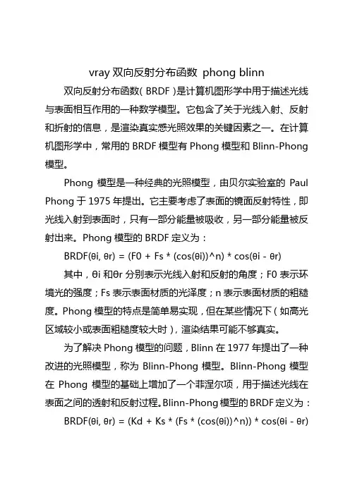
Phong模型是一种经典的光照模型,由贝尔实验室的Paul Phong于1975年提出。
它主要考虑了表面的镜面反射特性,即光线入射到表面时,只有一部分能量被吸收,另一部分能量被反射出来。
Phong模型的BRDF定义为:BRDF(θi, θr) = (F0 + Fs * (cos(θi))^n) * cos(θi - θr)其中,θi和θr分别表示光线入射和反射的角度;F0表示环境光的强度;Fs表示表面材质的光泽度;n表示表面材质的粗糙度。
Phong模型的特点是简单易实现,但在某些情况下(如高光区域较小或表面粗糙度较大时),渲染结果可能不够真实。
为了解决Phong模型的问题,Blinn在1977年提出了一种改进的光照模型,称为Blinn-Phong模型。
Blinn-Phong模型在Phong模型的基础上增加了一个菲涅尔项,用于描述光线在表面之间的透射和反射过程。
Blinn-Phong模型的BRDF定义为:BRDF(θi, θr) = (Kd + Ks * (Fs * (cos(θi))^n)) * cos(θi - θr)+ Kt * (1 - cos(θi - θr))其中,Kd表示漫反射系数;Ks表示镜面反射系数;Kt表示透射系数。
Blinn-Phong模型在保留Phong模型优点的同时,增加了对表面材质的漫反射和透射特性的描述,使得渲染结果更加真实。
V-Ray是一款广泛应用于计算机图形学的渲染引擎,它支持多种BRDF模型,包括Phong模型和Blinn-Phong模型。
在V-Ray中,用户可以通过调整材质参数来选择不同的BRDF模型,以实现所需的光照效果。
diffusion model简书(中英文实用版)Title: A Brief Introduction to Diffusion Models标题:扩散模型简述Diffusion models have gained immense popularity in the field of machine learning, particularly in the generation of images, text, and audio.扩散模型在机器学习领域变得非常流行,尤其是在图像、文本和音频的生成方面。
The core concept of diffusion models lies in simulating the process of data distribution evolving from a noisy state to a clean, high-quality state.扩散模型的核心概念是模拟数据分布从噪声状态演变为干净、高质量状态的过程。
These models are trained to reverse this process, effectively generating new, high-quality data from random noise.这些模型被训练来逆转这一过程,有效地从随机噪声生成新的、高质量的数据。
One of the key advantages of diffusion models is their ability to generate data with high fidelity and diversity, making them highly suitable for various applications such as image synthesis, text generation, and audio processing.扩散模型的一大优势是它们能够生成高保真度和多样性的数据,使它们非常适合各种应用,如图像合成、文本生成和音频处理。
基于BRDF模型的金属表面反射特性及相变特性研究张颖;李金龙;黄趾维;冯尧;杨露露;唐欣盈【期刊名称】《光电技术应用》【年(卷),期】2017(32)3【摘要】针对强反射金属表面物体的三维形貌测量问题,在传统光照度BRDF模型的基础上,详细研究了适合金属表面的Cook-Torrance反射模型,并结合菲涅尔公式对金属表面相变特性进行了分析.以常见几种金属可见光范围内的复折射率为例,对模型进行数值仿真,得出常见金属在不同波长下的镜面反射率和相移特性曲线,为金属表面物体的三维形貌测量等应用提供理论基础和方法指导.【总页数】4页(P32-35)【作者】张颖;李金龙;黄趾维;冯尧;杨露露;唐欣盈【作者单位】西南交通大学物理科学与技术学院,成都611756;西南交通大学物理科学与技术学院,成都611756;西南交通大学物理科学与技术学院,成都611756;西南交通大学物理科学与技术学院,成都611756;西南交通大学物理科学与技术学院,成都611756;西南交通大学物理科学与技术学院,成都611756【正文语种】中文【中图分类】TN219【相关文献】1.金属表面Ω介质涂层的电磁反射特性研究 [J], 周斌和;吴峰;厉位阳;周一峰;应金品;孙威2.频域分波法研究涂覆于金属表面的手征介质层的电磁反射特性 [J], 吴峰;李文扬3.基于BRDF的在轨卫星反射特性 [J], 王付刚;张伟;汪洪源4.基于PR-715测量的PVC材料BRDF特性与Phong模型研究 [J], 刘屹超;李宏宇;秦锋;邹纪平;冯洁;杨卫平5.基于Roujean和Ross-Li模型算法的不同户外光照南疆冬枣BRDF特性研究 [J], 索玉婷;罗华平;刘金秀;李伟;陈冲;徐嘉翊;王长旭因版权原因,仅展示原文概要,查看原文内容请购买。
双向反射分布函数反射成像
双向反射分布函数(BRDF)是描述物体表面反射性质的一种数学模型,它能够预测任意入射光线方向下的反射光线方向和强度。
BRDF 在计算机图形学、计算机视觉、遥感、光学等领域都有着广泛应用。
反射成像是指物体表面反射出的图像,它是由光线经过物体表面反射后形成的。
在计算机图形学中,反射成像是绘制真实场景的重要组成部分。
通过使用 BRDF 模型和反射成像技术,我们可以在计算机上渲染出高度逼真的图像。
BRDF 的计算过程可以分为两个部分:入射光线和出射光线的处理。
入射光线通常是通过光线跟踪技术确定的,而出射光线的方向和强度则由 BRDF 模型计算得出。
BRDF 模型通常包括反射率、粗糙度、金属度等参数,这些参数决定了物体表面的反射特性。
反射成像技术可以分为两种:离线渲染和实时渲染。
离线渲染通常用于生成高质量的静态图像,它可以利用 BRDF 模型预先计算出所有入射光线和出射光线的信息。
而实时渲染则需要在每一帧图像中动态计算出入射光线和出射光线的信息,因此需要更快的计算速度和更低的计算成本。
总之,BRDF 模型和反射成像技术对于计算机图形学和计算机视觉等领域都具有重要意义。
它们的应用使得计算机能够模拟真实世界的光学效果,从而生成出逼真的图像和场景。
- 1 -。
光照模型Lambert模型(漫反射)环境光:Iambdiff = Kd*Ia其中Ia 表⽰环境光强度,Kd(0<K<1)为材质对环境光的反射系数,Iambdiff是漫反射体与环境光交互反射的光强。
⽅向光:Ildiff = Kd * Il * Cos(θ)其中Il是点光源强度,θ是⼊射光⽅向与顶点法线的夹⾓,称⼊射⾓(0<=A<=90°),Ildiff是漫反射体与⽅向光交互反射的光强,若 N为顶点单位法向量,L表⽰从顶点指向光源的单位向量(注意顶点指向光源),则Cos(θ)等价于dot(N,L),故⼜有:Ildiff = Kd * Il * dot(N,L)最后综合环境光和⽅向光源,Lambert光照模型可以写成:Idiff = Iambdiff + Ildiff = Kd * Ia + Kd * Il * dot(N,L)Phong模型(镜⾯反射)Phong模型认为镜⾯反射的光强与反射光线和视线的夹⾓相关:Ispec = Ks * Il * ( dot(V,R) )^Ns其中Ks 为镜⾯反射系数,Ns是⾼光指数,V表⽰从顶点到视点的观察⽅向,R代表反射光⽅向。
由于反射光的⽅向R可以通过⼊射光⽅向L(从顶点指向光源)和物体的法向量求出,R + L = 2 * dot(N, L) * N 即 R = 2 * dot(N,L) * N - L所以最终的计算式为:Ispec = Ks * Il * ( dot(V, (2 * dot(N,L) * N – L ) )^NsBlinn-Phong光照模型(修正镜⾯光)Blinn-Phong是⼀个基于Phong模型修正的模型,其公式为:Ispec = Ks * Il * ( dot(N,H) )^Ns其中N是⼊射点的单位法向量,H是光⼊射⽅向L和视点⽅向V的中间向量,通常也称之为半⾓向量(半⾓向量被⼴泛⽤于各类光照模型,原因不但在于半⾓向量蕴含的信息价值,也在于半⾓向量是很简单的计算:H = (L + V) / |L + V| )。
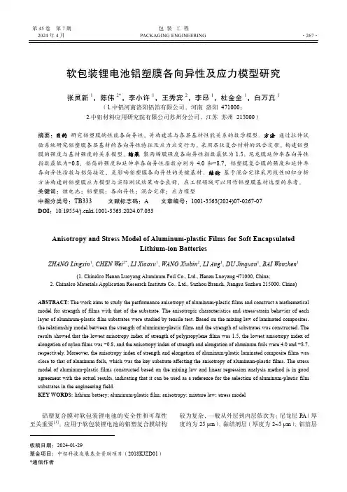
第45卷 第7期 包 装 工 程2024年4月PACKAGING ENGINEERING ·267·收稿日期:2024-01-29基金项目:中铝科技发展基金资助项目(2018KJZD01) 软包装锂电池铝塑膜各向异性及应力模型研究张灵新1,陈伟2*,李小许1,王秀宾2,李昂1,杜金全1,白万真1(1.中铝河南洛阳铝箔有限公司,河南 洛阳 471000; 2.中铝材料应用研究院有限公司苏州分公司,江苏 苏州 215000)摘要:目的 研究铝塑膜的性能各向异性,并构建其与各层基材性能关系的数学模型。
方法 通过拉伸试验系统研究铝塑膜各层基材的各向异性特征及应力应变行为,采用层状复合材料的混合定律,构建铝塑膜的强度与基材强度的关系模型。
结果 聚丙烯膜强度各向异性指数最低为1.5,尼龙膜延伸率各向异性指数最低为−0.8,铝箔的强度和延伸率各向异性指数分别为4.0和−8.7,铝塑膜复合膜的强度和延伸率各向异性指数与铝箔接近,是影响铝塑膜各向异性的关键基材。
结论 基于混合定律采用线性回归分析方法构建的铝塑膜应力模型与实际测试结果吻合良好,在工程领域可以用作铝塑膜基材选型的参考。
关键词:锂电池;铝塑膜;各向异性;混合定律;应力模型中图分类号:TB333 文献标志码:A 文章编号:1001-3563(2024)07-0267-07 DOI :10.19554/ki.1001-3563.2024.07.033Anisotropy and Stress Model of Aluminum-plastic Films for Soft EncapsulatedLithium-ion BatteriesZHANG Lingxin 1, CHEN Wei 2*, LI Xiaoxu 1, WANG Xiubin 2, LI Ang 1, DU Jinquan 1, BAI Wanzhen 1(1. Chinalco Henan Luoyang Aluminum Foil Co., Ltd., Henan Luoyang 471000, China;2. Chinalco Materials Application Research Institute Co., Ltd., Suzhou Branch, Jiangsu Suzhou 215000, China) ABSTRACT: The work aims to study the performance anisotropy of aluminum-plastic films and construct a mathematical model for strength of films with that of the substrate. The anisotropic characteristics and stress-strain behavior of each layer of aluminum-plastic film substrates were studied by tensile test. Based on the mixing law of laminated composites, the relationship model between the strength of aluminum-plastic films and the strength of substrates was constructed. The results showed that the lowest anisotropy index of strength of polypropylene films was 1.5, the lowest anisotropy index of elongation of nylon films was −0.8, and the anisotropy index of strength and elongation of aluminum foils were 4.0 and −8.7, respectively. Moreover, the anisotropy index of strength and elongation of aluminum-plastic laminated composite films was close to that of aluminum foils, which was the key substrate affecting the anisotropy of aluminum-plastic films. The stress model of aluminum-plastic films constructed based on the mixing law and linear regression analysis method is in good agreement with the actual results, indicating that it can be used as a reference for the selection of aluminum-plastic film substrates in the engineering field.KEY WORDS: lithium battery; aluminum-plastic film; anisotropy; mixture law; stress model铝塑复合膜对软包装锂电池的安全性和可靠性至关重要[1]。
等向性机械性质模型(Isotropic Mechanical Model)Moldex3D使用材料的线性弹性性质来计算翘曲的情形,其中所使用的等向性机械性质是杨式模数、波以松比及热膨胀系数。
在Moldex3D的现行版本,这三个参数都被假设为与温度无关。
因此在模拟时建议使用其室温下的性质。
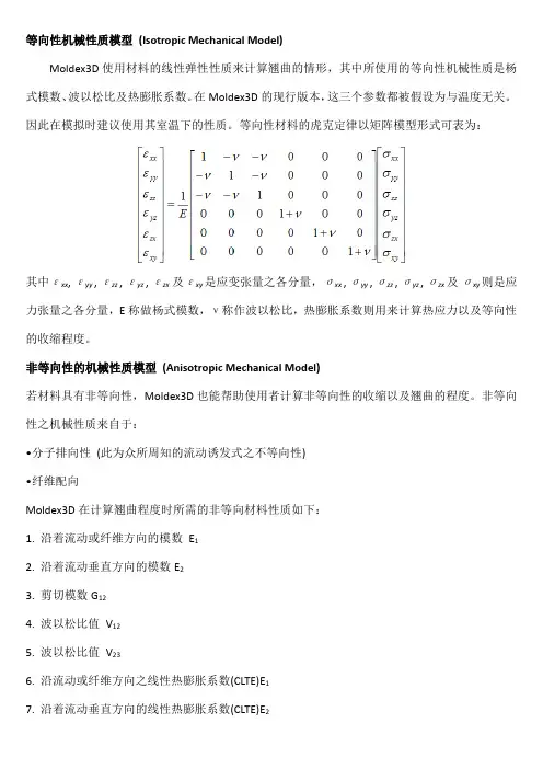
等向性材料的虎克定律以矩阵模型形式可表为:其中εxx,εyy,εzz,εyz,εzx及εxy是应变张量之各分量,σxx,σyy,σzz,σyz,σzx及σxy则是应力张量之各分量,E称做杨式模数,ν称作波以松比,热膨胀系数则用来计算热应力以及等向性的收缩程度。
非等向性的机械性质模型(Anisotropic Mechanical Model)若材料具有非等向性,Moldex3D也能帮助使用者计算非等向性的收缩以及翘曲的程度。
非等向性之机械性质来自于:•分子排向性(此为众所周知的流动诱发式之不等向性)•纤维配向Moldex3D在计算翘曲程度时所需的非等向材料性质如下:1. 沿着流动或纤维方向的模数E12. 沿着流动垂直方向的模数E23. 剪切模数G124. 波以松比值V125. 波以松比值V236. 沿流动或纤维方向之线性热膨胀系数(CLTE)E17. 沿着流动垂直方向的线性热膨胀系数(CLTE)E2我们可藉由标准的拉伸测试中获得沿着流动方向或垂直方向的的杨式模数E1及E2,如下图所示,我们也可依此方法求得波以松比。
流动方向/纤维配向及其横向之定义剪切模数被定义为剪应力与剪应变之比值。
剪切模数之定义若为一个含纤维的材料,在计算非等向之机械性质时,可能会用到长度与直径的比值(L/D)及重量百分比。
此时在计算orthotropic材料的非等向性翘曲时,以上参数将会被导入虎克定律,其中包括三个杨式模数E x、E y、E z、三个波以松比值V yz、V xy、V zx,以及三个剪切模数G yz、G xy、G z,orthotropic材料的统御方程式(Constitutive equation) 为:其中εij与σij分别为应变张量与应力张量。

空间相机常用金属材料表面的BRDF特性关洪宇;刘巨;于善猛;关奉伟【摘要】为保证空间相机热设计中表面辐射换热计算准确可靠,基于两种金属材料的光学常数,结合Monte Carlo射线跟踪法应用几何光学近似对其粗糙表面的双向反射分布函数(BRDF)进行了研究.分析了不同入射光波长、不同入射角度及不同表面粗糙度对金属铝和钛材料粗糙表面的BRDF的影响.结果表明,金属铝和钛材料粗糙表面的BRDF分布具有明显的镜反射特征,入射平面内的BRDF峰值随入射光波长增加而增大,在本文研究的波长范围内,钛表面的BRDF随入射光波长增大的增幅最高达到41.0%,远高于铝表面的8.7%.当表面粗糙度较大时,光子在粗糙表面内会经历多次散射,粗糙表面内多次散射光子数比例随着表面粗糙度的增大而增加,并且随着入射角度的增大具有增加的趋势.【期刊名称】《光散射学报》【年(卷),期】2016(028)001【总页数】7页(P77-83)【关键词】表面辐射;粗糙表面;几何光学近似;双向反射分布函数【作者】关洪宇;刘巨;于善猛;关奉伟【作者单位】中国科学院长春光学精密机械与物理研究所,吉林长春 130033;中国科学院长春光学精密机械与物理研究所,吉林长春 130033;中国科学院长春光学精密机械与物理研究所,吉林长春 130033;中国科学院长春光学精密机械与物理研究所,吉林长春 130033【正文语种】中文【中图分类】TK121空间相机对工作环境温度的变化非常敏感,由热引起的光机结构误差会导致相机的视轴漂移和光学系统的波前畸变,严重破坏成像质量。
为保证空间相机所需的工作温度水平,要求相机热设计准确可靠。
表面辐射换热是空间相机内部及与环境换热的主要形式之一,相机材料表面辐射特性数据对于热设计的准确性非常重要。
固体材料的表面辐射特性与物质种类、光照波长、入射角度、表面温度及表面状况等多种因素有关[1-2],针对某一特定条件下材料表面辐射特性数据往往不易获得。
熊健, 王彦斌, 吕阳, 姬忠莹, 张晓慧, 王晓龙, 李志强. 环氧树脂-水凝胶软硬复合表界面各向异性摩擦研究[J]. 摩擦学学报(中英文), 2024, 44(3): 335−344. XIONG Jian, WANG Yanbin, LYU Yang, JI Zhongying, ZHANG Xiaohui, WANG Xiaolong, LI Zhiqiang. Anisotropic Friction of Epoxy-Bydrogel Based Surfaces with Soft-Hard Combination[J]. Tribology, 2024, 44(3): 335−344. DOI: 10.16078/j.tribology.2023015环氧树脂-水凝胶软硬复合表界面各向异性摩擦研究熊 健1, 王彦斌1*, 吕 阳2, 姬忠莹2,3*, 张晓慧4, 王晓龙2,3, 李志强4(1. 西北民族大学 化工学院,甘肃 兰州 730030;2. 烟台先进材料与绿色制造山东省实验室,山东 烟台 264006;3. 中国科学院兰州化学物理研究所 固体润滑国家重点实验室,甘肃 兰州 730000;4. 西北民族大学 口腔医学国家民委重点实验室,甘肃 兰州 730030)摘 要: 由取向微结构引起的各向异性摩擦学是生物系统中最常见的引起摩擦形式之一. 而研究表明,软硬复合的生物表界面在获取各向异性摩擦力时更具有优势. 因此,本研究中以最典型的钩状倒刺微结构为研究对象,结合3D 打印先进制造技术,通过在仿生取向微结构表界面原位复合低模量的水凝胶材料,获得环氧树脂-水凝胶软硬复合表界面. 研究结果表明,水凝胶在Fe 3+溶液中的配位交联6 h 时,其模量为3.6 MPa ,相对于环氧树脂(模量为13.6 MPa)为软材料. 在5 N 载荷下,仿生表界面正方向摩擦力为1.64 N ,反方向摩擦力为3.44 N ,其各向异性摩擦力最大差值可达1.80 N. 本研究中对软硬复合的生物表界面具有一定的理论指导意义,有望在智能摩擦调控和软体机器人等方面发挥一定的作用.关键词: 仿生表界面; 水凝胶; 取向微结构; 各向异性摩擦力; 软硬复合中图分类号: TH117.1文献标志码: A文章编号: 1004-0595(2024)03–0335–10Anisotropic Friction of Epoxy-Bydrogel Based Surfaceswith Soft-Hard CombinationXIONG Jian 1, WANG Yanbin 1*, LYU Yang 2, JI Zhongying 2,3*,ZHANG Xiaohui 4, WANG Xiaolong 2,3, LI Zhiqiang4(1. School of Chemical Engineering, Northwest Minzu University, Gansu Lanzhou 730030, China;2. Shandong Laboratory of Advanced Materials and Green Manufacturing at Yantai, Shandong Yantai 264006, China;3. State Key Laboratory of Solid Lubrication, Lanzhou Institute of Chemical Physics,Chinese Academy of Sciences, Gansu Lanzhou 730000, China;4. Key Laboratory of Stomatology of State Ethnic Affairs Commission,Northwest Minzu University, Gansu Lanzhou 730030, China )Abstract : Anisotropic friction caused by oriented microstructure is one of the most common causes in biological systems. Typical examples like the snake locomotion with the aid of highly ordered fiber-like microstructures in ventral body side, the wheat awns propel the seeds on and into the ground with the help of silicified hairs that cover the awns,Received 4 February 2023, revised 25 March 2023, accepted 27 March 2023, available online 28 March 2023.*Corresponding author. E-mail: **************; E-mail: *************.cn, Tel: +86-151********.This project was supported from the National Natural Science Foundation of China (52005484, 52175201, 22165025).国家自然科学基金项目(52005484, 52175201, 22165025)资助.第 44 卷 第 3 期摩擦学学报(中英文)Vol 44 No 32024 年 3 月TribologyMar, 2024and the tree frogs have excellent wet attachment and friction performance can freely and repeatedly climb on vertical surfaces or overhang with the help of hierarchical pillar arrays. It has been demonstrated that the biological surface of soft-hard combination exhibits the more advantages for obtaining the anisotropic friction force, especially for the combination of hard structure and soft substrate. Even though the research of anisotropic friction based on the surface microstructures has obtained significant progress, the complicated preparation method, the little-span of modulus variation, and the unobvious switching of friction force are still limited the development of this project. Therefore, the hook-like spines, as one of the most effective topographies from various plants and animals for generating anisotropic force, were employed in this study. Furthermore, take advantages of additive manufacturing with the merits of creating sophisticated, bespoke and low-cost materials/devices, the surface with hook-like spines was prepared by a digital light process (DLP) 3D printer. And the optical microscope images displayed the printed surface was covered with hook-like spines exhibiting the same orientation and morphology, which were necessary for exploring the anisotropic friction force. In addition, for mimicking the typical combination of soft-hard combination and obtaining the dynamic friction force, the low modulus hydrogel was grown in-situ on the bionic oriented microstructures. To further enhance the mechanical performances, the prepared epoxy-hydrogel samples were immersed in Fe3+ solution for a secondary crosslinking by ionic coordination. The results demonstrated that with the increase of secondary cross-linked time, the hydrogel had an increased modulus. Integrating with the element of ruptured strain, the immersed time of 6 h was chosen with the modulus of 3.6 MPa and the ruptured strain of 288%. Comparing with epoxy resin, whose modulus was 13.6 MPa, the enhanced hydrogel was still a soft material. Finally, the anisotropic friction force of the prepared biomimetic epoxy-hydrogel surface under different conditions were investigated. Typically, when the normal load was increased from 1 N to 5 N, the negative friction force was greater than that of the positive friction force gradually. Importantly, with the normal increasing, the corresponding anisotropic friction force exhibited the larger difference. For example, under the 5 N load, the positive friction force of the biomimetic epoxy-hydrogel surface was 1.64 N, while the opposite sliding direction was 3.44 N, which showed the largest anisotropic friction difference. In this way, we demonstrated the prepared soft-hard surface had an isotropic friction force between positive and negative sliding directions at the lower normal load, while the friction force became anisotropic with the normal load increasing (>4 N). This study had a certain theoretical significance for the biological surface with the soft-hard combination, and was expected to play a certain role in intelligent frictional control, smart actuators and microbots, and some other friction-induced/controlled devices.Key words: biomimetic surfaces; hydrogels; oriented microstructure; anisotropic friction; soft-hard combination取向微结构表界面是生物系统中广泛存在的1种表面形态,是生物与其生活环境经过长期进化而形成的,是生物适者生存的1种选择[1]. 因此,生物的表面形态也必然会衍生出相应的功能. 如蛇在地面上蠕动行走时,其腹部鳞片与地面接触时产生不同方向的摩擦力,即各向异性摩擦力,进而推动蛇的蠕动前进[2-3]. 鲨鱼能够在水中达到56 km/h的速度是由于其表面皮肤的盾鳞结构,其样貌近似于对称的V形结构,而正是这些不同结构的V形沟槽表面存在着各向异性摩擦力,从而使其具有极佳的减阻效果[4-5]. 苍耳表面毛刺尖端结构排列具一定的取向性,而这种钩状物取向使其能够附着在人或动物身上完成种子传播与物种繁衍[6-7]. 受生物表界面形态-功能一体化的启发,为了研究生物取向微结构表界面的摩擦与黏附性能[8],科研人员发展了多种仿生表界面的构筑方法,包括模板法、激光刻蚀、纳米压印及3D打印等方法[9-12]. 然而,尽管已经报道的仿生表界面在形态与功能取得了一定的进展,但仍然存在着均一材料引起的仿生表界面形态功能不匹配、承载性能差以及功能性单一等缺点[12-13]. 事实上,已经有研究表明,很多生物表界面是由软硬两部分来构成,如苍蝇的爪垫、蜜蜂舌头上的刚毛和露珠草表面的钩刺等[14-16]. 这些生物表面的软硬分层结构在环境自适应性与功能性等方面表现出了一定的优势[17].本文中根据前期软硬复合仿生表界面的研究,选择最典型的钩状倒刺微结构作为取向表界面形态,利用商用的丙烯酸类光敏树脂和水凝胶材料,结合高精度的3D光固化打印机以及原位生长水凝胶的方法来构筑环氧树脂-水凝胶复合表界面. 通过对水凝胶不同时间的配位交联,系统研究了不同模量下仿生表界面的各向异性摩擦行为. 本研究有望对仿生摩擦学、软体机器人等领域提供一定的理论知识和技术指导[18-20].336摩擦学学报(中英文)第 44 卷1 试验部分1.1 试验原料光固化树脂二官能度双酚A 型环氧丙烯酸酯树脂光敏树脂(BAEA),三丙二醇二丙烯酸酯(TPGDA),1,6-己二醇二丙烯酸酯(HDDA)以及光引发剂二苯基-(2,4,6-三甲基苯甲酰)氧磷(TPO)购于成都四城新材料有限公司;丙烯酰胺(AM)、丙烯酸(AA)和阻聚剂柠檬黄溶液购于上海阿拉丁生化科技股份有限公司;光引发剂苯基2,4,6-三甲基苯甲酰基磷酸锂盐(LAP)购于广州贝奥吉因生物科技股份有限公司;交联剂聚乙二醇二甲基丙烯酸酯(PEGDA)购于上海光易化工有限公司;二苯甲酮和甲醇购于上海麦克林生化科技股份有限公司;六水三氯化铁购于北京百灵威科技有限公司;去离子水由实验室自制.1.2 3D 打印构筑环氧树脂基仿生表界面首先用天平称重环氧树脂BAEA 38.0 g ,活性稀释剂HDDA 30.0 g ,交联剂TPGDA 30.0 g ,光引发剂TPO 2.0 g ,置于球磨罐中然后用搅拌除泡机(ThinkyMixer ARE-310) 以3 000 r/min 的转速搅拌处理7 min 以达到溶液黏度均匀适合打印. 其次,如图1所示,用SoildWorks 三维软件设计钩状倒刺微结构模型并用摩方高精度3 D 打印机(MicroArch S240)进行层层打印,然后将打印好的树脂样品进行2 min 后固化处理. 具体的打印步骤为:首先将处理好的环氧树脂溶液缓慢倒入料槽,分别使用刮刀和滚刀除去薄膜气泡和铺平薄膜与溶液. 然后利用4个光点定位使得打印成型平台调平. 最后是导入模型并设定相关参数进行光固化打印. 在打印过程中分为6个阶段,第1阶段曝光1层,曝光时间为2 s ,光源曝光强度为150 mW ,打印平台下降距离为0 mm ,打印平台下降后停留时间0 s ,打印平台上升距离0 mm ,打印平台上升后停留时间250 s. 第2阶段曝光5层,曝光时间为1.5 s ,光源曝光强度为120 mW ,打印平台下降距离为4 mm ,打印平台下降后停留2 s ,打印平台上升距离3.975 mm ,打印平台上升后停留200 s.第3到5阶段曝光层数依次为14,30及107层,最后阶段(即第6阶段)曝光层数为45层,其他参数不变.Design model 3D printed pattern Samples of ligand Ferric chloride solution UV-initiated polymerizationUV irradiationAssemblyingBenzophenone solution Assembling hydrogel and resinFig. 1 Schematic diagram of preparing the epoxy-hydrogel surface with soft-hard combination.图 1 环氧树脂-水凝胶软硬复合表界面制备原理示意图1.3 环氧树脂-水凝胶复合表界面的构筑为了能够使得表面微结构能够更好地与水凝胶结合,如图1所示,首先用甲醇溶液和去离子水彻底清洗微结构的表面,用氮气吹使其完全干燥. 其次,将打印的微结构样品完全浸泡在二苯甲酮溶液(含质量分数为10%的乙醇)中,在室温下溶液完全覆盖整个样品表面5 min. 最后,用甲醇和去离子水反复清洗表面3次,并用氮气吹干. 用天平称单体丙烯酰胺(AM)21.324 g ,丙烯酸(AA) 3.603 g 与交联剂聚乙二醇二甲基丙烯酸酯(PEGDA) 0.373 g ,光引发剂苯基2,4,6-三甲基苯甲酰基磷酸锂盐(LAP) 0.124 g 混合并加入50 mL 去离子水,然后再用胶头滴管滴入5滴阻聚剂柠檬黄溶液并搅拌均匀使其成为水凝胶预聚体溶液,倒入装有微结构样品的玻璃载具中,通入氮气并存放1 h 左右. 此后,将打印处理后的表面微结构样品浸泡至水凝胶溶液中并使水凝胶溶液刚好覆盖表面微结构. 将第 3 期熊健, 等: 环氧树脂-水凝胶软硬复合表界面各向异性摩擦研究337环氧树脂-水凝胶溶液样品置于光源波长为365 nm的紫外箱进行光固化结合,在此期间与样品表面发生共价交联反应,使得水凝胶材料与环氧树脂材料结合的较为牢固. 其结合力在5 N载荷下能够满足相关的摩擦学测试需求,摩擦过程中没有发生剥离现象.图2所示为复合表面水凝胶化学/物理交联配位机理图. 在水凝胶聚合过程中,以聚乙二醇二甲基丙烯酸酯为化学交联剂,在室温下通过自由基聚合制备了丙烯酸-丙烯酰胺共聚水凝胶. 由于水凝胶内部是共价交联且无规网络,具有较低的交联度,从而使得水凝胶本身非常柔软且弹性大,在摩擦过程中表面容易起褶皱,无法进行表征测试. 因此,为进一步提升水凝胶的机械强度,将制备样品放入0.1 mol/L浓度的三氯化铁溶液中浸泡,使其进一步发生配位交联形成物理化学双网络体进而提升水凝胶的机械强度. 将不同样品分别浸泡2、4、6和8 h,浸泡完成后用大量的去离子水进行冲洗,进而除去样品表面的三氯化铁溶液,样品待用.1.4 测试表征摩擦学测试采用往复式摩擦磨损试验仪(Anton Paar CEM-THT07-135),选择的摩擦频率为0.01 Hz,摩擦对偶为聚二甲基硅氧烷(PDMS)半球,球的直径为6 mm. 对偶的滑动位移和滑动速度分别为8 mm和0.08 cm/s. 另外,为保证水凝胶的润湿性状态,在摩擦测试过程中复合表面通过手动滴水始终保证1层水膜的存在. 采用全自动3D超景深视频显微镜(DVM6A)观察其形貌特征和测量三维尺寸. 使用万能材料试验机(AGS-X 500N)对不同配位时间的水凝胶样品进行拉伸测试,选择拉伸速度为25 mm/min,每个样品拉伸5次,模量为其平均值.2 结果与讨论2.1 表面形貌本研究中选择具有高度取向性的钩状倒刺微结构为研究对象,其模型设计尺寸的基底为20 mm×20 mm×10 mm. 仿照绿鳍鱼鱼皮的表面微结构通过SolidWorks三维软件设计其尺寸,如图3所示,其表面微结构的钩状物高度(h)大约为800 μm,每个钩状物间距(s)约为750 μm,其根部直径(d)约为460 μm,钩状物弧度半径(r)约为1 000 μm. 根据设计模型,利用高精度摩方3D打印机仿生构筑表面微结构. 从超景深视频显微镜可以看出,表面微结构排列高度整齐,表明相对较为平滑,且微结构的尖端具有明显的取向性,展现出了表面各向异性摩擦的必备条件之一,如图3(b)和(c)以及图4(a)所示. 另外,通过表面微结构的三维轮廓图可以更加直观清晰地看出,微结构尺度与模型设计尺寸基本一致,证明了3D打印技术在仿生表面构筑方面的优越性[图3(d)和(e)].利用3D打印技术获得高精度表面微结构之后,如何在其表面原位复合软质水凝胶是本研究的关键.图4(b)所示为微结构表面原位生长水凝胶的情况,可NH2NH2Fe3+NH2NH2OOOOFerric ionDeionized waterPhysical crosslinkingRinsingFe3+ loading(b)Fig. 2 (a) Schematic diagram of chemical structures of hydrogel; (b) coordination mechanism of epoxy-hydrogel surface 图 2 (a)水凝胶组成化学结构式示意图;(b)软硬复合表界面水凝胶配位机理338摩擦学学报(中英文)第 44 卷以看出微结构表面已经完全被软质水凝胶所覆盖,包括倒刺之间的缝隙与尖端倒刺微结构. 这表明,前期所使用的二苯甲酮溶液和甲醇溶液对表面处理的抑氧效果非常好,能够实现环氧树脂与水凝胶的软硬复800750700650H e i g h t /μm600550Distance/μm250 μm(e)Fig. 3 (a) The 3D design and (b, c) optical micrographs of hook-like spines; (d) image of 3D profile and (e) profile curve图 3 (a)仿生表面微结构三维设计图;(b, c)仿生表面微结构在光学显微镜下的放大图;(d)仿生表面微结构的三维轮廓图和(e)剖面图曲线Fig. 4 Optical micrographs of biomimetic surfaces with oriented microstructure: (a) 3D printing biomimetic surface with orientedmicrostructures ;(b) epoxy-hydrogel interface; (c) processed epoxy-hydrogel surface by iron coordination图 4 仿生取向微结构表界面形貌的光学显微镜照片:(a) 3D 打印仿生表界面微结构;(b)环氧树脂-水凝胶复合表界面;(c)环氧树脂-水凝胶经过铁离子配位结合第 3 期熊健, 等: 环氧树脂-水凝胶软硬复合表界面各向异性摩擦研究339合. 图4(c)所示为将仿生表界面浸泡的三氯化铁溶液进行配位交联,进而实现水凝胶机械模量的进一步提升[21-22]. 可以看出,浸泡三氯化铁溶液的水凝胶宏观上从黄色变成了棕红色,定性地表明了水凝胶成功实现了配位交联. 另外,从超景深显微镜照片可以看出在配位交联过程中,尽管水凝胶表面有少量的水分失去,但其依然能够很好地锚固在环氧树脂表面,实现水凝胶的双网络交联,从而能够实现高承载与高频率的摩擦学测试.2.2 机械性能为进一步验证软硬复合表界面在各向异性摩擦学方面的优越性,采用双酚A环氧树脂为硬质基底材料,水凝胶为软质材料,并且在树脂模量固定的前提下,系统研究了水凝胶在不同配位时间下的机械性能变化. 首先,对环氧树脂的机械性能进行了分析,如图5(a)所示,发现其断裂伸长率为5.2%,弹性模量为13.6 MPa,表明其具有相对较高的硬度. 图5(b)所示为水凝胶的拉伸曲线图,可以看出随着水凝胶配位时间的增加,其断裂强度越来越高(从2.6 MPa增大至4.1 MPa),同时其断裂伸长率也随之从288 %降至149 %.在浸泡时间为4~6 h时,其应变约为浸泡2 h时的2倍.而当水凝胶配位时间为8 h时,其断裂伸长率最小,而断裂强度和模量却能够达到最大值,分别为288%和4.1 MPa. 这是因为在水凝胶配位交联过程中水凝胶发生失水. 图5(c)所示为不同浸泡时间下模量的变化趋势,可以清晰地看出,随着浸泡时间的增加,水凝胶的模量也几乎呈现线性增加的趋势. 简言之,通过简单的Fe3+溶液的浸泡,能够实现水凝胶的配位交联且进一步提升了水凝胶的机械强度,为后续摩擦测试提供了良好的基础.12159Stress/MPa615105Modulus/MPa3012345Strain/%6453Stress/MPa21050100150200250300Strain/%564Modulus/MPa3122468Immersed time/h(a)(b)(c)2 h4 h6 h8 hFig. 5 Mechanical properties of epoxy resin and post-processed hydrogel: (a) tensile curve and modulus of epoxy resin;(b) stretch curve of hydrogel for different soaking time and (c) elastic modulus diagram图 5 环氧树脂与后处理水凝胶的机械性能:(a)环氧树脂固化后的拉伸曲线与模量;(b)水凝胶在不同浸泡时间下的拉伸曲线和(c)弹性模量图2.3 仿生表界面各向异性摩擦研究将制备的环氧树脂-水凝胶复合样品进行摩擦学表征测试. 根据前述内容,本文中将各向异性摩擦力定义为对偶在不同滑动方向下的摩擦力绝对值. 基于此,将环氧树脂-水凝胶复合样品在三氯化铁溶液中进行浸泡进而实现配位交联,根据样品浸泡时间的不同,实现复合样品软材料之间的模量差异性. 如图6所示,研究发现随着载荷的增加,各向异性摩擦力也在随之增加. 当载荷为5 N时,在任意的水凝胶模量下均表现出了最大的各向异性摩擦力. 然而,复合样品浸泡配位6 h时,在载荷为5 N的情况下其各向异性摩擦力接近1.8 N [图6(c)],而在配位2、4和8 h时其各向异性摩擦力仅为0.03、0.74和0.05 N [图6(a)、(b)和(d)]. 这表明,在环氧树脂-水凝胶复合样品在浸泡6 h、5 N载荷下具有最大的各向异性摩擦力.为了探究摩擦力与水凝胶模量的变化,系统研究了复合表面在同一载荷下不同交联配位时间下的各向异性摩擦力并列于表1中. 可以看出,在5 N载荷、配位2 h条件下,△F (定义为正向的摩擦力与负方向摩擦力的差值绝对值)相对较小(0.03 N). 这是因为配位时间较短,复合表面是以水凝胶为主导的低摩擦表面.当浸泡时间为达到6 h时,水凝胶的模量相应升高至3.65 MPa,此时获得最大的△F (1.80 N),此时其各向异性摩擦力最明显. 当交联配位时间增加到8 h时,其弹性模量升高至4.42 MPa,但△F反而为降低至0.05 N.这是因为在摩擦过程中PDMS对偶被大面积磨损,尽管正反方向摩擦力分别升高至3.20和3.25 N,但两者差值绝对值,即各向异性摩擦力仍然相对较低.为进一步证明交联配位时间为6 h,载荷为5 N时的各向异性摩擦力最大,利用光学显微镜分别观察了340摩擦学学报(中英文)第 44 卷不同浸泡时间下的复合表面与摩擦对偶的表面形貌.如图7(a)所示,环氧树脂-水凝胶复合表面在1~6 N 的载荷下表界面磨损痕迹相对较轻,当载荷为5 N 时,复合表面上的水凝胶存在轻微磨损,通过相对应的摩擦对偶照片,如图7(b)所示,可以看出随着载荷的增加,PDMS 对偶划痕逐渐加深. 当载荷增加到6 N 时,复合表面上的钩状物微结构已经有较为严重的磨损,而相对应的PDMS 对偶则同样被微结构划破刺穿. 这表明,当载荷为6 N 时,摩擦过程中承受载荷法向力的是复合表面中的环氧树脂. 此时,正反方向均有较大的摩擦力,进而导致各向异性摩擦力相对较小.综上所述,环氧树脂-水凝胶复合表面在交联配位时间为6 h 、载荷为5 N 时具有最大的各向异性摩擦力. 究其原因,当样品浸泡时间较短时,三价铁离子与羧基螯合反应率低,进而导致水凝胶模量较低. 而在低载荷下,复合样品的微结构表面是形成的以水凝胶为主体的超低摩擦表面,因此样品整体摩擦力数值比较小,导致其各向异性摩擦力没有体现出来. 当复合样品浸泡配位6 h 时,水凝胶配位交联程度适中,水凝胶网状物中间的空隙就像1张捕鱼网一样被逐渐收缩拉紧,诱导水凝胶模量增加,从而导致在摩擦过程中在低载荷下水凝胶起作用,各向异性摩擦力相对较小;而在高载荷下,复合表面取向微结构起作用,进而获得较大的各向异性摩擦力. 当样品浸泡时间增加到8 h 时,随着摩擦载荷的增加,尽管各向异性摩擦力也随之增加,但在5 N 载荷下其数值仍然相对较小(与配位6 h 时相比较). 这是因为当复合样品配位交联时间过长时,水凝胶配位交联彻底,形成了具有极为致密网络的水凝胶. 虽然其模量较大,但在摩擦过程中,PDMS 摩擦对偶无法摩穿微结构表面的致密水凝胶,因此无法与取向微结构的钩状倒刺结构进行接触,从而导致各向异性摩擦力相对较小. 为进一步观察复合10.81.0Load/N0.6F r i c t i o n f o r c e /N 0.40.20.0234510.040.05Load/N0.03F r i c t i o n f o r c e /N0.020.010.00234510.50.6Load/N0.4F r i c t i o n f o r c e /N0.30.20.00.1234511.62.0Load/N1.2F r i c t i o n f o r c e /N0.80.40.02345(a) 2 h(b) 4 h(c) 6 h (d) 8 hFig. 6 Anisotropic frictional values of epoxy-hydrogel surfaces at the coordination times of (a) 2 h,(b) 4 h, (c) 6 h and (d) 8 h with different applied loads图 6 环氧树脂-水凝胶复合表面在配位时间为(a) 2 h 、(b) 4 h 、(c) 6 h 以及(d) 8 h 时在不同载荷下的各向异性摩擦力表 1 相同载荷下水凝胶模量和各向异性摩擦力随浸泡时间的变化Table 1 The changes of hydrogel modulus and anisotropic friction force with different immersing times at 5 N loadImmersing time/hModulus/MPa△F /N 2 1.530.034 2.630.746 3.65 1.8084.420.05第 3 期熊健, 等: 环氧树脂-水凝胶软硬复合表界面各向异性摩擦研究341表面的各向异性摩擦力,选择最典型的具有各向异性摩擦力最大值的配位6 h的摩擦测试曲线进行观察,如图8所示. 其中,将摩擦对偶滑动方向与微结构取向一致定义为正方向摩擦力,摩擦对偶滑动方向与微结构取向相反定义为反方向摩擦力[图8(a)]. 可以看出,随着载荷的增加,复合表界面的摩擦各向异性越来越明显. 当载荷增加到5 N时,正方向的摩擦力为1.64 N,反取向摩擦力最大值为3.44 N,正反方向摩擦力差值可达1.80 N. 此外,可以清晰地看出正方向和反方向的摩擦曲线振幅相对平稳[图8(b~f)],说明环氧树脂-水凝胶复合表面摩擦力重复性较好. 简而言之,通过此种软硬复合的方法,能够实现表面各向异性摩擦力在不同载荷下的动态调控,即低载荷下摩擦对偶能够与软质水凝胶相接触,复合表面不具有或具有较低的各向异性摩擦力;而在高载荷下摩擦对偶与硬质取向微结构相接触,复合表面具有较大的各向异性摩擦力.3 结论本文中以软硬复合表面为研究对象,采用高精度3D光固化打印技术,结合水凝胶原位生长方法构筑了仿生取向环氧树脂-水凝胶复合表面. 在此基础上,为了更好地探究其各向异性摩擦行为,将制备的复合表界面浸泡于三氯化铁溶液中,使溶液中的三价铁离子与水凝胶溶液中的羧基进行螯合配位形成化学/物理双交联的三维网状结构,进而提高水凝胶模量,支撑其完成相关的摩擦学测试. 研究结果表明,通过控制(a)(b)Fig. 7 The wear morphologies of epoxy-hydrogel and PDMS pairs that after friction tests with different loads: (a) wear micrographs of epoxy-hydrogel surfaces with different loads; (b) wear morphologies of PDMS pairs with different loads 图 7 环氧树脂-水凝胶复合表面在不同载荷下的复合表面磨损与对偶磨损图:(a)复合表面在不同载荷下的磨损图;(b)摩擦对偶在不同载荷下的磨损图342摩擦学学报(中英文)第 44 卷时间可以获得不同模量的水凝胶. 在配位交联6 h 时水凝胶模量为3.6 MPa. 在5 N 摩擦载荷下,此时软硬复合表界面具有最为明显的摩擦各向异性,正方向摩擦力为1.64 N ,反方向摩擦力为3.44 N ,正反方向的摩擦力差值为 1.80 N. 本研究基于环氧树脂和水凝胶来构筑具有软硬复合的仿生表界面,相信可以为智能摩擦调控及软体机器人等领域的发展提供技术和理论指导.参 考 文 献Sevilla P, Gil J, Aparicio C. Relevant properties for immobilizingshort peptides on biosurfaces[J]. IRBM, 2017, 38(5): 256–265. doi:10.1016/j.irbm.2017.06.003.[ 1 ]Abdel-Aal H A, El Mansori M, Zahouani H. A comparative study offrictional response of shed snakeskin and human skin[J]. Wear,2017, 376–377: 281–294. doi:10.1016/j.wear.2016.12.055.[ 2 ]Baum M J, Kovalev A E, Michels J, et al. Anisotropic friction of the ventral scales in the snake lampropeltis getula californiae[J].Tribology Letters, 2014, 54(2): 139–150. doi: 10.1007/s11249-014-0319-y.[ 3 ]Gabler-Smith M K, Lauder G V. Ridges and riblets: shark skinsurfaces versus biomimetic models[J]. Frontiers in Marine Science,2022, 9: 975062. doi: 10.3389/fmars.2022.975062.[ 4 ]Pu Xia, Li Guangji, Liu Yunhong. Progress and perspective ofstudies on biomimetic shark skin drag reduction[J]. ChemBioEng Reviews, 2016, 3(1): 26–40. doi: 10.1002/cben.201500011.[ 5 ]Abbas H K, Pantone D J, Paul R N. Characteristics of multiple-[ 6 ]seeded cocklebur: a biotype of common cocklebur (xanthium strumarium L.)[J]. Weed Technology, 2017, 13(2): 257-263. doi: 10.1017/s0890037x00041701.Li J, Ma M. Seeds over-wintering characteristics of ItalianCocklebur and Stab Cocklebur: two invasive plants in Xinjiang,China[J]. South African Journal of Botany, 2019, 121: 216–218. doi:10.1016/j.sajb.2018.10.032.[ 7 ]Jagota A, Hui C Y. Adhesion, friction, and compliance of bio-mimetic and bio-inspired structured interfaces[J]. Materials Scienceand Engineering:R:Reports, 2011, 72(12): 253–292. doi: 10.1016/j.mser.2011.08.001.[ 8 ]Liu Quan, Tan Di, Meng Fandong, et al. Adhesion enhancement ofmicropillar array by combining the adhesive design from gecko and tree frog[J]. Small, 2021, 17(4): 2005493. doi: 10.1002/smll.202005493.[ 9 ]Pang Minghua, Zhai Shuaijie, Feng Qigao, et al. Liquid-phaseassisted laser preparation of cemented carbide surface textures and study on their tribological properties[J]. Tribology, 2022, 42(5):1001–1011 (in Chinese) [逄明华, 翟帅杰, 冯启高, 等. 硬质合金表面织构液相辅助激光制备及摩擦性能[J]. 摩擦学学报, 2022,42(5): 1001–1011]. doi: 10.16078/j.tribology.2021200.[10]Tuo Yanjing, Zhang Haifeng, Rong Wanting, et al. Drag reductionof anisotropic superhydrophobic surfaces prepared by laser etching[J]. Langmuir, 2019, 35(34): 11016–11022. doi: 10.1021/ngmuir.9b01040.[11]Ma Shuanhong, Scaraggi M, Yan Changyou, et al. Bioinspired 3Dprinted locomotion devices based on anisotropic friction[J]. Small,[12]1F r i c t i o n f o r c e /N0−150100150200Time/s2503000−220.40.2F r i c t i o n f o r c e /N0.0−0.2−0.450100150200Time/s250300−0.60.62F r i c t i o n f o r c e /N0−250100150200Time/s2503000−442F r i c t i o n f o r c e /N0−250100150200Time/s2503000−4421F r i c t i o n f o r c e /N0−1−250100150200Time/s2503000−33LoadNegativePositive 1 N 0.01 Hz Positive Negative2 N 0.01 Hz Positive Negative4 N 0.01 Hz Positive Negative3 N 0.01 Hz (a)(d)(b)(e)(c)(f)Positive Negative5 N 0.01 Hz Positive NegativeFig. 8 (a) Schematic diagram of positive and negative friction; Frictional curves of epoxy-hydrogel surfacesunder the loads of (b) 1 N, (c) 2 N, (d) 3 N, (e) 4 N and (f) 5 N图 8 (a)正反方向摩擦力示意图;环氧树脂-水凝胶复合表面在(b) 1 N 、(c) 2 N 、(d) 3 N 、(e) 4 N 和(f) 5 N 载荷下的摩擦力曲线第 3 期熊健, 等: 环氧树脂-水凝胶软硬复合表界面各向异性摩擦研究343。
Geometric ModelingGeometric modeling is a crucial aspect of computer-aided design (CAD) and computer graphics. It involves the creation of digital representations of objects and environments using mathematical algorithms and geometric techniques. These models are used in various fields such as engineering, architecture, animation, and virtual reality. Geometric modeling plays a significant role in the design and visualization of complex structures, the simulation of physical phenomena, and the creation of realistic computer-generated imagery. One of the primary challenges in geometric modeling is achieving accuracy and precision in representing real-world objects and scenes. This requires the use of advanced mathematical concepts such as calculus, linear algebra, and differential geometry. Geometric modeling also involves the use of computational algorithms to generate and manipulate geometric shapes, surfaces, and volumes. These algorithms need to be efficient and robust to handle large-scale and intricate models while maintaining visualfidelity and integrity. Another important aspect of geometric modeling is the representation of 3D objects in a 2D space, which is essential for visualization and rendering. This process involves techniques such as projection, rasterization, and rendering, which are used to convert 3D geometric data into 2D images for display on screens or print. Achieving realistic and visually appealing representations requires careful consideration of lighting, shading, and texture mapping, which are fundamental in computer graphics and visualization. Inaddition to the technical challenges, geometric modeling also raises issuesrelated to usability and user experience. Designing intuitive and user-friendly interfaces for creating and manipulating geometric models is crucial for enabling efficient and effective design workflows. This involves considerations such as interactive manipulation, real-time feedback, and intuitive control mechanisms, which are essential for empowering users to express their creative ideas and concepts. Furthermore, geometric modeling has a significant impact on the manufacturing and production processes. The digital models created through geometric modeling are used for computer-aided manufacturing (CAM) and numerical control (NC) machining, enabling the production of precise and complex parts and assemblies. This integration of geometric modeling with manufacturing technologieshas revolutionized the way products are designed, prototyped, and manufactured, leading to advancements in efficiency, quality, and innovation. From an academic perspective, geometric modeling is a multidisciplinary field that draws from mathematics, computer science, and engineering. Researchers and educators in this field are constantly exploring new methods and techniques for geometric modeling, pushing the boundaries of what is possible in terms of representing and manipulating geometric data. This includes areas such as parametric modeling, geometric constraints, and procedural modeling, which are essential for enabling flexible and adaptable design processes. In conclusion, geometric modeling is a complex and multifaceted field with far-reaching implications for various industries and disciplines. It encompasses technical challenges related to accuracy, efficiency, and visualization, as well as considerations of usability, manufacturing, and academic research. As technology continues to advance, geometric modeling will play an increasingly critical role in shaping the way we design, create, and interact with the world around us.。
VR室内常用材质参数3d中的一些材质参数金属颜色色彩亮度漫射镜面光泽度反射凹凸(%)铝箔180.180.180 有32 90 中65 8 铝箔(钝)180.180.180 有50 45 低35 15 铝220.223.227 有35 25 低40 15 磨亮的铝220.223.227 有35 65 中50 12 黄铜191.173.111 有40 40 中40 20 磨亮的黄铜191.173.111 有40 65 中50 10 镀铬合金150.150.150 无40 40 低25 35镀铬合金 2 220.230.240 有25 30 低50 20 镀铬铝220.230.240 有15 60 中65 10 镀铬塑胶220.230.240 有15 60 低50 10 镀铬钢220.230.240 有15 60 中70 5 纯铬220.230.240 有15 60 低85 5 铜186.110.64 有45 40 中40 10 18K金234.199.135 有45 40 中65 10 24K金218.178.115 有45 40 中65 10 未精练的金255.180.66 有35 40 中45 25 黄金242.192.86 有45 40 中65 10 石墨87.33.77 无42 90 中15 10 铁118.119.120 有35 50 低25 20 铅锡锑合金250.250.250 有30 40 低15 10 银233.233.216 有15 90 中45 15 钠250.250.250 有50 90 低25 10 废白铁罐229.223.206 有30 40 低45 30 不锈钢128.128.126 有40 50 中35 20 磨亮的不锈钢220.220.220 有35 50 低25 35 锡220.223.227 有50 90 低35 20 净化瓶27.108.131 无90 60 低 5 20泡沫塑胶54.53.53 无95 30 低 3 90 合成材料20.20.20 无80 30 低 5 20 合成材料(粗糙)25.25.25 无60 40 低 5 20 合成材料(光滑)38.38.38 无60 30 低0 10 合成材料(钝)25.25.25 有92 40 低15 30 塑胶20.20.20 无80 30 低 5 10 塑胶(高光泽)20.20.20 无70 90 高15 5 塑胶(硬儿亮)20.20.20 无80 80 中10 10 塑胶(糖果衣)200.10.10 无80 30 低5 15 塑胶(巧克力色)67.40.18 无90 30 低 5 5 橡胶30.30.30 有30 20 低0 50 橡胶纽扣150.150.150 无60 20 低0 30 乙烯树脂45.45.45 无60 40 低15 301,水珠反光类型――phong-高光区光滑――玻璃,塑料等反光强度――72 光滑度―――48 index of refraction――-1.33 反射贴图――raytrace――背景颜色――墨绿色――代替环境,较快渲染――amt――60 折射贴图――thin wall refraction――产生物体间的折射效果2,树叶双面材质或多重子材质diffuse――不同的位图贴图bump贴图3,海水思路:先表现海水颜色,在表现波浪起伏,最后设置海水反射diffuse――swirl贴图――深蓝色和兰黑色bump――noise――可调噪波尺寸来表现海浪的大小反射贴图――raytrace 4,天空背景一个位图贴图――关键是根据场景调贴图的重复次数和偏移量天空模型可用半球或圆柱――法线翻转5,破裂的屋顶blend材质――transition zone――交换区域――通过调节数值来控制曲线的形状,当两个值接近时,贴图的黑白过渡区会产生清晰尖锐的融合边缘,反之则产生模糊的融合边缘材质1―――diffuse――noise贴图――color1――暗褐色,color2――暗黄色size――20 bump――noise―――――――――amount――690――强烈凹凸材质2――填充第一种的凹陷区域,还要表现裂纹效果diffuse――noise――color1:暗褐色,color2:浅褐色,size:3 bump――marble――黑,白―――40amt 融合设置:mix amt:706,立柱(带竖条纹理和灰尘腐蚀效果的水泥柱)compositors 基本材质――水泥diffuse――noise――color1:灰,color2:白size:8 bump――noise――黑,白size:2。
An Anisotropic Phong BRDF ModelMichael Ashikhmin Peter ShirleyAugust13,2000AbstractWe present a BRDF model that combines several advantages of the various empirical models cur-rently in use.In particular,it has intuitive parameters,is anisotropic,conserves energy,is reciprocal,hasan appropriate non-Lambertian diffuse term,and is well-suited for use in Monte Carlo renderers.1IntroductionPhysically-based rendering systems describe reflection behavior using the bidirectional reflectance distri-bution function(BRDF).For a detailed discussion of the BRDF and its use in computer graphics see the volumes by Glassner[2].At a given point on a surface the BRDF is a function of two directions,one toward the light and one toward the viewer.The characteristics of the BRDF will determine what“type”of material the viewer thinks the displayed object is composed of,so the choice of BRDF model and its parameters is important.We present a new BRDF model that is motivated by practical issues.A full rationalization for the model and comparison with previous models is provided in a seperate technical report[1].The BRDF model described in the paper is inspired by the models of Ward[8],Schlick[6],and Neimann and Neumann[5].However,it has several desirable properties not previously captured by a single model. In particular,it1.obeys energy conservation and reciprocity laws,2.allows anisotropic reflection,giving the streaky appearance seen on brushed metals,3.is controlled by intuitive parameters,4.accounts for Fresnel behavior,where specularity increases as the incident angle goes down,5.has a non-constant diffuse term,so the diffuse component decreases as the incident angle goes down,6.is well-suited to Monte Carlo methods.The model is a classical sum of a“diffuse”term and a“specular”term.ρ(k1,k2)=ρs(k1,k2)+ρd(k1,k2).(1) For metals,the diffuse componentρd is set to zero.For“polished”surfaces,such as smooth plastics,there is both a diffuse and specular appearance and neither term is zero.For purely diffuse surfaces,either the traditional Lambertian(constant)BRDF can be used,or the new model with low specular exponents can be used for slightly more visual realism near grazing angles.The model is controlled by four paramters:•R s:a color(spectrum or RGB)that specifies the specular reflectance at normal incidence.n v= 10000n v= 1000n v= 100n v= 10n u = 10n u = 100n u = 1000n u = 10000Figure1:Metallic spheres for various exponents.•R d:a color(spectrum or RGB)that specifies the diffuse reflectance of the“substrate”under the specular coating.•n u,n v:two phong-like exponents that control the shape of the specular lobe.We now illustrate the use of the model in severalfigures.After that,the remainder of the paper deals with specifying and implementing the model.Figure1shows spheres with R d=0and varying n u and n v.The spheres along the diagonal have n u=n v so have a look similar to the traditional Phong model.Figure2 shows another metallic object.This appearance is achieved by using the“right”mapping of tangent vectors on the surface.Figure3shows a“polished”surface with R s=0.05.This means the diffuse component will dominate for near normal viewing angles.However,as the viewing angle becomes oblique the specular component dominates despite its low near-normal value.Figure4shows the model for a diffuse surface. Note how the ball on the right has highlights near the edge of the model,and how the constant-BRDF ball on the left is more“flat”.The highlights produced by the new model are present in the measured BRDFs some paints,so are desirable for some applications[4].Figure2:A cylinder with the appearance of brushed metal created with the new model with R d=0,R s= 0.9,n u=10,n v=100.Figure3:Three views for n u=n v=400and a red substrate.Figure4:An image with a Lamertian sphere(left)and a sphere with n u=n v=5.After afigure from Lafortune et al.[4].2The ModelThe specular componentρs of the BRDF is:ρs(k1,k2)=(n u+1)(n v+1)8π(n·h)n u cos2φ+n v sin2φ(h·k)max((n·k1),(n·k2))F((k·h))(2)In our implementation we use Schlick’s approximation to Fresnel fraction[6]:F((k·h))=R s+(1−R s)(1−(k·h))5,(3) a·b scalar(dot)product of vectors a and bk1normalized vector to lightk2normalized vector to viewern surface normalu,v tangent vectors that form an orthonormal basis along with n.ρ(k1,k2)BRDFh normalized half-vector between k1and k2p(k)probability density function for reflection sampling raysF(cosθ)Fresnel reflectance for incident angleθTable1:Important terms used in the paperFigure5:Geometry of reflection.Note that k1,k2,and h share a plane,which usually does not include n. where R s is material’s reflectance for the normal incidence.It is not necessary to call trigonometric functions to compute the exponent in Equation2,so the specular BRDF can be written:ρs(k1,k2)=(n u+1)(n v+1)(n·h)(n u(hu)2+n v(hv)2)212F((k·h)).(4)in a It is possible to use a Lambertian BRDF together with our specular term in a way similar to that which is done for most models[6,8].However,we use a simple angle-dependent form of the diffuse component which accounts for the fact that the amount of energy available for diffuse scattering varies due to the dependence of specular term’s total reflectance on the incident angle.In particular,diffuse color of a surface disappears near the grazing angle because the total specular reflectance is close to one in this case.This well-known effect cannot be reproduced with a Lambertian diffuse term and is therefore missed by most reflection models.Another,perhaps more important,limitation of the Lambertian diffuse term is that it must be set to zero to ensure energy conservation in the presence of a Fresnel-weighted term.The diffuse term is:ρd(k1,k2)=28R d23π(1−R s)1−1−(n·k1)251−1−(n·k2)25(5)Note that our diffuse BRDF does not depend on n u and n v.The somewhat unusual leading constant is designed to ensure energy conservation.3Using the BRDF model in a Monte Carlo settingIn a Monte Carlo setting we are interested in the following problem:given k1,generate samples of k2with a distribution which shape is similar to the cosine weighted BRDF.This distribution should be a probability density function(pdf),and we should be able to evaluate it for a given randomly generated k2.The key part of our thinking on this is inspired by discussion by Zimmerman[9]and by Lafortune[3]who point out that greatly undersampling a large value of the integrand is a serious error while greatly oversampling a small value is acceptable in practice.The reader can verify that the densities suggested below have this property.Wefirst generate a half-vector h using the following pdf:p h(h)=(n u+1)(n v+1)2π(n·h)n u cos2φ+n v sin2φ,(6)Figure6:A closeup of the model implemented in a path tracer with9,26,and100samples.To evaluate the rendering equation we need both a reflected vector k2and a probability density function p(k2).Note that if you generate h according to p h(h)and then transform to the resulting k2:k2=−k1+2(k1·h)h,(7) the density of the resulting k2is not p h(k2).This is because of the difference in measures in h and v2 space.So the actual density p(k2)is:p(k2)=p h(h)4(k1·h).(8)Monte Carlo renderers that use this method converge reasonably quickly(Figure6).In an implementation where the BRDF is known to be this model,the estimate of the rendering equation is quite simple as many terms cancel out.Note that it is possible to generate an h vector whose corresponding vector k2will point inside the surface,i.e.(k2·n)<0.The weight of such a sample should be set to zero.This situation corresponds to the specular lobe going below the horizon and is the main source of energy loss in the model.This problem becomes progressively less severe as n u,n v become larger.The only thing left now is to describe how to generate h vectors with pdf of Equation7.We start by generating h with its spherical angles in the range(θ,φ)∈[0,π2]×[0,π2].Note that this is only thefirst quadrant of the hemisphere.Given two random numbers(ξ1,ξ2)uniformly distributed in[0,1],we can chooseφ=arctann u+1n v+1tanπξ12,(9)and then use this value ofφto obtainθaccording tocosθ=(1−ξ2)1u2v2.(10) To sample the entire hemisphere,the standard manipulation whereξ1is mapped to one of four possible functions depending one whether it is in[0,0.25),[0.25,0.5),[0.5,0.75),or[0.75,1.0).For example for ξ1∈[0.25,0.5),findφ(1−4(0.5−ξ1))via Equation9,and then“flip”it about theφ=π/2axis.This ensures full coverage and stratification.For the diffuse term it would be possible to do importance sample with a density close to cosine-weighted BRDF5in a way similar to that described by Shirley et al[7],but we use a simpler approach and generate samples according to cosine distribution.This is sufficiently close to the complete diffuse BRDF to substan-tially reduce variance of the Monte Carlo estimation.To generate samples for the entire BRDF,simply use a weighted average of1and p(k2).References[1]Michael Ashikmin and Peter Shirley.An anisotropic phong light reflection model.Technical ReportUUCS-00-014,Computer Science Department,University of Utah,June2000.[2]Andrew S.Glassner.Principles of Digital Image Synthesis.Morgan-Kaufman,San Francisco,1995.[3]Eric fortune and Yves ing the modified phong BRDF for physically based rendering.Technical Report CW197,Computer Science Department,K.U.Leuven,November1994.[4]Eric fortune,Sing-Choong Foo,Kenneth E.Torrance,and Donald P.Greenberg.Non-linearapproximation of reflectance functions.Proceedings of SIGGRAPH97,pages117–126,August1997.[5]L´a szl´o Neumann,Attila Neumann,and L´a szl´o pact metallic reflectance models.Computer Graphics Forum,18(13):161–172,1999.[6]Christophe Schlick.An inexpensive BRDF model for physically-based puter GraphicsForum,13(3):233—246,1994.[7]Peter Shirley,Helen Hu,Brian Smits,and Eric Lafortune.A practitioners’assessment of light reflectionmodels.In Pacific Graphics,pages40–49,October1997.[8]Gregory J.Ward.Measuring and modeling anisotropic reflputer Graphics,26(4):265–272,July1992.ACM Siggraph’92Conference Proceedings.[9]Kurt Zimmerman.Density Prediction for Importance Sampling in Realistic Image Synthesis.PhDthesis,Indiana University,June1998.。