奥迪发动机型号一览
- 格式:pdf
- 大小:86.44 KB
- 文档页数:4
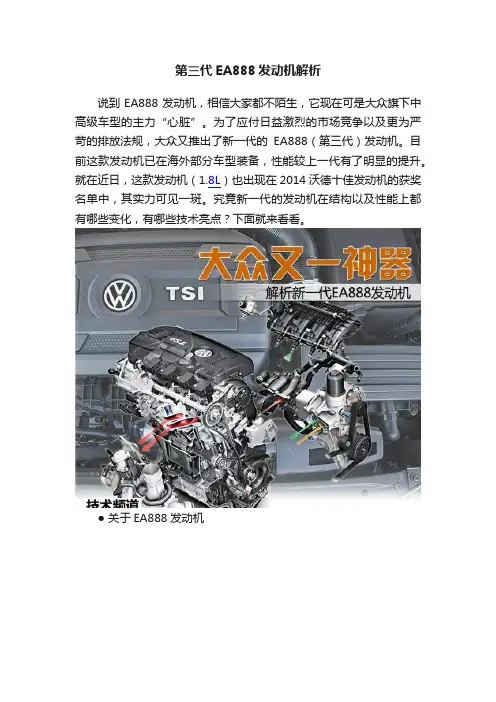
第三代EA888发动机解析说到EA888发动机,相信大家都不陌生,它现在可是大众旗下中高级车型的主力“心脏”。
为了应付日益激烈的市场竞争以及更为严苛的排放法规,大众又推出了新一代的EA888(第三代)发动机。
目前这款发动机已在海外部分车型装备,性能较上一代有了明显的提升。
就在近日,这款发动机(1.8L)也出现在2014沃德十佳发动机的获奖名单中,其实力可见一斑。
究竟新一代的发动机在结构以及性能上都有哪些变化,有哪些技术亮点?下面就来看看。
● 关于EA888发动机EA888发动机绝对是大众汽车的明星发动机,目前已广泛应用于大众、奥迪等品牌下的多个车型上。
从图中可以看到,这款EA888发动机的历史并不算长,从2006年最早的第一代开始,到今年也才7年的光景,不过已经发展到了第三代。
汽车采用模块化平台生产已是大势所趋,作为新一代的EA888发动机,同样适合应用在大众最新的MQB和MLB平台上。
而符合欧6的排放标准,未来新一代EA888发动机也将成为大众中高级车型动力的“中流砥柱”。
这款第三代EA888发动机已在海外量产,并已搭载在部分新车型上,如新一代高尔夫Gti、2014款Jetta、Passat等。
目前国内的车型搭载的还是第二代EA888发动机,不过据了解目前大众长春发动机工厂也开始投产第三代EA888发动机了,看来这款全新的发动机很快就会来到我们的身边,而离我们最近的应该就是采用全新MQB模块化平台的国产奥迪A3了。
● 新三代EA888发动机性能提升了多少?从图中可以看到,第三代EA888发动机(1.8T)的动力性能明显要由于上代,最大扭矩达到了320N.m,而且在1400转时就已爆发,性能已直逼第二代2.0T版本。
同时可以看到(上图右侧曲线图),在保持发动机1500转的情况下,第三代EA888在不到3秒的时间内就已达到了峰值扭矩,动力响应时间比上代两个排量版本的都要好。
目前这款发动机在国外已经实现量产,已搭载在部分车型上,逐渐进行更新换代。
大众汽车集团——不同品牌的同款发动机(23年)大众旗下有众多汽车品牌,包括大众、奥迪、斯柯达、捷达、保时捷、兰博基尼、宾利等。
很多不同品牌的车型便搭载了同一款发动机,总结如下:发动机型号:DCB(3.0T),使用品牌:大众、奥迪使用车型:大众:途锐 2023款3.0TSI奥迪:Q7 2023款55TFSI;Q8 2023款55TFSI发动机型号:DHU(4.0T),使用品牌:奥迪、兰博基尼使用车型:奥迪:RSQ8兰博基尼:Urus兰博基尼Urus发动机型号:DJS(1.4T),使用品牌:斯柯达、大众、奥迪使用车型:斯柯达:明锐 2023款TSI280大众:帕萨特2023款280TSI;探影2021款280TSI;途铠2023款280TSI;探岳2023款280TSI;途观L 2023款280TSI;途安L 2021款奥迪:A3 2023款35TFSI奥迪发动机型号:DKX(2.0T),使用品牌:斯柯达、大众使用车型:斯柯达:柯迪亚克 2023款TSI380;柯迪亚克GT 2023款TSI380 大众:帕萨特2023款380TSI;大众CC 2023款380TSI;探岳X 2023款380TSI;途观L 2023款380TSI;途观X 2023款380TSI;途昂 2023款380TSI;途昂X 2023款380TSI;威然 2023款380TSI 发动机型号:DLE(1.4T),使用品牌:斯柯达、捷达、大众、奥迪使用车型:斯柯达:速派 2023款TSI280;明锐 2023款TSI28;捷达:VS5 2023款;VS7 2023款大众:高尔夫2023款280TSI;凌渡2023款;帕萨特2023款280TSI;迈腾 2023款 280TSI奥迪:A3 2023款35TFSI斯柯达发动机型号:DLF(1.5L),使用品牌:斯柯达、捷达、大众使用车型:斯柯达:昕锐 2022款;柯米克 2023款;柯米克GT 2023款捷达:VA3大众:桑塔纳 2021款大众汽车发动机型号:DME(2.5T),使用品牌:大众、奥迪使用车型:大众:途昂 2023款530V6;途昂X 2023款530V6;揽境 2023款530TSI奥迪:Q6 2023款50TFSI发动机型号:DMT(2.0T),使用品牌:奥迪、保时捷使用车型:奥迪:A4(进口) 2023款ALLROAD;A5 2023款45TFSI;A6进口;A7 2023款45TFSI;Q8 2023款45TFSI保时捷:Macan 2023款2.0T保时捷发动机型号:DPL(2.0T),使用品牌:斯柯达、大众使用车型:斯柯达:柯迪亚克 2023款TSI330;柯迪亚克GT 2023款TSI330 大众:帕萨特 2023款330TSI;大众CC 2023款330TSI;途观L 2023款330TSI;途观X 2023款330TSI;途昂 2023款330TSI;途昂X 2023款330TSI;威然 2023款330TSI发动机型号:DSV(1.5T),使用品牌:大众、奥迪使用车型:大众:宝来2023款300TSI;朗逸2023款300TSI;速腾2023款300TSI;途铠 2023款300TSI;探歌 2023款300TSI;途岳 2023款300TSI;探岳 2023款300TSI;途观L 2023款300TSI 奥迪:Q2L 2023款35TFSI;Q3 2024款35TFSI;Q3Sportback 2024款35TFSI发动机型号:DTH(2.0T),使用品牌:斯柯达、大众、奥迪使用车型:斯柯达:速派 2023款TSI330;柯迪亚克 2023款TSI330;柯迪亚克GT 2023款TSI330大众:帕萨特 2023款330TSI;迈腾 2023款330TSI;途岳 2023款330TSI;探岳2023款330TSI;探岳X 2023款330TSI;途观L 2023款330TSI;途观X 2023款330TSI;揽巡 2023款330TSI;途昂 2023款330TSI;途昂X 2023款330TSI;揽境 2023款330TSI;威然 2023款330TSI奥迪:Q3 2024款40TFSI;奥迪Q3Sportback 2024款40TFSI 发动机型号:DTJ(2.0T),使用品牌:斯柯达、大众、奥迪使用车型:斯柯达:柯迪亚克 2023款TSI380;柯迪亚克GT 2023款TSI380 大众:高尔夫2023款380TSI;帕萨特2023款380TSI;迈腾2023款380TSI;探岳 2023款380TSI;探岳X 2023款380TSI;途观L 2023款380TSI;途观X 2023款380TSI;揽巡 2023款380TSI;途昂 2023款380TSI;途昂X 2023款380TSI;揽境 2023款380TSI;威然 2023款380TSI奥迪:奥迪Q3 2024款45TFSI;奥迪Q3Sportback 2024款45TFSI发动机型号:DUT(1.4T),使用品牌:斯柯达、大众使用车型:斯柯达:柯珞克 2023款大众:探歌 2023款280TSI捷达发动机型号:DUV(2.0T),使用品牌:大众、奥迪使用车型:大众:途锐 2023款2.0TSI奥迪:Q7 2023款45TFSI。
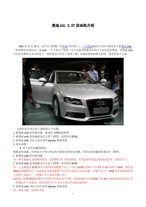
奥迪A4L 2.0T发动机介绍2008年11月16日,这个日子距离广州车展只有两天了,一汽奥迪如约正式在中国发布了新奥迪A4L,一时间网友争相讨论,新A4L一下子成为了明星。
关于这款车的基本介绍已不必在这里赘述,对奥迪A4L 已经有足够的文章介绍过了,相信您也已经有了基本了解,如果您想查阅相关资料,请查看如下文章:这些讨论中包含如下最热的几个话题:1 新奥迪A4L的价格问题,特别是2.0TSI标准型。
2 新奥迪A4L的变速箱为什么用了CVT,而没有用DSG。
3 新奥迪A4L为什么没全系用Quattro四驱系统。
4 加长问题。
● 对于常见问题的解答:根据这些问题,作者综合了网上网友的大量评论和技术讲解,对有这些问题的答案进行了整理:1 新奥迪A4L的价格问题。
答:网友普遍认为的确很便宜,比预期的33万的价格低。
但是价格毕竟是奥迪的家务事,谁也管不了。
2 新奥迪A4L的变速箱为什么用了CVT,而没有用DSG。
答:大众集团的DSG现在只能用在前横置平台上,所以AUDI品牌里只有TT和A3用到了DSG,他们是GOLF的横置平台。
具体原因可能是纵置平台的动力输出方向的问题。
好像只有日产GTR是在前纵置车型上用到了双离合。
(感谢汽车之家网友猫主席)。
编者按:纵置+DSG的现在不可能不代表未来不可能,奥迪纵置平台的DSG只在06年底的底特律车展上的一款概念车上出现过,但是到量产车上肯定不是这代A4能做到的。
3 新奥迪A4L为什么没全系用Quattro四驱系统。
答:成本问题,没啥好说的。
4 加长问题。
答:适应国内需求,国内消费者对内部空间的要求比较大,加长轴距能够最直接的获得充裕的车内空间。
●一篇文章激起千层浪在网友热议的问题中,也有不少网友在关心新款奥迪A4L会不会烧机油的问题,这是因为奥迪A6L 2.0TSI就存在普遍的烧机油现象,而新奥迪A4L如果使用和A6L 同样的2.0TSI发动机,就很有可能仍然有这个问题。
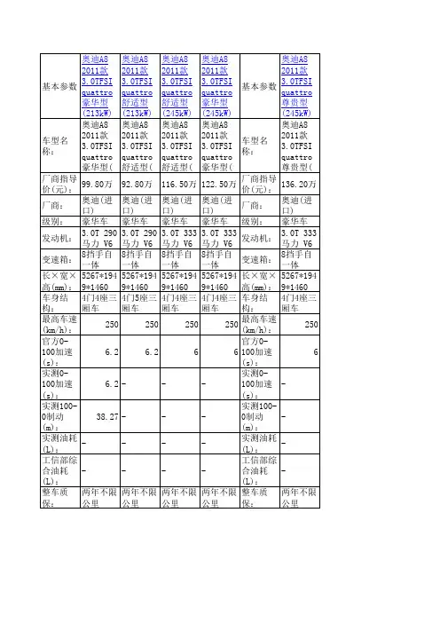
奥迪A8 4.28气缸发动机的澎湃动力和卓越品质再一次确立了奥迪A8在运动型豪华轿车领域的最高地位。
正是这款具有顶尖科技的TDI发动机,再一次向世人证明了奥迪公司在开发动力强劲、工艺精湛、经济节能的柴油发动机领域具有的无可比拟的领先技术及领导地位。
给人留下深刻印象的204KW的动力输出——全新奥迪A8 4.2 TDI quattro再次使奥迪在柴油轿车方面取得了领先。
这个全新开发动力强劲的4.2L八缸涡流增压柴油发动机配上A8的轻型全铝车身,使该车从0到100 公里加速仅为5.9秒,最高时速达到250km/h(电子限速)。
使此款全新发动机也在柴油发动机中树立了最高标准。
全新设计的发动机新奥迪A8 4.2 TDI的前身A8 4.0 TDI早已凭借其4升8缸发动机在豪华柴油轿车市场创下骄人战绩。
A8 4.0 TDI发动机功率达到275马力,扭矩为650牛·米,自2003年夏季上市以来便成为最强劲的V8柴油轿车。
百公里9.6升的油耗也令其在众多的竞争对手中脱颖而出,无可匹敌。
这些优异的性能保证了A8 4.0 TDI以71%的市场占有率在欧洲V8豪华型柴油车市场上稳占龙头地位。
根据统计结果制定的新款TDI发动机开发再次向新的目标发出挑战:奥迪公司力求它成为市场上前所未有的最强劲的轿车用柴油发动机,同时拥有最强的动力和极低的油耗,还要保证优化的发动机噪声控制、足够轻的重量以及紧凑简洁的设计。
为了实现这些目标,奥迪TDI开发小组设计了一款全新的发动机。
正如在此之前的3.0 和2.7TDI一样,拥有链传动凸轮轴及辅助设备的4.2升V8 TDI发动机开创了奥迪V型发动机家族的又一新系列。
气缸在发动机体内所占的空间为90毫米,整个发动机结构紧凑,总长仅为520毫米。
发动机气缸体采用GGV铸铁制造,仅重62公斤,使发动机总重降低到255公斤,比4.0 TDI 发动机还要轻15公斤。
4.2 TDI因此成为最轻的V8系列柴油轿车之一,这一点同时得益于为新奥迪A8 4.2 TDI quattro带来强劲动力的两大核心因素——动力重量比和均衡的质量分布。
1.6-litre R4 FSI engineOil circuitControlled Duocentric oil pumpA closed-loop Duocentric oil pump is employed. It maintains a near-constant oil pressure over the entire RPM range. Oil pressure is regulated by the control spring and control ring integrated in the oil pump.HousingExternal rotor Input shaft with internal rotorHousing coverDrive gearControl ringControl spring Oil intake manifold327_065CrankshaftDuocentric oil pump driveThe oil pump is driven by the crankshaft via a separate timing chain. The chain is tensioned by a mechanical chain tensioner.Drive chainReference For a functional description of the Duocentric oil pump, please refer to SSP 296 The 1.4-litre and 1.6-litre FSI engines with camshaft timing chain.Mechanical chain tensioner327_066 Oil pump drive gear141.6-litre R4 FSI engineOil circuitControlled Duocentric oil pumpA closed-loop Duocentric oil pump is employed. It maintains a near-constant oil pressure over the entire RPM range. Oil pressure is regulated by the control spring and control ring integrated in the oil pump.HousingExternal rotor Input shaft with internal rotorHousing coverDrive gearControl ringControl spring Oil intake manifold327_065CrankshaftDuocentric oil pump driveThe oil pump is driven by the crankshaft via a separate timing chain. The chain is tensioned by a mechanical chain tensioner.Drive chainReference For a functional description of the Duocentric oil pump, please refer to SSP 296 The 1.4-litre and 1.6-litre FSI engines with camshaft timing chain.Mechanical chain tensioner327_066 Oil pump drive gear14Cooling systemCoolant circuitThe cooling system has two circuits - one for cooling the cylinder block and one for cooling the cylinder head. One third coolant flows into the cylinder block and two thirds into the cylinder head. Coolant flow is regulated by two thermocouples integrated in the coolant thermostat housing. Whereas the short thermocouple probe for the coolant thermostat regulates coolant flow in the cylinder block, the long thermocouple probe for coolant thermostat regulates coolant flow in the cylinder head. Both thermocouples are closed up to a coolant temperature of approx. 87 °C, thus allowing the engine to reach operating temperature more quickly. The long thermocouple probe for the coolant thermostat is open at coolant temperatures from approx. 87 °C to 105 °C and the coolant temperature in the cylinder head is kept at approx. 87 °C. The temperature in the cylinder block can continue to rise. Both thermocouples are opened when the coolant temperature exceeds 105 °C, whereby the temperature is kept at 87 °C in the cylinder head and 105 °C in the cylinder block.Expansion tankEGR valveLong thermocouple probe for coolant thermostatHeater heat exchangerCoolant pumpCoolant circuit Cylinder blockCoolant circuit Cylinder headEngine oil cooler327_067Cooler Short thermocouple probe for coolant thermostatCoolant thermostat housing151.6-litre R4 FSI engineFuel systemSupply on demand fuel systemThe fuel system comprises a low-pressure circuit and a high-pressure circuit. The delivery rate of the electrical fuel pump G6 in the low-pressure circuit is regulated by the fuel pump control unit J538 so that only as much fuel as is necessary is delivered. This reduces the power consumption of the fuel pump and allows the fuel pressure to be increased in critical engine operating conditions involving possible vapour bubble formation. The electrical fuel pump is energised by the onboard power supply control unit when the driver's door is opened, thus resulting in the buildup of fuel pressure. After the engine is started, voltage is fed via the engine electronics control unit.Door contact switchBatteryLow-pressure circuitThe low-pressure circuit consists of – – – – the fuel tank, the fuel pump G6, the fuel filter, the fuel pressure sender, low pressure G410 and – the fuel pump control unit J538.Fuel pump control unit J538Fuel filterElectrical fuel pump G6Fuel tankPressureless Pressure 4 – 5 bar Pressure 50 – 100 bar16High-pressure circuitThe high-pressure circuit consists of – – – – – – the high-pressure fuel injection pump, the fuel pressure regulating valve, the high-pressure fuel rail, the high-pressure fuel pressure sender G247, the high-pressure fuel lines and the high-pressure injectors.Onboard power supply control unit J519Engine control unit J623High-pressure fuel pressure sender G247Fuel pressure sender, low pressure G410High-pressure fuel injection pump327_068High-pressure fuel railHigh-pressure injectors173.2-litre V6 FSI engineDescriptionTechnical features– Timing gear with chain – Timing chain on the transmission side – Continuously variable valve timing – Counter-rotating balancer shaft running at engine speed to compensate for crankshaft vibrations – Twin-path intake manifold made of plastic – Petrol direct injection with supply on demand fuel system – Siemens engine management system – Dual-circuit cooling system – Oil circuit with Duocentric oil pump and cold start valve327_002Reference For further information, please refer to SSP 325, AUDI A6 ‘05 - Ancillaries.18Performance featuresEngine code, torque and power outputThe engine code and engine number can be found on the front left-hand side of the cylinder block.327_008Torque/power curve440220Max. torque in Nm Max. power output in kWNmkW36014032010028060240 0 2000 4000 6000 800020Engine speed in RPMSpecificationsEngine code Type of engine Displacement in cm3AUK 6-cylinder vee-engine with 90° included angle 3123 188 (255) at 6500 RPM 330 at 3250 RPM 4 84.5 92.8 12.5 : 1 1–4–3–6–2–5 Unleaded Super, 95 RON (unleaded regular-grade, 91 RON, as an alternative with slight reduction in performance) Closed-loop catalytic converter with lambda control, NOx storage catalytic converter Siemens engine management system EU IVMax. power output in kW (bhp) Max. torque in Nm Number of valves per cylinder Bore in mm Stroke in mm Compression ratio Firing order Fuel gradeExhaust emission controlEngine management Exhaust emission standard193.2-litre V6 FSI engineChain driveDriven camshaft, oil pump and balancer shaftA flywheel-side chain drive was selected for the 3.2-litre V6 engine, as it is subject to less load than a front-side chain drive. The chain drive consists of sprockets A, B and C. The four camshafts are driven by the crankshaft by pinions A, B and C using a single-bush chain with two intermediate shafts. The required reduction ratio between the crankshaft and the camshaft is provided by the intermediate shaft. Hydraulic chain tensioners with built-in non-return valves are used for tensioning the chains. Oil is supplied via a separate riser.Pinion C Pinion BPinion APinion D327_010Note When removing and installing the balancer shaft and oil pump sprockets, attention must be paid to correct installation position as per the workshop manual.Oil pump drivePinion D drives the oil pump and the balancer shaft via a single roller chain. The chain drive is configured in such a way that the direction of rotation of the oil pump and the balancer shaft are reversed. The reduction ratio (i = 0.86) required for adapting the rotational speed of the oil pump is achieved by using different sprocket wheels.20Continuously variable valve timingContinuous adjustment of the intake and exhaust camshafts is provided by hydraulic swivel motors. The adjustment range for intake and exhaust camshafts is 42° in the "advance" direction. The adjusters are locked mechanically until the start of adjustment (once the required oil pressure has been reached). The Simos control unit (J361) controls the adjustment process via intake camshaft timing adjustment valve -1- (N205), intake camshaft timing adjustment valve -2- (N208), exhaust camshaft timing adjustment valve -1- (N318) and exhaust camshaft timing adjustment valve -2- (N319). Hall sender G40 (cylinder bank 1) and hall sender 2 G163 (cylinder bank 2) supply the signals required to locate the position of the intake camshafts, while hall sender 3 G300 (cylinder bank 1) and hall sender 4 G301 (cylinder bank 2) supply the signals required to locate the position of the exhaust camshafts.Hall sender G40 Exhaust camshaft timing adjustment valve -1- (N318)Intake camshaft timing adjustment valve -1- (N205)Hall sender 3 G300Intake camshaftExhaust camshaft327_020Variable valve timing adaptation A distinction is made between basic adaptation and fine adaptation. Basic adaptation After the engine is started, the camshafts remain in the starting position until their exact position has been determined in relation to the crankshaft. The values are stored in the Simos control unit. Basic adaptation is carried out when the voltage supply for the Simos control unit is disconnected or the fault memory is erased. Fine adaptation Fine adaptation is carried out after the engine is started if the camshafts are in the basic position and the coolant temperature is higher than 85 °C.213.2-litre V6 FSI engineBalancer shaftIn V6 engines with a cylinder angle of 90°, free inertial forces will cause the engine to run unevenly. A balancer shaft provides the necessary balancing of masses. The 3.2-litre V6 FSI engine therefore has a balancer shaft which is driven by the crankshaft via chain drive D. The timing chain is configured in such a way that the balancer shaft rotates in the reverse direction, thus allowing the inertial forces produced by the balancer shaft to counteract the first-order free inertial forces.Balancer shaftSplit conrod journalCrankshaft 327_01122Intake manifold upper sectionThrottle valve control unit J338Integrated vacuum reservoir327_013Stacked-plate oil coolerDuocentric oil pump Return-flow channelRiser 1Riser 2Main oil gallery Oil filter moduleOil pump drive327_043Bank 1Balancer shaft driveCrankshaft driveBank 2Central chain drive - pinion gear ASecond chain drive - pinion gear DCounterweightsBalancer shaft driveOil pump drive327_033Intake manifoldElectrical swirl flap adjusterSwirl flapsThrottle valve positionerExhaust gas recirculation currentIntake airCatalytic converter temperature sensor I Turbocharger control unitGuide vane adjustment327_034327_091Chain drive CChain drive BChain drive ACoolant pumpGear moduleIntake manifoldoutletOil return pipeto radiatorCylinder bank 2Cylinder bank 1Coolant distributor railAir inletTurbochargerPressure equaliser tubeSwirl flap adjusterSwirl flap frameSwirl flaps openSwirl flaps closedFuel filterRail elementCylinder bank 2 Rail elementCylinder bank 1ArmatureInjectorsCoolant outlet Oil inlet327_056327_005Chain drive C Chain drive BChain drive APower steering pumpChain drive D Coolant pump327_090Differential pressure boltInlet retard positionfrom inlet camshaft timing adjustment valveworking chamberInlet advance positionStatorCamshaft sprocketWorking chamber BPerformance featuresTorque and power outputThe engine code is located at the front on the cylinder block, below the left-hand cylinder head.A Z C .. .AZC...327_077Torque/power curve600 300Max. torque in Nm500 250Max. power output in kW400 Nm 300 200 kW 1502001001005001000300050007000Engine speed in RPMSpecificationsEngine code Type of engine Displacement in cm3AZC 12-cylinder W-engine 5998 331 (450) at 6200 RPM 580 from 4000 to 4700 RPM 4 84 90.2 10.75 : 1 1–12–5–8–3–10–6–7–2–11–4–9 Super Plus unleaded, Euro-Super, 98/95 RON Closed-loop catalytic converter with 8 lambda probes, air-gap insulated exhaust manifold/ catalytic converter modules Bosch Motronic ME 7.1.1 EU IVMax. power output in kW (bhp) Max. torque in Nm Number of valves per cylinder Bore in mm Stroke in mm Compression ratio Firing order Fuel grade Exhaust emission controlEngine management Exhaust emission standard536.0-litre W12 engineChain driveCamshaft driveThe timing chains are located on the flywheel side of the engine. The camshaft is driven by a simplex (single-link) chain (primary chain) running from the crankshaft to the intermediate shaft, which connects to a further two simplex chains (secondary chains) running to cylinder banks 1 and 2. The required reduction ratio from the crankshaft to the camshaft is provided by the different diameters of the sprockets. The timing chain is tensioned by hydraulic chain tensioners.Cylinder bank 2 Chain tensioner Cylinder bank 2Cylinder bank 1Slide railSlide railIntermediate shaft chain sprocketChain tensioner Cylinder bank 1Chain tensioner, primary chain Slide rail327_078 Crankshaft chain sprocket54Continuously variable valve timingThe four vane cell adjusters for exhaust and intake camshaft adjustment are supplied with pressurised oil via the engine oil circuit.Camshaft adjuster Exhaust camshaft Camshaft adjuster Intake camshaft Retard Camshaft adjuster Intake camshaft Advance E E Advance RetardCamshaft adjuster Exhaust camshaftRetardAdvance Advance A A Retard327_079 Cylinder bank 2 A – adjustment range, exhaust 11° (22° crank angle) E – adjustment range, intake 26° (52° crank angle) Cylinder bank 1Coil springCamshaft adjuster with springThe oil circuit has been optimised to ensure proper lubrication of the low-friction bearings under all operating conditions. However, an insufficient supply of oil to the camshaft adjusters can occur when the engine is hot-idling. To ensure sufficient oil pressure is available in order to advance the exhaust camshaft timing, an auxiliary coil spring resting on the adjuster housing helps to turn the internal rotor in the "advance" direction.327_096556.0-litre W12 engineCooling systemCoolant circuitThe coolant pump delivers coolant to the two cylinder banks, where the coolant flow is divided into two partial flows passing through the cylinder banks and cylinder heads. The coolant then enters the coolant reservoir in the inner vee of the engine, from where it flows to the cooler (primary coolant circuit) or the coolant thermostat and the coolant pump (secondary coolant circuit). Some of the coolant is tapped from the return line from cylinder bank 1 to cool the alternator and from the return line from cylinder bank 2 to supply the heat exchanger.Expansion tankVent pipeTemperature sender F18Coolant temperature sender G2/G62Non-return valve 2Continued coolant circulation pump V51Coolant thermostatVent screwsATF coolerHeat regulation valve N175/N176Heat exchangerCoolant reservoir327_08056Oil circuitWet-sump lubrication systemThe oil circuit in the Audi 6.0-litre W12 engine is designed as a wet-sump lubrication system. The oil filter and the oil cooler module are attached to the crankcase. The mounting bracket for the water-cooled alternator is located on the oil cooler module. The main bearings are supplied through an overhead oilway in the vee of the engine. The camshaft timing chains (secondarychains) have oil injection ports in the chain tensioner rails for lubrication and cooling. The contact surfaces on the primary chain are lubricated by the oil which flows back from the cylinder heads into the chain housing and through oil injection ports in the secondary chains.Oil retention valve Camshafts Bank 1Riser with oil retention valve Camshafts Bank 2 to intermediate shaftto chain tensionerCentral oil portRiserOil return pipeOil return pipe Piston injectors with oil pressure release valves Crankcase breather Return line Supply line Oil inlet from oil sump Main bearingMain oil port327_083Cyclone fine separatorBlow-by gases to intake manifoldPressure control valveOil separatorMounted on the intake manifolds are separator modules which remove oil particles from the blow-by gases. For this purpose, the blow-by gases are channeled to the oil separator through coarseparticle separators integrated in the cylinder heads and lines. A large proportion of the oil is separated at the inlet to the oil separator by baffle plate separators. Three cyclone fine separators operating in parallel separate the existing ultra-fine oil droplets and channel the blow-by gases through a pressure control valve into the cylinder bank intake manifolds. The separated oil collects in the bottom part of the separator and returns directly to the cylinder heads.Oil return pipe Ribs as coarse-particle preseparator 327_095576.0-litre W12 engineExhaust systemExhaust manifoldThe four 3-in-1 manifolds, the two headpipes and the four close-coupled catalytic converters have been combined to create four manifold/catalytic converter modules. Dispensing with a flanged connection between the headpipe and the manifold offers the following advantages: – enhanced inflow to the close-coupled catalytic converters – no flange-related heat loss – better pipe layout – reduced weightManifold/catalytic converter module 1Manifold/catalytic converter module 2327_098Inner exhaust gas recirculationNitrogen oxides are reduced by the internal exhaust gas recirculation system. The proportion of exhaust gas recirculated is defined by the intake and exhaust camshaft adjustments.327_08258。
奥迪汽车发动机型号及排量一览表(2015)
品牌型号出厂排量发动机型号排量发动机型号排量发动机型号排量发动机型号排量发动机型号
奥迪
A3国产 1.4T EA211 1.8T EA888
A4L国产 1.8T—— 2.0T EA888 3.0L机械增压
A6L国产 2.0T EA888 2.5L自然吸气 2.8L自然吸气 3.0L机械增压
Q3国产 1.4T—— 2.0T EA888
Q5国产 2.0T EA888
A1进口 1.4T——
A3进口 1.4T—— 1.8T EA888
S3进口 2.0T EA888
A4进口 2.0T EA888
A5进口 2.0T EA888 3.0L机械增压
S5进口 3.0T——
A6进口 3.0L机械增压 2.0T R-4 TFSI
S6进口 4.0T CEU
A7进口 2.0T EA888 3.0L机械增压 2.5L自然吸气 2.8L自然吸气
S7进口 4.0T CEU
A8进口 2.0T R-4 TFSI 2.5L自然吸气 3.0L机械增压 4.0L机械增压 6.3L自然吸气Q3进口 2.0T——
Q5进口 2.0T—— 3.0T——
SQ5进口 3.0T CTX
Q7进口 3.0L机械增压 3.0T——
TT进口 2.0T——
TTS进口 2.0T EA113
R8进口 4.2L自然吸气 5.2L自然吸气
RS5进口 4.2L自然吸气
RS7进口 4.0T CEU—— 为未知发动机型号。
大众奥迪系列3.0T机械增压发动机至今发展到第四代,本文对第四代3.0L升V6TSI发动机—EA837进行技术层面解析,希望对广大维修同行有所帮助。
由于篇幅较长,文本将会分为多篇和大家进行分享。
感兴趣的同行朋友们敬请关注后续文章更新。
第四代3.0L升V6TSI发动机—EA837技术解析一、技术概要●发动机结构●润滑系统●空气供给和我机械增压●冷却系统●燃油系统●发动机管理系统●维修保养注意事项第四代3.0L升V6TSI发动机—EA837最重要的特征如下:符合EU6排放标准v型6缸发动机,带电磁离合器控制的皮带驱动式机械增压器供油系统结合了直喷和进气歧管喷射两种喷射模式,排放和油耗水平更佳进气和排气侧凸轮轴持续调节1.1 第三代3.0L-V6-TSI发动机具备优良的外输出特性和出色的瞬时响应特性,第四代发动机进行升级的目的是在保持原有特性的同时,显著降低油耗和排放。
这是通过一下主要措施实现的:降低发动机的摩擦,优化链条传动机构通过降低预应力优化活塞环套件,同时改善了机油消耗,降低凸轮轴轴承的摩擦力;通过引入电磁离合器,实现了针对机械式增压系统的”按需增压”;高度灵活的喷油策略,可允许高压喷射和低压喷射混合运行;燃烧过程的组件进行了进一步优化。
1.2 相较于第三代3.0L-V6-TSI发动机有以下具体的改进:采用中空钻孔曲轴销的曲轴,嵌入式灰口铸铁气缸套,活塞形状改变;采用了可控式机械增压器(罗芡增压器);增加了进气歧管喷射;增加了排气侧凸轮轴调节;將发动机机油冷却器(可控式),移到发动机背面,油底壳和后部发动机盖(密封法兰)进行了调整;链条传动进行了修改,链条更短更轻;仅一个气缸列上有曲轴箱排气;带改进型(可控式)泵轮的冷却液泵;采用Terophon涂层的正时链盖板;用于降低摩擦和重量的组合措施。
二、技术概要-技术数据1)也允许使用91号普通无铅汽油,但是功率会有所降低。
2.1扭矩-功率曲线待续,最新更新请留意奥德科技。