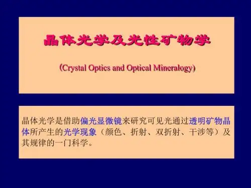
晶体光学 Crystal Optics Optical crystallography
- 格式:ppt
- 大小:17.19 MB
- 文档页数:2
晶体光学复习资料一、概念1.晶体光学:晶体光学是研究可见光通过透明晶体时所产生的一些光学现象及其原理的一门科学。
不同的透明矿物显示的光学性质不相同,据此可以鉴别透明矿物。
因此,晶体光学是研究、鉴定透明矿物及岩石的重要方法。
2.偏光作用在晶体光学中的应用:晶体光学研究中主要是应用偏光。
研究的主要仪器是偏光显微镜,其中装置有使自然光转变为偏光的偏光镜(起偏镜)。
偏光镜通常是根据选择吸收作用(偏光片)或双折射作用(尼科尔棱镜)产生偏光的原理制成的。
自然光通过偏光镜后即转变成振动方向固定的偏光。
3.均质体:根据光学性质不同,可以把透明物质划分为均质体和非均质体两大类。
等轴晶系矿物及非晶质物质的光学性质各个方向相同,称为光性均质体,简称均质体;如石榴石、萤石、火山玻璃及加拿大树胶等。
4.非均质体:根据光学性质不同,可以把透明物质划分为均质体和非均质体两大类。
中级晶族和低级晶族的矿物,其光学性质随方向而异,称为光性非均质体,简称非均质体,如石英、长石、橄榄石等。
绝大多数造岩矿物属于非均质体,是我们研究的重点。
5.光轴:实验证明,光波沿非均质体的特殊方向射入时不发生双折射,基本不改变入射光波的振动特点和振动方向。
非均质体中,这种不发生双折射的特殊方向称为光轴(optic axis)。
中级晶族晶体只有一个光轴方向,称为一轴晶;低级晶族晶体有两个光轴方向,称为二轴晶。
6.一轴晶光率体中概念:中级晶族晶体的水平结晶轴轴单位相等,即a=b≠c。
水平方向上(垂直Z晶轴)的光学性质相同。
当光波的振动方向垂直Z晶轴时(即沿水平方向振动),相应的折射率值相等,此为常光的折射率值,以符号“No ”表示。
当光波的振动方向平行Z晶轴时,相应的折射率值与No相差最大,为非常光的折射率值,以符号“Ne”表示。
光波的振动方向与Z晶轴斜交时,相应的折射率值递变于No与Ne之间,亦为非常光的折射率,以符号“Ne'”表示。
Ne'值的大小随光波振动方向与Z晶轴的夹角大小而变化。
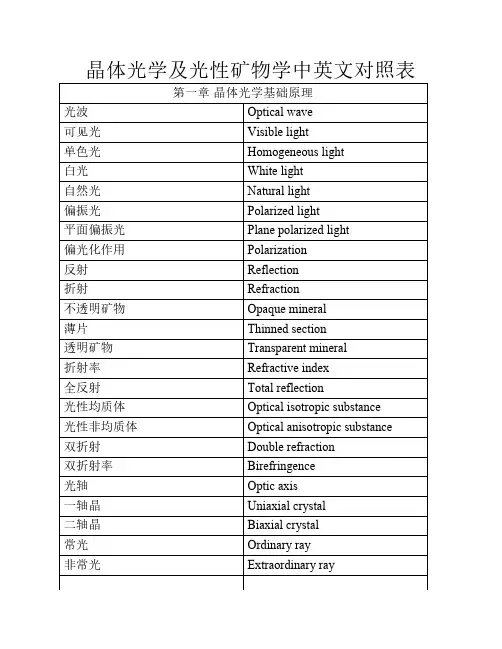
晶体光学及光性矿物学中英文对照表第一章晶体光学基础原理光波Optical wave可见光Visible light单色光Homogeneous light白光White light自然光Natural light偏振光Polarized light平面偏振光Plane polarized light偏光化作用Polarization反射Reflection折射Refraction不透明矿物Opaque mineral薄片Thinned section透明矿物Transparent mineral折射率Refractive index全反射Total reflection光性均质体Optical isotropic substance光性非均质体Optical anisotropic substance双折射Double refraction双折射率Birefringence光轴Optic axis一轴晶Uniaxial crystal二轴晶Biaxial crystal常光Ordinary ray非常光Extraordinary ray主折射率Principal refraction index最大双折射率Maximum birefringence光性指示体Indicatrix光率体Optic indicatrix主轴Principal axis主轴面Principal section园切面Circular section光性符号Optical sign主截面Principal section主折射率Principal refractive index光轴面Optic axial plane光轴角Optic axial angle锐角等分线Acute bisectrix钝角等分线Obtuse bisectrix光轴角公式Optic angle equation光性方位Optic orientation色散Dispersion折射率色散Refractive index dispersion色散曲线Dispersion curve双折射率色散Birefringence dispersion光率体色散Indicatrix dispersion第二章透明造岩矿物及宝石晶体光学鉴定常用仪器孔径N*A numerical aperture尼康NIKON奥林珀斯OLYMPUS第三章透明造岩矿物及宝石在单偏光镜下的晶体光学性质边缘Edge贝克线Becke line糙面Rough surface突起Relief突起等级Relief grade闪突起Twinkling解理Cleavage解理纹Trace of cleavage临界角Critical angle极完全解理Eminent cleavage完全解理Perfect cleavage不完全解理Imperfect cleavage颜色Colour多色性Pleochroism吸收性Absorption多色性公式Pleochroic formula吸收性公式Absorption formula正吸收Positive absorption反吸收Negative absorption 第四章透明造岩矿物及宝石在正交偏光镜下的晶体光学性质消光Extinction全消光Complete extinction消光位Extinction position光程差Path difference石英楔quartz wedge干涉色Interference color色序Color sequence级序Gradation sequence补色法则Compensation principle消色Subtractive color补色器Compensator试板Accessory plate云母试板Mica plate石膏试板Gypsum plate贝瑞克Berek倾斜消色器Tilting compensator谢纳蒙特Senarment布雷斯-科勒Brece-Kohler中村试板Nakamura half-shadow plate 莱特目镜Wright eyepiece消光类型Types of extinction平行消光Parallel extinction斜消光Inclined extinction对称消光Symmetrical extinction消光角Extinction angle延性Elongation正延性Positive elongation负延性Negative elongation延性符号Sign of elongation双晶Twin双晶面Twin plane双晶纹Trace of twin plane简单双晶Simple twin复式双晶Combined twin聚片双晶Polysynthetic twin轮式双晶Cyclic twin格子双晶Tartan twinning第五章透明造岩矿物及宝石在锥偏光镜下的晶体光学性质干涉图Interference figure勃氏镜Bertrand lens黑十字Dark cross干涉色圈Interference color circles波向图Skiodrome闪图Flash figure瞬变干涉图Transient axial figure马拉德Mallard托比Tobi第六章透明造岩矿物及宝石的晶体光学系统鉴定。

optical clarity 晶状体光学净度
光学净度是指透明材料对光的透过程度的度量,通常用于描述镜片、透镜等光学器件的质量。
光学净度越高,表示材料对光的衰减越少,光线透过材料时会更清晰。
晶状体是眼睛中的一部分,位于虹膜与视网膜之间,是负责聚焦光线的组织。
当晶状体出现问题时,会影响眼睛对光线的聚焦能力,导致视力模糊。
因此,光学净度和晶状体之间的关系是,光学净度高的透明材料可以使光线更清晰地穿过晶状体,从而提高眼睛对光的聚焦能力,保持良好的视力。

光学性质的光子晶体PhotonicCrystal美国科学家研发出了一种新方法,改变了半导体的三维结构,使其在保持电学特性的同时拥有了新的光学性质,并据此研制出了首块光学电学性能都很活跃的新型光子晶体(Photonic Crystal),为以后研制出新式太阳能电池、激光器、超材料等打开了大门。
研究发表在最新一期《自然·材料学》杂志上。
光子晶体(Photonic Crystal)材料具有独特的物理结构,它能采用不同于传统光学材料和设备的特殊方式诱发非同寻常的现象并影响光子的行为,可广泛应用于激光器、太阳能设备、超材料等中。
之前由科学家们研制出的光子晶体(Photonic Crystal)只能得到用光学方法激活的设备,这些设备能引导光,但无法被电所激活,因此,其无法将电变成光或相反。
伊利诺斯大学材料科学和工程学教授保罗·布劳恩领导的科研团队研制出的最新光子晶体(Photonic Crystal)却兼具光学和电学性质。
该研究的参与者埃里克·尼尔森解释道,新光子晶体(Photonic Crystal)可以让光学和电学性能同时达到最优化,这就使人们能更好地控制光的散射、吸收以及增强。
为了制造出该三维光子晶体(Photonic Crystal),科学家们先让一些细小的球簇拥在一起形成一块模板,接着,他们将一种广泛应用于半导体中的材料砷化镓(GaAs)沉积在模板上,让砷化镓通过模板填充球之间的缝隙。
砷化镓作为单个晶体开始从下往上生长,这个过程被称作外延生长技术,工业界一般使用该技术来制造平的、二维的单晶体半导体薄膜,但布劳恩团队却对这种技术进行了升级改造,用来制造错综复杂的三维结构。
这种自下而上的外延生长技术消除了制造三维光子结构普遍采用的自上而下构造方法可能导致的很多缺陷。
另一个好处是,它让制造出层层堆积而成的半导体异质结构变得更方便。
例如,可以通过先用砷化镓部分填充该模板,再用另一种材料填满,从而将一个量子势阱层引入光子晶体(Photonic Crystal)中。

晶体光学和光波导晶体光学和光波导是光学领域中重要的研究方向,它们在光通信、激光技术和光电子学等领域都有着广泛的应用。
本文将对晶体光学和光波导的基本原理、研究进展以及应用前景进行探讨。
一、晶体光学的基本原理及特性晶体光学研究的是晶体在光的作用下的行为和性质。
晶体是由周期性排列的原子或分子组成的固体,具有各向异性和周期性特征。
在晶体中,光的传播、吸收和散射都与晶体的晶格结构、折射率和振动模式等有关。
光的传播在晶体中受到折射、反射和吸收等影响,其中最重要的是折射现象。
晶体的折射率取决于光的入射角度和光的波长,不同的晶体结构和成分也会对折射率产生影响。
此外,晶体还具有双折射现象,即光根据偏振状态的不同而产生不同的折射效果。
晶体的光学性质与其晶格结构密切相关。
光与晶体中的原子或分子相互作用时,会激发晶体的振动模式,产生特定的光学谱线。
这些谱线可以提供有关晶体的结构和成分信息,对于研究晶体的光学性质具有重要意义。
二、光波导的原理及应用光波导是一种通过光的全内反射来传输光信号的器件。
它通常由具有较高折射率的芯层和较低折射率的包层构成。
当光沿着芯层传播时,由于芯层的折射率高于包层,光会发生全内反射,并沿芯层内部传输。
这样,光信号可以在波导中保持高度聚焦和传输,提供了高效的光通信和光电子学器件。
光波导具有多种类型,常见的有直波导、曲线波导和光纤波导等。
不同类型的光波导在光的传输方式和性能上有所差异,因此适用于不同的光学应用场景。
例如,直波导适用于短距离光传输和光耦合;曲线波导适用于制作光学器件和集成光电子学芯片;光纤波导适用于远距离光通信和信号传输。
光波导的应用非常广泛。
在光通信领域,光波导是高速、大带宽通信系统的重要组成部分,可以实现高速、低损耗的光信号传输。
此外,光波导还可用于制备光放大器、激光器和光传感器等器件,在生物医学和环境监测等领域有着广阔的应用前景。
三、晶体光学与光波导的结合应用晶体光学和光波导作为研究领域,各自具有独特的特点和应用前景。
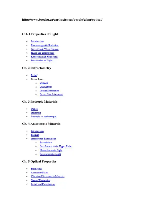
http://www.brocku.ca/earthsciences/people/gfinn/optical/CH. 1 Properties of Light∙Introduction∙Electromagnetic Radiation∙Wave Front, Wave Normal∙Phase and Interference∙Reflection and Refraction∙Polarization of LightCh. 2 Refractometry∙Relief∙Becke Lineo Definedo Lens Effecto Internal Reflectiono Becke Line MovementCh. 3 Isotropic Materials∙Optics∙Indicatrix∙Isotropic vs. AnisotropicCh. 4 Anisotropic Minerals∙Introduction∙Packing∙Interference Phenomenao Retardationo Interference at the Upper Polaro Monochromatic Lighto Polychromatic LightCh. 5 Optical Properties∙Extinction∙Accessory Plates∙Vibration Directions in Minerals∙Sign of Elongation∙Relief and PleochroismCh. 6 Uniaxial Minerals∙Uniaxial Optics∙Uniaxial Optic Sign∙Paths Followed by Light∙Uniaxial Indicatrix∙Birefringence and Interference Colours∙Extinction in Uniaxial Minerals∙Pleochroism in Uniaxial Minerals∙Interference figureso How to obtain an Interference Figureo Optic Axis Figure▪Interference Figure▪Formation of the Isochromes▪Formation of the Isogyres▪Optic Sign Determinationo Off-Centred Optic Axis Figureo Uniaxial Flash Figure∙Summary of Uniaxial Interference FiguresCh. 7 Biaxial Minerals∙Biaxial Optics∙Biaxial Indicatrix∙Optic Sign∙Crystallographic Orientation and the Indicatrix∙Biaxial Inteference Figureso Acute Bisectrix Figure (Bxa)▪Formation of the Isochromes▪Vibration Directions and Formation of the Isogyres▪Rotation of the Isogyreo Centred Optic Axis Figureo Obtuse Bisectrix Figure (Bxo)o Optic Normal or Biaxial Flash Figureo Off Centred Figures∙Optic sign determinationo Acute Bisectrix Figureo Obtuse Bisectrix Figureo Optic Axis Figureo Optic Normal∙Identifying Grains Which Will Produce Usable Interference Figures ∙Other Properties of Biaxial MineralsCh. 8 Other MineralsKnown Minerals - How to Describe Them?<<Optical Mineralogy>>Properties of Light1. INTRODUCTIONLight- a form of energy, detectable with the eye, which can be transmitted from one place to another at finite velocity.Visible light is a small portion of a continuous spectrum of radiation ranging from cosmic rays to radio waves.Fig. Light spectrumWhite or visible light, that which the eye detects, is only a fraction of the complete spectrum - produced by shining white light through a glass prism.Two complimentary theories have been proposed to explain how light behaves and the form by which it travels.1.Particle theory - release of a small amount of energy as a photon when an atom is excited.2.Wave theory - radiant energy travels as a wave from one point to another.Waves have electrical and magnetic properties => electromagnetic variations.Wave theory effectively describes the phenomena of polarization, reflection, refraction and interference, which form the basis for optical mineralogy.Fig. Components of a light ray2. ELECTROMAGNETIC RADIATIONThe electromagnetic radiation theory of light implies that light consists of electric and magnetic components which vibrate at right angles to the direction of propagation.In optical mineralogy only the electric component, referred to as the electric vector, is considered and is referred to as the vibration direction of the light ray.The vibration direction of the electric vector is perpendicular to the direction in which the light is propagating.The behaviour of light within minerals results from the interaction of the electric vector of the light ray with the electric character of the mineral, which is a reflection of the atoms and the chemical bonds within that minerals.Light waves are described in terms of velocity, frequency and wavelength.The velocity (V) and the wavelength are related in the following equation,where:F = Frequency or number of wave crests per second which pass a reference points =>cycles/second of Hertz (Hz).For the purposes of optical mineralogy, F = constant, regardless of the material through which the light travels. If velocity changes, then the wavelength must change to maintain constant F.Light does not consist of a single wave => infinite number of waves which travel together.3. WAVE FRONT, WAVE NORMALWith an infinite number of waves travelling together from a light source, we now define:1.Wave front - parallel surface connecting similaror equivalent points on adjacent waves.2.Wave Normal - a line perpendicular to the wavefront, representing the direction the waveis moving.3.Light Ray is the direction of propagation of the light energy.Minerals can be subdivided, based on the interaction of the light ray travelling through the mineral and the nature of the chemical bonds holding the mineral together, into two classes:a)Isotropic MineralsIsotropic materials show the same velocity of light in all directions because the chemical bonds holding the minerals together are the same in all directions, so light travels at the same velocity in all directions.Examples of isotropic material are volcanic glass and isometric minerals (cubic) Fluorite, Garnet, HaliteIn isotropic materials the Wave Normal and Light Ray are parallel.b)Anisotropic MineralsAnisotropic minerals have a different velocity for light, depending on the direction the light is travelling through the mineral. The chemical bonds holding the mineral together will differ depending on the direction the light ray travels through the mineral.a)Anisotropic minerals belong to tetragonal, hexagonal, orthorhombic, monoclinicand triclinic systems.In anisotropic minerals the Wave Normal and Light Ray are not parallel.Light waves travelling along the same path in the same plane will interfere with each other.4. PHASE AND INTERFERENCEBefore going on to examine how light inteacts with minerals we must define one term:RETARDATION - (delta) represents the distance that one ray lags behind another. Retardation is measured in nanometres, 1nm = 10-7cm, or the number of wavelengths by which a wave lags behind another light wave.The relationship between rays travelling along the same path and the interference between the rays is illustrated in the following three figures.1.If retardation is a whole number (i.e., 0, 1, 2, 3, etc.) of wavelengths.The two waves, A and B, are IN PHASE, and they constructively interfere with each other. The resultant wave (R) is the sum of wave A and B.2.When retardation is = ½, 1½, 2½ . . . wavelengths.The two waves are OUT OF PHASE they destructively interfere, cancelling each other out, producing the resultant wave (R), which has no amplitude or wavelength.3.If the retardation is an intermediate value, the the two waves will:1.be partially in phase, with the interference being partially constructive2.be partially out of phase, partially destructive.In a vacuum light travels at 3x1010 cm/sec (3x10¹⁷ nm/sec).When light travels through any other medium it is slowed down, to maintain constant frequency the wavelength of light in the new medium must also changed.5. REFLECTION AND REFRACTIONAt the interface between the two materials, e.g. air and water, light may be reflected at the interface or refracted (bent) into the new medium.For Reflection the angle of incidence = angle of reflection.For Refraction the light is bent when passing from one material to another, at an angle other than perpendicular.A measure of how effective a material is in bending light is called the Index of Refraction (n), where:Index of Refraction in Vacuum = 1 and for all other materials n > 1.0.Most minerals have n values in the range 1.4 to 2.0.A high Refractive Index indicates a low velocity for light travelling through that particular medium.Snell's LawSnell's law can be used to calculate how much the light will bend on travelling into the new medium.If the interface between the two materials represents the boundary between air (n ~ 1) and water (n = 1.33) and if angle of incidence = 45°, using Snell's Law the angle of refraction = 32°.The equation holds whether light travels from air to water, or water to air.In general, the light is refracted towards the normal to the boundary on entering the material with a higher refractive index and is refracted away from the normal on entering the material with lower refractive index.In labs, you will be examining refraction and actually determine the refractive index of various materials.6. POLARIZATION OF LIGHTAll of this introductory material on light and its behaviour brings us to the most critical aspect of optical mineralogy - that of Polarization of Light.Light emanating from some source, sun, or a light bulb, vibrates in all directions at right angles to the direction of propagation and is unpolarized.In optical mineralogy we need to produce light which vibrates in a single direction and we need to know the vibration direction of the light ray. These two requirements can be easily met but polarizing the light coming from the light source, by means of a polarizing filter.Three types of polarization are possible.1.Plane Polarization2.Circular Polarization3.Elliptical PolarizationFig. Three types of Polarized lightIn the petrographic microscope plane polarized light is used. For plane polarized light the electric vector of the light ray is allowed to vibrate in a single plane, producing a simple sine wave with a vibration direction lying in the plane of polarization - this is termed plane light or plane polarized light.Plane ploarized light may be produced by reflection, selective absorption, double refraction and scattering.1.ReflectionUnpolarized light strikes a smooth surface, such as a pane of glass, tabletop, and thereflected light is polarized such that its vibration direction is parallel to the reflecting surface.The reflected light is completely polarized only when the angle between the reflected and the refracted ray = 90°.2.Selective AbsorptionThis method is used to produce plane polarized light in microscopes, using polarized filters.Some anisotropic materials have the ability to strongly absorb light vibrating in onedirection and transmitting light vibrating at right angles more easily. The ability toselectively transmit and absorb light is termed pleochroism, seen in minerals such astourmaline, biotite, hornblende, (most amphiboles), some pyroxenes.Upon entering an anisotropic material, unpolarized light is split into two plane polarizedrays whose vibratioin directions are perpendicular to each other, with each ray havingabout half the total light energy.If anisotropic material is thick enough and strongly pleochroic, one ray is completelyabsorbed, the other ray passes through the material to emerge and retain its polarization.3.Double RefractionThis method of producing plane polarized light was employed prior to selective absorption in microscopes. The most common method used was the Nicol Prism. See page 14 and Figure 1.14 in Nesse.4.ScatteringPolarization by scattering, not relevant to optical mineralogy, is responsible for the blue colour of the sky and the colours observed at sunset.Ch.2 Refractometry1. RELIEFThis section is covered in Chapter 3 of Nesse.Refractometry involves the determination of the refractive index of minerals, using the immersion method. This method relys on having immersion oils of known refractive index and comparing the unknown mineral to the oil.If the indices of refraction on the oil and mineral are the same light passes through the oil-mineral boundary un-refracted and the mineral grains do not appear to stand out.If n oil <> n mineral then the light travelling though the oil-mineral boundary is refracted and the mineral grain appears to stand out.Fig. Relief - the degree to which a mineral grain or grains appear to stand out from the mounting material, whether it is an immersion oil, Canada balsam or another mineral.When examining minerals you can have:1.Strong reliefo mineral stands out strongly from the mounting medium,o whether the medium is oil, in grain mounts, or other minerals in thin section,o for strong relief the indices of the mineral and surrounding medium differ by greater than 0.12 RI units.2.Moderate reliefo mineral does not strongly stand out, but is still visible,o indices differ by 0.04 to 0.12 RI units.3.Low reliefo mineral does not stand out from the mounting medium,o indices differ by or are within 0.04 RI units of each other.A mineral may exhibit positive or negative relief:∙+ve relief - index of refraction for the material is greater than the index of the oil.- e.g. garnet 1.76∙-ve relief n min < n oil- e.g. fluorite 1.433It is useful to know whether the index of the mineral is higher or lower that the oil. This will be covered in the second lab section - Becke Line and Refractive Index Determination.2. BECKE LINEIn order to determine whether the idex of refraction of a mineral is greater than or less than the mounting material the Becke Line Method is used.Fig. Becke line - a band or rim of light visible along the grain boundary in plane light when the grain mount is slightly out of focus.Becke line may lie inside or outside the mineral grain depending on how the microscope is focused.To observe the Becke line:e medium or high power,2.close aperture diagram,3.for high power flip auxiliary condenser into place.Increasing the focus by lowering the stage, i.e. increase the distance between the sample and the objective, the Becke line appears to move into the material with the higher index of refraction.The Becke lines observed are interpreted to be produced as a result of the lens effect and/or internal reflection effect.LENS EFFECTMost mineral grains are thinner at their edges than in the middle, i.e. they have a lens shape and as such they act as a lens.If n min > n oil the grain acts as a converging lens, concentrating light at the centre of the grain.If n min < n oil, grain is a diverging lens, light concentrated in oil.INTERNAL REFLECTIONThis hypothesis to explain why Becke Lines form requires that grain edges be vertical, which in a normal thin section most grain edges are believed to be more or less vertical.With the converging light hitting the vertical grain boundary, the light is either refracted or internally reflected, depending on angles of incidence and indices of refraction.Result of refraction and internal reflection concentrates light into a thin band in the material of higher refractive index.If n min > n oil the band of light is concentrated within the grain.If n min < n oil the band of light is concentrated within the oil.BECKE LINE MOVEMENTThe direction of movement of the Becke Line is determined by lowering the stage with the Becke Line always moving into the material with the higher refractive index. The Becke Line can be considered to form from a cone of light that extends upwards from the edge of the mineral grain.Becke line can be considered to represent a cone of light propagating up from the edges of the mineral.If n min < n oil, the cone converges above the mineral.If n min > n oil, the cone diverges above the mineral.By changing focus the movement of the Becke line can be observed.If focus is sharp, such that the grain boundaries are clear the Becke line will coincide with the grain boundary.Increasing the distance between the sample and objective, i.e. lower stage, light at the top of the sample is in focus, the Becke line appears:∙in the mineral if n min >n oil∙or in the oil if n min << n oilBecke line will always move towards the material of higher RI upon lowering the stage.A series of three photographs showing a grain of orthoclase:1. The grain in focus, with the Becke line lying at the grain boundary.2. The stage is raised up, such that the grain boundary is out of focus, but the Becke line isvisible inside the grain.3. The stage is lowered, the grain boundary is out of focus, and the Becke line is visibleoutside the grain.When the RI of the mineral and the RI of the mounting material are equal, the Becke line splits into two lines, a blue line and an orange line. In order to see the Becke line the microscope is slightly out of focus, the grain appears fuzzy, and the two Becke lines are visible. The blue line lies outside the grain and the orange line lies inside the grain. As the stage is raised or lowered the two lines will shift through the grain boundary to lie inside and outside the grain, respectively.Index of Refraction in Thin SectionIt is not possible to get an accurate determination of the refractive index of a mineral in thin section, but the RI can be bracket the index for an unknown mineral by comparison or the unknown mineral with a mineral whose RI is known.Comparisons can be made with:1.epoxy or balsam, material (glue) which holds the sample to the slide n = 1.5402.Quartzo n w = 1.544o n e = 1.553Becke lines form at mineral-epoxy, mineral-mineral boundaries and are interpreted just as with grain mounts, they always move into higher RI material when the stage is lowered.Ch.3 Isotropic Materials1. OPTICSThis section is covered in Chapter 4 of Nesse.In Isotropic Materials - the velocity of light is the same in all directions. The chemical bonds holding the material together are the same in all directions, so that light passing through the material sees the same electronic environment in all directions regardless of the direction the light takes through the material.Isotropic materials of interest include the following isometric minerals: Halite - NaClIf an isometric mineral is deformed or strained then the chemical bonds holding the mineral together will be effected, some will be stretched, others will be compressed. The result is that the mineral may appear to be anisotropic.2. ISOTROPIC INDICATRIXTo examine how light travels through a mineral, either isotropic or anisotropic, an indicatrix is used.INDICATRIX - a 3 dimensional geometric figure on which the index of refraction for the mineral and the vibration direction for light travelling through the mineral are related.Isotropic IndicatrixIndicatrix is constructed such that the indices of refraction are plotted on lines from the origin that are parallel to the vibration directions.It is possible to determine the index of a refraction for a light wave of random orientation travelling in any direction through the indicatrix.1. a wave normal, is constructed through the centre of the indicatrix2. a slice through the indicatrix perpendicular to the wave normal is taken.3.the wave normal for isotropic minerals is parallel to the direction of propagation of lightray.4.index of refraction of this light ray is the radius of this slice that is parallel to the vibrationdirection of the light.For isotropic minerals the indicatrix is not needed to tell that the index of refraction is the same in all directions.Indicatrix introduced to prepare for its application with anisotropic materials.3. ISOTROPIC vs. ANISOTROPICDistinguishing between the two mineral groups with the microscope can be accomplished quickly by crossing the polars, with the following being obvious:1.All isotropic minerals will appear dark, and stay dark on rotation of the stage.2.Anisotropic minerals will allow some light to pass, and thus will be generally light, unlessin specific orientations.Why are isotropic materials dark?1.Isotropic minerals do no affect the polarization direction of the light which has passedthrough lower polarizer;2.Light which passes through the mineral is absorbed by the upper polar.Why do anisotropic minerals not appear dark and stay dark as the stage is rotated?1.Anisotropic minerals do affect the polarization of light passing through them, so somecomponent of the light is able to pass through the upper polar.2.Anisotropic minerals will appear dark or extinct every 90° of rotation of the microscopestage.3.Any grains which are extinct will become light again, under crossed polars as the stage isrotated slightly.To see the difference between Isotropic vs. Anisotriopic minerals viewed with the petrographic microscope look atthe following images:1.Image 1- plane light view of a metamorphic rock containing three garnet grains, in amatrix of biotite, muscovite, quartz and a large stauroite grain at the top of the image.2.Image 2- Crossed polar view of the same image. Note that the three garnet grains are'extinct" or black, while the remainnder of the minerals allow some light to pass.Ch. 4 Anisotropic MineralsINTRODUCTIONAnisotropic minerals are covered in Chapter 5 of Nesse.Anisotropic minerals differ from isotropic minerals because:1.the velocity of light varies depending on direction through the mineral;2.they show double refraction.When light enters an anisotropic mineral it is split into two rays of different velocity which vibrate at right angles to each other.In anisotropic minerals there are one or two directions, through the mineral, along which light behaves as though the mineral were isotropic. This direction or these directions are referred to as the optic axis.Hexagonal and tetragonal minerals have one optic axis and are optically UNIAXIAL.Orthorhombic, monoclinic and triclinic minerals have two optic axes and are optically BIAXIAL.In Lab # 3, you will examine double refraction in anisotropic minerals, using calcite rhombs.Calcite Rhomb Displaying Double RefractionLight travelling through the calcite rhomb is split into two rays which vibrate at right angles to each other. The two rays and the corresponding images produced by the two rays are apparent in the above image. The two rays are:1.Ordinary Ray, labelled omega w, n w = 1.6582.Extraordinary Ray, labelled epsilon e, n e = 1.486.Vibration Directions of the Two RaysThe vibration directions for the ordinary and extraordinary rays, the two rays which exit the calcite rhomb, can be determined using a piece of polarized film. The polarized film has a single vibration direction and as such only allows light, which has the same vibration direction as the filter, to pass through the filter to be detected by your eye.1.Preferred Vibration Direction NSWith the polaroid filter in this orientation only one row of dots is visible within the area of the calcite rhomb covered by the filter. This row of dots corresponds to the light ray which has a vibration direction parallel to the filter's preferred or permitted vibration direction and as such it passes through the filter. The other light ray represented by the other row of dots, clearly visible on the left, in the calcite rhomb is completely absorbed by the filter.2.Preferred Vibration Direction EWWith the polaroid filter in this orientation again only one row of dots is visible, within the area of the calcite coverd by the filter. This is the other row of dots thatn that observed in the previous image. The light corresponding to this row has a vibration direction parallel to the filter's preferred vibration direction.It is possible to measure the index of refraction for the two rays using the immersion oils, and one index will be higher than the other.1.The ray with the lower index is called the fast rayo recall that n = V vac/V mediumIf n Fast Ray = 1.486, then V Fast Ray = 2.02X10¹⁰ m/sec2.The ray with the higher index is the slow rayo If n Slow Ray = 1.658, then V Slow Ray = 1.8 1x10¹⁰ m/secRemember the difference between:∙vibration direction - side to side oscillation of the electric vector of the plane light and∙propagation direction - the direction light is travelling.Electromagnetic theory can be used to explain why light velocity varies with the direction it travels through an anisotropic mineral.1.Strength of chemical bonds and atom density are different in different directions foranisotropic minerals.2. A light ray will "see" a different electronic arrangement depending on the direction ittakes through the mineral.3.The electron clouds around each atom vibrate with different resonant frequencies indifferent directions.Velocity of light travelling though an anisotropic mineral is dependant on the interaction between the vibration direction of the electric vector of the light and the resonant frequency of the electron clouds. Resulting in the variation in velocity with direction.Can also use electromagnetic theory to explain why light entering an anisotropic mineral is split into two rays (fast and slow rays) which vibrate at right angles to each other.PACKINGAs was discussed in the previous section we can use the electromagnetic theory for light to explain how a light ray is split into two rays (FAST and SLOW) which vibrate at right angles to each other.The above image shows a hypothetical anisotropic mineral in which the atoms of the mineral are:1.closely packed along the X axis2.moderately packed along Y axis3.widely packed along Z axisThe strength of the electric field produced by the electrons around each atom must therefore be a maximum, intermediate and minimum value along X, Y and Z axes respectively, as shown in the following image.With a random wavefront the strength of the electric field, generated by the mineral, must have a minimum in one direction and a maximum at right angles to that.Result is that the electronic field strengths within the plane of the wavefront define an ellipse whose axes are;1.at 90° to each other,2.represent maximum and minimum field strengths, and3.correspond to the vibration directions of the two resulting rays.The two rays encounter different electric configurations therefore their velocities and indices of refraction must be different.There will always be one or two planes through any anisotropic material which show uniform electron configurations, resulting in the electric field strengths plotting as a circle rather than an ellipse.Lines at right angles to this plane or planes are the optic axis (axes) representing the direction through the mineral along which light propagates without being split, i.e., the anisotropic mineral behaves as if it were an isotropic mineral.INTERFERENCE PHENOMENAThe colours for an anisotropic mineral observed in thin section, between crossed polars are called interference colours and are produced as a consequence of splitting the light into two rays on passing through the mineral.In the lectures we will examine interference phenomena first using monochromatic light and then apply the concepts to polychromatic or white light.RETARDATIONMonochromatic ray, of plane polarized light, upon entering an anisotropic mineral is split into two rays, the FAST and SLOW rays, which vibrate at right angles to each other.Development of RetardationDue to differences in velocity the slow ray lags behind the fast ray, and the distance represented by this lagging after both rays have exited the crystal is the retardation - D.The magnitude of the retardation is dependant on the thickness (d) of the mineral and the differences in the velocity of the slow (V s) and fast (V f) rays.The time it takes the slow ray to pass through the mineral is given by:during this same interval of time the fast ray has already passed through the mineral and has travelled an additional distance = retardation.。
晶体光学简介一 晶体的介电常数张量由电磁场理论已知,介电常数是表征介质电学特性的参量。
在各向同性介质中,电位移矢量D 与电场矢量E满足如下关系: E E D rεεε0== (1)由于介电常数r εεε0=是标量,所以电位移矢量D 与电场矢量E 的方向相同,即D矢量的每个分量只与E矢量的相应分量线性相关。
对于各向异性晶体,D 和E间的关系为E E D r⋅=⋅=εεε0 (2) 介量常数r εεε0=是二阶张量,该关系的分量形式为 ),,,(0z y x j i E D jjji i ==∑εε (3)这里的j i ε是相对介电常数张量元素。
由该式可见,电位移矢量D 的每个分量与电场矢量E的各个分量均线性相关,在一般情况下,D 与E的方向不同。
因此,晶体的相对介电常数张量可以写为[]⎥⎥⎥⎦⎤⎢⎢⎢⎣⎡+++=⎥⎥⎥⎦⎤⎢⎢⎢⎣⎡=)1()1()1()1()1()1()1()1()1(111z z y z x z z y y y x y zx y x x x zz zy zx yz yy yx xz xy xx ji χχχχχχχχχεεεεεεεεεε (4)由于[])1(ji χ是对称张量,因而晶体的相对介电张量[]ji ε是一个对称张量,因此它有六个独立分量,经过主轴变换后的介电常数张量是对角张量,只有三个非零的对角元素,为[]⎥⎥⎥⎦⎤⎢⎢⎢⎣⎡=zz yy xx ji εεεε000000(5)式中,xx ε、yy ε、zz ε称为相对主介电常数。
由麦克斯韦关系式r n ε=,还可以相应地定义三个主折射率xx x n ε=,yy y n ε=,zz z n ε= (6)在主轴坐标系中,电位移矢量与电场强度矢量的分量关系可表示为 ),,(0z y x i E D ii i i ==εε (7)对于自然界中存在的七大晶系:立方晶系、四方晶系、六方晶系、三方晶系、正交晶系、单斜晶系、三斜晶系,由于它们的空间对称性不同,其相对介电常数张量的形式也不同。
科技成果——光学晶体(Optical Crystals)
成果简介
(1)YAG晶体
纯YAG是优异的紫外-红外光学窗口、透镜和反射镜材料,特别在高温和高能量密度应用中具有优势。
YAG的机械和化学稳定性可以与蓝宝石媲美,同时YAG具有独特的无双折射特性,可以提供更高的光学均匀性和表面质量。
(2)氟化物晶体
氟化镁(MgF2)晶体常用作紫外窗口、透镜和偏振片,其良好的透射性能也用于红外光谱领域中。
氟化钡(BaF2)晶体在200nm到7μm 波段具有良好的透过率,是抗高能辐射最好的氟化物材料。
氟化锂(LiF)晶体适宜加工各种紫外、可见和红外应用的光学元件。
光学晶体详细资料大全光学晶体(optical crystal)用作光学介质材料的晶体材料。
主要用于制作紫外和红外区域视窗、透镜和棱镜。
按晶体结构分为单晶和多晶。
由于单晶材料具有高的晶体完整性和光透过率,以及低的输入损耗,因此常用的光学晶体以单晶为主。
基本介绍•中文名:光学晶体•英文名:optical crystal•套用:作光学介质•分类:多晶、单晶•用途:作紫、红外区域视窗、透镜和棱镜•常用:以单晶为主光学单晶种类,卤化物单晶,氧化物单晶,半导体单晶,光学多晶材料, 光学单晶种类卤化物单晶卤化物单晶分为氟化物单晶,溴、氯、碘的化合物单晶,铊的卤化物单晶。
氟化物单晶在紫外、可见和红外波段光谱区均有较高的透过率、低折射率及低光反射系数;缺点是膨胀系数大、热导率小、抗冲击性能差。
溴、氯、碘的化合物单晶能透过很宽的红外波段,其熔点低,易于制成大尺寸单晶;缺点是易潮解、硬度低、力学性能差。
铊的卤化物单晶也具有很宽的红外光谱透过波段,微溶于水,是一种在较低温度下使用的探测器视窗和透镜材料;缺点是有冷流变性,易受热腐蚀,有毒性。
氧化物单晶氧化物单晶主要有蓝宝石(Al2O3)、水晶(SiO2)、氧化镁(MgO)和金红石(TiO2)。
与卤化物单晶相比,其熔点高、化学稳定性好,在可见和近红外光谱区透过性能良好。
用于制造从紫外到红外光谱区的各种光学元件。
半导体单晶半导体单晶有单质晶体(如锗单晶、矽单晶),Ⅱ-Ⅵ族半导体单晶,Ⅲ-Ⅴ族半导体单晶和金刚石。
金刚石是光谱透过波段最长的晶体,可延长到远红外区,并具有较高的熔点、高硬度、优良的物理性能和化学稳定性。
半导体单晶可用作红外视窗材料、红外滤光片及其他光学元件。
光学多晶材料光学多晶材料主要是热压光学多晶,即采用热压烧结工艺获得的多晶材料。
主要有氧化物热压多晶、氟化物热压多晶、半导体热压多晶。
热压光学多晶除具有优良的透光性外,还具有高强度、耐高温、耐腐蚀和耐冲击等优良力学、物理性能,可作各种特殊需要的光学元件和视窗材料。
光学晶体材料
光学晶体材料是一种在光学领域中应用广泛的特殊材料,具有重要的科学和工程价值。
它们能够改变光线的传播速度和方向,具有独特的光学性能。
光学晶体材料有着广泛的应用范围。
首先,它们可以用于光学仪器和设备的制造,如显微镜、望远镜、相机镜头等。
光学晶体材料的特殊光学性能可以提高器件的分辨率和灵敏度,使得设备在科学研究、医学诊断、航空航天等领域中发挥更大的作用。
光学晶体材料还可以应用于激光技术。
激光器需要高质量的晶体材料来实现光学放大和光频选择。
光学晶体材料的特殊光学性能可以提高激光器的效率和性能,使其在通信、制造、科学研究等领域中得到广泛应用。
此外,光学晶体材料还可用于光学传感器和光学通信领域。
光学晶体材料的特殊光学性质使其能够感应和传输光信号,从而实现各种光学功能。
这些功能包括光学调制、光学存储、光学放大等,可以用于传感器的信号读取和传输、光学通信的信号传输等。
为了探索和制备新型的光学晶体材料,科学家们开展了大量的研究工作。
他们通过研究晶体的晶体结构、原子排列和晶格常数等特性,来理解材料的光学性能。
除此之外,科学家们还通过改变晶体的成分、掺杂元素和晶体生长条件等方法来改变材料的性能。
总之,光学晶体材料是一种在光学领域中应用广泛的特殊材料。
它们具有独特的光学性能,能够改变光线的传播速度和方向。
光学晶体材料在科学研究、医学诊断、光学仪器制造、激光技术、光学传感器和光学通信等领域中发挥着重要的作用。
通过不断地研究和探索,可以制备新型的光学晶体材料,为光学领域的发展做出更大的贡献。