Analysis of Short Circuit Faults in a System Fed by Wind Turbine
- 格式:pdf
- 大小:916.72 KB
- 文档页数:7
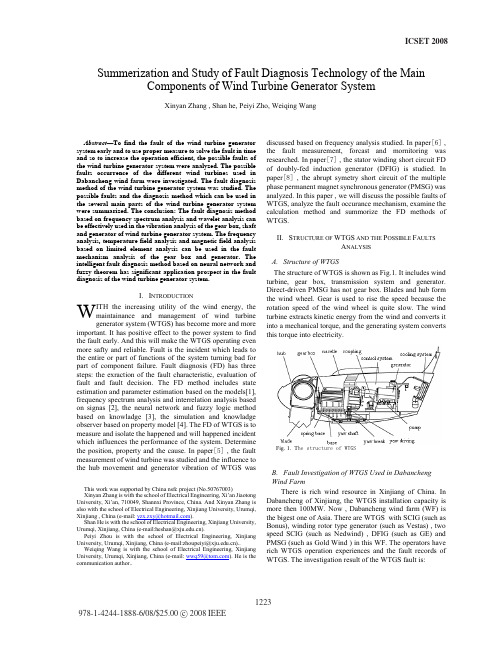
ICSET2008Abstract—To find the fault of the wind turbine generator system early and to use proper measure to solve the fault in time and so to increase the operation efficient, the possible faults of the wind turbine generator system were analyzed. The possible faults occurrence of the different wind turbines used in Dabancheng wind farm were investigated. The fault diagnosis method of the wind turbine generator system was studied. The possible faults and the diagnosis method which can be used in the several main parts of the wind turbine generator system were summarized. The conclusion: The fault diagnosis method based on frequency spectrum analysis and wavelet analysis can be effectively used in the vibration analysis of the gear box, shaft and generator of wind turbine generator system. The frequency analysis, temperature field analysis and magnetic field analysis based on limited element analysis can be used in the fault mechanism analysis of the gear box and generator. The intelligent fault diagnosis method based on neural network and fuzzy theorem has significant application prospect in the fault diagnosis of the wind turbine generator system.I.I NTRODUCTIONITH the increasing utility of the wind energy, themaintainance and management of wind turbinegenerator system (WTGS) has become more and more important. It has positive effect to the power system to find the fault early. And this will make the WTGS operating even more safty and reliable. Fault is the incident which leads to the entire or part of functions of the system turning bad for part of component failure. Fault diagnosis (FD) has three steps: the exraction of the fault characteristic, evaluation of fault and fault decision. The FD method includes state estimation and parameter estimation based on the models[1], frequency spectrum analysis and interrelation analysis based on signas [2], the neural network and fuzzy logic method based on knowladge [3], the simulation and knowladge observer based on property model [4]. The FD of WTGS is to measure and isolate the happened and will happened incident which influences the performance of the system. Determine the position, property and the cause. In paper> @ , the fault measurement of wind turbine was studied and the influence to the hub movement and generator vibration of WTGS was This work was supported by China nsfc project (No.50767003)Xinyan Zhang is with the school of Electrical Engineering, Xi’an Jiaotong University, Xi’an, 710049, Shannxi Province, China. And Xinyan Zhang is also with the school of Electrical Engineering, Xinjiang University, Urumqi, Xinjiang , China (e-mail: yzx.zxy@).Shan He is with the school of Electrical Engineering, Xinjiang University, Urumqi, Xinjiang, China (e-mail:heshan@).Peiyi Zhou is with the school of Electrical Engineering, Xinjiang University, Urumqi, Xinjiang, China (e-mail:zhoupeiyi@)..Weiqing Wang is with the school of Electrical Engineering, Xinjiang University, Urumqi, Xinjiang, China (e-mail: wwq59@). He is the communication author.. discussed based on frequency analysis studied. In paper> @ , the fault measurement, forcast and mornitoring was researched. In paper> @ , the stator winding short circuit FD of doubly-fed induction generator (DFIG) is studied. In paper> @ , the abrupt symetry short circuit of the multiple phase permanent magnet synchronous generator (PMSG) was analyzed. In this paper , we will discuss the possible faults of WTGS, analyze the fault occurance mechanism, examine the calculation method and summorize the FD methods of WTGS.II.S TRUCTURE OF WTGS AND THE P OSSIBLE F AULTSA NALYSISA.Structure of WTGSThe structure of WTGS is shown as Fig.1. It includes wind turbine, gear box, transmission system and generator. Direct-driven PMSG has not gear box. Blades and hub form the wind wheel. Gear is used to rise the speed because the rotation speed of the wind wheel is quite slow. The wind turbine extracts kinetic energy from the wind and converts it into a mechanical torque, and the generating system converts this torque into electricity.B.Fault Investigation of WTGS Used in Dabancheng Wind FarmThere is rich wind resource in Xinjiang of China. In Dabancheng of Xinjiang, the WTGS installation capacity is more then 100MW. Now , Dabancheng wind farm (WF) is the bigest one of Asia. There are WTGS with SCIG (such as Bonus), winding rotor type generator (such as Vestas) , two speed SCIG (such as Nedwind) , DFIG (such as GE) and PMSG (such as Gold Wind ) in this WF. The operators have rich WTGS operation experiences and the fault records of WTGS. The investigation result of the WTGS fault is:Summerization and Study of Fault Diagnosis Technology of the Main Components of Wind Turbine Generator SystemXinyan Zhang , Shan he, Peiyi Zho, Weiqing WangWFig. 1. T KH VWUXFWXUH RI :7*6Generator: The fault occurrence is high in winding rotor type generator, the IGBTs are broken. Before the fault occurrence , there are some phenominon such as increasing of temprature, excessive power output, etc. The windings of stator or rotor were burn or the insulation were broken.Gear box: The tooth, shaft were broken. The heavy wearness of bearing. Because the special weather of Xinjiang, the airstream makes the gear box often operation in a over load condition and can not be lubricated properly. And the over heat phenominon happen in a lot of WTGS under high wind speed. The parts which are failure are different in different types of WTGS and the failure also different in the same types of WTGS because the different installation places.C.The Analysis of the Fault Occurrence Reason of WTGS The fault can happen in every parts of WYGS when it is in operation. We mainly discuss the gear box and generator fault occurrence reason here.The gear box will endure the static and dynamic load which depends on the characteristic of wind wheel and generator, the mass, stiffness and dampness of transmission shaft and coupling, and the operation condition. The machine over speed caused by gust and grid fault can result in the impulse over load. The bearing twist, crooked shaft or some big stiff getting in the meshing parts can turn the tooth broken. Exceeding the fatigue limit under over load or acted by the alternative stress can make the bearing broken. The temperature increases abruptly while in the ordinary operation condition often means the failure of bearing. The over output lasted too long or cooling system failure can result in the high tempreture of oil of gear box. The weather temperature is very low in winter in Xinjiang, if the WTGS always operated in very low temperature, the oil of gear box will become thick and this makes some parts of gear can not be lubricated and so broken.The fault happened in generator includes insulation resistor too low, bearing over heat, winding open circuit and winding short circuit or connected to ground. The possible reasons which make the insulation resistor too low are the high temperature, mechanical damage, moist, dust, conductive particles and other pollution material eroding the winding of the generator[10].The high temperature, wearing, vibration and the carbon brush powder entering the magnetic field air gas can result in the breakdown between the winding phases. The reasons which make winding open circuit and winding short circuit or connected to ground are the winding mechanical broken, damage, fail welding, short circuit between the turns, moist, dust, conductive particles eroding the winding. The over voltage and current caused by the short circuit of the other electrical equipment will make the winding insulation broken or short circuit. The lightning struck can also makes the winding short circuit.III.T HE A PPROACH OF THE F AULT D IAGNOSIS M ETHOD OFWTGSA.Fault Diagnosis MethodFault diagnosis consists fault recognition, fault isolation and fault analysis. The development of efficient fault detection methods has to deal with three main issues: the prerequisite is the choice of signals to be measured because the signals must clearly reflect the component dynamics; the key is the research on suitable signal processing algorithms and the characteristic changes caused by certain faults; the focus is development of efficient classification and diagnosis algorithms. According to P.M.Frank’s idea, fault diagnosis method can be classified as shown in fig.2.B.Fault Diagnosis Method of WTGS AnalysisThe following techniques which are possibly applicable for wind turbine have been identified: vibration analysis, oil analysis, thermography, physical condition of materials, strain measurement, electrical effects, process parameters, visual inspection, performance monitoring, self diagnostic sensors. Strain measurement, acoustic emission, vibration monitoring can be used to detect the failures in the blade trend analysis, based on parameter estimation can be used in pitch control condition monitoring.The parts which have high fault occurrence are gear box, generator and yaw system. We mainly discuss the fault diagnosis method of gear box and generator here. Condition monitoring for gearbox are: vibration analysis based on different sensors, the most commonly used sensor is acceleration sensor, the displacement sensor for inspect the main bearing operating at low speed. Vibration analysis major in the inspection of the frequency related to the rotational speeds. Acoustic emission considers the higher frequency effects which normally attenuate after short period. Oil analysis is used for further inspect diagnosis to approve the first two diagnosis results. Fig.3 shows the fault detection based on frequency spectrum. Based on the level ofamplitudes, status of the signal can be got.Fig. 2. Fault diagnosis method classificationWe build the model of gear and analyze the model using ANSYS based on vibration mechanics and limited element theorem. The condition of frequency and out of shape will be calculated. We also build the temperature field model and analyze the mechanism of fault occurrence of gear.The shaft, gear and bearing of WTGS can vibrate in operation. If there is a fault, the energy distribution and frequency distribution of the vibration signal will vary. The gear will display a different forms under different frequency. The basic vibration quantities such as displace, stress, velocity and strain will change correspond the different frequencies. The normal operation frequency of gear of WTGS is 20Hz~2000Hz. Fig.4 shows the gear form under fault frequency condition. We can find that the teeth of the gear have deformed heavily.Another phenomenon which will lead to the fault of the gear box is the temperature increase. We use ANSYS to analyse the thermal field variation. The thermal stress wascarried out by thermal analysis and the transient thermal analysis is used here. When there is temperature difference, the gas, liquid and solid will have certain heat conduction.The heat transfer or conduction can occur between gear and oil , and thermal convection cab occur between gear oil and gas.The temperature field of gear is shown in fig.5. From the figure , we can find that the meshing gears reachs a thermal balance after 0.5 h.In figure 4, we can see the gear temperature field shows an uneven distribution and the gear temperature distribution is same.Tooth surface of meshed gears have the highest temperature because of the fact that heat transfer between oil and gear is maximum. Gear central exists the lowest temperature because it is far from oil so that the heat transmission is smaller.From gear tooth to gear center, there are different temperature distribution areas. It shows a gradient descent tendency, in every temperature zone, node temperature distribution patterns increas from central part of gear to the the edge.The thermal deformation is caused by temperature field variation with the increase of oil temperature.When the oil temperature is raised, the viscosity of lubricate oil will decrease and the thickness of oil film will be thinner and this will make the oil more easily to enter cracks in tooth surface thus lead to aggravation of cracks of gear-tooth. Therefore,spalling of metal particle occurred at surface of gear-tooth namely the pitting failure of gear surface.Because of the increase of oil temperature,certain degree of expansion has happened, the major deformation mode is the increase of tooth thickness. The main deformation mode of the small gear is to expand outward and no gear-tooth deflection occurrence. The deformation of gear-tooth of scroll wraps is bigger than that of other parts.Deformation of the contact area is decreased due to the heating expansion,which can reduce the shock velocity in meshing to a certain extent.We can find the frictional heat increases with increase of oiltemperature so that the temperature of working area of thegear is the highest one by further analysis and calculation.This will result in the oil film fracture and then causes direct contact and adhesion of tooth surface metal. When the gear issliding and rolling, softer metal is torn in sliding directionwhich results in the forming of surface rills namely gluing.Improving lubrication condition properly can remove scuffing.About the generator fault, we will mainly discuss the faultof DFIG and PMSG used in WTGS. Generator bearing can bemonitored by vibration analysis. The condition of the rotorFig. )ault detection based on frequency spectrum (source Prueftechnik)Fig..4. The form and vibration of gear Fig..5. The temperature distribution of circular spur gear drivingand stator winding can be inspected by temperature. Due to the changing loads , trend analysis based on parameter estimation techniques can be used for early fault detection. Insulation diagnosis can make decision about if there is a fault in insulation parameter and operation performance and forecast the life-span of insulation. Electrical analysis uses frequency spectrum signal to measure the current wave form and then deduce the cause and degree of the fault of the equipment.Using membership function can describe the existence trend of the fault. The threshold can also be modulated by fuzzy logic. But the relation between fault and sign is difficult to get, and diagnosis level depends on the fuzzy knowledge base, so the fail and miss to diagnosis happen easily. Because neural network has the capability to deal with nonlinear problem and can learn by itself, we can use it from the input fault data to deduce the output-fault types and the causes. Wavelet transformation can analyze both in the time scale and in frequency scale. It has multiple resolving power, and can display the signal’s property in both domain. By solving the wavelet transformation of the input and output signals (or data) of a system and then calculation the singularity of them, the fault information can be got by remove the extreme value points caused by the input. The wavelet packet can further decompose the high frequency signal. It has even high resolving power in both time domain and frequency domain. So it can diagnose the fault occurrence time and type of machine.Because the WTGS is very complicated, one fault can be caused by many reasons. Just using one method to diagnose the fault is very difficult. So we use fuzzy neural network to form the diagnosis system. The magnetic field of DFIG is made by both magnetic fields of stator and rotor. The rotation direction of the rotor magnetic field will change correspond the rotation speed of the machine, and the harmonics of the field will lead to the magnetic distortion and torque fluctuation. This will increase the iron loss and attached loss. By calculation the iron loss, rotor temperature, the variation of magnetic field, we can find if the rotor has been damaged. The magnetic path of PMSG is very complicated and the operation point of its magnet steel varies very big in different level of temperature, so the magnet property changes very big, the voltage will fluctuate. Different temperature and load have heavy influence to the voltage and magnetic field. We use limited element calculate the magnetic field and temperature field of the machine and then analyze the mechanism of the fault occurrence.IV.C ONCLUSIONWTGS is a whole entirety, its fault can not be just a mechanical failure or electrical failure, all the fault can be coupled together. And the mechanical fault can lead to the winding vibration, displace and insulation wearing of the generator, and so result in electrical fault. While the electrical fault such as the fault of the rotor or stator winding can lead to gas flux distortion and the electric-magnetic field distribution uneven and then result to mechanical crooked, flexible, unsteady. We will use all the method as described above to diagnose the fault, and at the same time, we will consider the relation between all the parts of WTGS. The intelligent fault diagnosis method based on neural network and fuzzy theorem has significant application prospect in the fault diagnosis of the wind turbine generator system.R EFERENCES[1]Alcorta Garcia, E.and Frank,P.M. “On the relationship betweenobserver and parameter identification based approaches to fault detection”, Proceedings of the forth IFAC world congress., Vol.N, 1996, pp25-29.[2]Frank,P.M. and Ding ,X. , “Frequency domain approach to optimallyrobust residual generation and evaluation for model-based fault diagnosis”. Automatica vol.30, 1993 pp .789-904.[3] Sorsa,T. and Koivo,H.N. “Application of artificeial neural networks inprocess fault diagnosis”. Automatica vol.29, 1993, pp.843-849.[4]R.J.Patton, “Fuzzy observers for non-linear dynamic systems faultdiagnosis”. Proceedings of the 37th IEEE conference on decision of control . Florida ,USA,1998, pp.84-89.[5]P.Caselitz and J. Giebhandt, “Development of a fault detection systemfor wind energy convertors” , EUWEC’96, Goeteborg, pp.1004-1007..[6]P.Caselitz and J. Giebhandt, “On-line fault detection and prediction inwind energy convertors”, EUWEC’97, Dublin.[7]LU,Q.F,Cao,Z.T,Ritche,E., “Model of stator inter-turn short circuitfault in doubly-fed induction generators for wind turbine”, Power electronics specialists conference, 2004 IEEE 35th annual[8]Qiao Mingzhong, The Analysis of Abrupt Symetry Short Circuit ofmulti- phase PMSG, Journal of Electrical Engineering Technologe, April 0f 2004 ,Vol.19 No.4..[9]Wang Chengxu, Zhang Yuan, Wind Power, China Electric PowerPublisher, Beijing, 2005, p49-158[10]Gong Jingyuan, Engineering Technique Handbook of WF, MechanicalIndustry Publisher, Beijing, China, 2004, p144-155.。

汽车电路故障常用诊断与检测的流程1.第一步是检查汽车的电池是否正常工作。
The first step is to check if the car's battery is working properly.2.如果电池正常,接着就要检查保险丝是否出现短路或断裂。
If the battery is okay, then check for any short circuits or breakage in the fuses.3.再接着检查车辆的电动机和发电机是否运转正常。
Next, check if the car's electric motor and generator are operating normally.4.如果发电机运转不正常,可能是需要更换电刷或修理转子。
If the generator is not working properly, it may be necessary to replace the brushes or repair the rotor.5.还要检查车辆的电线连接是否紧固良好,没有松动或生锈。
Also, check the car's wire connections to ensure they are secured and free from loosening or rust.6.若要确认故障点,可以使用电路测试仪来逐一测试每个电路。
To pinpoint the fault, a circuit tester can be used totest each circuit one by one.7.如果车辆使用了计算机系统,就要检查计算机系统是否显示错误代码。
If the vehicle is equipped with a computer system, checkif it displays error codes.8.检查车辆的传感器和开关,确保它们在适当的时候开启和关闭。

Simple Methods for Calculating Short Circuit CurrentWithout a ComputerBy Dennis McKeown, PEGE Senior System Application EngineerA Short Circuit analysis is used to determine the magnitude of short circuit current the system is capable of producing and compares that magnitude with the interrupting rating of the overcurrent protective devices (OCPD). Since the interrupting ratings are based by the standards, the methods used in conducting a short circuit analysis must conform to the procedures which the standard making organizations specify for this purpose. In the United States, the America National Standards Institute (ANSI) publishes both the standards for equipment and the application guides, which describes the calculation methods.Short circuit currents impose the most serious general hazard to power distribution system components and are the prime concerns in developing and applying protection systems. Fortunately, short circuit currents are relatively easy to calculate. The application of three or four fundamental concepts of circuit analysis will derive the basic nature of short circuit currents. These concepts will be stated and utilized in a step-by-step development.The three phase bolted short circuit currents are the basic reference quantities in a system study. In all cases, knowledge of the three phase bolted fault value is wanted and needs to be singled out for independent treatment. This will set the pattern to be used in other cases.A device that interrupts short circuit current, is a device connected into an electric circuit to provide protection against excessive damage when a short circuit occurs. It provides this protection by automatically interrupting the large value of current flow, so the device should be rated to interrupt and stop the flow of fault current without damage to the overcurrent protection device. The OCPD will also provide automatic interruption of overload currents.Listed here are reference values that will be needed in the calculation of fault current. Impedance Values for Three phase transformersHV Rating 2.4KV – 13.8KV 300 – 500KVA Not less than 4.5%HV Rating 2.4KV – 13.8KV 750 – 2500KVA 5.75%General Purpose less then 600V 15 – 1000KVA 3% to 5.75%Reactance Values for Induction and Synchronous MachineX” SubtransientSalient pole Gen 12 pole 0.1614 pole 0.21Synchronous motor 6 pole 0.158-14 pole 0.20Induction motor above 600V 0.17Induction motor below 600V 0.25TRANSFORMER FAULT CURRENTCalculating the Short Circuit Current when there is a Transformer in the circuit. Every transformer has “ %” impedance value stamped on the nameplate. Why is it stamped? It is stamped because it is a tested value after the transformer has been manufactured. The test is as follows: A voltmeter is connected to the primary of the transformer and the secondary 3-Phase windings are bolted together with an ampere meter to read the value of current flowing in the 3-Phase bolted fault on the secondary. The voltage is brought up in steps until the secondary full load current is reached on the ampere meter connected on the transformer secondary.So what does this mean for a 1000KVA 13.8KV – 480Y/277V.First you will need to know the transformer Full Load AmpsFull Load Ampere = KVA / 1.73 x L-L KVFLA = 1000 / 1.732 x 0.48FLA = 1,202.85The 1000KVA 480V secondary full load ampere is 1,202A.When the secondary ampere meter reads 1,202A and the primary Voltage Meter reads 793.5V. The percent of impedance value is 793.5 / 13800 = 0.0575. Therefore;% Z = 0.0575 x 100 = 5.75%This shows that if there was a 3-Phase Bolted fault on the secondary of the transformer then the maximum fault current that could flow through the transformer would be the ratio of 100 / 5.75 times the FLA of the transformer, or 17.39 x the FLA = 20,903ABased on the infinite source method at the primary of the transformer. A quick calculation for the Maximum Fault Current at the transformer secondary terminals is FC = FLA / %PU Z FC = 1202 / 0.0575 = 20,904AThis quick calculation can help you determine the fault current on the secondary of a transformer for the purpose of selecting the correct overcurrent protective devices that can interrupt the available fault current. The main breaker that is to be installed in the circuit on the secondary of the transformer has to have a KA Interrupting Rating greater then 21,000A. Be aware that feeder breakers should include the estimated motor contribution too. If the actual connected motors are not known, then assume the contribution to be 4 x FLA of the transformer. Therefore, in this case the feeders would be sized at 20.904 + (4 x 1202 = 25,712 AmpsGENERATOR FAULT CURRENTGenerator fault current differs from a Transformer. Below, we will walk through a 1000KVA example.800KW 0.8% PF 1000KVA 480V 1,202FLAKVA = KW / PFKVA = 800 / .8KVA = 1000FLA = KVA / 1.732 x L-L VoltsFLA = 1000 / 1.732 x 0.48FLA = 1,202(As listed in the table for generator subtransient X” values is 0.16)FC = FLA / X”FC = 1202 / 0.16FC = 7,513ASo, the fault current of a 1000KVA Generator is a lot less then a 1000KVA transformer. The reason is the impedance value at the transformer and Generator reactance values are very different. Transformer 5.75% vs. a Generator 16%SYSTEM FAULT CURRENTBelow is a quick way to get a MVA calculated value. The MVA method is fast and simple as compared to the per unit or ohmic methods. There is no need to convert to an MVA base or worry about voltage levels. This is a useful method to obtain an estimated value of fault current. The elements have to be converted to an MVA value and then the circuit is converted to admittance values.Utility MVA at the Primary of the TransformerMVAsc = 500MVATransformer Data13.8KV - 480Y/277V1000KVA Transformer Z = 5.75%MVA Value1000KVA / 1000 = 1 MVAMVA Value = 1MVA / Z pu = 1MVA / .0575 = 17.39 MVAUse the admittance method to calculate Fault Current1 / Utility MVA + 1 / Trans MVA = 1 / MVAsc1 / 500 + 1 / 17.39 = 1 / MVAsc0.002 + 0.06 = 1/ MVAscMVAsc = 1 / (0.002 + 0.06)MVAsc = 16.129FC at 480V = MVAsc / (1.73 x 0.48)FC = 16.129 / 0.8304FC = 19.423KAFC = 19, 423 AThe 480V Fault Current Value at the secondary of the 1000KVA transformer based on an Infinite Utility Source at the Primary of the transformer as calculated in the Transformer Fault Current section in this article is 20,904AThe 480V Fault Current Value at the secondary of the 1000KVA transformer based on a 500MVA Utility Source at the Primary of the transformer as calculated in the System Fault Current section in this article is 19,432AThe 480V Fault Current Value at the secondary of the 1000KVA transformer based on a 250MVA Utility Source at the Primary of the transformer the calculated value is 18,790AWhen the cable and its length is added to the circuit the fault current in a 480V system will decrease to a smaller value. To add cable into your calculation use the formula. Cable MVA Value MVAsc = KV2 / Z cable. Use the cable X & R values to calculate the Z value then add to the Admittance calculation as shown in this article.The conclusion is that you need to know the fault current value in a system to select and install the correct Overcurrent Protective Devices (OCPD). The available FC will be reduced as shown in the calculations when the fault current value at the primary of the transformer is reduced. If the infinite method is applied when calculating fault current and 4 x FLA is added for motor contributions, then the fault current value that is obtained will be very conservative. This means the calculated value in reality will never be reached, so you reduce any potential overcurrent protection device failures due to fault current.。


网络故障处理经验交流材料网络故障处理经验交流材料尊敬的各位同事:大家好!我很荣幸能在这里与大家分享一些网络故障处理经验。
在日常工作中,我们经常会遇到各种各样的网络故障,例如互联网连接问题、服务器崩溃、网络延迟等等。
而如何快速而有效地处理这些网络故障,提高故障恢复速度,是我们每个网络工程师都需要重视和学习的。
一、故障诊断和定位故障诊断和定位是解决网络故障的第一步。
在遇到故障时,我们首先要明确故障的表现和影响范围,例如是否只有某一个用户受到影响,还是整个网络都无法正常使用。
然后,我们可以通过以下方法进行故障诊断和定位:1.检查网络设备:首先要检查网络设备的状态,例如路由器、交换机是否工作正常,是否有报错信息。
我们可以通过命令行界面、网管工具或者设备的LED指示灯来查看设备的运行状态。
2.故障分析工具:利用网络故障诊断工具,例如Wireshark、网络探测工具等,对网络流量进行抓包分析。
通过分析抓到的数据包,我们可以了解网络的通信情况,找出可能存在的故障原因。
3.远程登陆设备:如果有远程登陆设备的权限,我们可以尝试远程登陆故障设备,检查设备的配置和日志信息,查看是否有异常。
二、问题解决和恢复当我们成功地诊断出故障原因后,就可以针对具体问题采取相应的解决方法。
以下是一些常见的网络故障解决方法:1.重启设备:重启设备是解决许多网络故障的常用方法。
在重启设备之前,我们可以先备份设备的配置,以免丢失重要信息。
2.更改设备配置:有时候,网络故障是由于设备的配置问题所导致的。
在修改设备配置之前,我们要先了解设备的当前配置,然后再根据故障原因进行相应的调整。
3.更换硬件设备:如果设备本身存在硬件故障,例如断电、电路短路等,我们可以尝试更换硬件设备来解决问题。
4.联系供应商或厂家:如果遇到一些复杂的网络故障,我们可以联系设备供应商或厂家的技术支持团队,寻求他们的帮助和建议。
三、故障记录和总结在解决网络故障的过程中,我们要及时、准确地记录故障处理的过程和结果。


Chapter 24DC Short-Circuit AnalysisIn order to assure the safe operation of DC systems, whenever there is any changes in the system related to sources, loads, and power transmission components, a DC Short-Circuit Analysis must be carried out to evaluate system conditions under a fault and assess protective device ratings. A complete short-circuit calculation should provide details of fault current variations at the fault location as well as for contributing branches, from the initiation of the fault to its end. Due to the complexities involved in source behaviors and the non-linearity characteristics of the equipment, such calculations are very extensive and therefore the maximum short-circuit current is often calculated instead for examination of protective device ratings.DC Short-Circuit Analysis Introduction In compliance with IEEE Std. 946, the PowerStation DC short-circuit program calculates the total fault current, current contributions from different sources, and the rise time constant of the total fault current. It can conduct calculations on both radial and looped systems. The fault under consideration is a short-circuit between the positive and the negative terminals at the fault location. The contributing sources to the short-circuit current include charger/rectifier, UPS, battery, and DC motor. These sources can be modeled as a constant current source or a constant voltage source behind an impedance. For a charger/rectifier source, the AC system equivalent impedance on the AC side can also be considered.For each DC protective device, PowerStation calculates the bus fault current as well as the maximum current that flows through the device and flags the user in an outstanding color for underrated devices. The calculation results are reported in a Crystal Reports format as well as in a one-line diagram display. The Crystal Reports format provides detailed information about the study, including all the input data used in the calculation, fault current, contributions from different sources, and device rating validation summary, etc. The format and content of the Crystal Reports output report can be customized by the user. The one-line diagram display provides you with a direct visual representation of the system under fault conditions. It displays the short-circuit current at the faulted bus, fault current contributions on surrounding branches, as well as the system voltage profile under the fault.24.1 Study ToolbarThe DC Short-Circuit Study Toolbar will appear on the screen when you are in DC Short-Circuit Study mode.Run DC Short-Circuit AnalysisClick on this button to run a DC short-circuit calculation.Display OptionsClick on this button to customize the information and results annotations displayed on the one-line diagram in DC Short-Circuit mode.DC Short-Circuit Report ManagerClick on this button to open the DC Short-Circuit Report Manager. Here you can specify the Crystal Reports format for your output reports. A detailed explanation of the DC Short-Circuit Report Manager is in the Output Reports section.Halt Current CalculationClick on the Stop Sign button to halt the current calculation.Get On-Line DataIf the ETAP key installed on your computer has the on-line feature, you can copy the online data from the on-line presentation to the current presentation.Get Archived DataIf the ETAP key installed on your computer has the on-line feature, you can copy the archived data to the current presentation.24.2 Study Case EditorThe DC Short-Circuit Study Case Editor contains parameter settings required to perform a short-circuit calculation. The calculation results are dependent on these settings. When a new study case is created, ETAP PowerStation provides you with the default parameters. However, you want to check these parameters to make sure that they are set as required.The DC Short-Circuit Study Case Editor contains two pages: the Info page and the Source Model page. In the Info page, you can select faulted buses and specify contribution level, etc. In the Source Model page, you specify the type of model for chargers and batteries, as well as what loads need to be considered in a study.24.2.1 Info PageStudy Case IDIDEnter a unique alphanumeric ID with a maximum of 12 characters.ReportSpecify the contribution level the report should encompass.Bus SelectionHere you can select which buses to Fault, Don’t Fault, or click on the All Buses check box to fault all buses. Note that you can fault buses (or remove faults) directly from the one-line diagram by right clicking on the desired bus.Remarks 2nd LineYou can enter up to 120 alphanumeric characters in this remark box. Information entered here will be printed on the second line of every output report page header. These remarks can provide specific information regarding each study case. Note that the first line of the header information is global for all study cases and entered in the Project Information Editor.24.2.2 Source Model PageThis page allows you to specify the type of models you want the program to use in a short-circuit calculation.Charger Contributions Based onA charger can be represented as a constant current source or a constant voltage source behind impedance. As a constant current source, it injects a constant current into the system when a fault occurs.Editor SelectionClick on this option to select the model type as specified in the editor for individual chargers.Fixed SC ContributionClick on this option to use the constant current model for all the charges in the system.AC System ImpedanceClick on this option to use the constant voltage model for all the charges in the system.Battery Contributions Based onA battery can be represented as a constant current source or a constant voltage source behind impedance. As a constant current source, it injects a constant current into the system when a fault occurs. The current injected into the system is equal to a constant multiplied by its 1-minute discharge rate.Editor SelectionClick on this option to select the model type as specified in the editor for individual batteries.Constant Current (K*1-Min-Rating*String)Click on this option to use the constant current model for all the batteries in the system.Voc Behind Battery ImpedanceClick on this option to use the constant voltage model for all the batteries in the system.Motor Internal VoltageA motor, or the motor load portion of a lump load, is modeled as a constant voltage source behind an impedance. You can specify the internal voltage value by selecting one of the following two options: 100% of Motor Rated VoltageClick on this option to use the motor rated voltage as the internal voltage.Percent of Motor Rated VoltageClick on this option to specify the motor internal voltage in percent based on the motor rated voltage. Short-Circuit Contributions Based onThis section provides you with an option to skip certain load elements in a short-circuit analysis. Note that static loads are also considered in a DC short-circuit analysis and their presence reduces total fault current.Load Status OnlySelect this option to include loads in the short-circuit study based on load status. For the current system configuration, loads that have either the Continuous or Intermittent status will be considered in the study. Loads that have the Spare status will be excluded from the study. Note that when this option is selected all of the elementary diagram loads will be included in the study.Load Category OnlySelect this option to use the loading percent to determine which loads will be included in the short-circuit calculation. Once this option is selected, you can specify a loading category in the loading category selection box. All loads that have non-zero loading percent for the selected loading category will be included in the short-circuit calculation.Use Both Above OptionsSelect this option to use both load status and loading category to determine loads to be included in the short-circuit calculation. When this option is selected, all the loads that satisfy either or both of the above two criterions will be included in the short-circuit study.24.3 Display OptionsThe DC Short-Circuit Analysis Display Options consist of a Results page and three pages for AC, AC-DC, and DC info annotations. Note that the colors and displayed annotations selected for each study are specific to that study.24.3.1 Results PageColorThe drop down list allows you to select a color for displaying calculation results on the one-line diagram. Show UnitsWhen this box is checked the unit for the calculation results will be displayed on the one-line diagram along with the results.VoltageBusClick on this check box to display bus voltage on the one-line diagram.Bus Voltage Unit SelectionFrom the drop down list you can select to display bus voltage in percent or volt.Display Faulted BusFault Current Rise Time-ConstantClick on this option to display the fault current rise time-constant in ms for faulted buses.Equivalent Fault RClick on this option to display the equivalent fault resistance in ohms for faulted buses.Display ContributionConverter, Battery, & LoadClick on any or all of these check boxes to display short-circuit contribution from these components on the one-line diagram.24.3.2 AC PageThis page includes options for displaying info annotations for AC elements.ColorSelect the color for information annotations to be displayed on the one-line diagram.IDSelect the check boxes under this heading to display the ID of the selected AC elements on the one-line diagram.RatingSelect the check boxes under this heading to display the ratings of the selected AC elements on the one-line diagram.Device Type RatingGen. (Generator) kW / MWPower Grid (Utility) MVAscMotor HP / kWLoad kVA / MVAPanel Connection Type (# of Phases - # of Wires)Transformer kVA / MVABranch, Impedance Base MVABranch, Reactor Continuous AmpsCable / Line # of Cables - # of Conductor / Cable - SizeBracingBus kANode Bus Bracing (kA)CB Rated Interrupting (kA)Fuse Interrupting(ka)Relay 50/51 for Overcurrent RelaysPT & CT Transformer Rated Turn RatiokVSelect the check boxes under this heading to display the rated or nominal voltages of the selected elements on the one-line diagram.For cables/lines, the kV check box is replaced by the button. Click on this button to display the cable/line conductor type on the one-line diagram.ASelect the check boxes under this heading to display the ampere ratings (continuous or full-load ampere) of the selected elements on the one-line diagram.For cables/lines, the Amp check box is replaced by the button. Click on this button to display the cable/line length on the one-line diagram.ZSelect the check boxes under this heading to display the rated impedance of the selected AC elements on the one-line diagram.Device Type ImpedanceGenerator Subtransient reactance Xd”Power Grid (Utility) Positive Sequence Impedance in % of 100 MVA (R + j X)LRCMotor %Transformer Positive Sequence Impedance (R + j X per unit length)Branch, Impedance Impedance in ohms or %Branch, Reactor Impedance in ohmsCable / Line Positive Sequence Impedance (R + j X in ohms or per unit length)D-YSelect the check boxes under this heading to display the connection types of the selected elements on the one-line diagram.For transformers, the operating tap setting for primary, secondary, and tertiary windings are also displayed. The operating tap setting consists of the fixed taps plus the tap position of the LTC. Composite MotorClick on this check box to display the AC composite motor IDs on the one-line diagram, then select the color in which the IDs will be displayed.Use Default OptionsClick on this check box to use PowerStation’s default display options.24.3.3 AC-DC PageThis page includes options for displaying info annotations for AC-DC elements and composite networks. ColorSelect the color for information annotations to be displayed on the one-line diagram.IDSelect the check boxes under this heading to display the IDs of the selected AC-DC elements on the one-line diagram.RatingSelect the check boxes under this heading to display the ratings of the selected AC-DC elements on the one-line diagram.Device Type RatingCharger AC kVA & DC kW (or MVA / MW)Inverter DC kW & AC kVA (or MW / MVA)UPS kVAVFD HP / kWkVClick on the check boxes under this heading to display the rated or nominal voltages of the selected elements on the one-line diagram.AClick on the check boxes under this heading to display the ampere ratings of the selected elements on the one-line diagram.Device Type AmpCharger AC FLA & DC FLAInverter DC FLA & AC FLAUPS Input, output, & DC FLAComposite NetworkClick on this check box to display the composite network IDs on the one-line diagram, then select the color in which the IDs will be displayed.Use Default OptionsClick on this check box to use PowerStation’s default display options.24.3.4 DC PageThis page includes options for displaying info annotations for DC elements.ColorSelect the color for information annotations to be displayed on the one-line diagram.IDSelect the check boxes under this heading to display the IDs of the selected DC elements on the one-line diagram.DC Short-Circuit Analysis Display Options RatingSelect the check boxes under this heading to display the ratings of the selected DC elements on the one-line diagram.Device Type RatingHourBattery AmpereMotor HP / kWLoad kW / MWElementary Diagram kW / MWConverter kW / MWCable # of Cables - # of Conductor / Cable - SizekVSelect the check boxes under this heading to display the rated or nominal voltages of the selected elements on the one-line diagram.For cables, the kV check box is replaced by the button. Click on this button to display the conductor type on the one-line diagram.ASelect the check boxes under this heading to display the ampere ratings of the selected elements on the one-line diagram.For cables, the Amp check box is replaced by the button. Click on this button to display the cable length (one way) on the one-line diagram.ZSelect the check boxes under this heading to display the impedance values of the cables and impedance branches on the one-line diagram.Composite MotorClick on this check box to display the DC composite motor IDs on the one-line diagram, then select the color in which the IDs will be displayed.Use Default OptionsClick on this check box to use PowerStation’s default display options.24.4 Calculation MethodsThe PowerStation DC short-circuit program can perform fault analysis for a radial or a looped system. It calculates the maximum system fault current and contributions from individual sources. The fault under consideration is assumed to be a short-circuit between the positive and negative terminals at the fault location. Fault current contributing sources include chargers/rectifiers, UPS, batteries, and DC motors. These sources can be modeled either as constant current sources or constant voltage sources behind an impedance, as specified by the user. It is assumed that these sources will reach their maximum contribution level at the same time, which results in a conservative solution. The program also calculates the rise time of fault current based on the equivalent R and L at the fault location. When calculating short-circuit current, inductance values for all of the system components are neglected. These inductance values are used in calculating fault current rise time.24.4.1 Procedure for DC Short-Circuit CalculationIn a DC short-circuit calculation, a contributing source may be represented by different models, either as a voltage source or as a current source. Even the sources that are represented as constant voltage sources may have different per unit values. This is different from the AC short-circuit calculation by the IEEE method, where a prefault voltage is specified and a circuit network is solved to find the fault current. In the DC short-circuit calculation, a two-step procedure is adopted that applies the superposition theorem to calculate fault current. The two steps are voltage profile calculation and short-circuit current calculation. In the first step of the calculation, the short-circuit current sources such as charger, UPS, battery, and motor are modeled as specified in the study case editor and individual element editors. They may be modeled as constant current sources or as constant voltage sources behind an impedance. Based on this system, a load flow calculation is conducted to determine system voltage profile and current flows. These voltage values will be used in the second step as the prefault voltage for short current calculation.In the second step of the calculation, the program calculates fault current and contributions for each bus to be faulted with the bus voltage calculated in the first step as the prefault voltage.In addition to fault current, the program also calculates the equivalent R and L at the faulted bus, based on the separate R and L network. Using the equivalent R and L, it calculates the current rise time constant for the fault.24.4.2 Short-Circuit Current Rise Time Constant CalculationThe short-circuit current reaches its maximum value at a rate depending on the system configuration and the resistance and inductance values of all the elements in the system. For a radial system, it depends on the system R/L ratio, which is simple to calculate. However, for a looped network with multiple sources, it is rather complicated to determine the rise time constant of the short-circuit current.PowerStation calculates the rise time constant based on the equivalent R and L at the fault location.24.4.3 Device Rating EvaluationOne of the major purposes of conducting a short-circuit calculation is to evaluate device rating under fault conditions, such as bus rating and protective device ratings. For each DC protective device, PowerStation calculates the bus fault current and the maximum current that flows through the device. The program then compares the device rating against the maximum through current. If an underrated condition occurs, PowerStation will flag the underrated condition in the text report as well as in the one-line display. 24.4.4 Component ModelsChargerA charger can be represented as a constant current source or a constant voltage source behind an impedance. As a constant current source, it injects into the system a constant current equal to its rated current multiplied by the Imax specified in the Rating page of the charger editor.When modeled as a constant voltage source behind an impedance, the rated voltage is used as the internal voltage. The AC system Z specified in the SC page of the Charger Editor is converted to the DC side and used as the impedance in the model.UPSA UPS (Uninterruptible Power Supply) is represented as a constant current source. It injects into the system a constant current equal to its rated current multiplied by the Imax specified in the Rating page of the UPS Editor.BatteryA battery can be represented as a constant current source or a constant voltage source behind an impedance. As a constant current source, it injects into the system a constant current equal to its 1 minute discharging current multiplied by a K factor specified in the SC page of the Battery Editor.When modeled as a constant voltage source behind an impedance, the internal voltage depends on the option selected in the Battery Editor. These options include using the rated voltage or the value calculated based on the battery specific gravity and minimum operating temperature.DC ConverterA DC converter is used to change the voltage level in a DC system. If a fault occurs on the output side of the system, the DC converter is modeled as a constant current source injecting into the system a constant current. This current is equal to its rated current multiplied by the Imax specified in the Rating page of the DC Converter Editor.When calculating fault current contributions, the calculation does not extend into the input side of the system. In case a DC converter has the same input and output rated voltage values, and it is involved in any loop as the only DC converter, the program stops the calculation and posts a message to inform the user.DC MotorA DC motor is modeled as a constant voltage source behind an impedance. The internal voltage value can be specified in the DC Short-Circuit Study Case Editor. The impedance is specified in the SC page of the DC Motor Editor.DC Lumped LoadA DC lumped load is modeled as a constant voltage source behind an impedance. The internal voltage value can be specified in the DC Short-Circuit Study Case Editor. The impedance is specified in the SC Imp page of the DC Lumped Load Editor.Note that only the motor loads of the lumped loads contribute short-circuit currents, i.e., if the percent motor load of a lumped load is greater than zero, the motor load part will be modeled the same as a DC motor, while the static load part will be represented as a static load with no short-circuit contribution. DC Static & Elementary Diagram LoadsDC static loads are included in short-circuit calculations. The presence of static loads provide shunt paths for short-circuit current and hence reduce the total fault current. An elementary diagram (ED) load is treated the same as a static load.DC CableIn order to achieve conservative results, in a DC short-circuit analysis, the cable resistance is calculated at the minimum temperature entered in the Cable Editor.24.5 Required Data24.5.1 SourceChargerInfo Page• Charger ID• Bus connection dataRating Page• All the data in this page are required for DC load flow calculationsSC Page• Data in the SC Contribution for DC System section• AC System Z data is required if the Based on AC System Z option is selected UPSInfo Page• UPS ID• Bus connection dataRating Page• AC rating data• DC rating data• Auction diode optionSC Imp Page• SC Contribution to DC System section dataBatteryInfo Page• Battery ID• Bus connection data• Number of stringsRating Page• Number of cellsSC Page• Battery Library type data: Rp, time constant, SG, Vpc, and 1-min-rating • Short-circuit model data• External impedance data• Voc per cell data24.5.2 LoadDC MotorInfo Page• Motor ID• Bus connection data • Configuration status • QuantityRating Page• Rating data• Load category dataSC Page• SC parametersLump LoadInfo Page• Lump load ID• Bus connection data • Configuration status Rating Page• Rating section data• Motor/static load percent • Load category dataSC ImpPage• SC parametersStatic LoadInfo Page• Static load ID• Bus connection data • Configuration status • QuantityRating Page• Rating section data• Load category dataED LoadInfo Page• ED load ID• Bus connection dataRating Page• Rating section data• Load category data24.5.3 BranchDC CableInfo Page• Cable ID• Bus connection data• Cable length• Number of cables per phase Impedance Page• Cable resistance and inductance• Units section data• Base and minimum operating temperature DC ImpedanceInfo Page• DC impedance ID• Bus connection data• Impedance resistance and inductance 24.5.4 DC ConverterInfo Page• DC converter ID• Bus connection dataRating Page• Rating section data• SC contribution data24.5.5 Protective DeviceIf the data for a protective device has been entered by the user, the DC short-circuit calculation will compare the short-circuit current against device rating and flag the user if the device is underrated.DC CBInfo Page• ID• Bus connection data• Rated V• SC kADC FuseInfo Page• ID• Bus connection dataRating Page• Rated V• Interrupting kADC Single-Throw SwitchInfo Page• ID• Bus connection data• Rated V• Momentary kADC Double-Throw SwitchInfo Page• ID• Bus connection data• Rated V• Momentary kA24.5.6 Study CaseSimilar to any other study, you are always required to run a DC short-circuit calculation. When a DC short-circuit calculation is initiated by the user, PowerStation uses the study case currently showing in the study case editor in the calculation. Every field in a study case has its default value. However, it is important to set the values in the study case correctly to meet your calculation requirements.24.6 Output ReportsThe DC short-circuit calculation results are reported both on the one-line diagram and in the Crystal Reports format. The graphical one-line diagram displays the calculated fault currents, time constant for current rise, equivalent resistance at the faulted bus, as well as fault contributions from neighboring buses. You can use the Display Options Editor to specify the content to be displayed. It also flags underrated protective devices in red.The Crystal Reports format provides you with detailed information for a DC short-circuit analysis. You can utilize the DC Short-Circuit Report Manager to help you view the output report.24.6.1 DC Short-Circuit Report ManagerTo open the DC Short-Circuit Report Manager, simply click on the View Output File button on the DC Short-Circuit Toolbar. The editor includes four pages (Complete, Input, Result, and Summary) representing different sections of the output report. The Report Manager allows you to select formats available for different portions of the report and view it via Crystal Reports. There are several fields and buttons common to every page, as described below.Output Report NameThis field displays the name of the output report you want to view.Project File NameThis field displays the name of the project file based on which report was generated, along with the directory where the project file is located.HelpClick on this button to access Help.OK / CancelClick on the OK button to dismiss the editor and bring up the Crystal Reports view to show the selected portion of the output report. If no selection is made, it will simply dismiss the editor. Click on the Cancel button to dismiss the editor without viewing the report.Complete PageOn this page there is only one format available, Complete, which brings up the complete report for the DC short-circuit study. The complete report includes input data, results, and summary reports.Input Data PageThis page allows you to select different formats for viewing input data, grouped according to type. They include:BatteryBranch ConnectionBusCableConverterCoverLoadsResult PageThis page allows you to select formats to view the short-circuit result portion of the output report.Summary PageThis page allows you to select formats to view summary reports of the output report. The only summary report format available is the Interrupting Current format.24.6.2 View Output Reports From Study Case ToolbarThis is a shortcut for the Report Manger. When you click on the View Output Report button, PowerStation automatically opens the output report, which is listed in the Study Case Toolbar with the selected format. In the picture shown below, the output report name is Untitled and the selected format is Complete.。

short circuit英语介绍"Short Circuit" is a term used to describe a situation in an electrical circuit where the flow of electric current deviates from its intended path due to a low-resistance connection between two conductive elements. This can resultin an unintentional bypass of other components in the circuit, leading to potential damage or failure of the circuit.A short circuit typically occurs when there is a breakdown in insulation material or when conductive materials come into direct contact with each other. This can be causedby various factors such as overheating, physical damage, or manufacturing defects.When a short circuit occurs, a large amount of currentcan flow through the circuit, creating a surge of electrical energy. This can cause excessive heat generation, sparks, oreven explosions depending on the magnitude of the current and the presence of flammable materials nearby.In order to prevent short circuits, several safety measures are implemented. These measures include the use of properly insulated wires, circuit breakers, fuses, and protective devices that can detect and interrupt the flow of excessive current.Overall, short circuits pose a significant risk and can cause serious damage to electrical systems. It is important to promptly identify and fix short circuits to ensure the safety and proper functioning of electrical circuits.。

short circuit英语介绍-回复标题:[Short Circuit: An Introduction to Electrical Circuits]IntroductionIn the realm of electrical engineering, one concept that stands out as a fundamental building block is that of an electric circuit. More specifically, short circuits form an integral part of this field and are often studied for their significant implications on electrical systems. In this article, we will delve into the world of short circuits, exploring what they are, how they occur, their effects, and ways to prevent them.1. What is a Short Circuit?A short circuit, also known as a 'short' or 'fault', is an abnormal condition in an electrical circuit where an unintendedlow-resistance path forms between two nodes of an electrical circuit. This results in excessive current flow through the new path, which can cause overheating, damage to equipment, and in some cases, fires.2. How does a Short Circuit Occur?A short circuit typically occurs when a live wire (carrying current) comes into direct contact with a neutral wire or ground wire. The low resistance of this connection allows a large amount of current to flow through it, much more than the normal operating current of the circuit.This can happen due to various reasons like insulation failure on wires, loose connections, exposed wires coming into contact, or even foreign objects falling into electrical panels. In essence, any situation that reduces the resistance between the live and neutral/ground conductors can potentially result in a short circuit.3. Effects of a Short CircuitThe immediate effect of a short circuit is a sudden increase in current flow. This surge in current can lead to several outcomes:- Overheating: Excessive current generates heat, which can overheat wires, cables, and other components, causing them to melt or catch fire.- Tripping Circuit Breakers/Fuses: To protect the circuit from damage, protective devices such as circuit breakers or fuses will trip or blow respectively, interrupting the flow of electricity.- Damage to Equipment: Sustained high currents can damage electronic components and appliances connected to the circuit.- Shock Hazards: A person touching a live conductor during a short circuit could receive an electric shock, which can be fatal depending on the severity of the fault.4. Preventing Short CircuitsGiven the potential dangers associated with short circuits, it is essential to take precautions to prevent them. Some measures include:- Regular Maintenance: Periodically inspect electrical installations and repair any damaged wiring or loose connections.- Proper Wiring Practices: Ensure all wiring is done according to electrical codes and standards, with proper insulation on wires and secure connections.- Use of Circuit Protection Devices: Install circuit breakers or fuses to limit the current in case of a short circuit.- Grounding: Proper grounding of electrical systems helps to safely dissipate excess energy during a fault, reducing the risk of damage or fire.- Safety Switches: Residual Current Devices (RCDs) can detect imbalances in current flow and quickly disconnect the power supply in case of a fault.5. ConclusionIn conclusion, short circuits play a critical role in understanding the behavior of electrical systems. By being aware of the causes, effects, and prevention methods, individuals can ensure safer electrical installations and minimize risks associated with these faults. It's crucial to remember that prevention is always better than cure, especially when dealing with electrical hazards.。

电气传动2022年第52卷第7期摘要:汇流集电线故障是并网双馈型风电场最为常见的故障之一。
由于撬棒系统中卸流电阻的影响,双馈风机在汇流集电线发生不对称故障后,其正、负序阻抗将会根据转差率的不同产生不同的特性,从而影响传统自适应电流速断保护的选择性,造成风电机组的大规模误切除,降低双馈型风电场内部的可靠性与并网稳定性。
鉴于此,为了改善双馈型风电场的继电保护性能,基于考虑撬棒动作后的双馈风机阻抗特性,提出了一种适用于35kV 汇流集电线的自适应电流速断保护,并对其具体的整定计算进行了详细的分析。
基于PSCAD 的仿真模型验证了所提保护方法与整定计算的正确性与有效性。
关键词:汇流线路短路故障;双馈型风场;电流速断保护;整定计算;阻抗特性中图分类号:TM28文献标识码:ADOI :10.19457/j.1001-2095.dqcd22194Instantaneous Protection for the Collector Lines of Doubly -fed Wind Farm Considering CrowbarLI Xuhui 1,XIE Baihuang 2,HUANG Xiaoyong 1,XU Yan 3(1.Shangluo Power Supply Bureau ,State Grid Shaanxi Electric Power Company ,Shangluo726000,Shaanxi ,China ;2.Control Center ,Shaanxi Power Supply Bureau ,Xi 'an 710048,Shaanxi ,China ;3.Department of Electric Power Engineering ,North ChinaElectric Power University ,Baoding 071003,Hebei ,China )Abstract:The collector line short-circuit fault is one of the most common faults for the grid-connected doubly-fed wind farms.Because the introduction of the crowbar discharge resistor ,after the unsymmetrical faults of the collector line ,the positive and negative sequence impedances of DFIG will produce the different characteristics according to the different slip rate.Then the selectivity of the traditional adaptive instantaneous overcurret protection is affected and a good deal of DFIGs may be cutted off incorrectly ,the internal reliability and grid-connection stability of the doubly-fed wind farm are reduced.In view of the above situation ,an improved adaptive instantaneous overcurret protection (IAIOP )based on the impedance characteristics of the crowbar circuit was proposed for the 35kV collector line to improve the protection performance of the doubly-fed wind farm.Meanwhile ,the setting calculation of the proposed IAIOP was also analyzed in detail.The correctness and effectiveness of the proposed protection method and setting calculation were validated by the simulation model in the PSCAD.Key words:short-circuit fault of the collector line ;doubly-fed wind farm ;instantaneous overcurret protection ;setting calculation ;impedance characteristics基金项目:国家自然科学基金项目(51307059)作者简介:李旭辉(1977—),女,本科,副高级工程师,Email :通讯作者:徐岩(1976—),男,博士,副教授,Email :考虑撬棒的双馈型风场集电线速断保护李旭辉1,谢百煌2,黄晓勇1,徐岩3(1.国网陕西省电力公司商洛供电公司,陕西商洛726000;2.国网陕西省电力公司调控中心,陕西西安710048;3.华北电力大学电力工程系,河北保定071003)作为目前技术最为成熟、经济效益最高的可再生能源[1-2],风电系统的应用得到了能源可持续发展研究领域的广泛关注。


Value Engineering0引言计算机联锁系统是以计算机技术为核心,采用通信技术、可靠性与容错技术、“故障—安全”技术实现车站联锁要求的实时控制系统。
目前联锁系统有很多,现场使用较多的有中国通信信号集团公司研究设计院研制的DS6-K5B 型,铁道部科学研究院研制的TYJL-ADX 型,卡斯柯信号有限公司的iLOCK 型等。
为进行联锁运算,计算机需采集某些继电器的表示条件。
计算机输出控制命令,驱动控制室内执行组电路的继电器,以控制现场的信号设备。
所以,驱动采集电路是控制输入输出的关键,了解和掌握其原理是分析和处理驱采故障的基础。
本文以TYJL-ADX 计算机联锁系统驱动采集电路为例,介绍原理和相应故障分析,为设备维护提供借鉴。
1驱动采集电路原理1.1道岔驱动采集电路TYJL-ADX 计算机联锁系统需要经过联锁逻辑运算驱动相应的继电器来控制道岔、信号机、轨道电路等站场设备,同时需要采集道岔、信号机、轨道电路等设备对应的继电器信息状态。
图1为道岔控制电路驱动电路和采集电路,以实训室设备进行讲解。
道岔控制电路分为启动电路和表示电路两部分,启动电路指动作电动转辙机的电路,而表示电路指把道岔位置反映到信号楼内的电路。
道岔控制电路驱动电路,设有三个继电器,分别是道岔定位操纵继电器DCJ ,道岔反位操纵继电器FCJ ,道岔锁闭防护继电器SFJ 。
道岔由定位转至反位,需要驱动FCJ ↑,SFJ ↑。
道岔由反位转至定位,需要驱动DCJ ↑,SFJ ↑。
采集电路采集道岔定位表示继电器DBJ 、道岔反位表示继电器FBJ 的接点信息。
还增加了对DBJ 与FBJ 后接点的串接信息的采集,当采集不到后接点串接信息,这样可以保证对DBJ 或FBJ 是否可靠吸起进行有效校核。
1.2进站信号机驱动采集电路进站信号机驱动采电路如图2所示,驱动电路需要设置了7个继电器,分别是列车信号继电器LXJ ,正线信号继电器ZXJ ,引导信号继电器YXJ ,通过信号继电器TXJ ,绿黄信号继电器LUXJ ,信号防护继电器XFHJ ,绿黄通过防护继电器LUTFHJ ,办理不同接车进路,会驱动不同继电器吸起,本实验室设备继电器吸起如表1。

专利名称:SHORT CIRCUIT REDUCTION IN ANELECTRONIC COMPONENT COMPRISING ASTACK OF LAYERS ARRANGED ON AFLEXIBLE SUBSTRATE发明人:KARLSSON, Christer,HAGEL, Olle,Jonny,NILSSON, Jakob,BRÖMS, Per申请号:EP2012/062025申请日:20120621公开号:WO2013/000825A1公开日:20130103专利内容由知识产权出版社提供专利附图:摘要:An electronic component (1) and an electronic device (100) comprising one or more such components (1). The electronic component (1) comprises a stack (4) of layers arranged on a flexible substrate (3). Said stack comprises an electrically active part (4a) and a protective layer (11) for protecting the electrically active part against scratches and abrasion. Said electrically active part comprises a bottom electrode layer (5) and a top electrode layer (9) and at least one insulating or semi-insulating layer (7) between said electrodes. The stack further comprises a buffer layer (13), arranged between the top electrode layer (9) and the protective layer (11). The buffer layer (13) is adapted for at least partially absorbing a lateral dimensional change (ΔL) occurring in the protective layer (11) and thus preventing said dimensional change (ΔL) from being transferred to the electrically active part (4a), thereby reducing the risk of short circuit to occur between the electrodes.申请人:THIN FILM ELECTRONICS ASA,KARLSSON, Christer,HAGEL, Olle,Jonny,NILSSON, Jakob,BRÖMS, Per地址:P.O. Box 2911 Solli N-0230 Oslo NO,Långgatan 81 S-589 55 LinköpingSE,Håckerstad 1 S-585 97 Linköping SE,Gränsliden 24 S-582 74 Linköping SE,Apelgatan 14 S-582 46 Linköping SE国籍:NO,SE,SE,SE,SE代理人:BOKINGE, Ole更多信息请下载全文后查看。

系统单相短路电流和持续时间英文版Short-Circuit Current and Duration in Single-Phase SystemsShort-circuit current and duration are important factors to consider in single-phase systems. When a short circuit occurs, a sudden and drastic increase in current flow can pose serious risks to equipment and personnel. Understanding the short-circuit current and duration can help in designing and maintaining a safe electrical system.Short-circuit current refers to the maximum current that flows in a circuit when a fault occurs. This current can be several times higher than the normal operating current of the system. It is important to calculate the short-circuit current to ensure that protective devices, such as circuit breakers and fuses, can handle the high current safely.The duration of a short circuit is the time it takes for the fault to be cleared and normal operation to be restored. The longer the duration of the short circuit, the higher the risk of damage to equipment and the greater the potential for injury to personnel. It is essential to have protective devices that can quickly detect and clear faults to minimize the duration of a short circuit.In conclusion, understanding the short-circuit current and duration in single-phase systems is crucial for maintaining a safe and reliable electrical system. By calculating and monitoring these factors, engineers and technicians can ensure that protective devices are properly sized and that faults are cleared quickly to minimize the risks associated with short circuits.中文版系统单相短路电流和持续时间系统单相短路电流和持续时间是需要考虑的重要因素。

不对称短路正序负序电压英文版Asymmetrical Short Circuit: Positive Sequence, Negative Sequence, and VoltageIn power systems, asymmetrical short circuits can occur when there is an imbalance in the three-phase currents. These short circuits can have different effects on the system, depending on whether they are positive sequence or negative sequence faults.Positive sequence faults occur when the three-phase currents are unbalanced in such a way that the current in each phase has the same magnitude and phase angle. This type of fault is typically caused by a single-phase fault or an unbalanced load. Positive sequence faults result in a reduction in voltage and an increase in current in the affected phases.On the other hand, negative sequence faults occur when the three-phase currents are unbalanced in such a way that the current in each phase has the same magnitude but different phase angles. This type of fault is typically caused by a ground fault or an unbalanced load. Negative sequence faults result in a reduction in voltage and an increase in current in the affected phases, but the effects are more severe than positive sequence faults.In both positive sequence and negative sequence faults, the voltage in the affected phases will be reduced, leading to a decrease in the overall system voltage. This can cause equipment damage, power outages, and other issues in the power system.In conclusion, understanding the effects of asymmetrical short circuits, positive sequence faults, and negative sequence faults is crucial for maintaining the stability and reliability of power systems.中文翻译不对称短路:正序、负序和电压在电力系统中,不对称短路可能发生在三相电流不平衡时。

电能表接线错误造成的短路故障及防范措施王鹏伍;杨一帆;牛逸宁;许鑫【摘要】随着电力系统的快速发展,电能表运行数量急剧增加.在电能表接线现场作业中,由于人为疏忽,有时会造成电能表接线错误,电能表接线错误可能会引起短路故障,影响到用户的用电安全、电力设备和安装人员的安全以及电力公司的服务质量.在单相两线、三相四线、三相三线有功电能表接线原理的基础上,对各电能表接线错误引起的接地短路、两相短路及三相短路故障进行了分析,阐述其对电能表及其元器件、电压互感器、变压器、接地线造成的危害,同时,从管理、技术角度提出了因电能表接线错误造成短路故障的防范措施.【期刊名称】《华北电力技术》【年(卷),期】2015(000)004【总页数】5页(P35-39)【关键词】电能表;接线错误;短路故障;危害;防范措施【作者】王鹏伍;杨一帆;牛逸宁;许鑫【作者单位】国网冀北电力有限公司电力科学研究院(华北电力科学研究院有限责任公司),北京100045;国网冀北电力有限公司电力科学研究院(华北电力科学研究院有限责任公司),北京100045;国网冀北电力有限公司电力科学研究院(华北电力科学研究院有限责任公司),北京100045;国网冀北电力有限公司电力科学研究院(华北电力科学研究院有限责任公司),北京100045【正文语种】中文【中图分类】TM933.4电能表接线错误造成的短路故障及防范措施王鹏伍,杨一帆,牛逸宁,许鑫(国网冀北电力有限公司电力科学研究院(华北电力科学研究院有限责任公司),北京100045)摘要:随着电力系统的快速发展,电能表运行数量急剧增加。
在电能表接线现场作业中,由于人为疏忽,有时会造成电能表接线错误,电能表接线错误可能会引起短路故障,影响到用户的用电安全、电力设备和安装人员的安全以及电力公司的服务质量。
在单相两线、三相四线、三相三线有功电能表接线原理的基础上,对各电能表接线错误引起的接地短路、两相短路及三相短路故障进行了分析,阐述其对电能表及其元器件、电压互感器、变压器、接地线造成的危害,同时,从管理、技术角度提出了因电能表接线错误造成短路故障的防范措施。

A Voltage based Protection forMicro-gridscontaining Power ElectronicConverters.含电力转换器的微电网继电保护Abstract: Protecting Micro-grids containing micro-sources equipped with power electronics interfaces is a major challenge for engineers developing techniques to exploit renewable energy sources for electricity generation.Conventional techniques based on overcurrent protection have major limitations and new techniques have to be explored.The method described in this paper provides reliable and fast detection for different types of faults within the micro-grid. The micro-source output voltages are monitored and then transformed into dc quantities using the d-q reference frame. Any disturbance at the micro-source output due to a fault on the network will be reflected as disturbances in the d-q values. This disturbance is used to detect the fault and initiate the isolation the faulted section. Analysis and simulation results are presented for different types of faults within the microgrid.摘要:保护含有配备电力电子接口的微源的微电网是一个重大的挑战,这个挑战是针对那些工程师为了发电开发技术去探索再生能源的。

变压器低压侧小区差动保护的思考冯国东【摘要】According to principle and equation of low voltage side differential protection, this paper deduces its behavior when different type faults occurred at low side. It is discovered that the non fault phase differential protection acted when phase-to-phase fault occurred at specific place inside low side winding. Meanwhile, it analyzes in detail amplitude and phase when short circuit current went through transformer under different type faults occurred at low side. In summary, due to low voltage side winding adopting delta connection, each phase influences others when phase-to-phase fault occurred inside the winding, the short circuit current will go through the delta winding which leads to the non fault phase differential action. This conclusion has certain directive significance to the engineering accident analysis.%根据变压器低压侧小区差动保护原理和动作方程,推导出低压侧不同故障类型时该保护的动作行为。