YDC9100系列1-3K中文说明书
- 格式:pdf
- 大小:524.56 KB
- 文档页数:25
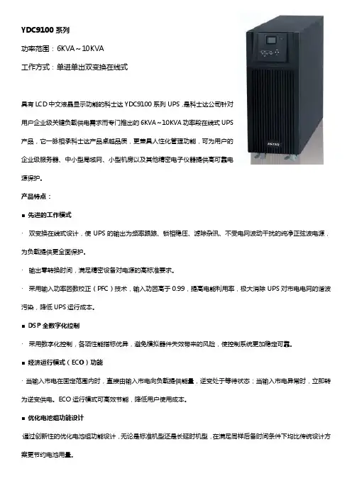
YDC9100系列功率范围:6KVA~10KVA工作方式:单进单出双变换在线式具有LCD中文液晶显示功能的科士达YDC9100系列UPS,是科士达公司针对用户企业级关键负载供电需求而专门推出的6KVA~10KVA功率段在线式UPS产品,它一脉相承科士达产品卓越品质,更兼具人性化管理功能,可为用户的企业级服务器、中小型局域网、小型机房以及其他精密电子仪器提供高可靠电源保护。
产品特点:■ 先进的工作模式· 双变换在线式设计,使UPS的输出为频率跟踪、锁相稳压、滤除杂讯、不受电网波动干扰的纯净正弦波电源,为负载提供更全面保护。
· 输出零转换时间,满足精密设备对电源的高标准要求。
· 采用输入功率因数校正(PFC)技术,输入功因高于0.99,提高电能利用率,极大消除UPS对市电电网的谐波污染,降低UPS运行成本。
■ DSP全数字化控制· 采用数字化控制,各项性能指标优异,避免模拟器件失效带来的风险,使控制系统更加稳定可靠。
■ 经济运行模式(ECO)功能· 当输入市电在固定范围内时,直接由输入市电向负载提供能量,逆变处于等待状态;当输入市电异常时,立即转为逆变供电。
ECO运行模式可高效节能,降低用户使用成本。
■ 优化电池组功能设计·通过创新性的优化电池组功能设计,无论是标准机型还是长延时机型,在满足同样后备时间条件下均比传统设计方案更节约电池用量。
■ 环境适应性强· 宽广的输入电压范围,避免电网电压变化大时频繁地切换至电池供电,适应于电力环境恶劣的地区。
· 宽输入频率范围,保证接入各种燃油发电机均可稳定工作,满足用户对油机使用的要求。
可靠的保护功能· 具有开机自诊断功能,可及时发现UPS的隐性故障,防患于未然。
· 具有输入过欠压保护,输出过流、过载、短路保护· PFC及逆变器过热保护,电池过充及欠压预警保护等多种保护,保证系统运行的稳定性和可靠性。
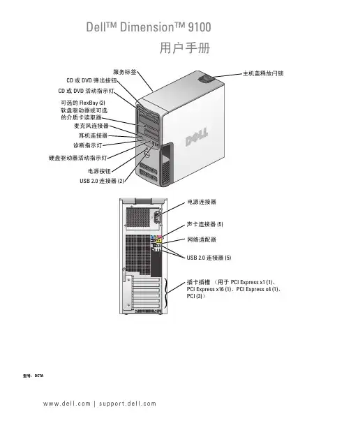
w w w.d e l l.c o m | s u p p o r t.d e l l.c o mDell™ Dimension™ 9100可选的 CD 或 DVD CD 或 DVD 、、型号:DCTA注、注意和警告注:注表示可以帮助您更好地使用计算机的重要信息。
注意:注意表示可能会损坏硬件或导致数据丢失,并告诉您如何避免此类问题。
警告:警告表示可能会导致财产损失、人身伤害甚至死亡。
如果您购买的是 Dell™ n Series 计算机,则本说明文件中有关 Microsoft® Windows®操作系统的所有参考信息均不适用。
____________________本说明文件中的信息如有更改,恕不另行通知。
©2005Dell Inc.。
版权所有,翻印必究。
未经 Dell Inc.书面许可,严禁以任何形式进行复制。
本文中使用的商标:Dell、DELL徽标、Inspiron、Dell Precision、Dimension、OptiPlex、Latitude、PowerEdge、PowerVault、PowerApp、DellNet和PowerConnect 是 Dell Inc. 的商标;Intel、Pentium 和Intel SpeedStep是 Intel Corporation 的注册商标;Microsoft、Windows和Outlook是 Microsoft Corporation 的注册商标。
本说明文件中述及的其它商标和产品名称是指拥有相应商标和产品名称的公司或其制造的产品。
Dell Inc. 对其它公司的商标和产品名称不拥有任何所有权。
型号:DCTA2005 年 10 月P/N D8664Rev. A01目录查找信息 (9)1设置和使用计算机设置打印机 (13)打印机电缆 (13)连接 USB 打印机 (14)连接至 Internet (14)设置 Internet 连接 (15)播放 CD 和 DVD (16)调节音量 (17)调整图片 (18)复制 CD 和 DVD (18)如何复制 CD 或 DVD (18)使用空白 CD 和 DVD (19)注意事项 (20)使用介质卡读取器(可选) (21)连接两台显示器 (22)连接两台配备 VGA 连接器的显示器 (22)连接一台配备 VGA 连接器的显示器和一台配备 DVI 连接器的显示器 (23)连接电视 (24)更改显示设置 (24)设置家庭和办公网络 (25)连接网络适配器 (25)网络安装向导 (25)电源管理 (26)待机模式 (26)休眠模式 (26)电源选项属性 (27)目录3IEEE 1394 (28)超线程 (29)2解决问题故障排除提示 (31)电池问题 (31)驱动器问题 (32)CD 和 DVD 驱动器问题 (32)硬盘驱动器问题 (33)电子邮件、调制解调器和 Internet 问题 (33)错误信息 (35)介质卡读取器问题 (36)键盘问题 (36)锁定和软件问题 (37)计算机无法启动 (37)计算机停止响应 (37)程序停止响应 (37)程序多次崩溃 (37)程序设计为用于早期版本的 Windows 操作系统 (38)出现蓝屏 (38)其它软件问题 (38)内存问题 (39)鼠标问题 (39)网络问题 (40)电源问题 (40)打印机问题 (41)扫描仪问题 (42)声音和扬声器问题 (42)扬声器没有声音 (43)耳机没有声音 (43)4目录视频和显示器问题 (43)如果屏幕为黑屏 (44)如果屏幕显示不清楚 (44)3故障排除工具诊断指示灯 (45)Dell 诊断程序 (48)Dell 诊断程序主菜单 (48)驱动程序 (49)什么是驱动程序? (49)识别驱动程序 (50)重新安装驱动程序 (50)解决软件与硬件不兼容的问题 (51)还原操作系统 (52)使用 Microsoft Windows XP 系统还原 (52)撤消上次系统还原 (53)使用 Symantec 提供的 Dell PC Restore (54)4卸下和安装部件开始之前 (57)建议工具 (57)关闭计算机电源 (57)拆装计算机内部组件之前 (58)计算机的正面视图 (59)计算机的背面视图 (61)卸下主机盖 (62)计算机内部视图 (64)系统板组件 (65)内存 (66)内存概览 (66)安装内存 (68)卸下内存 (70)目录5插卡 (70)PCI 卡 (70)PCI Express 卡 (75)驱动器面板 (83)卸下驱动器面板 (83)卸下驱动器面板插件 (84)装回驱动器面板插件 (85)装回驱动器面板 (85)驱动器 (86)一般安装原则 (86)硬盘驱动器 (87)卸下硬盘驱动器 (88)安装硬盘驱动器 (89)添加第二个硬盘驱动器 (90)软盘驱动器 (92)卸下软盘驱动器 (92)安装软盘驱动器 (94)介质卡读取器 (94)卸下介质卡读取器 (94)安装介质卡读取器 (96)CD/DVD 驱动器 (98)卸下 CD/DVD 驱动器 (99)安装 CD/DVD 驱动器 (100)电池 (102)更换电池 (102)装回主机盖 (103)5附录规格 (105)系统设置程序 (109)概览 (109)进入系统设置程序 (110)系统设置程序选项 (111)“Boot Sequence”(引导顺序) (114)6目录清除已忘记的密码 (115)清除 CMOS 设置 (116)清洁计算机 (116)计算机、键盘和显示器 (116)鼠标 (117)软盘驱动器 (117)CD 和 DVD (117)与 Dell 联络 (118)索引 (135)目录78目录查找信息要查找什么?在此处查找Dell™ 产品信息指南•保修信息•条款和条件(仅限于美国)Array•安全说明•管制信息•人机工程学信息•最终用户许可协议注:可以从获得本说明文件的 PDF文件。
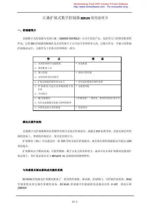
江森扩展式数字控制器DX9100使用说明书一、控制器简介直接数字式控制器为美国江森(JOHNSON CONTROLS)公司开发的产品,包括其专门的图形配置软 件包,它将DDC控制器的精确性及灵活性集中于小巧而可管理的单元内,它既可作为一个独立的智能 控制器而运行,又能作为上位机自控网络的一部分。
特 点 效 益- 容易配置△ 内置控制程序功能模块△ 图形配置工具△ 独立控制- 系统可靠性强△ 实时时钟及时间程序△ 扩展总线提供额外的I/O点 - 多用途的模块化硬件设置△ 扩展模块可适应各种模拟数字的- 安装费用低I/O△ 不同组合△ N2总线通讯- 控制设备广、效率高、费用经济的信息共享 △ 具有动态数据存取能力的网络软件△ 内置状态显示及控制盘 - 容易使用模块化硬件结构直接数字式控制器模块化的硬件结构可安装在控制盘内,或通过DIN标准导轨,直接安装在所控 制的设备上。
坚固的结构设计,使其更具吸引力。
扩展模块(XTs)可以透过同一条 DIN 导轨安装在控制器旁,或安装在离控制器最远不超过1200 米的地方。
扩展模块由子模块组成,可提供模拟、数字I/O点的各种组合。
最多可有8块扩展模块连接到扩 展总线上,其扩展总线具有与METASYS N2总线相同的物理特性。
与传感器及驱动器构成完整的系统DX-9100控制器及扩展模块配备了一系列的传感器、驱动器、控制阀门,可控制冷冻机组、HVAC 空调系统及其它制冷采暖的设备。
DX-9100控制器不但能接收变送器送出的 0-10V 的电压和JOHNSONCONTROLS无源温度传感器所输出的信号,也能接收工业标准的4-20mA信号。
控制的输出,不但能控 制比例式及增量式电子驱动器,也能分段加热制冷及其它一些电气设备。
方便的结构配置控制器无需按传统的方式编程,而是用图形编程软件对控制算法、时间程序和输入输出点的分配 进行设置。
图形编程软件是在与控制器的 N2总线相连的计算机上运行,从简化了控制器的配置。
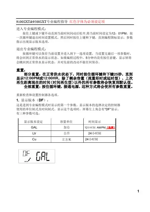
9100SXT&9500SXT专业编程指导红色字体为必须设定项进入专业编程模式:按住上键或下键不动直到当前时间闪动后松开,将当前时间设定为12:01PM,按一次循环键退出时间设置模式。
然后同时按住上键和下键,直到编程图标显示,参数指示出现显示版本选项。
退出专业编程模式:按循环键可以保存当前设置并进入到下一选项设置,当设置完最后一项参数时,将会回到正常供水的显示状态。
如果编程过程中,5分钟内没有按任意键,显示屏将会跳回到正常供水显示状态,并对先前的改动不做任何保存。
重置:部分重置:在正常供水状态下,同时按住循环键和下键25秒,直到显示12:00PM或12:00HR,除了剩余容量(流量即时或延时型)、上次再生距离现在的时间(时间再生型)以外的所有参数将会恢复到默认值。
全部重置:按住循环键,接通电源,这种方式将会使所有参数重置。
重新检查和设置控制器各选项。
1.显示版本(DF):这是进到专业编程模式时显示的第一个参数。
显示版本的选择决定的控制器使用的单位制式及时间制式。
显示这个选项时,屏幕左上角会有"DF"显示。
有三种参数可选。
显示版本设定GALLtrCu 容量单位加仑公升立方米时间显示12小时制AM/PM(选择)24小时制24小时制1专业编程指导2. 阀门类型(VT ): 程。
注意设定之前先确定使用的阀门类型。
显示此选项时,屏幕左上角显示 "VT",有5种参数可选。
按循环键将进入到阀门类型的显示。
此选项用来设定阀门再生时的流向及过 参数 标准的顺流/逆流再生,一次反洗 (选择项) 标准的顺流/逆流再生,二次反洗 过滤 逆流再生先吸盐 其它缩写St1bSt2bFltrUFbFOthr 3. 控制类型(CT ):按循环键,进入到控制类型的显示。
此选项用来设定阀门由何种方式引发再生。
关于如何选择,请参考本说明书"控制器功能"一节。
显示此选项时,屏幕左上角显示"CT",有4种参数可选。
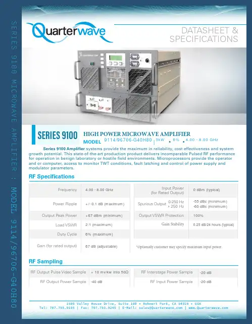
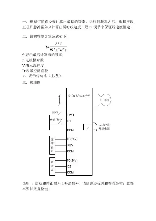
Frequency Power Ripple Duty CycleGain (for rated output)Output Peak PowerLoad VSWR RF SamplingRF Output Pulse Video SampleRF Output Power SampleRF Interstage Power SampleRF Input Power SampleInput Power (for Rated Output )Spurious Output0-250 Hz> 250 Hz Output VSWR ProtectionGain Stability*Optionally customer may specify maximum input power.4.00 - 8.00 GHz 0 dBm (typical)+/- 0.1 dB (maximum)-55 dBc (minimum)-60 dBc (minimum)+67 dBm (minimum)100%2:1 (maximum)0.25 dB/24 hours (typical)6% (maximum)67 dB (adjustable)+ 10 mv/kw into 50Ω-20 dB -40 dB-20 dBMODEL 9114/96706-G40H80EnvironmentalOperating Temperature Storage TemperatureHumidity AltitudeCoolingRS-232 interface provides ability to remotely operate, monitor, control and adjust thesystem. IEEE-488, an optional feature, provides the ability to remotely operate, monitor and control operation of the amplifier. Any fault condition latches information. Ethernet (LAN) and RS-422 are also available. Software is provided to operate with MS Windows.DIGITAL INTERFACE RS-232Self Contained Forced Air0.1 to +50C | Derate to 10C for 10,000 foot Operation -40 to +85C0 to 95% non-condensing0 to 10,000 feet above sea level, 50,000 non-operatingMODEL 9114/96706-G40H80CONNECTORSTYPERF Input (Rear Panel )RF Output (Rear Panel )RF Samples (Front Panel )RF Output Pulse Video Sample (Front Panel )Modulation Input Panel (Front Panel )FRONT PANEL : Switches: Illuminated Status Monitor : Off/Standby /Operate /Reset: Warm-up /Standby /Operate /ResetACCESSORIES SUPPLIED 1-EACH •Maintenance Manual•Primary Input Power Mating Connector •CD ROM: Computing Operating SoftwareCONTROLS & INDICATORSCo-ax | Type "NF"Waveguide | WRD-350Co-ax | Type "NF"Co-ax | Type "BNCF"Co-ax | Type "BNCF"MODEL 9114/96706-G40H80MODEL 9114/96706-G40H80。
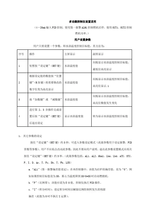
多功能控制仪设置说明(4-20mA输入PID控制,使用第一报警ALM1控制燃机启停,使用OUT1、OUT2控制燃机功率。
)用户设置参数用户只需设置一个参数,即水浴温度控制目标值,其方法为:1、其它参数的设定按住“设定键”(SET键)约3秒,可进入参数设定模式(此级参数用于设定报警,PID 常数等参数)。
用户不应私自改动此参数,因此不要向用户说明。
退出此参数设置模式应再次按住“设定键”(SET键)约3秒。
(此级参数包括:AL1、AL2、HbA1、LbA、Lbd、ATU、STU、P、I、D、Ar、T、Pc、Db、T、Pb、LCK)a.“AL1”(第一报警偏差值设定):在本控制器中,该值为启炉的偏差值,设为“0”。
例如如果控制目标值设为80,那么当温度降到80-0=80时启动燃烧机。
b.“P”(比例带):该值应设为非0值,控制仪执行PID操作。
c.“I”(积分时间):设定积分时间以解除比例控制所发生的残留偏差(此值为0时不执行I运算)。
d.“D”(微分时间):设定微分时间以防止输出的波动提高控制安定(此值为0不执行D运算)。
注:如果燃机采用两段火工作方式应将P值设为0,此时仪表不执行PID运算。
上述三个参数“P”“I”“D”的设定值应根据现场实际经验设定或启自动演算。
e. “T”比例周期:设定加热侧比例周期(即动作周期)数值范围1-100,不能为零值。
“T”越小OUT1动作越频繁。
f. “Pc”比例带(制冷侧):数值范围1-1000,设置制冷侧比例带(控制OUT2闪烁输出关断时间),“Pc”越大关断时间越长。
g. “t”比例周期(制冷侧):数值范围1-100,设置制冷侧输出周期,“t”越小OUT2动作越频繁。
注:“P”、“I”、“D”、“T”、“t”配合调节控制OUT1、OUT2输出频率和接通关断时间。
h. “LCK”数据禁锁功能:在所有参数设置完毕后,应将该参数设为“0011”,即只有水浴温度控制目标值(SV)可以设定。
软化水使用手册9100 sevice manual 软化水使用手册9100 Service Manual1.产品概述1.1 产品描述1.2 产品特点1.3 技术规格1.4 安全注意事项2.安装2.1 准备工作2.2 安装步骤2.3 连接管路2.4 电源接线2.5 启动调试3.操作与维护3.1 操作说明3.2 加盐操作3.3 出水设置3.4 故障排除3.5 日常维护3.6 清洗与保养4.高级功能4.1 自动控制功能4.2 远程监控与控制4.3 数据记录与报表5.常见问题解答5.1 加盐周期过长怎么办?5.2 水质不达标怎么处理?5.3 如何调整出水硬度?5.4 如何清理过滤芯?附件:附件1、电路图附加2:部件清单法律名词及注释:1.合同条款:合同中的法律规定,双方在订立合同时需遵守和执行的法律条款。
2.免责声明:声明一方免除或减少法律责任的声明。
3.违约责任:因合同不履行或违反合同而应承担的法律责任。
4.知识产权:指由人的智力创造性劳动创造出来的智慧财产,包括专利权、著作权、商标权等。
5.保密协议:订立双方在涉及商业敏感信息时,就信息的保密和使用事宜达成的协议。
附件:附件1:电路图附件2:部件清单法律名词及注释:1.合同条款:合同中的法律规定,双方在订立合同时需遵守和执行的法律条款。
2.免责声明:声明一方免除或减少法律责任的声明。
3.违约责任:因合同不履行或违反合同而应承担的法律责任。
4.知识产权:指由人的智力创造性劳动创造出来的智慧财产,包括专利权、著作权、商标权等。
5.保密协议:订立双方在涉及商业敏感信息时,就信息的保密和使用事宜达成的协议。

PD9100 / 9200 SERIES POWER CONVERTERin material or workmanship under normal use and service; and limits the remedies to repair or This warranty shall extend for a period of two years from the original date of purchase, is valid only within the continental limits of the United States and Canada.WARRANTY EXCLUSIONS: This warranty specifically does not apply to:Any power converter which has been repaired or altered in any way by an unauthorized person orDamage caused by excessive input voltage, misuse, negligence or accident; or an external force;Any power converter which has been connected, installed or adjusted or used other than in accordance the instructions furnished, or has had the serial number altered, defaced or removed;Cost of all services performed in removing and re-installing the power converter; andANY LOST PROFITS, LOST SAVINGS, LOSS OF USE OF ENJOYMENT OR OTHERDAMAGES ARISING OUT OF THE USE OF, OR INABILITY TO USE, THEINCLUDES DAMAGES TO PROPERTY AND, TO THE EXTENT PERMITTED BY LAW, DAMAGES FOR PERSONAL INJURY. THIS WARRANTY IS IN LIEU OF ALL OTHER WARRANTIES, INCLUDING IMPLIED WARRANTIES OFMERCHANTABILITY AND FITNESS FOR A PARTICULAR PURPOSE.PROOF OF PURCHASE: A warranty claim must be accompanied by proof of the date of purchase.CLAIM PROCEDURE: Upon discovery of any defect, Progressive Dynamics, Inc. shall be suppliedthe following information at the address listed below: and address of the claimant;, model and serial number of the power converter;C.Application in which the power converter was installed. (Includes manufacturer,model and model year where applicable)D.Date of purchase; andplete description of the claimed defect.Upon determination that a warranty claimoccurring under normal use and service,)prepaid to Progressive Dynamics, Inc. togetherconverter will be repaired or replaced and returned postage prepaid.Extended warranties areavailable for purchase atINSTALLATION INSTRUCTIONSNOTES:•Horizontal mounting of the power converter, isrecommended although it can be mounted in any position that provides unobstructed ventilation to the fan and vent holes.•The OEM should test the power converter underfull load conditions in its intended mountinglocation. This will insure that there is sufficientunobstructed ventilation to the converterallowing it to operate at its maximum rated load.Failure to provide adequate ventilation to theconverter will cause the converter output to bereduced as it responds to ambient conditions.•The INTELI-POWER converters are notdesigned for zero clearance compartments. •Use a 5/32” hex driver to tighten the outputscrews. Do not exceed 50 in-lbs. torque on the output terminals.•The INTELI-POWER converters are not weather tight or designed for wet mounting locations.They must be protected from direct contact with water.•Avoid the introduction of foreign materials intothe case as this could damage or cause amalfunction of the converter. Installation Steps:1.Secure converter firmly to mounting surface.2.Connect ground lug (found on unit base) tochassis.•Ground wire to be between 6 and 12AWG wire.•Tighten lug to 25 – 35 in-lbs.3.Disconnect battery from both positive (+) andground (-) cables.4.Connect battery ground (-) to converter NEG (-)lug.•Conductor to be between 2 and 14AWG(follow all applicable codes when sizingconductor)•Tighten lug to 30 – 50 in-lbs.5.Disconnect any optional pendants or modules.6.Plug converter into appropriate outlet.ing a DC voltmeter, verify converter output.The power converter is working properly if thevoltage is above 13VDC (12V models), 26VDC(24V models, 14.3VDC (12V 9100L models),and 28.4VDC (24V 9100-24L models). If nooutput is present, refer to the trouble shooting guide in this manual.8.Disconnect power to converter9.Connect battery positive (+) to converter POS (+)lug.•Conductor to be between 2 and 14AWG(follow all applicable codes when sizingconductor)•Tighten lug to 30 – 50 in-lbs.Note: When connecting battery to converterPOS (+), a spark may occur. This is normal. 10.Reconnect battery to both positive (+) and ground(-) cables.11.Reconnect any optional pendants or modules.12.Reconnect power to converter.GENERAL INFORMATIONThe INTELI-POWER series power converters are state-of-the-art electronic converter / battery chargers.Their compact size and quiet operation gives greater flexibility in selecting the mounting location for either OEM installation or after market replacement.All INTELI-POWER series power converters have been designed and tested to provide maintenance free operation and undergone tens of thousands of hours of strenuous engineering testing to ensure years of trouble free operation.The INTELI-POWER 9200 series converter incorporates the Charge Wizard® microprocessor which constantly monitors the battery voltage and automatically adjusts the converter output voltage to provide the proper charging voltage for fast recharges and long-term maintenance.INTELI-POWER 9100 series converters incorporate the Total Charging Management System (TCMS) interface. The TCMS interface connects the converter to optional devices that can automatically control the output voltage of the converter thereby controlling the charge rate to the batteries. (See below for ChargeW izard® functions and performance)INTELI-POWER 9100L series converters do NOT support the Charge Wizard® functionality or provide a TCMS interface. The 9100L series converters incorporate an interface for a remote shutdown module for use with a smart lithium battery system.FEATURESMULTIPLE BATTERY CHARGING... INTELI- POWER converters have the capability of charging multiple batteries at the same time! They can even charge a combination of different capacity batteries. GFCI PROTECTION... INTELI-POWER converters have the LOWEST ground fault leakage. With this unit, the user can confidently utilize theRV's AC outlets without being concerned about a ground fault interruption of the facilities power source.REVERSE BATTERY PROTECTION prevents damage if battery leads are cross connected. Since the only consequence of cross connection is a blown fuse, damage to or possible replacement of the converter is avoided. Cross connection of battery leads is the only thing that will blow these fuses. Replacement fuses are available at any automotive store.CAUTIONIF THE REVERSE BATTERYPROTECTION FUSES ARE BLOWN DURING INSTALLATION, CHECK TOSEE THAT THE BATTERY HAS BEENCONNECTED PROPERLY BEFORE REPLACING THE FUSES. REPLACE THE FUSES ONLY WITH THE SAME TYPE AND RATING AS THE ORIGINAL FUSES. USING OTHER FUSES MAY RESULT IN CONVERTER DAMAGE, VEHICLEDAMAGE, INJURY OR OTHERCONSEQUENCES (SEE WARRANTY). ELECTRONIC CURRENT LIMITING... Should demand exceed the rated capacity of the converter or a short circuit occur, the output voltage of the converter drops to almost zero until the situation is corrected. This feature prevents blown fuses, damage to the converter, 12 volt motors and wiring. AUTOMATIC THERMAL PROTECTION... Should an over temperature condition occur, the converter will reduce power output. The converter automatically resumes normal operation when a safe operating temperature is reached.IGNITION PROTECTION... All INTELI-POWER series converters are ignition protected. VARIABLE SPEED COOLING FAN... An electronic sensor monitors converter temperature. Higher demand generates higher heat, requiring higher fan speeds. Lower demand means lower heat and fan speed. This means the fan may not operate at night or will operate at a very slow, quiet speed when demand is low and the owner is trying to sleep. HIGH VOLTAGE PROTECTION... This circuit shuts the converter down if a surge or spike in input voltage is detected. The converter will automatically return to normal operation when the condition is corrected.LOW VOLTAGE PROTECTION…INTELI-POWER converters automatically shut down if input voltage is insufficient for continued operation. When the low voltage situation is corrected, the INTELI-POWER converter automatically resumes normal operation.GENERAL OPERATIONThe INTELI-POWER series converter will supply "clean" power from input voltages that range from 90-130 VAC (205-265 VAC for 230 volt models). The INTELI-POWER series of converters are primarily designed for use with a battery, however, the output of the INTELI-POWER converters are a regulated, filtered DC voltage that can power sensitive electronics without the need for a battery or other filtering.At normal input voltages the full load rated capacity is available.At input voltages less than 105 VAC (205 VAC for 230 volt models) the converter may not supply full rated output capacity.9100L - The full rated load is available for load, battery charging or both. When functioning as a regulated battery charger the converter has a nominal voltage output of 14.6 VDC for 12 volt models and 29.2 VDC for 24 volt models. The system is designed to sense voltage on the battery and will taper the charging current as the battery becomes charged.CAUTIONThe 9100L series converter/chargers aredesigned to recharge lithium ironphosphate batteries.DO NOT USE TO RECHARGELEAD/ACID BATTERIES!9100 - The full rated load is available for load, battery charging or both. When functioning as a regulated battery charger the converter has a nominal voltage output of 13.6 VDC for 12 volt models and 27.2 VDC for 24 volt models. The system is designed to sense voltage on the battery and will taper the charging current as the battery becomes charged.When the vehicle is to be stored for extended periods of time it is recommended that the batteries be disconnected, unless a TCMS Charge Wizard® is attached to the TCMS interface. Reconnect battery once a month to maintain a full charge. 9200 - The full rated load is available for load, battery charging or both. When functioning as a regulated battery charger the converter has a nominal voltage output of 13.6 VDC for 12 volt models and 27.2 VDC for 24 volt models. The system is designed to sense voltage on the battery and automatically selects one of three operating modes (normal, boost and storage) to provide the correct charge level to the batteries. BOOST MODE: If the converter senses that the battery voltage has dropped below a preset level the output voltage is increased to approximately 14.4 VDC (28.8 VDC for 24 volt models) to rapidly recharge the battery.NORMAL MODE: Output voltage set at approximately 13.6 VDC (27.2 VDC for 24 volt models).STORAGE MODE: When the converter senses that there has been no significant battery usage for 30 hours the output voltage is reduced to 13.2 VDC (26.4 VDC for 24 volt models) for minimal water usage. When in storage mode the microprocessor automatically increases the output voltage to 14.4 VDC (28.8 DC for 24 volt models) for approximately 15 minutes every 21 hours to help prevent sulfation of the battery plates.CAUTIONIT IS IMPORTANT THAT THE FLUIDLEVEL OF ANY CONNECTEDBATTERIES BE CHECKED ON AREGULAR BASIS. ALL BATTERIESWILL “GAS” AND LOSE SOME FLUIDS WHEN CONTINUOUSLY CONNECTED TO ANY CHARGING SOURCECHARGE WIZARD ®… The INTELI-POWER 9200 series converters have the Charge Wizard ® controlledcharging module built in. The Charge Wizard ® is a microprocessor-controlled device incorporated in Progressive Dynamics 9200 Series INTELI-POWER converters which constantly monitors the battery, and automatically adjusts the converter output voltage based on its charge status. The Charge Wizard ® has four (4) operating modes (BOOST, NORMAL, STORAGE and EQUALIZE). Each mode is automatically selected by the Charge Wizard ® and ensures a fast yet safe recharge for your battery. See chart below for details.NOTE: Converter output voltages are 2x the values listed in above table for 24 volt models.Boost Mode (14.4V for 12V models and 28.8V for 24V models) - Boost mode is to rapidly recharge a battery up to 90% of full charge. Required 8 hours to return the battery to 90% of full charge and approximately 11 hours to reach full charge.**Normal Mode (13.6V for 12V models and 27.2V for 24V models) - Normal mode is to safely complete the charge of a battery. Required 40 hours to return the battery to 90% of full charge and approximately 78 hours to reach full charge.**Storage Mode (13.2V for 12V models and 26.4V for 24V models) – Storage mode is to maintain a batteries charge as well as help prevent battery stratification and sulfation. Required 60 hours to return the battery to 90% of full charge and approximately 100 hours to reach full charge.**Equalize Mode (14.4V for 12V models and 28.8V for 24V models) - The Charge Wizard ® will automatically switch to equalize mode for approximately 15 minutes every 21 hours the converter remains in storage mode. This will help prevent battery stratification, sulfation and loss of battery capacity (useful life).** Times based on a PD9155 recharging a 125AH battery that has been discharged to 10.5V.- All times and voltages provided above are approximate. -The integrated Charge Wizard’s ability to change the output voltage of the converter will significantly reduce the amount of time it takes to recharge your battery. The lower voltage for Storage mode helps prevents gassing and reduces water loss during long-term storage.BOOST MODENORMAL MODESTORAGE MODEEQUALIZE MODEOPTIONAL REMOTE PENDANTYour INTELI-POWER 9200 converter may have been supplied with a Remote Pendant. The Remote Pendant is optional on OEM but is included with all retail models and plugs in to the accessory port of the 9200 series converter. While the built-in Charge Wizard® automatically determines which operating mode is best suited to recharge or maintain optimum battery condition, the Remote Pendant allows for manual override and has an indicator light to indicate the mode of operation.BOOST MODE - Indicated by green LED remaining on.NORMAL MODE - When the battery is between 50% and 90% charged, the green LED will flash once per second. When the battery has reached 90% of full charge the green LED will flash 2 - 3 times per second.STORAGE MODE - Indicated by green LED flashing every 6 - 8 seconds.MANUAL BUTTON - The manual button has been provided to allow the operator to temporarily override the converter (not recommended) or to verify the converter is operating properly. For manual operation, press and hold the button. The indicator light will soon remain “ON” indicating Boost Mode. Continue to hold the button and the light will blink rapidly indicating the converter is in the Normal Mode. Continue to hold the button until the light blinks slowly indicating the converter is now in the Storage Mode. After the manual button is released the converter will stay in the selected mode. When the battery charge status changes, the converter will return to the automatic mode of operation to prevent damage to the battery.If a REMOTE PENDANT was not provided with your INTELI-POWER 9200 Series converter, you can purchase one from your local RV dealer or online at OPTIONAL TCMS CHARGE WIZARD Your INTELI-POWER 9100 converter is equipped with a TCMS interface. The TCMS Charge Wizard pendant plugs into the TCMS interface to provide computer control and monitoring of your batteries charge state. The Charge Wizard® automatically determines which operating mode is best suited to recharge or maintain optimum battery condition. The Charge Wizard®Pendant allows for manual override and has an indicator light to indicate the mode of operation.BOOST MODE - Indicated by green LED remaining on.NORMAL MODE - When the battery is between 50% and 90% charged, the green LED will flash once per second. When the battery has reached 90% of full charge the green LED will flash 2 - 3 times per second.STORAGE MODE - Indicated by green LED flashing every 6 - 8 seconds.MANUAL BUTTON - The manual button has been provided to allow the operator to temporarily override the converter (not recommended) or to verify the converter is operating properly. For manual operation, press and hold the button. The indicator light will soon remain “ON” indicating Boost Mode. Continue to hold the button and the light will blink rapidly indicating the converter is in the Normal Mode. Continue to hold the button until the light blinks slowly indicating the converter is now in the Storage Mode. After the manual button is released the converter will stay in the selected mode. When the battery charge status changes, the converter will return to the automatic mode of operation to prevent damage to the battery.The TCMS Charge Wizard Pendant can be purchased from your local RV dealer or online atOPTIONAL REMOTE SHUTDOWN MODULE Your INTELI-POWER 9100L converter is equipped with a Remote Shutdown Module interface. The converter can be shutdown using either a high or low side control, or by connecting two wires by means of a mechanical switch or relay contacts. This allows the battery management system to shutdown the converter after battery charging and balancing are complete.Do not replace the converter unless the following checks have been performed:Loosen the screw on the positive terminal and disconnect the positive wire. Read the converter output voltage using aDC voltmeter. The power converter is working properly if the voltage is above 13VDC (12V models), 26VDC (24V models, 14.3VDC (12V 9100L models), and 28.4VDC (24V 9100-24L models).If the converter output is zero volts, use an AC voltmeter to check for proper voltage at the 120VAC outlet that theconverter is plugged into. This voltage should be between 105 and 130 volts (206 and 265 volts for 230V models). Check the fuses located at the front of the converter. These fuses will only blow if the battery or DC output leadswere connected in reverse, even for a moment. Replace the fuses and repeat step 1.Disconnect optional Remote Pendant, TCMS Charge Wizard, or Remote Shutdown Module. output voltage using a DC voltmeter. The power converter is working properly if the voltage is above 13VDC (12V models), 26VDC (24V models, 14.3VDC (12V 9100L models), and 28.4VDC (24V 9100-24L models). When replacing fuse(s) it may be necessary to remove the TCMS plug or lithium shutdown module (if so equipped)to provide clearance for fuse replacement.Disconnect all power sources before replacing fuses.TROUBLE SHOOTING GUIDEPROBLEMPOSSIBLE CAUSESACTION1. No OutputProper AC power not connected Connect power supplyCheck AC distribution panel for proper operation External Fuses Blown Check for reverse polarityReplace fuses with same type and rating Short CircuitTrace circuits for possible fault Unit has shutdown due to overheating Check air flow Allow unit to cool Unit has shutdown due to over voltage (Also see Item 4 below)(No over voltage protection for 230V units) Check input voltageConverter will shut down if the input voltage exceeds 132 Volts Correct input voltageOptional remote shutdown module is active. (PD9100L only)Remove remote shutdown module.2. External Fuses Blown Reverse Battery Hook Up Correct hook up and replace fuses with same type and rating3. Low OutputExcessive load for converterReduce load requirements or install larger converter Input voltage not between 105-130 VAC (205-265 VAC for 230V units) Correct input supply voltage Bad battery cell(s)Replace battery4. Intermittent or no Output on Generator, works on Shore PowerUnit has shutdown due to over voltage. Add another load to the generator, this may reduce the “spikes” to an acceptable levelSome generators exhibit excessive voltage spikes on the AC power output, this may cause the over voltage protection to shut the unit downContact generator manufacturer for possible defect in the generatorRemote Shutdown Module does not have stable voltage.Confirm Remote Shutdown Module voltage is between 5 and 30 VDCAccessory Port (PD9200only)DC Distribution PanelGrounding Lug (located on AC end) Reverse BatteryFuse(s)-+Chassis Ground BatteryINPUT/OUTPUT S PECIFICATIONS (Specifications subject to change without notice)PD9130(L)Input: 105-130 VAC 60 Hz500 WattsOutput: 13.6 VDC, 30 Amps (9130L) – 14.6 VDC, 30 Amps Dimensions: 4.5H x 8.25L x 7.25WWeight: 4.5lbsPD9140(L)Input: 105-130 VAC 60 Hz600 WattsOutput: 13.6 VDC, 40 Amps (9140L) – 14.6 VDC, 40 Amps Dimensions: 4.5H x 8.25L x 7.25WWeight: 4.5lbsPD9_45(L)Input: 105-130 VAC 60 Hz725 WattsOutput: 13.6 VDC, 45 Amps (9145L) – 14.6 VDC, 45 Amps Dimensions: 4.5H x 8.25L x 7.25WWeight: 4.5lbsPD9_60(L)Input: 105-130 VAC 60 Hz1000 WattsOutput: 13.6 VDC, 60 Amps (9160L) – 14.6 VDC, 60 Amps Dimensions: 3.6H x 8L x 9WWeight: 5.8lbsPD9_70(L)Input: 105-130 VAC 60 Hz1250 WattsOutput: 13.6 VDC, 70 Amps (9170L) – 14.6 VDC, 70 Amps Dimensions: 3.6H x 8L x 9WWeight: 5.8lbsPD9_80A(L)Input: 105-130 VAC 60 Hz1300 WattsOutput: 13.6 VDC, 80 Amps (9180AL) – 14.6 VDC, 80 Amps Dimensions: 3.6H x 8L x 9WWeight: 6.0lbsPD9_25-24(L)Input: 105-130 VAC 60 Hz775 WattsOutput: 27.2 VDC, 25 Amps (9125-24L) – 29.2 VDC, 25 Amps Dimensions: 4.5H x 8.25L x 7.25WWeight: 4.5lbs PD9_40-24A(L)Input: 105-130 VAC 60 Hz1300 WattsOutput: 27.2 VDC, 40 Amps (9140-24AL) – 29.2 VDC, 40 Amps Dimensions: 3.6H x 8L x 9WWeight: 6.0lbsPD9260-230Input: 205-265 VAC 50/60 Hz1000 WattsOutput: 13.6 VDC, 60 Amps Dimensions: 3.6H x 8L x 9WWeight: 5.8lbsNOT UL OR CUL LISTED。
kty-9100仪表说明书
1、修改仪表一级参数“CLK=132”,打开程序密码锁。
在仪表显示状态下按SET键,仪表转入控制参数设定状态。
每按SET键仪表按照顺序变换一级参数(一次巡回后即回至最初项目),将参数符号“CLK”后出现的数字用“上”键或“下”键修改为“132”。
2、进入仪表二级参数,依次修改“SL0(输入信号类型)”、OUL (变送输出下限值,数值与SLL一致)、OUH(变送输出上限值,数值与SLH一致)、SLL(仪表量程下限)、SLH(仪表量程上限)。
在设定CLK=132后,在PV显示器显示CLK设定值(132)状态下,同时按下“SET”键和“上”键约30秒,仪表即进入二级参数设定。
每按SET键仪表按照顺序变换二级参数(一次巡回后即回至最初项目)。
3、按压SET键出现下一个参数符号时即将刚才的修改自动保存至芯片
4、按仪表复位键或让仪表自行退出参数设定状态,仪表回复显示。
UPS电源YDC9100系列YDC9100系列UPS可为用户提供数据中心、关键负载提供稳定的电力环境和可靠的电源保护,满足用户对UPS的高可靠性要求。
具备自动调节升降压功能,电源自检功能,为用户安全可靠的电源保护。
产品核心卖点1.质量稳定,市场保有量超过30万台。
2.整机最高效率96%,高于同类产品两个百分点。
3.:输入电压范围(115~295VAC),适应于电网波动大的场合。
4.输出功因0.8/0.9,比同行同类产品带载能力强。
5.并机可共用电池组,电池电压可选配(16/18/20节)。
6.可根据电池容量的改变,自动调整充电电流,延长电池使用寿命。
7.并机通讯冗余,保障并机稳定运行。
技术参数型号YDC9101S/H/H-BYDC9102S/H/H-BYDC9103S/H/H-BYDC9106S/HYDC9110S/H额定容量(KVA/KW)1/0.8 2/1.6 3/2.4 6/4.8 10/8输入电压范围(Vac)115-295 120~276 输入功因≥0.98 ≥0.99电池电压(Vdc)S:24 H:36 H/B:24 S:48 H:72 H/B:48S:72 H:96 H/B:72±96;±108;±120整机效率(%)≥86 ≥90 93.5参考尺寸(W*D *H)mm 144*368*215(S)/144*400*215(H/H-B)191*470*336250*502*616(含脚轮)/220*481*438参考净重(kg)9.5/5.6/5.6 19.5/11/11 24/11.3/11.362/18 64/20。
9100p功率计说明书
1、使用者要爱护9100p功率计,确保9100p功率计的文明使用。
2、使用过程中要确保佩戴防静电手镯。
3、使用过程中不得接触9100p功率计的内芯(含连接线缆)。
4、使用过程中不允许工作台有较大的震动。
5、使用过程中不得随意切断电源,造成9100p功率计的不正常关机,不能频繁开关机。
6、使用射频线缆时不要用力过大,确保电缆保持一定的弧度、用毕线缆接头上加接头顶盖。
7、旋接接头时要旋接头的螺套,尽量确保内芯不旋转。
8、尽量协调,少用校准件,校准件用毕必须放回器件盒。
9、转接件用毕应加盖放回盒子中。
10、停用时必须关机,关闭稳压电源,方可打扫为生。
11、无源器件调试必须佩戴干净的手套。