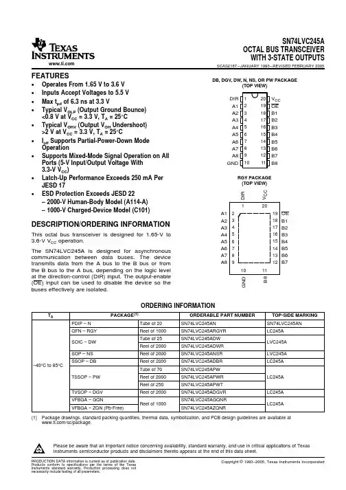
74LVC245A; 74LVCH245AOctal bus transceiver; 3-stateRev. 9 — 11 September 2018Product data sheet1. General descriptionThe 74LVC245A; 74LVCH245A are 8-bit transceivers featuring non-inverting 3-state buscompatible outputs in both send and receive directions. The device features an output enable(OE) input for easy cascading and a send/receive (DIR) input for direction control. OE controls theoutputs so that the buses are effectively isolated.Inputs can be driven from either 3.3 V or 5 V devices. When disabled, up to 5.5 V can be applied tothe outputs. These features allow the use of these devices in mixed 3.3 V and 5 V applications.The 74LVCH245A bus hold on data inputs eliminates the need for external pull-up resistors to holdunused inputs.2. Features and benefits• 5 V tolerant inputs/outputs for interfacing with 5 V logic•Wide supply voltage range from 1.2 V to 3.6 V•CMOS low-power consumption•Direct interface with TTL levels•Inputs accept voltages up to 5.5 V•High-impedance when V CC = 0 V•Bus hold on all data inputs (74LVCH245A only)•Complies with JEDEC standard:•JESD8-7A (1.65 V to 1.95 V)•JESD8-5A (2.3 V to 2.7 V)•JESD8-C/JESD36 (2.7 V to 3.6 V)•ESD protection:•HBM JESD22-A114F exceeds 2000 V•MM JESD22-A115B exceeds 200 V•CDM JESD22-C101E exceeds 1000 V•Specified from -40 °C to +85 °C and -40 °C to +125 °C3. Ordering information4. Functional diagram5. Pinning information5.1. Pinning74LVC245A 74LVCH245ADIR V CC A0OE A1B0A2B1A3B2A4B3A5B4A6B5A7B6GND B7001aak2921234567891012111413161518172019Fig. 3.Pin configuration SOT163-1 (SO20),SOT339-1 (SSOP20) and SOT360-1 (TSSOP20)001aak29374LVC245A 74LVCH245AT ransparent top viewB6A6A7B5A5B4A4B3A3B2A2B1A1B0A0OE G N D B 7D I R V C C9128137146155164173182191011120terminal 1 index areaGND (1)(1) This is not a supply pin. The substrate is attached to this pad using conductive die attach material. There is no electrical or mechanical requirement to solder this pad. However, if it is soldered, the solder land should remain floating or be connected to GND.Fig. 4.Pin configuration SOT764-1 (DHVQFN20)5.2. Pin description6. Functional descriptionTable 3. Function selectionH = HIGH voltage level; L = LOW voltage level; X = don’t care; Z = high impedance OFF-state.7. Limiting valuesTable 4. Limiting valuesIn accordance with the Absolute Maximum Rating System (IEC 60134). Voltages are referenced to GND (ground = 0 V).[1]The minimum input voltage ratings may be exceeded if the input current ratings are observed.[2]The output voltage ratings may be exceeded if the output current ratings are observed.[3]For SO20 packages: above 70 °C derate linearly with 8 mW/K.For (T)SSOP20 packages: above 60 °C derate linearly with 5.5 mW/K.For DHVQFN20 packages: above 60 °C derate linearly with 4.5 mW/K.8. Recommended operating conditions9. Static characteristicsTable 6. Static characteristicsAt recommended operating conditions. Voltages are referenced to GND (ground = 0 V).[1]All typical values are measured at V CC = 3.3 V (unless stated otherwise) and T amb = 25 °C.[2]The bus hold circuit is switched off when V I ˃ V CC allowing 5.5 V on the input terminal.[3]For I/O ports the parameter I OZ includes the input leakage current.[4]Valid for data inputs of bus hold parts only (74LVCH245A). Note that control inputs do not have a bus hold circuit.[5]The specified sustaining current at the data input holds the input below the specified V I level.[6]The specified overdrive current at the data input forces the data input to the opposite input state.10. Dynamic characteristicsTable 7. Dynamic characteristicsVoltages are referenced to GND (ground = 0 V). For test circuit see Fig. 7.[1]Typical values are measured at T amb = 25 °C and V CC = 1.2 V, 1.8 V, 2.5 V, 2.7 V and 3.3 V respectively.[2]t pd is the same as t PLH and t PHL.t en is the same as t PZL and t PZH.t dis is the same as t PLZ and t PHZ.[3]Skew between any two outputs of the same package switching in the same direction. This parameter is guaranteed by design.[4]C PD is used to determine the dynamic power dissipation (P D in μW).P D = C PD × V CC2 × f i × N + Σ(C L × V CC2 × f o) where:f i = input frequency in MHz; f o = output frequency in MHzC L = output load capacitance in pFV CC = supply voltage in VoltsN = number of inputs switchingΣ(C L × V CC2 × f o) = sum of the outputs.10.1. Waveforms and test circuit11. Package outlineSO20: plastic small outline package; 20 leads; body width 7.5 mm SOT163-1Fig. 8.Package outline SOT163-1 (SO20)SSOP20: plastic shrink small outline package; 20 leads; body width 5.3 mm SOT339-1Fig. 9.Package outline SOT339-1 (SSOP20)TSSOP20: plastic thin shrink small outline package; 20 leads; body width 4.4 mm SOT360-1Fig. 10.Package outline SOT360-1 (TSSOP20)DHVQFN20: plastic dual in-line compatible thermal enhanced very thin quad flat package; no leads;Fig. 11.Package outline SOT764-1 (DHVQFN20)12. Abbreviations13. Revision history14. Legal informationData sheet status[1]Please consult the most recently issued document before initiating orcompleting a design.[2]The term 'short data sheet' is explained in section "Definitions".[3]The product status of device(s) described in this document may havechanged since this document was published and may differ in case ofmultiple devices. The latest product status information is available onthe internet at https://.DefinitionsDraft — The document is a draft version only. The content is still under internal review and subject to formal approval, which may result in modifications or additions. Nexperia does not give any representations or warranties as to the accuracy or completeness of information included herein and shall have no liability for the consequences of use of such information. Short data sheet — A short data sheet is an extract from a full data sheet with the same product type number(s) and title. A short data sheet is intended for quick reference only and should not be relied upon to contain detailed and full information. For detailed and full information see the relevant full data sheet, which is available on request via the local Nexperia sales office. In case of any inconsistency or conflict with the short data sheet, the full data sheet shall prevail.Product specification — The information and data provided in a Product data sheet shall define the specification of the product as agreed between Nexperia and its customer, unless Nexperia and customer have explicitly agreed otherwise in writing. In no event however, shall an agreement be valid in which the Nexperia product is deemed to offer functions and qualities beyond those described in the Product data sheet.DisclaimersLimited warranty and liability — Information in this document is believedto be accurate and reliable. However, Nexperia does not give any representations or warranties, expressed or implied, as to the accuracyor completeness of such information and shall have no liability for the consequences of use of such information. Nexperia takes no responsibility for the content in this document if provided by an information source outside of Nexperia.In no event shall Nexperia be liable for any indirect, incidental, punitive, special or consequential damages (including - without limitation - lost profits, lost savings, business interruption, costs related to the removalor replacement of any products or rework charges) whether or not such damages are based on tort (including negligence), warranty, breach of contract or any other legal theory.Notwithstanding any damages that customer might incur for any reason whatsoever, Nexperia’s aggregate and cumulative liability towards customer for the products described herein shall be limited in accordance with the Terms and conditions of commercial sale of Nexperia.Right to make changes — Nexperia reserves the right to make changesto information published in this document, including without limitation specifications and product descriptions, at any time and without notice. This document supersedes and replaces all information supplied prior to the publication hereof.Suitability for use — Nexperia products are not designed, authorized or warranted to be suitable for use in life support, life-critical or safety-critical systems or equipment, nor in applications where failure or malfunctionof an Nexperia product can reasonably be expected to result in personal injury, death or severe property or environmental damage. Nexperia and its suppliers accept no liability for inclusion and/or use of Nexperia products in such equipment or applications and therefore such inclusion and/or use is at the customer’s own risk.Quick reference data — The Quick reference data is an extract of the product data given in the Limiting values and Characteristics sections of this document, and as such is not complete, exhaustive or legally binding. Applications — Applications that are described herein for any of these products are for illustrative purposes only. Nexperia makes no representation or warranty that such applications will be suitable for the specified use without further testing or modification.Customers are responsible for the design and operation of their applications and products using Nexperia products, and Nexperia accepts no liability for any assistance with applications or customer product design. It is customer’s sole responsibility to determine whether the Nexperia product is suitableand fit for the customer’s applications and products planned, as well asfor the planned application and use of customer’s third party customer(s). Customers should provide appropriate design and operating safeguards to minimize the risks associated with their applications and products. Nexperia does not accept any liability related to any default, damage, costs or problem which is based on any weakness or default in the customer’s applications or products, or the application or use by customer’s third party customer(s). Customer is responsible for doing all necessary testing for the customer’s applications and products using Nexperia products in order to avoid a default of the applications and the products or of the application or use by customer’s third party customer(s). Nexperia does not accept any liability in this respect.Limiting values — Stress above one or more limiting values (as defined in the Absolute Maximum Ratings System of IEC 60134) will cause permanent damage to the device. Limiting values are stress ratings only and (proper) operation of the device at these or any other conditions above thosegiven in the Recommended operating conditions section (if present) or the Characteristics sections of this document is not warranted. Constant or repeated exposure to limiting values will permanently and irreversibly affect the quality and reliability of the device.Terms and conditions of commercial sale — Nexperia products aresold subject to the general terms and conditions of commercial sale, as published at /profile/terms, unless otherwise agreed in a valid written individual agreement. In case an individual agreement is concluded only the terms and conditions of the respective agreement shall apply. Nexperia hereby expressly objects to applying the customer’s general terms and conditions with regard to the purchase of Nexperia products by customer.No offer to sell or license — Nothing in this document may be interpreted or construed as an offer to sell products that is open for acceptance or the grant, conveyance or implication of any license under any copyrights, patents or other industrial or intellectual property rights.Export control — This document as well as the item(s) described herein may be subject to export control regulations. Export might require a prior authorization from competent authorities.Non-automotive qualified products — Unless this data sheet expressly states that this specific Nexperia product is automotive qualified, the product is not suitable for automotive use. It is neither qualified nor tested in accordance with automotive testing or application requirements. Nexperia accepts no liability for inclusion and/or use of non-automotive qualified products in automotive equipment or applications.In the event that customer uses the product for design-in and use in automotive applications to automotive specifications and standards, customer (a) shall use the product without Nexperia’s warranty of the product for such automotive applications, use and specifications, and (b) whenever customer uses the product for automotive applications beyond Nexperia’s specifications such use shall be solely at customer’s own risk, and (c) customer fully indemnifies Nexperia for any liability, damages or failed product claims resulting from customer design and use of the product for automotive applications beyond Nexperia’s standard warranty and Nexperia’s product specifications.Translations — A non-English (translated) version of a document is for reference only. The English version shall prevail in case of any discrepancy between the translated and English versions.TrademarksNotice: All referenced brands, product names, service names and trademarks are the property of their respective owners.Contents1. General description (1)2. Features and benefits (1)3. Ordering information (2)4. Functional diagram (2)5. Pinning information (3)5.1. Pinning (3)5.2. Pin description (3)6. Functional description (3)7. Limiting values (4)8. Recommended operating conditions (4)9. Static characteristics (5)10. Dynamic characteristics (7)10.1. Waveforms and test circuit (8)11. Package outline (10)12. Abbreviations (14)13. Revision history (14)14. Legal information (15)© Nexperia B.V. 2018. All rights reservedFor more information, please visit: Forsalesofficeaddresses,pleasesendanemailto:*************************** Date of release: 11 September 2018。