AD7813资料
- 格式:pdf
- 大小:186.58 KB
- 文档页数:11
REV. B
Information furnished by Analog Devices is believed to be accurate and
reliable. However, no responsibility is assumed by Analog Devices for its
use, nor for any infringements of patents or other rights of third parties
which may result from its use. No license is granted by implication or
otherwise under any patent or patent rights of Analog Devices.a
AD7813
One Technology Way, P.O. Box 9106, Norwood, MA 02062-9106, U.S.A.
Tel: 781/329-4700World Wide Web Site: http://www.analog.com
Fax: 781/326-8703© Analog Devices, Inc., 2000+2.7 V to +5.5 V, 400 kSPS
8-/10-Bit Sampling ADC
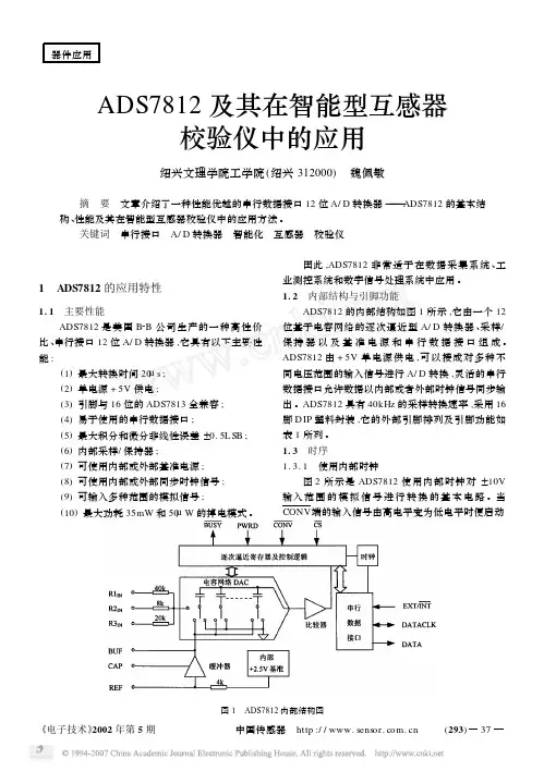
FUNCTIONAL BLOCK DIAGRAM
V
IN
COMP
CONVSTV
DDAGNDV
REF
CHARGE
REDISTRIBUTION
DACDB7
THREE-
STATE
DRIVERS
CLOCK
OSC
BUSYCSRDDB0
CONTROL
LOGICT/HAD7813FEATURES
8-/10-Bit ADC with 2.3 s Conversion Time
On-Chip Track and Hold
Operating Supply Range: +2.7 V to +5.5 V
Specifications at 2.7 V–3.6 V and 5 V ؎ 10%
8-Bit Parallel Interface
8-Bit + 2-Bit Read
Power Performance
Normal Operation
10.5 mW, V
DD = 3 V
Automatic Power-Down
34.6 W @ 1 kSPS, V
DD = 3 V
Analog Input Range: 0 V to V
REF
Reference Input Range: 1.2 V to V
DD
GENERAL DESCRIPTION
The AD7813 is a high-speed, microprocessor-compatible,
8-/10-bit analog-to-digital converter with a maximum through-
put of 400 kSPS. The converter operates off a single +2.7 V to
+5.5 V supply and contains a 2.3 µs successive approximation
A/D converter, track/hold circuitry, on-chip clock oscillator and
8-bit wide parallel interface. The parallel interface is designed to
allow easy interfacing to microprocessors and DSPs. The 10-bit
conversion result is read by carrying out two 8-bit read opera-
tions. The first read operation accesses the 8 MSBs of the ADC
conversion result and the second read accesses the 2 LSBs.
Using only address decoding logic the AD7813 is easily mapped
into the microprocessor address space.
When used in its power-down mode, the AD7813 automatically
powers down at the end of a conversion and powers up at the
start of a new conversion. This feature significantly reduces the
power consumption of the part at lower throughput rates. The
AD7813 can also operate in a high speed mode where the part is
not powered down between conversions. In this mode of opera-
tion the part is capable of providing 400 kSPS throughput.
The part is available in a small, 16-lead, 0.3" wide, plastic dual-
in-line package (DIP), in a 16-lead, 0.15" wide, narrow body
small outline IC (SOIC) and in a 16-lead thin shrink small
outline package (TSSOP).PRODUCT HIGHLIGHTS
1.Low Power, Single Supply Operation
The AD7813 operates from a single +2.7 V to +5.5 V sup-
ply and typically consumes only 10.5 mW of power. The
power dissipation can be significantly reduced at lower
throughput rates by using the automatic power-down mode.
2.Automatic Power-Down
The automatic power-down mode, whereby the AD7813
goes into power-down mode at the end of a conversion and
powers up before the next conversion, means the AD7813
is ideal for battery powered applications; e.g., 34.6 µW
@ 1 kSPS. (See Power vs. Throughput Rate section.)
3.Parallel Interface
An easy to use 8-bit-wide parallel interface allows interfacing
to most popular microprocessors and DSPs with minimal
external circuitry.
4.Dynamic Specifications for DSP Users
In addition to the traditional ADC specifications, the AD7813
is specified for ac parameters, including signal-to-noise ratio
and distortion.元器件交易网www.cecb2b.comREV. BAD7813–SPECIFICATIONS1(GND = 0 V, V
REF = +V
DD = 3 V ؎ 10% to 5 V ؎ 10%. All specifications –40؇C to
+105؇C unless otherwise noted.)
ParameterY VersionUnitTest Conditions/Comments
DYNAMIC PERFORMANCEf
IN = 30 kHz, f
SAMPLE = 350 kHz
Signal to (Noise + Distortion) Ratio158dB min
Total Harmonic Distortion (THD)1–66dB max
Peak Harmonic or Spurious Noise1–66dB max
Intermodulation Distortion2fa = 29.1 kHz, fb = 29.8 kHz
2nd Order Terms–67dB typ
3rd Order Terms–67dB typ
DC ACCURACY
Resolution10Bits
Minimum Resolution for Which
No Missing Codes Are Guaranteed10Bits
Relative Accuracy1±1LSB max
Differential Nonlinearity (DNL)1±1LSB max
Gain Error1±2LSB max
Offset Error1±2.0LSB max
ANALOG INPUT
Input Voltage Range0V min
V
REFV max
Input Leakage Current2±1µA max
Input Capacitance220pF max
REFERENCE INPUTS2
V
REF Input Voltage Range1.2V min
V
DDV max
Input Leakage Current±3µA max
Input Capacitance15pF max
LOGIC INPUTS2
V
INH, Input High Voltage2.0V min
V
INL, Input Low Voltage0.4V max(0.8 V max, V
DD = 5 V)
Input Current, I
IN±1µA maxTypically 10 nA, V
IN = 0 V to V
DD
Input Capacitance, C
IN8pF max
LOGIC OUTPUTS
Output High Voltage, V
OH2.4V minI
SOURCE = 200 µA
Output Low Voltage, V
OL0.4V maxI
SINK = 200 µA
High Impedance Leakage Current±1µA max
High Impedance Capacitance15pF max
CONVERSION RATE