SATA硬盘电源接口
- 格式:doc
- 大小:89.50 KB
- 文档页数:3

SATA电源线和数据线定义
DATA为数据端
从平端到突起端分别为pin1-7
1 GND 接地
2 A+ 数据发送正极信号
3 A- 数据发送负极信号
4 GND 接地
5 B- 数据接收负极信号
6 B+ 数据接收正极信号
7 GND 接地
POWER为供电端
从突起端到平端分别为pin1-15
1 V33 3.3V直流电源正极
2 V3
3 3.3V直流电源正极
3 V33 3.3V直流电源正极,预充电,与第二路配对
4 GNDM1 接地,与第一路匹配
5 GNDM2 接地,与第二路匹配
6 GNDM3 接地,与第三路匹配
7 V5 5V直流电源正极,预充电,与第二路配对
8 V5 5V直流电源正极
9 V5 5V直流电源正极
10 GND 接地,与第二路配对
11 Reserved 预留
12 GNDM1 接地,与第一路匹配
13 V12 12V直流电源正极,预充电,与第二路配对
14 V12 12V直流电源正极
15 V12 12V直流电源正极
电源线定义
黄色直流12V
黑色GND
红色直流5V
黑色GND
橙色直流3.3V
3.3V不接可正常使用,但有硬盘会出现不识别情况
2.5英寸硬盘+12V脚悬空。
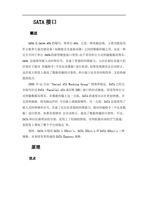
SATA接口概述SATA是Serial ATA的缩写,即串行ATA。
它是一种电脑总线,主要功能是用作主板和大量存储设备(如硬盘及光盘驱动器)之间的数据传输之用。
这是一种完全不同于串行PATA的新型硬盘接口类型,由于采用串行方式传输数据而得名。
SATA总线使用嵌入式时钟信号,具备了更强的纠错能力,与以往相比其最大的区别在于能对传输指令(不仅仅是数据)进行检查,如果发现错误会自动矫正,这在很大程度上提高了数据传输的可靠性。
串行接口还具有结构简单、支持热插拔的优点。
2000 年11月由“Serial ATA Working Group”团体所制定,SATA已经完全取代旧式PATA(Parallel ATA或旧称IDE)接口的旧式硬盘,因采用串行方式传输数据而得名。
在数据传输上这一方面,SATA的速度比以往更加快捷,并支持热插拔,使电脑运作时可以插上或拔除硬件。
另一方面,SATA总线使用了嵌入式时钟频率信号,具备了比以往更强的纠错能力,能对传输指令(不仅是数据)进行检查,如果发现错误会自动矫正,提高了数据传输的可靠性。
不过,SATA和以往最明显的分别,是用上了较细的排线,有利机箱内部的空气流通,某程度上增加了整个平台的稳定性。
现时,SATA分别有SATA 1.5Gbit/s、SATA 3Gbit/s和SATA 6Gbit/s三种规格。
未来将有更快速的SATA Express规格。
原理优点与并行ATA相比,SATA具有比较大的优势。
首先,Serial ATA以连续串行的方式传送数据,可以在较少的位宽下使用较高的工作频率来提高数据传输的带宽。
Serial ATA一次只会传送1位数据,这样能减少SATA接口的针脚数目,使连接电缆数目变少,效率也会更高。
实际上,Serial ATA 仅用四支针脚就能完成所有的工作,分别用于连接电缆、连接地线、发送数据和接收数据,同时这样的架构还能降低系统能耗和减小系统复杂性。
其次,Serial ATA的起点更高、发展潜力更大,Serial ATA 1.0定义的数据传输率可达150MB/sec,这比目前最快的并行ATA(即ATA/133)所能达到133MB/sec的最高数据传输率还高,而在已经发布的Serial ATA 2.0的数据传输率将达到300MB/sec,最终Serial ATA 3.0将实现600MB/sec的最高数据传输率。
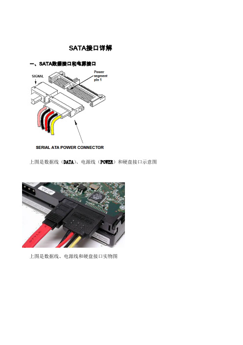
SATA接口详解一、SATA数据接口和电源接口上图是数据线(DATA)、电源线(POWER)和硬盘接口示意图上图是数据线、电源线和硬盘接口实物图上图是 SATA数据线(7针)对应硬盘上的数据接口(7针)特写上图是 SATAS数据线(母口)特写,(硬盘上接口成为公口)二、数据接口(7针)定义引脚定义:1 GND Ground 接地,一般和负极相连2 A Transmit 数据发送正极信号接口3 A- Transmit 数据发送负极信号接口4 GND Ground 接地,一般和负极相连5 B- Receive 数据接收负极信号接口6 B Receive 数据接收正极信号接口7 GND Ground 接地,一般和负极相连三、电源接口(15针)定义针脚信号线颜色定义1 +3.3VDC 直流 3.3V 正极电源针脚2 +3.3VDC 直流 3.3V 正极电源针脚3 +3.3VDC 直流 3.3V 正极电源针脚,预充电,与第二路配对4 GND 接地,一般和负极相连,与第 1 路配对5 GND 接地,一般和负极相连,与第 2 路配对6 GND 接地,一般和负极相连,与第 3 路配对7 +5VDC 直流5V 正极电源针脚,预充电,与第二路配对8 +5VDC 直流5V 正极电源针脚9 +5VDC 直流5V 正极电源针脚10 GND 接地,一般和负极相连,与第 2 路配对11 Optional 保留的针脚12 GND 接地,一般和负极相连,与第 1 路配对13 +12VDC 黄色直流12V 正极电源针脚,预充电,与第二路配对14 +12VDC 黄色直流12V 正极电源针脚15 +12VDC 黄色直流12V 正极电源针脚。

SATA是Serial ATA的缩写,即串行ATA。
2001年,由Intel、APT、Dell、IBM、希捷、迈拓这几大厂商组成的Serial ATA委员会正式确立了Serial ATA 1.0规范,2002年确立了Serial ATA 2.0规范。
Serial ATA 采用串行连接方式,串行ATA总线使用嵌入式时钟信号,具备了更强的纠错能力,还具有结构简单、支持热插拔的优点。
目前已经成了桌面硬盘的主力接口。
一、SATA数据和电源接口图:二、电源内部联接图:三、电源和数据线接口定义图:四、SATA接口定义描述:1、SATA数据接口定义:1 GND Ground(接地,一般和负极相连)2 A Transmit(数据发送正极信号接口)3 A- Transmit(数据发送负极信号接口4 GND Ground(接地,一般和负极相连)5 B- Receive (数据接收负极信号接口) -6 B Receive (数据接收正极信号接口)7 GND Ground(接地,一般和负极相连)2、电源接口定义:01 V33 3.3v Power (直流3.3V正极电源针脚)02 V33 3.3v Power (直流3.3V正极电源针脚)03 V33 3.3v Power, Pre-charge, 2nd mate (直流3.3V正极电源针脚,预充电,与第二路配对)04 Ground 1st Mate (接地,一般和负极相连,与第1路配对)05 Ground 2nd Mate (接地,一般和负极相连,与第2路配对)06 Ground 3rd Mate (接地,一般和负极相连,与第3路配对)07 V5 5v Power, pre-charge, 2nd mate (直流5V正极电源针脚,预充电,与第二路配对)08 V5 5v Power (直流5V正极电源针脚)09 V5 5v Power (直流5V正极电源针脚)10 Ground 2nd Mate (接地,一般和负极相连,与第2路配对)11 Reserved –保留的针脚12 Ground 1st Mate (接地,一般和负极相连,与第1路配对)13 V12 12v Power, Pre-charge, 2nd mate (直流12V正极电源针脚,预充电,与第二路配对)14 V12 12v Power (直流12V正极电源针脚)15 V12 12v Power (直流12V正极电源针脚)3、SATA电源线颜色释义(1)、黄色-直流12V正极(2)、黑色-直流12V负极(GND)(3)、红色-直流5V正极(GND,VSS)(4)、黑色5V负极(GND)(5)、橙色-直流3.3V正极PS:(1) 3.3V不接是一样的正常使用,但有用不带3.3V的电源线接的SATA硬盘不认的情况。

SATA笔记本光驱电源线接线图
笔记本光驱电源接⼝是6pin的,如图:
如图所⽰,笔记本光驱的接⼝分为两部分,左为数据,右为供电,供电针脚从左起为1,⼀共6个针脚,分别是
1)设备检测
2) +5V供电
3) +5V供电
4)⼚商测试
5)地线
6)地线
笔记本和台式机硬盘的标准接⼝,同样是两部分,左为数据,右为供电,左起为1。
这15个针脚分别是
1) +3.3V
2) +3.3V
3) +3.3V
4)地线
5)地线
6)地线
7) +5V
8) +5V
9) +5V
10)地线
11)旋转/停转控制
12)地线
13) +12V
14) +12V
15) +12V
需要注意的是,由于不常使⽤,许多情况下+3.3V(橙⾊线)都被省略了,笔记本上的供电接⼝不提供+12V(台式机黄⾊线)的。
到⽬前为⽌,3.5⼨硬盘都是需要+12V供电才可以正常⼯作的,只通过+5V供电,所以笔记本暂时还⽤不了3.5⼨硬盘。
每个计算机系统,不论台式PC还是笔记本电脑,都会有很多接口。
你能正确识别每一个接口么?尽管他们触手可及,却总是出现各种各样的状况。
这篇文章包罗万象,为新用户和经历问题的使用者提供帮助。
通过大量图片和注释,将告诉你电脑各种接口、插槽、插头的作用。
值得安慰的是,大多数接口都不太容易弄错,主要依靠“防呆”设计;如果有特殊情况,文章中会特别注明。
(防呆设计:通过一些突出或凹陷的部分,使接口不能或不容易被插反插错,从而保护接口与硬件)我们将接口整体分为两部分:外部接口:电脑的外设联接接口内部接口:计算机系统里的接口外部接口:电脑的外设联接接口插头插座名称USBIEEE 1394/ Firewire / i.Link / 火线Cinch / RCAPS/2 键盘鼠标接口VGA显示器视频接口DVI数字视频接口RJ45 (LAN /ISDN)网线接口RJ11(Modem / 电话)S-Video (Hosiden)内部接口:计算机系统里的接口插头插座名称SATA (Serial ATA)PATA (Parallel ATA / UltraDMA/133 / IDE)agp(Graphics Cards) PCIe (pci Express) PCIPOWER 电源接口外部接口:USBUniversal Serial Bus (USB)万用串行总线,被设计为联接各种外部设备。
譬如鼠标、键盘、移动硬盘、数码相机、VoIP电话(Skype)或打印机。
理论上一个USB控制器,可以联接127个USB设备(当然,理想与现实总是有些差距^_^)。
USB 1.1峰值传输速率为12Mbps,USB 2.0峰值为480Mbps。
USB 2.0可以向下兼容,当USB 2.0设备插入1.1接口,将只有12Mbps的传输速率。
USB可以通过线缆传送电力,能够为移动硬盘提供电能(最大500mA、5V)。
USB接口分为三种:接口类型A:通常在PC上出现接口类型B:通常在USB设备上出现Mini-USB:数码相机和摄像机、移动硬盘等设备经常使用。
SATA硬盘如何热插拔2009-10-09 10:24SATA硬盘没有设置主从盘,一条SATA线只接一个盘插在主板SATA接口1上,就是主,在2上是从最近换了一块1TB硬盘,欣喜之下却发现一个问题,笔者原来有4块SATA硬盘,但是现在数据转移就成了问题,机箱里只有两个SATA电源接口,如果来回开关机插拔硬盘又十分麻烦,情急之下,笔者想出一个高招——热插拔!其实SATA接口的初衷就是实现热插拔,不过这一特点只有eSATA发挥得不错,那SATA硬盘到底是否支持热插拔呢?答案肯定,不过方法有些特殊。
下面就一起来跟我操作吧!首先打开机箱,找到SATA的电源线(没有的话用4Pin的SATA转接头也行),快速插入硬盘电源插口,不要犹豫,听到硬盘转动声音后,再插上数据线。
也许你会发现系统并没有识别出来,很简单,右击计算机——属性——设备管理器(我的电脑——属性——硬件——设备管理器),打开设备管理器,然后点击工具栏上的“扫描新硬件”按钮,系统就会自动扫描并识别你的SATA硬盘了。
赶快转移你的数据吧!热插虽然简单,但是热拔呢?同样简单,只要把操作步骤反过来就行了。
先打开设备管理器,展开“磁盘驱动器”分支,右击你想拔下的硬盘,选择卸载,等系统提示驱动器卸载完成的时候,就可以拔下硬盘了。
首先拔下数据线,然后再拔下电源线(不要犹豫),这样硬盘就实现了热插拔。
注意,插拔数据线和电源线的顺序千万不要弄反,否则系统会死机的……到时候你的数据……拔下硬盘的时候一定要先卸载硬盘,否则数据丢失的时候可不要来找我哦~~要求:只有符合希捷定的S-ATA V2.5规范才可以完美支持热插拔,否则即使能够热插拔也会对硬件有损害。
另外也不是所有的主板都支持V2.5规范,当然啦,大多数主板是支持的。
目前主流硬盘已经基本全面转向Ver2.5规范,其中最放心最好辨认的就是希捷酷鱼7200.9和7200.10这两个系列,全系列型号都是V2.5规范产品,均可良好支持热插拔.SATA是否支持热拨插由主板与硬盘来决定。
硬盘电源线接法图解主板上有专门的硬盘接口,用硬盘或者主板带的数据线连接,注意有方向性。
机箱电源上有很多电源线插头,选择合适的接口插入硬盘后面的对应规格接口,也有方向的。
机箱电源线大多数接口相似,是联硬盘光驱的,独特的大口,接主板上供电。
如不会,可找个DIY 组装电脑的书看,版本要新些的。
或者找视频看。
实在不行就找会的可靠的人帮忙。
注意一定要先拔下电脑主机和交流电市电连接的电源线。
光关闭电脑主机开关不行。
左边是并口硬盘的接法,右边是串口硬盘的接法新的SATA串口的硬盘和光驱采用了新式的电源接口,找找电源出来的线应该有比较宽的,一般为黑色的很扁的插头,把那个插头接到光驱和硬盘相对应的口上就行了。
一、初识SATA硬盘SATA硬盘与PATA硬盘从外观上粗看是差不多的,它们最主要的区别在连接线上。
两块不同接口的硬盘放在了一起(如图1),图1首先让我们来看一看它们的信号线,以往的PATA硬盘采用的是40或80针的扁平硬盘线作为传输数据的通道,而SATA接口的硬盘采用的是七芯的数据线,采用点对点的传输协议,仅使用两根数据线进行信号传送,这样就不会受到机箱内各种频率的干扰,使硬盘缓存中的数据可以顺畅无阻的传送至内存中进行处理,而它的传输速度在设计时就比PATA硬盘快,所以SATA接口的硬盘在速度上要比普通PATA 硬盘有所提高。
SATA信号线除抗干扰外,它还比PATA数据线轻薄很多。
SATA信号线的宽度仅为1厘米多一点,而长度却可达1米,而传统的PATA硬盘信号线则宽达4.5厘米,长度又不能超过40厘米(如图2)。
图2在电源线上SATA与PATA硬盘也各不相同。
这是因为SATA硬盘需要3.3V、5V和12V等多种电压,几种不同电压加起来就需要输入电源线要有15个针脚了。
而我们以前使用的PATA硬盘采用是D型4针电源接口,而由于在一些旧电源上并没有为SATA硬盘提供专门的电源线插头,所以很多SATA硬盘除了SATA硬盘的专用电源接口之外,还提供了传统PATA硬盘使用的D型4针电源接口(如图3)。
SA TA接口定义SA TA是Serial A TA的缩写,即串行A TA。
2001年,由Intel、APT、Dell、IBM、希捷、迈拓这几大厂商组成的Serial A TA委员会正式确立了Serial A TA 1.0规范,2002年确立了Serial A TA 2.0规范。
Serial A TA采用串行连接方式,串行A TA总线使用嵌入式时钟信号,具备了更强的纠错能力,还具有结构简单、支持热插拔的优点。
目前已经成了桌面硬盘的主力接口。
一、SATA数据和电源接口图:二、电源内部联接图:三、电源和数据线接口定义图:(借用了别人的,引用地址:/33640537_674534_d.html)四、SATA接口定义描述:1、SATA数据接口定义:1 GND Ground(接地,一般和负极相连)2 A Transmit(数据发送正极信号接口)3 A- Transmit(数据发送负极信号接口4 GND Ground(接地,一般和负极相连)5 B- Receive (数据接收负极信号接口)-6 B Receive (数据接收正极信号接口)7 GND Ground(接地,一般和负极相连)2、电源接口定义:01 V33 3.3v Power (直流3.3V正极电源针脚)02 V33 3.3v Power (直流3.3V正极电源针脚)03 V33 3.3v Power, Pre-charge, 2nd mate (直流3.3V正极电源针脚,预充电,与第二路配对)04 Ground 1st Mate (接地,一般和负极相连,与第1路配对)05 Ground 2nd Mate (接地,一般和负极相连,与第2路配对)06 Ground 3rd Mate (接地,一般和负极相连,与第3路配对)07 V5 5v Power, pre-charge, 2nd mate (直流5V正极电源针脚,预充电,与第二路配对)08 V5 5v Power (直流5V正极电源针脚)09 V5 5v Power (直流5V正极电源针脚)10 Ground 2nd Mate (接地,一般和负极相连,与第2路配对)11 Reserved –保留的针脚12 Ground 1st Mate (接地,一般和负极相连,与第1路配对)13 V12 12v Power, Pre-charge, 2nd mate (直流12V正极电源针脚,预充电,与第二路配对)14 V12 12v Power (直流12V正极电源针脚)15 V12 12v Power (直流12V正极电源针脚)3、SA TA电源线颜色释义(1)、黄色-直流12V正极(2)、黑色-直流12V负极(GND)(3)、红色-直流5V正极(GND,VSS)(4)、黑色5V负极(GND)(5)、橙色-直流3.3V正极串行高技术附件(SATA)接口技术是连接主机和存储系统的新兴接口技术,其采用串行方式进行数据传输。
SATA15针电源接口定义/sata信号线定义2010年04月07日星期三14:46这些天在写esata的驱动,所以将相关资料贴上!•In computer hardware, Serial ATA(SATA, is a computer bus technology primarily designed for transfer of data to and from a hard disk. It is the successor to the legacy Advanced Technology Attachment standard (ATA, also known as IDE). This older technology was retroactively renamed Parallel ATA (PA TA) to distinguish it from Serial ATA.The Serial ATA [SATA] bus is defined over two separate connectors, one connector for the data lines and one for the power lines. A Serial ATA Hard drive may also have a third connector for legacy PATA power connections. The PATA power connector may be used in instead of the SATA power to supply a connection which is more rugged and reliable then the SATA-1 power connection.The Serial ATA interface [SATA] is the serial version of the IDE [ATA] spec. SATA uses a 4 conductor cable with two differential pairs [Tx/Rx], plus an additional 3 grounds pins and a separate power connector. Data runs at 150MBps [1.5GHz] using 8B/10B encoding and 250mV signal swings, with a maximum bus length of 1 meter. SATA enhancements move the data transfer speed to; 300MBps [3.0Gbps], and then 600MBps [6.0Gbps]. The current speed for SATA is 300Mbps [3Gbps]. Shielded external SATA [eSATA] data cable runs out to a maximum of between 3 feet and 6 feet. eSATA cables are used external to the chassis or case.SATA Data pinout SATA PinOut, Data Pin #Signal Name Signal Description1 GND Ground 2A+ Transmit + 3A- Transmit - 4GND Ground 5B- Receive - 6B+ Receive + 7GND Ground SATA Power pinout SATA PinOut, Power Pin #Signal Name Signal Description1 V33 3.3v Power 2 V33 3.3v Power 3 V33 3.3v Power, Pre-charge, 2nd mate 4 Ground 1st Mate5 Ground 2nd Mate6 Ground 3rd Mate7 V5 5v Power, pre-charge, 2nd mate8 V5 5v Power 9V5 5v Power 10 Ground 2nd Mate 11 Reserved - 12 Ground 1st Mate 13 V12 12v Power, Pre-charge, 2nd mate 14 V12 12v Power 15 V12 12v Power PATA Power pinout IDE Power Connector Pin Out Pin #Signal Function18 A WG Wire 1 +12V DC Yellow 2 +12V Return Black 3 +5V Return Black 4 +5V DC Red SATA signal names are with respect to the Host, the device connected to the host reverses the signal names. Transmit pins connect to Receive pins on the other device. The SATA connector is keyed at pin 1. These pin outs for the Serial ATA connector are not compatible with the legacy PATA connector.[The following article is licensed under the GNU Free Documentation License. It reproduces the Wikipedia article "Serial ATA"]SATA 1.5 Gb/sFirst-generation Serial ATA interfaces, also known as SATA/150, run at 1.5 Gigahertz (GHz). Serial A TA uses 8B/10B encoding at the physical layer. This encoding scheme has an efficiency of 80%, resulting in an actual data transfer rate of 1.2 Gigabits per second (Gb/s), or 150 megabytes per second (MB/s). The relative simplicity of a serial link and the use of LVDS allow both the use of longer drive cables and an easier transition path to higher speeds.SATA 3.0 Gb/sSoon after SATA's introduction, enhancements were made to the standard. A 3Gb/s signalling rate was added to the PHY layer, offering up to twice the data throughput. To ensure seamless backward compatibility between older SATA and the newer faster SATA/3Gbs devices, the latter devices are required to support the original 1.5Gb/s rate. In practice, some older SATA systems that do not support SATA speed negotiation require the peripheral drive's speed be manually hardlimited to 150Â MB/s with the use of a jumper for a 300Â MB/s drive.Like SATA 1.5Gb/s, SATA 3Gb/s uses 8B/10B encoding resulting in an actual data transfer rate of 2.4 Gb/s, or 300 MB/s.The 3.0Â Gb/s specification has been very widely referred to as “Serial ATA II” (“SATA II”), contrary to the wishes of the Serial ATA standards organization that authored it. The official website notes that SATA II was in fact that organization's name at the time, the SATA 3Gb/s specification being only one of many that the former SATA II defined, and suggests that “SA TA 3Gb/s” be used instead. (The Serial A TA standards organization has since changed names, and is now “The Serial ATA International Organization”, abbreviated SA TA-IO.) SATA-IO plans to further increase the maximum throughput of Serial ATA to 600Â MB/s around the year 2007.SATA 3Gb/s is sometimes also referred to as SATA/300 or SATA II, continuing the line of PATA/100, PATA/133 and SATA/150.SATA 6.0 Gb/sSATA-IO plans to make a 6.0 Gb/s standard. Although the theoretical thoroughput would be doubled, conventional hard disks can't approach saturating this speed. Serial ATA innovationsSATA drops the master/slave shared bus of PATA, giving each device a dedicated cable and dedicated bandwidth. While this requires twice the number of host controllers to support the same number of SATA devices, at the time of SATA's introduction this was no longer a significant drawback. Another controller could be added into a controller ASIC at little cost beyond the addition of the extra seven signal lines and printed circuit board (PCB) space for the cable header.Features allowed for by SATA but not by PA TA include hot-swapping and native command queueing.To ease their transition to SATA, many manufacturers have produced drives which use controllers largely identical to those on their PATA drives and include a bridge chip on the logic board. Bridged drives have a SATA connector, may include either or both kinds of power connectors, and generally perform identically to native drives. They may, however, lack support for some SATA-specific features. As of 2004, all major hard drive manufacturers produce either bridged or native SA TA drives.SATA drives may be plugged into Serial Attached SCSI (SAS) controllers and communicate on the same physical cable as native SAS disks. SAS disks, however, may not be plugged into aSATA controller.Cables and ConnectorsPhysically, the SATA power and data cables are the most noticeable change from Parallel A TA. The SATA standard defines a data cable using seven conductors and 8Â mm wide wafer connectors on each end. SATA cables can be up to 1 m (39 in) long.PATA ribbon cables, in comparison, carry either 40- or 80-conductor wires and are limited to 46 cm (18 in) in length. The reduction in conductors makes SATA connectors and cables much narrower than those of PATA, thus making them more convenient to route within tight spaces and reducing obstructions to air cooling. Unlike early PATA connectors, SATA connectors are keyed — it is not possible to install cable connectors upside down without considerable force.The SATA standard also specifies a power connector sharply differing from the four-pin Molex connector used by PATA drives and many other computer components. Like the data cable, it is wafer-based, but its wider 15-pin shape should prevent confusion between the two. The seemingly large number of pins are used to supply three different voltages if necessary —3.3Â V, 5Â V, and 12Â V. Each voltage is supplied by three pins gangedtogether (and 5 pins for ground). This is because the small pins cannot supply sufficient current for some devices, so they are combined. One pin from each of the three voltages is also used for hotplugging. The same physical connections are used on 3.5-in (90mm) and 2.5-in (70mm) (notebook) hard disks. Some SATA drives include in PA TA style four-pin Molex connector for use with power supplies that lack the SATA power connector. Also, adaptors are available to convert a PATA style power connector to SATA power connector.External SATAeSATA was standardized in mid-2004, with specifically defined cables, connectors, and signal requirements for external SATA drives. eSATA is characterized by:Full SATA speed for external disks (115MB/s have been measured with external RAID enclosures)•No protocol conversion from IDE/SATA to USB/Firewire, all disk features are available to the host•Cable length is restricted to 2m, USB and Firewire span longer distances.•Minimum and maximum transmit voltage decreased to 400mV - 500mV•Minimum and maximum receive voltage decreased to 240mV - 500mVUSB and Firewire require conversion of all communication with the external disk, so external USB/Firewire enclosures include an IDE or SATA bridge chip that translates from the ATA protocol to USB or Firewire. Drive features like S.M.A.R.T. cannot be exploited that way and the achiveable transfer speed with USB/Firewire is only about half of the entire bus data rate of about 50MB/s. This limited effective data transfer rate becomes very visible when using an external RAID array and also with fast single disks which may yield well over 70MB/s during real use.Currently, most PC motherboards do not have an eSA TA connector. eSATA may be enabled through the addition of an eSATA host bus adapter (HBA) or bracket connector for desktop systems or with a Cardbus or ExpressCard for notebooks.Note:Prior to the final specification for eSATA, there were a number of products designed for external connections of SATA drives. Some of these use the internal SATA connector or even connectors designed for other interface specifications, such as IEEE 1394. These products are not eSA TA compliant.eSATA does not provide power, which means that external 2.5" disks which would otherwise be powered over the USB or Firewire cable need a separate power cable when connected over eSATA.eSATA compared to other buseseSA TA PATA Fire Wire 1394b USB 2.0 Actual Speed 2.4 >Gib/s 1064 Mib/s 786 Mib/s ~375 Mib/sMax. cable length 2 meters 46 centimetres4.5 meters 16 cables canbedaisy chained up to 72meters5 metersPower cablerequired?Yes Yes No NoDevices per Channel 1 (5 withmultiplier)3 (3rd deviceread only)63 127Backward compatibilityThe backward compatibility of SATA hard discs is virtually non-existent in the sense that SATA drives will not work with the same connectors that IDE, SCSI, or any other format of hard drive connect to. It is, however, possible to purchase convertors that attach to the rear of the SATA hard disc and will allow it to function as an IDE drive. This can prove useful in situations where one wishes to use their SATA drive on older motherboards that may not have SATA connections, etc.SATA vs SCSISCSI currently offers transfer rates higher than SATA, but is a more complex bus usually resulting in higher costs to the user. Some drive manufacturers offer longer warranties for SCSI devices, however, indicating a possibly higher manufacturing quality control of SCSI devices compared to PATA/SA TA devices.conn_sata.gif(10.79 KB)3030299030-SATA-15P-RA-core-power-connector-dwg.gif(14.14 KB)类别:电脑技术| | 添加到搜藏| 分享到i贴吧| 浏览(1386) | 评论(0)。
SATA硬盘电源接口定义
SATA的全称是Serial Advanced Technology Attachment(串行高级技术附件,一种基于行业标准的串行硬件驱动器接口),是由Intel、IBM、Dell、APT、Maxtor和Seagate公司共同提出的硬盘接口规范。
2001年,由Intel、APT、Dell、IBM、希捷、迈拓这几大厂商组成的Serial ATA委员会正式确立了Serial A TA 1.0规范,在当年的IDF Fall 大会上,Seagate宣布了Serial ATA 1.0标准,正式宣告了SATA规范的确立。
SATA的优势:支持热插拔,传输速度快,执行效率高使用SATA(Serial A TA)口的硬盘又叫串口硬盘,是未来PC机硬盘的趋势。
Serial ATA采用串行连接方式,串行ATA总线使用嵌入式时钟信号,具备了更强的纠错能力,与以往相比其最大的区别在于能对传输指令(不仅仅是数据)进行检查,如果发现错误会自动矫正,这在很大程度上提高了数据传输的可靠性。
串行接口还具有结构简单、支持热插拔的优点。
标准15针SATA接口定义
1~3针橙色+3.3V(可闲置)
4~6针黑色地线
7~9针红色+5V
10~12针黑色地线
13~15 针黄色+12V
SATA电源线有5根,SATA硬盘接口为15针,其实只有5组,每三根线是并连的(这样可以承载大电流以用在热插拔时应用)进线5根颜色为橙(3.3)、黑(0V)、红(5V)、黑(0V)、黄(12V);橙色对2.5寸硬盘是没有用。
台式机3.5寸硬盘要用到黄(12V)和红(5V)以及黑线(地线);而笔记本的只用到红(5V)和黑线。
笔记本硬盘电路板上12V 线是断开的。
IDE硬盘和光驱的电源接口为D型口,由4芯组成;其中,红线所对应的+5V电压输入,黄线对应输出的是+12V电压,两条黑线为接地;5芯SATA电源线多了一组+3.3V,可以减少硬盘内部供电二次转换时带来的损耗,减少发热量,让硬盘持续供电更加稳定。
15针是SATA电源线接口。
其实,2.5寸SATA硬盘内部结构是不需要3.3V电源线的,3.3 V空接。
内部有控制器,有电源转化芯片,将5V转化成3.3V的,还要将3.3V转化为1.8 V的。
4条线用15针的接口,虽然SATA硬盘也可以工作,但会影响他的性能和寿命。
SATA五芯电源线,外部5根线而在端口内部变成15根,
橙色+3.3V,黑色接地,红色+5V,黑色接地,黄色+12V。
4pin的DIN 4既然可以与15pinSATA相互转换,说明现在的SATA硬盘离开+3.3V仍然可以工作。
外部5根线而在端口内部变成15根,这样做的好处是:增加了接触面积,减少了接触电阻和发热量。
CPU数百个pin中,几乎半数是电源pin和接地pin,也是这个道理。