Aeroflex TM500 & 7100
- 格式:doc
- 大小:117.50 KB
- 文档页数:3
QB-╳╳-╳╳╳-╳╳╳╳中国移动通信企业标准中国移动T D -LT E 扩大规模试验T D -LT E F e m t o 外场测试规范CMCC TD-LTE Femto Field Test Spec (Draft) 版本号:1.0.0 中国移动通信集团公司 发布╳╳╳╳-╳╳-╳╳发布 ╳╳╳╳-╳╳-╳╳实施QB-╳╳-╳╳╳-╳╳╳╳目录前言本标准的目的旨在规范TD-LTE Femto初期小规模室内现场网络性能评估方法,规范测试所涉及的测试例及测试步骤,为中国移动开展TD-LTE Femto初期性能评估测试制定基本参考规范。
本标准内容包括对于测试环境、测试工具、测试方法的定义,包含覆盖、吞吐量和容量和切换、同步、自启动等测试例的具体规定。
本标准是系列标准之一,该系列标准的结构、名称或预计的名称如下:序号标准编号标准名称例[1][2][3]本标准需与企业标准编号《企业标准名称》配套使用。
本标准涉及知识产权的情况说明。
本标准的附录为标准性附录,附录为资料性附录。
本标准由中移号文件印发。
本标准由中国移动通信集团技术部提出,集团公司技术部归口。
本标准起草单位:中国移动通信研究院本标准主要起草人:曹汐1.范围本规范规定了TD-LTE扩大规模试验外场TD-LTE Femto测试的测试环境、测试设备和测试用例,规定了测试需要输出的数据及结果,供中国移动和厂商开展TD-LTE Femto样机性能评估和关键技术验证使用。
本规范规定的测试用例现阶段使用目标不是用于TD-LTE Femto商用或预商用产品的性能对比测试或招标测试,主要用于在真实外场环境下对TD-LTE Femto基本性能和关键技术进行测试和可行性验证,为后续Femto商用或预商用产品的需求制定、关键技术方案选择和产品研发等提供真实可靠的数据参考和判断依据。
2.规范性引用文件下列文件中的条款通过本标准的引用而成为本标准的条款。
凡是注日期的引用文件,其随后所有的修改单(不包括勘误的内容)或修订版均不适用于本标准,然而,鼓励根据本标准达成协议的各方研究是否可使用这些文件的最新版本。

TM500 用户手册-V1.0为了使中国区用户更加容易快捷的使用TM500,本手册提供Step By Step的配置和使用方法, 使得用户轻松上手,节省时间,提高效率。
CN FAE Team:Yushan.li@;Tony.ling@;Klein.jiang@;Eric.liu@如对本手册有任何疑问,请与Eric Liu联系,谢谢!TM500 用户手册-V1.0 (1)主要内容: (3)一.硬件介绍 (3)1. SUE(支持单UE) (3)2. MUE(支持32~64UE) (3)3. EMUE(支持200UE+) (4)4. LED灯指示含义 (4)5. 加电启动 (5)二.测试环境连接 (5)1. SUE & MUE连接方式 (6)2. EMUE连接方式 (6)3. MUE切换的连接方式 (7)4. 射频卡物理连接方式 (8)5. 射频卡注意事项 (8)三.TMA软件介绍 (8)1. TMA软件包 (8)2. 安装FileZilla_Server-x_x_x (8)3. 安装TM500_LTE_T/FDD_PlatC_Release_x_x_x (9)4. 安装后的TMA目录 (9)四.启动配置 (10)1. 如何获取和配置TM500启动信息 (10)2. 控制PC的FTP配置 (11)3. TM500连接配置 (14)4. 如何建立PPPoE连接 (16)五.TM500如何升级? (20)1. 如何判断TMA软件及固件是否需要升级? (20)2. 在不升级固件的情况下,如何切换不同版本? (20)3. TMA软件升级方法 (20)4. TM500固件升级方法 (20)六.License激活方法 (22)七.脚本配置和使用 (23)1. 脚本的导入 (23)2. NAS模式SUE脚本介绍 (24)3. PDCP/RLC/HARQ模式SUE脚本介绍 (27)4. 如何复位TMA界面 (27)5. 如何选取和记录TM500的Log (27)6. 当出现异常时,Trace文件的抓取 (30)7. Advanced Log抓取步骤 (31)八.TM500支持方式 (32)九.参考资料 (32)主要内容:一.硬件介绍正面背面1.SUE(支持单UE)2.MUE(支持32~64UE)3. EMUE(支持200UE+)4. LED 灯指示含义Note:i.后面板任何蓝色的LED灯亮起都代表着板卡正在启动中ii.在TMA连接前,射频卡的I灯是橙色的iii.在TMA连接后,射频卡的I灯是绿色的,且其他亮起的灯也是绿色iv.当射频卡I灯亮起时,需要手动关机重启TM500v.在射频卡固件升级的过程中,会出现红色的灯,请勿担心5.加电启动二.测试环境连接1.SUE & MUE连接方式Note:i.Socket DBG为串口,可用于修改TM500 的IP等配置信息ii.Socket C为控制口,用于连接到控制PC2.EMUE连接方式Note:i.Socket DBG为串口,可用于修改TM500 的IP等配置信息ii.Socket C为控制口,用于连接到控制PCiii.Data entities 用于多UE用户平面数据发送和接收3.MUE切换的连接方式Note:HS3A连接使用CX4 infiniband cable,可以在TM500随机提供的配件中找到4.射频卡物理连接方式a.单频卡(Combined mode)连接方式b.宽频卡(Dedicated mode)连接方式5.射频卡注意事项射频端口最大输入功率为-25dBm在Cable连接下,下行接收RSRP的建议值在-55~-85dBm之间,SNR在30dB 以上,可以获取极好的测试效果TM500 SUE版本支持直接连接天线进行空口测试(OTA)三.TMA软件介绍请使用分配给贵司的FTP账号下载TMA版本,或联系FAE.每个版本都会有TM500 LTE PlatC Customer_Release Note_x_x_x_x, 可以查到此版本增加了哪些新特性和问题改进.1.TMA软件包2.安装FileZilla_Server-x_x_x3.安装TM500_LTE_T/FDD_PlatC_Release_x_x_x4.安装后的TMA目录Note:mand Reference Manual: 描述此版本支持哪些脚本命令ii.Measurement Reference Manual:描述此版本的log解析方法iii.PPPoE Manual:描述如何设置PPPoE的方法四.启动配置1.如何获取和配置TM500启动信息c.串口连接配置: (Baud rate: 9600)d.串口log记录方法请使用Log记录的方式记录串口Log,不要使用选择,Copy的方式e.连接到TM500启动配置串口f.串口输出信息如下g.修改IP地址和FTP配置删除信息使用“.”来删除对于行信息2.控制PC的FTP配置(请一直保持FileZilla Server启动)a.启动FileZilla Server Interface,点击OKb.配置用户信息添加一个FTP账户,并设置密码(账户和密码信息与“四.1.e”读取的信息相同)c.设置FTP下载版本在对应FTP账户下,添加一个Shared folders,终极路径选择到ftp_rootd.设置目录及访问权限选择好Directories,点击Set as home dir,并设置所有的权限,完成。
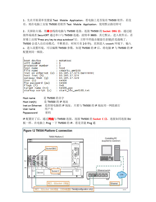
1、先在开始菜单里搜索Test Mobile Application,看电脑上是否装有TM500软件,若没有,则在电脑上安装TM500的软件Test Mobile Application,使用默认路径即可2、关掉防火墙,用串口线将电脑与TM500连接,连接TM500的Socket DBG口,通过超级终端或者SecuriCRT通过串口与TM500连通,波特率9600,其它默认。
进入软件后,若屏幕上出现”Press any key to stop autoboot”后,立即不停敲击键盘任意键(若是敲晚了,TM500会进入自启动模式,不断重启,时间只有2-3秒)。
直到进入vxwork环境下,输入c,进入设置环境,可以编辑TM500参数。
知道TM500的IP后,将电脑IP与TM500的IP 配置到同一频段。
Host name 是TM500的名字Host inet(h) 是TM500的IP地址Inet on Ethernet 是控制电脑的IP地址,只要与TM500的IP地址同一网段就行User name 用户名Ftppassword 密码IP配置好了后,通过网线与TM500连接,连接TM500的Socket C口,连接如同连接DU 板一样。
在电脑上Ping一下TM500的IP,看是否能Ping通TM500每一次上电后,都会自动通过网络从服务器下载软件,所以TM500运行时,一定要将FileZilla Server Interface 打开,将本机作为服务器。
新建用户名与上面的User name一样,密码与上面的Ftppassword一样。
然后打开Shared Folders 共享路径。
共享路径为:c:\Program Files\Aeroflex\TM500\[Release Name]\ppc_pq\public\ftp_root。
将所有的文件和属性都设置为可用,点击“Set as home dir”将其设置为默认路径,在General选项卡里设置密码Ftppassword,如图所示:TM500的射频卡可能需要升级,升级完后,需要断电重启,至少断电30秒。
Issue DateINSTALLATION INSTRUCTIONSAccessory Application Publication No.Honda Dealer: Please give a copy of these instructions to your customer.© 2014 American Honda Motor Co., Inc - All Rights Reserved.PARTS LIST0SR73-HL5-100FULL POLY TIP OUT WINDSCREEN (OPTICAL)P/N 0SR73-HL5-100SXS500M 2USE AND CARE INFORMATION•Check the accessory mounts frequently and retighten if necessary.•Replace this accessory with a new one if it is damaged or discolored excessively.•When this accessory becomes dirty, rinse it thoroughly with cool water to remove loose dirt, and then wash with warm soapy water and a clean cloth or sponge.•Do not use a brush to clean this accessory as it may scratch the surface.•Never use petroleum solvents such as gasoline,thinner, or benzene to clean this accessory. Also do not use acid or alkaline cleaners.No.Description Qty (1) Windscreen 1(2) Clamp 2(3) Cam lock 2(4) Hinge arm, left1(5) Hinge arm, right 1(6) 6 x 40 mm socket bolt 2(7) 6 x 30 mm socket bolt 2(8) 6 x 20 mm socket bolt 2(9) 6 mm lock nut (small)6(10)1/4 inch lock nut (large)2(11) Small washer 2(12) Large washer 4(13)25 mm collar2(14) Knob2Mll 14948June 2014(2)(5)(9)(10)(11)(12)(13)(14)(4)(1)NOTE•Remove and discard the rubber shipping spacer fromthe cam locks before installation of this accessory.TOOLS AND SUPPLIES REQUIREDHex wrench (4 and 6 mm)Torque wrenchOpen-end wrench (8 and 10 mm)TORQUE CHARTTighten all screws, bolts, and nuts to their specified torque values. Refer to the Service Manual for the torque values of the removed parts.ItemN·m kgf·m Ibf·ft 6 mm socket bolt 70.7 5.26 x 30 mm socket bolt 10.10.96 mm nut70.75.2Stud10.10.9SHIPPING SPACER(DISCARD)© 2014 American Honda Motor Co., Inc - All Rights Reserved.0SR73-HL5-100INSTALLATION1. Open the cam lock and insert a 6 x 40 mm boltthrough the hole in the bottom of the cam lock.2. Install a collar onto the end of the bolt.3. Insert the assembled bolt and collar through themounting bracket on the top of the windscreen.4. Install a small washer and 6 mm lock-nut to the endof the bolt and tighten to them to the specification in the torque chart.9. Adjust cam lock tension by rotating the threaded armclockwise to tighten, counter-clouckwise to loosen.THREADED ARM5. Repeat Steps 1 through 4 for the cam lock andbracket on the opposide side of the windscreen.6. Open both cam locks along the top of thewindscreen.7. Place the windscreen onto the vehicle centeredbetween the A-pillars, seating the bottom of the windscreen on the base of the hood.8. Align the cam locks around the cab A-pillar bars andsnap the arms closed.CAM LOCK6 x 40 mm BOLTCOLLARMOUNTING BRACKETSMALL WASHER6 mm LOCK-NUTA-PILLARCAM LOCK© 2014 American Honda Motor Co., Inc - All Rights Reserved.0SR73-HL5-100KNOBCLAMPLARGE WASHERLARGE WASHER16. Place a large washer on the end of the knob andpass it through the hinge arm.17. Place a second large washer on the knob betweenthe hinge arm and the clamp.18. Thread the knob stud into the nut in the clamp andthen hand tighten it, plus one full turn. Do not over-tighten the stud.19. Repeat Steps 13 through 18 for the clamp and hingearm on the right side of the windscreen. 6 mm LOCK- NUT20. To adjust windscreen position, open the arms on thecam locks and loosen the clamp screws. Slide the windscreen up or down the A-pillars and retighten all hardware once the desired position is achieved.STUD。
OPERATION MANUALT1201VOR, ADF, ILS DISCRETE FUNCTIONINTERFACE UNITMANUAL NUMBER:06-1201-01E6-1201-01REVISION:0DATE:03/26/2007WARNING: INFORMATION SUBJECT TO EXPORT CONTROL LAWSThis manual may contain information subject to the International Traffic in Arms Regulation (ITAR) or the Export Administration Regulation (EAR) which may not be exported, released, or disclosed to foreign nationals inside or outside of the United States without first obtaining an export license. A violation of the ITAR or EAR may be subject to a penalty of imprisonment and/or fines under 22 U.S.C.2778 of the Arms Export Control Act or section 2410 of the Export Administration Act. Include this notice with any reproduced portion of this document.This document is proprietary to Aeroflex, and is not to be reproduced or otherwisedisseminated without the written consent of Aeroflex.400 New Century Parkway – New Century, Kansas – 66031Telephone: (800) 237-2831 / (913) 764-2452 Fax: (913) 782-5104ELECTROSTATIC DISCHARGE GENERAL WARNINGS FOR ALL EQUIPMENTCAUTION:THIS EQUIPMENT MAY CONTAIN ELECTROSTATIC DISCHARGE (ESD) SENSITIVE COMPONENTS. TO PREVENT ESD SENSITIVE EQUIPMENT FROM POSSIBLEDAMAGE, OBSERVE THE FOLLOWING PRECAUTIONS WHEN HANDLING ANY ESDSENSITIVE COMPONENTS, OR UNITS CONTAINING ESD SENSITIVECOMPONENTS:a. Maintenance or service personnel must be grounded though a conductive wrist strap, or a similargrounding device, using a 1 MΩ series resistor for equipment protection against static discharge, and personal protection against electrical shock.b. All tools must be grounded (including soldering tools) that may come into contact with theequipment. Hand contact will provide sufficient grounding for tools that are not otherwisegrounded, provided the operator is grounded through an acceptable grounding device such as a wrist strap.c. Maintenance or service of the unit must be done at a grounded, ESD workstation.d. Before maintenance or service of the equipment, disconnect all power sources, signal sources,and loads connected to the unit.e. If maintenance or service must be performed with power applied, take precautions againstaccidental disconnection of equipment components. Specifically, do not remove integratedcircuits or printed circuit boards from equipment while the equipment has power applied.f. All ESD sensitive components are shipped in protective tubes or electrically conductive foam.The components should be stored using the original container/package when not being used or tested. If the original storage material is not available, use similar or equivalent protectivestorage material.g. When ESD sensitive components are removed from a unit, the components must be placed on aconductive surface, or in an electrically conductive container.h. When in storage or not being repaired, all printed circuits boards must be kept in electricallyconductive bags, or other electrically conductive containers.i. Do not unnecessarily pick up, hold, or directly carry ESD sensitive devices.Failure to comply with these precautions may cause permanent damage to ESD sensitive devices. This damage can cause devices to fail immediately, or at a later time without apparent cause.Aeroflex Operation ManualREVISION HISTORY BY DRAWING NUMBER MANUAL: T1201 VOR, ADF, ILS Discrete Function Interface UnitREVISION: 0 – March 26, 2007REV. REV._LEVEL DRAWING NO. LEVEL NO.DRAWINGTable of Contents 00Section I 00Section II 00Section III 00Section IV 00Section V 00Aeroflex Operation ManualTABLE OF CONTENTSSECTION IGENERAL INFORMATIONSECTION PAGE NUMBER 1.1 INTRODUCTION...............................................................................................1-11.2 EQUIPMENTDESCRIPTION............................................................................1-1CHARACTERISTICS...................................................................1-11.3 TECHNICAL1.3.1 General..............................................................................................................1-1Simulator.............................................................................................1-11.3.2 Antenna1.4 UNITSACCESSORIES REQUIRED........................................................1-2ANDEQUIPMENT..................................................................................1-21.5 OPTIONALINFORMATION................................................................................1-31.6 RELATEDSECTION IIINSTALLATIONINFORMATION...............................................................................2-12.1 GENERAL2.2 UNPACKING AND INSPECTION OF EQUIPMENT.........................................2-12.3 EQUIPMENT SETUP........................................................................................2-1SECTION IIIOPERATION3.1 INTRODUCTION...............................................................................................3-1FUNCTIONS...................................................................................3-13.2 CONTROLFront Panel........................................................................................3-1–3.2.1 Control–Rear Panel.........................................................................................3-53.2.2 ControlSECTION IVTHEORY OF OPERATIONSCIRCUIT THEORY..........................................................................4-14.1 GENERALAmp Board..............................................................................................4-14.1.1 AudioSimulator Board..................................................................................4-14.1.2 AntennaSECTION VMAINTENANCEINFORMATION......................................................................5-15.1 MAINTENANCESECTION IGENERAL INFORMATION1.1 INTRODUCTIONThis manual contains information relative to the physical, mechanical and electrical characteristics of the Aeroflex Model T1201 Discrete Function Interface Unit, (DFIU) PN: 01-1201-00.1.2 UNITS AND ACCESSORIES SUPPLIEDTh T1201 DFIU is designed to operate and test ARINC 700 Series ILS (ARINC 710), VOR/MB (ARINC 711) and ADF (ARINC 712) Line Replaceable Units. Power control and protection, as well as all necessary discretes and monitoring points are provided. Magnetic overlays for each applicable LRU are available which connect either the ILS, VOR, or ADF receivers to the T1202. ARINC 429 transmissions and reception to and from the LRU’s is provided by the companion T1200 Control Display Unit (CDU) via a rear panel interface connector. The T1201 DFIU also provides an ATE interface port and a special Collins Radio Interface similar to RS-232. A self-contained Antenna Simulator provides the sense and loop signals required for testing ADF receivers.1.3 TECHNICAL CHARACTERISTICS1.3.1 GENERALKg)(6.82lbs.Weight: 15cm)(30.86in.Height:12.15(48-26cm)in.Width:19.00Depth : 9.00 in. (22-86 cm)Power Requirements : 27.5VDC @ 2 AmpsAmps2155VAC/400Hz@Operating Temperature : +10 to +45 deg. C1.3.2 ANTENNA SIMULATOR:KHz190-1750RangeFrequencyInput Impedance : 50 Ohms (unbalanced)Output Impedance : 78 Ohms +/- 5%Sense Channel OutputAttenuationAmplitudeinputtheFactor (Effective Height) .03timesLoop Channel OutputsAttenuation Factor : .023 times input at 190 KHzatKHz577input.038times1750KHzattimesinput.023Accuracy : +/- 2 dBLoop Output AmplitudeMatch at 45° Relative.25dB: +/-BearingAntenna Mount Top/BottomFunction : Top - Sine & Cosine in phase first quadrantCosine180° out of phase first quadrant&Bot-Sine1.4 UNIT AND ACCESSORIES SUPPLIEDThe Aeroflex Model T1201 DFIU, PN: 01-1201-00, consists of the main test panel and the following accessories:ITEM DESCRIPTION P/N1 T1201 CD Operation Manual E6-1201-012 115V/400Hz Power Cable 55-2406-001.5 OPTIONAL EQUIPMENTThe following items are available as optional equipment with the T1201 DFIU. They must be ordered separately.ITEM DESCRIPTION P/N1 T1201-01 VOR/MB Interface Cable 55-1201-012 T1201-02 ILS Interface Cable 55-1201-023 T1201-03 ADF Interface Cable 55-1201-034 Test Point Overlay – ADF-700 58-1169-005 Test Point Overlay – VOR-700 58-1169-016 Test Point Overlay – ILS-700 58-1169-021.6 RELATED INFORMATIONFor information regarding the T1201-01 (VOR/MB), T1201-02 ILS and T1201-03 (ADF), T1201-04 (MMR) Interface Cables, refer to their individual operation manuals. When referencing the T1201-04 (MMR) cable also consult the associated test unit the MMR Test Fixture, Manual number 06-0997-00. The part numbers for these Interface Cable manuals are as follows :INTERFACE CABLE MANUAL P/NT1201-01 C6-1201-01T1201-02 C6-1201-02T1201-03 C6-1201-03T1201-04 C6-1201-04SECTION IIOPERATION2.1 GENERAL INFORMATIONThis section contains information relating to the unpacking, inspection and setup of the T1201 DFIU accessories.2.2 UNPACKING AND INSPECTION EQUIPMENTCarefully remove the T1201 DFIU and accessories from the packing box. Make a visual inspection of the unit for evidence of damage incurred during shipment. If a claim for damage is to be made, save the shipping container to substantiate the claim. When all equipment has been unpacked, return the packing material to the container for future use in storing or shipping the equipment.2.3 EQUIPMENT SETUPThe T1201 DFIU may be installed free standing on a workbench table top or mounted in a 19-inch equipment rack using the integral rack mounting ears.Connect 28VDC power to the banana jack/binding posts (J16) at the rear of the T1201.Connect 115VAC/400Hz power to the receptacle (J5) at the rear of the T1201 using the power cordJPN: 55-2406-00, provided with the test set.* * * NOTE * * *The power cord provided is left unterminated at one end to accommodate wiring to your own particular 115VAC supply. The wires should be connected as follows :BLK Wire – 115VAC-400Hz HotWHT Wire – 115VAC/400Hz NeutralGRN Wire – 115VAC/400Hz GroundConnect a T1200 CDU to the T1200 Interface connector (J4) at the rear of the T1201 using the T1200 DFIU Cable, PN: 55-2401-00, supplied with the T1200.The LRU is connected to the T1201 via the T1201-01 (VOR/MB), T1201-02 (ILS) or T1201-03 (ADF) Interface Cable, PN: 55-1202-01, -02,or –03, respectively. Install the appropriate magnetic test point overlay (see section 1.5) to the T1201’s test point field on the front panelIMPORTANTRefer to the appropriate Component Maintenance Manual (CMM) to test procedure for additional test equipment set up procedures.SECTION IIIOPERATION3.1 INTRODUCTIONThis section contains the basic operating procedure for the T1201 DFIU.3.2 CONTROL FUNCTIONSThe T1201 provides all the necessary signals for testing the ARINC 700 Series VOR, ILS and ADF Navigation Systems. The following is a description of each of the controls provided on the DFIU.NOTESome additional controls may be installed on the LRU Interface Cables.3.2.1 CONTROLS – FRONT PANEL (Figure 3-1)(1) DFIU POWER ON/OFF Switch (S18) The T1201 power requirements are provided by anexternal 28VDC source connected to the T1201through a set of banana jack/binding posts (J16) onthe rear panel. The power to the DFIU is turned ONor OFF with a DPST toggle switch.(2) DFIU POWER Fuse (F2) Provides over-current protection for the T1201circuitry.internal(3) DFIU POWER Lamp (DS5) Illuminates when the DFIU 28VDC power isswitched on by S18.(4) UUT POWER ON/OFF Switch (S17) The Unit Under Test power requirements areprovided by an external 115VAC/400Hz sourceconnected to the T1201 through a 3-conductorpower receptacle (J5) on the rear panel. The powerto the UUT is turned ON or OFF with a DPST toggleswitch.(5) UUT POWER Fuse (F1) Provides over-current protection for the unit undertest.(6) UUT POWER Lamp (DS4) Illuminates when the UUT 115Vac/400Hz power isswitched on with S17.(7) CURRENT MONITOR Jacks (J12 & J13) These test jacks allow the user to calculate thecurrent drawn by the UUT by measuring the ACvoltage dropped across a precision 1 ohm resister(R1) in series with the connection to the UUT powerinput (1 volt + 1 amp).(8) LRU AC OUT Jacks (J14 & J15) These test jacks allow the user to monitor the115VAC output from the UUT (VOR & ILS LRU’Sonly).(9) LRU Connector (J1) 156-pin DL connector used to connect with the VOR,ISL, and ADF LRU Interface Cables, i.e. T1201-01,T1201-02 and T1201-03.(10) 429 INPUT BUS Jacks (J203 & J204) Two ¼” stereo phone jacks allow monitoring of thetwo ARINC 429 output buses from the UUT.(11) 429 OUTPUT BUS Jacks (J205 & J206) Two ¼” stereo phone jacks allow monitoring of thetwo ARINC 429 output buses from the UUT.(12) DATA SOURCE Switch (S11) Controls the discrete input pin of the UUT forselecting either ARINC 429 input port A or B.(13) RCVR AUDIO OUT Jacks (J10 & J11) Allows monitoring of the VOR, ILS and ADFReceiver audio outputs.(14) SDI CODE Switch (S16) Allows changing the SDI input straps to eachpossible SDI code (0-3).(15) AUDIO LOAD Switch (S15) Allows selecting various loads for the VOR, ILS orADF audio outputs. The AMP position connects theaudio output to the internal amplifier and speaker.Control Controls the volume of the speaker.(16) VOLUME(17) A/G LOGIC Switch (S10) Controls the AIR/GROUND discrete input to theUUT. The input is connected to ground on the ONposition and is open in the OFF position.(18) FUNC TEST DISC Switch (S9) Controls the FUNCTION TEST discrete in put to theUUT. The input is connected to ground in the ONposition and is open in the OFF position.(19) TEST POINT Field Provides monitoring capability for the sixty pincorresponding to the top plug of the LRU ARINC 600connector. Magnetic overlays are available whichdefine each point for user convenience.(20) TUNE FUNCTION TEST Switch (S1) Controls the TUNE/FUNCTION TEST INHIBITdiscrete input (MP1C) on the ILS Receiver. Theinput is connected to ground in the ON position andis open in the OFF position.(21) LOC/GS DATA Switch (S12) Allows connecting or disconnecting the “LOC/GSInterrupt Data Program pin” (MP3A) to the “LOC/GSData Control Common” (MP3B) on the ILS Receiver.(22) SPEAKER (LS101) A 45 ohm speaker for reproducing the receiveraudio from the UUT.(23) INNER MARKER Lamp (DS1) White lamp which illuminates when the Inner (Fan)Marker output from the Marker Beacon Receiverlow.goes(24) MKR AUDIO LOAD Switch (S14) Allows selecting various loads for the MarkerBeacon Receiver audio output. The AMP positionconnects the audio output to the internal amplifierspeaker.and(25) MIDDLE MARKER Lamp (DS2) Amber lamp which illuminates when the MiddleMarker output from the Marker Beacon goes Low. (26) MKR AUDIO OUT Jacks (J8 & J9) Allows monitoring of the Marker Beacon Receiveroutput.audio(27) OUTER MARKER Lamp (DS2) Blue lamp which illuminates when the Outer Markeroutput from the Marker Beacon Receiver goes low. (28) SENSE Switch (S7) Controls the Hi/Lo Sensitivity discrete input (MP9D)on the Marker Beacon Receiver. The input isconnected to ground in the HI position and is open inthe LO position.(29) INHIBIT Switch (S8) Controls the Marker Function Inhibit discrete input(MP2D) on the Marker Beacon Receiver. The inputis grounded in the ON position and is open in theposition.OFF(30) QEC STRAP Switch (S2-S6) Five toggle switches control the Quadrantal ErrorCorrection inputs to the ADF Receiver. Each inputis connected to the “QEC COMMON” pin (MP9C) inthe CLOSED (DOWN) position and is open in theUP position.(31) SIMULATED BEARING Control (B1) Planetary drive which controls the angular setting ofthe internally mounted goniometer. The goniometercontrols the sine and cosine ADF antenna inputs tothe ADF Receiver.(32) ADF Antenna Connector (J17) 16 pin connector used to mate with the ADFAntenna connector on the T1201-03 ADF InterfaceCable.(33) RF INPUT Connector (J301) BNC connector used to input the RF signal to theADF Antenna Simulator for producing the sense andloopsignals.(34) ANTENNA MOUNT Switch (S13) Controls the Antenna Mount Top/Bottom discreteinput (MP13C) on the ADF Receiver. The input isconnected to ground in the TOP position and is openin the BOTTOM position. Also used to cause a 108°phase reversal of the sine output from the ADFSimulator.AntennaFig. 3-1: T1201-Controls – Front Panel3.2.2 CONTROLS – REAR PANEL (Fig. 3-2)(1) 24VDC Power Input Jacks A set of banana jack/binding post used to connectthe DFIU to a 24VDC power source.(2) 115VAC/400Hz Power Receptacle (J5) Used to connect the DFIU to a 115VAC/400Hzpower source via the detachable 3-conductor powercord.(3) REMOTE SELECTOR Switch This switch has no current function and is notoperational.(4) T1200 INTERFACE Connector (J4) A 37-pin female D connector used to interface theDFIU to a T1200 CDU.(5) COLLINS TEST Connector (J3) A 25-pin female D connector used to gain access tovarious test points from the UUT top plug. SeePN: 02-1201-00 for wiring information.(6) ATE INTERFACE Connector A 96-pin DL connector wired to the DFIU’s test pointboard and to the LRU interface connector. It is alsowired to several monitor points on the DFIU whichprovide additional ATE connections not covered bythe test point board. See PN: 02-1201-00 forinformation.wiringFig. 3-2 ; T1201 Controls – Rear PanelTHEORY OF OPERATION4.1 GENERAL CIRCUIT THEORYSome active circuit is contained on printed circuit boards within the T1201. The following is a brief description. 4.1.1 AUDIO AMP BOARDThe Audio Amp Board, PN: 20-5573-00, is mounted to the inside of the front panel beside the Test Point Board. It is used to provide the selectable load for the receiver’s audio output and to provide a variable amplified output to drive the panel mounted speaker.4.1.2 ANTENNA SIMULATOR BOARDThe Antenna Simulator Board, PN: 20-5616-00, is mounted to the inside of the front panel just above the power switches. It is used to drive the sense and loop antenna of the ADF Receiver.The sense and loop outputs are derived from an RF source (190-1750 KHz) applied at the RF INPUT BNC Connector (J303). The input impedance is approximately 50 ohms.The signal level at the sense output is determined by voltage divider R309 and R310, transformer T305 and series resistor R311.The sine and cosine loop output signals are the result of coupling the RF signal through a goniometer, whose angular position is determined by the rotational placement of a graduated planetary driver mechanism attached to its shaft. Amplitude calibration is accomplished with gain adjustment potentiometers R313 (COS channel) andR314 (SIN channel).MAINTENANCE5.1 MAINTENANCE INFORMATIONTo assist in the maintenance of the Aeroflex Model T1201 Discrete Function Interface Unit, bills of material, assembly drawings, schematics and a test procedure are included in the T1201 Maintenance Manual (P/N 06-1201-00 for hard copy, E6-1201-00 for CD) available separately from Aeroflex.。
简爱比作花的作文你们读过《简爱》这本书吗?我可喜欢啦!在我心里,简爱就像一朵无比特别的花。
简爱,她没有让人惊艳的外表,也没有高贵的出身,可她有着一颗勇敢而坚定的心。
这不就像那小小的野菊花吗?野菊花生长在山坡上、田野边,没人精心照料,却能顽强地绽放。
记得书里简爱小时候,在舅妈家受尽了欺负。
“哎呀,那日子得多难熬啊!”可是她没有低头,没有放弃。
就像那在狂风中依然挺立的花朵,无论风怎么吹,都不会倒下。
在寄宿学校里,条件艰苦,简爱也没被困难打倒。
她努力学习,不断提升自己。
这难道不像那努力吸收阳光雨露的花苞,一点点积蓄力量,等待绽放吗?后来,简爱成为了家庭教师,遇到了罗切斯特先生。
她没有因为罗切斯特的财富和地位而迷失自己,而是坚持自己的爱情原则。
“哇,这得需要多大的勇气啊!”这多像那朵在百花丛中,依然保持独特的花,不随波逐流,坚守自我。
有一次,我和小伙伴们讨论《简爱》。
“我觉得简爱太倔强了!”一个小伙伴说。
“才不是呢!”我立刻反驳道,“那是她的坚持,她知道自己想要什么。
”“可是她也吃了好多苦呀。
”另一个小伙伴感叹道。
“那又怎样?”我激动地说,“就像花朵经历风雨才能开得更灿烂呀!”简爱的爱情之路也充满了波折。
当她发现罗切斯特先生已有妻子时,毅然离开了他。
这是多么艰难的决定啊!但她就像那果断舍弃残枝败叶的花朵,只为了追求真正的美丽和完整。
最终,简爱获得了属于自己的幸福。
这就如同那历经磨难终于盛开的花朵,散发着迷人的芬芳。
简爱,她不就是一朵在逆境中绽放的花吗?无论环境多么恶劣,她都能绽放出属于自己的光芒。
朋友们,简爱这朵花是不是让你们也深受感动呢?反正我觉得,她就是我心中最了不起的那朵花,永远绽放,永不凋谢!。
新闻稿For more information, contact:Debra Seifert James E. De BroeckDebra Seifert Communications LLC Aeroflex Incorporated(503) 626-7539 (316) 522-4981debra@ jim.debroeck@FOR PRINT AND ONLINE RELEASE: February 27, 2012艾法斯TM500 LTE测试移动终端新增Cat5用户设备仿真性能作为事实行业标准的测试移动终端,正通过使运营商能够在其LTE网络中验证更高数据速率性能而继续保持其领先地位西班牙巴塞罗纳全球移动通讯大会(MWC)—1号厅1B14展位—2012年2月27日—艾法斯控股公司(Aeroflex Holding Corp.,纽交所代码:ARX)旗下的全资子公司艾法斯有限公司(Aeroflex Limited)日前宣布:其TM500 LTE测试移动终端作为第一款可仿真LTE 5类(Cat5)用户设备(UE)的测试移动终端,可使运营商验证其网络的运行状况,并可使设备供应商去证明其eNodeB(LTE基站)针对Cat5手机和终端在更高数据速率时的性能。
TM500测试移动平台已经被全世界所有重要基础设施供应商及绝大多数毫微微蜂窝供应商所使用。
Cat5是对LTE用户设备能力的一种分类,它为上行链路(UL)和下行链路(DL)都提供了增强的数据速率。
在良好的信道条件下使用一个20 MHz的带宽和频分双工(FDD),由于增加了对4x4 多输入多输出(MIMO)的支持,可以在下行链路上实现300 Mbps的数据传输速率。
在上行链路上,除了通过利用早先的正交相移键控(QPSK)和16阶正交幅度调制(16QAM),还可通过利用64阶正交幅度调制(64QAM)来提高数据速率,达到75Mbps。
而且,Cat5在下行链路中引入了有限缓冲速率匹配,可用来为高性价比的手机提供限制内存的需求。
TM500 Test Mobile移动测试系统简介–工业标准
为满足新型蜂窝通信设备不断发展的需求,基站一般要在手机推出很早之前就位。
但没有手机如何测试基站呢? Aeroflex为此推出了TM500移动测试系统。
需要HSPA+手机UE测试仪吗? 可选择TM500。
需要性能达到300Mbit/s的LTE UE测试仪吗? 可选择TM500。
需要支持LTE开发测试、供容量测试解决方案重用的多UE测试仪吗? 同样可以选择TM500!
各大基础设施供应商和毫微微蜂窝基站制造商在其整个开发过程中均采用TM500。
为什么? 因为它已成为3GPP认证、验证和优化的行业标准。
从HSDPA到HSUPA、HSPA+直至LTE,TM500具有所有移动终端性能高级测试功能。
而且,TM500产品路线图已步入行业发展最新进程,帮助Aeroflex客户及时推出新产品。
测试一个基站要比测试单部手机困难得多。
需要优化调度算法,而且需要测试基站承受的负载。
TM500 Multi-UE 测试仪可在设计初期测试复杂的调度程序和负载容量,有助于为网络运营商提供可靠、灵活和高性能解决方案。
Aeroflex Test Mobiles 移动测试系统减少手机EU控制,具有灵活的配置能力,可为基础设施工程师提供所需详细测试数据,加快工程问题的诊断。
最新推出基于LTE等新技术的尖端移动测试系统可为3GPP最新功能提供测试支持。
技术移动测试系统产品
LTE TM500 LTE
TM500 LTE Multi-UE
HSPA+ TM500 HSPA+
HSUPA TM500 HSUPA TM500 HSUPA Multi-UE
HSDPA TM500 HSDPA TM500 HSDPA Multi-UE
7100 LTE 综合测试仪
用于测试无线设备RF、基带和协议层,支持多种无线接入技术的LTE网络仿真器。
●LTE FDD与TDD信令网络模拟
●开发与Call-Box工作模式
●适用于广泛的RF测试
●完整的RF参数测量套件
●丰富的预配置36.521 RF测试例
●TTCN-3支持
●频率范围达6 GHz,涵盖所有LTE频段和带宽
●协议记录与分析
●支持多小区与Inter-RAT切换
●多种无线接入技术(RAT) 测试: LTE、eHRPD、1xRTT、GERAN、HSPA和TD-SCDMA
●功能测试
●端到端IP分组数据测试
●集成衰落/AWGN选件
●MIMO 4x4 –即将发布
●采用远端API自动测试
●嵌入基于Windows® XP的控制器PC
●先进的12"触摸屏GUI
Aeroflex 7100 LTE 综合测试仪为UE 芯片组和终端提供设计、开发和测试工具,满足3GPP Rel-8 标准的要求。
7100 LTE 综合测试仪的用户包括RF开发人员、协议栈开发团队、集成测试团队和预认证实验室,以及基于LTE标准进行子系统开发和集成设计的部门。
7100还支持生产线末端测试,可在大规模生产线上进行抽样测试。
7100具有易用、综合测试功能、快速和拥有成本低等优点,可使这些团队从中受益。
7100模拟E-UTRAN和EPC (增强型分组核心),为LTE终端提供真实的测试环境。
测试程序控制仿真网络的特性,可创建大量重复使用的测试情景。
测试仪可集成衰落模拟器和加性高斯白噪声(AWGN) 源选件,在实验中建立实际环境下的信号条件。
LTE开发模式支持详细协议记录与分析
针对协议栈的开发和集成,7100开发模式提供先进的L1、L2和L3协议层记录功能,解决开发过程中出现的问题。
信息过滤与搜索功能便于导航。
利用情景向导(Scenario Wizard),通过简单的拖放图形界面可轻松创建采用所有LTE子层的定制测试情景。
LTE在有讯号模式支持功能和应用测试
测试仪具有用来描述LTE移动设备性能的所有关键测量功能,无论无线电接口,还是协议栈,包括PCDP 和IMS层。
利用7100网络仿真模式,可以准确评估设备的端到端性能,以及正确的空闲模式和连接模式行为。
在有讯号(Call Box) 模式便于测试活动管理人员定义测试顺序并利用7100触摸屏GUI进行测试。
LTE物理层测试与RF参数测试
7100矢量信号分析仪/矢量信号发生器(VSA/VSG模式) 可对LTE发射机和接收机性能进行综合RF参数测试。
FDD和TDD工作模式可选择大量基于3GPP 36.521定义的LTE RF测试例。
实际条件下进行数据流量测试
7100集成LTE基带衰落、AWGN和内置RRM测试功能,可模拟实验室环境下各种实际信号条件。
采用创新的基于软件定义的无线电技术不仅有助于降低测试环境增加衰落模拟测试的成本,而且可在设计过程中提前完成测试,减少后期重新设计的费用,降低内场实验成本并缩短时间。
切换与多种无线接入技术测试
7100 LTE数字无线电测试仪可模拟无线接入技术之间的系统选择以及系统重选程序。
LTE与任何支持的无线标准之间的切换可通过一台7100无线电测试仪来完成。
系统扩展功能还支持非LTE标准、2G和3G 之间的Inter-RAT切换。
自动化测试开发环境
7100配有开放式应用编程接口(API),便于全面控制测试脚本的开发。
7100 BSE命令行界面可以精细控制L1/L2层,以及整个协议栈的操作。
BSE应用编程界面通用功能可用来配置和控制RRC/NAS层、生成测试情景、捕获参数测量结果并控制记录。