东方日升72片系列单晶组件BOM
- 格式:xlsx
- 大小:27.08 KB
- 文档页数:4
光伏发电项目建议书【篇一:光伏农业项目建议书】xxx省xxx市xxx县林口铺并网光伏发电项目工程光伏生态产业规划提案编制人:xxx能投生态环境科技有限公司编制时间:2015年6月18日目录1.2.3. 项目名称........................................................................................................ .................................. 2 项目概述........................................................................................................ .................................. 2 项目意义........................................................................................................ . (3)3.1.3.2.3.3.3.4.4. 发展趋势 ....................................................................................................... .......................... 3 可持续再生能源发展 ....................................................................................................... ...... 3 光伏产业中的土地利用——光伏农业 ................................................................................. 5 结语 ....................................................................................................... .................................. 7 技术推广区域现状及前景 ....................................................................................................... . (7)4.1.4.2. 推广区域现状 ....................................................................................................... .................. 7 发展前景 ....................................................................................................... (12)5. 国内外研究现状及案例分析 (12)5.1.5.2.5.3.5.4.5.5.5.6. 案例一:内蒙古 ....................................................................................................... ............ 13 案例二:耳其科尼亚省科尼亚,位于安纳托利亚高原中南部农业区 ............................ 13 案例三:呈贡晨农生态园 ...................................................................................................13 案例四:xxx万家欢蓝莓山庄 .......................................................................................... 14 案例五:嵩明晨农农博园 ...................................................................................................15 案例分析 ....................................................................................................... ........................ 16 6.7. 项目定位........................................................................................................ ................................ 16 经营模式........................................................................................................ .. (17)7.1.7.2.7.3.7.4. 集光伏大棚果蔬(人生果)种植、粗加工、深加工、销售为一体 ................................ 17 以牧草种植、畜牧养殖为一体 ........................................................................................... 17 以农事参与与体验为一体 ...................................................................................................18 建盖光伏农业科普展示区,以观光和科普教育为一体 (20)8. 社会效应........................................................................................................ .. (20)9. 经济效应........................................................................................................ .. (20)1. 项目名称xxx省xxx市xxx县林口铺并网光伏发电项目工程光伏生态产业规划提案2. 项目概述作为光伏生态产业示范园项目,便是将太阳能发电、现代技术(农、林、牧业)、高效、有机的结合在一起。

光伏供电在5G通信基站建设中的应用研究发布时间:2023-03-07T09:25:57.010Z 来源:《中国建设信息化》2022年10月20期作者:王军伟[导读] 本文主要对光伏供电在5G通信基站建设中的应用进行分析与研究,以供同仁参考。
王军伟中国铁塔股份有限公司广东省分公司摘要:本文主要对光伏供电在5G通信基站建设中的应用进行分析与研究,以供同仁参考。
关键词:5G基站;电力供应;光伏供电;方案研究一、前言随着5G大规模应用普及,5G基站的覆盖场景也不断拓展,其建设形式更多的由传统的宏基站、室分、微基站、可附建的资源更广等,而一直以来基站的建设就面临着征址难、基站功耗大等系列问题。
为了更好地解决基站功耗大的问题,光伏发电与电能相结合,可以解决光伏发电输出功率不稳的问题,并能平滑电力输出,提高光伏发电的质量。
二、在5G通信基站建设中光伏供电建模光伏组件是太阳能转化为电能的核心部件,由若干单体电池串、并联连接和严密封装成组件,太阳能转化为电能的效率取决于光伏组件原材料及技术参数要求。
光伏组件从原材料上分为单晶光伏组件和多晶光伏组件,符合通信基站供电的电池片数量一般有48片、60片、72片、120片,组件容量(峰值功率Wp)为250~445Wp。
一定数量光伏组件按照系统的总功率需求组合成太阳能方阵为通信基站系统供电,太阳能方阵总功率计算如下:太阳能方阵总功率QP=负载功率QW×用电时间(HE)/日照峰值时间(HS)/损耗系数R式中,负载功率QW由通信基站设备负载功耗确定;用电时间根据夜间(HE)(阴雨天最低日照时间)确定;日照峰值时间(HS)根据基站所在位置的日照时长确定;损耗系数R默认按照0.75取值。
三、在5G通信基站建设中光伏供电系统组成光伏发电是利用半导体界面的光伏效应将光能直接转变为电能,通过计算用电时间和充放电时间,按照基站功耗需求适当配置由光伏组件组成的太阳能方阵进行发电及储能电池组,从而实现不间断的为基站进行供电,其组成如图1所示。

东方日升(浙江)新能源有限公司在义乌经济技术开发区投资建设年产5GW 高效太阳能电池组件生产项目可行性研究报告2020 年7 月1目录1总论 (4)1.1建设单位情况 (4)1.2项目概况 (5)1.3项目建设背景 (5)2建设规模与产品方案 (8)2.1建设规模 (8)2.2产品方案 (8)3建设方案 (9)3.1设备方案 (9)3.2工程方案 (11)3.3主要原辅材料供应 (11)3.4公用辅助工程 (11)4节能分析 (13)4.1能耗指标分析 (13)4.2能耗指标计算 (13)4.3节能措施 (13)5项目实施进度 (16)26投资估算与资金筹措 (17)6.1投资估算 (17)6.2总投资估算 (17)6.3项目资金筹措 (17)7项目风险分析 (18)7.1风险识别和分析 (18)7.2风险防范对策 (19)31 总论1.1建设单位情况建设单位:东方日升(浙江)新能源有限公司法定代表人:杨钰法定住所:浙江省义乌市稠江街道杨村路288 号三楼注册资本:5,000 万元公司类型:有限责任公司经营范围:新能源科技研发;太阳能电池组件、家用电器、灯具、橡塑制品、电子产品的加工销售;太阳能发电工程总承包;电力、新能源、节能技术研发、成果转让;合同能源管理服务;货物进出口、技术进出口。
(除依法须经批准的项目外,凭营业执照依法自主开展经营活动)。
东方日升(浙江)新能源有限公司成立于2020 年 5 月,是东方日升新能源股份有限公司(以下简称“东方日升”)全资子公司。
东方日升2009 年5 月完成股份制改造,2010 年9 月正式在深交所挂牌上市。
东方日升是一家专业从事光伏并网发电系统、光伏独立供电系统、太阳能电池片、组件等的研发、生产和销售的高新技术企业。
目前,东方日升建有独立的国家级光伏实验室。
公司获得国际CNAS 认证,可按照IEC61215、IEC61730-2、UL1703 进行54 个项目测试。
宝应县射阳湖镇鹅村村岗东30MW 渔光互补光伏电站项目初步设计可研编号:GCL/SUN-GF215C主编单位:协鑫光伏系统有限公司中国·南京二○一三年二月宝应县射阳湖镇鹅村村岗东30MW 渔光互补光伏电站项目初步设计可研编号:GCL/SUN-GF215C批准:审核:校核:编写:宝应县射阳湖镇鹅村村岗东30MW渔光互补光伏电站项目初步设计目录1 综合说明 (1)1.1 概述 (1)1.2 太阳能资源 (6)1.3 工程地质 (6)1.4 工程任务和规模 (7)1.5 光伏系统总体方案设计及发电量计算 (7)1.6 电气 (8)1.7 消防设计 (9)1.8 土建工程 (9)1.9 施工组织设计 (10)1.10 工程管理设计 (11)1.11 环境保护和水土保护设计 (11)1.12 劳动安全与工业卫生设计 (12)1.13 节能降耗分析 (12)1.14 工程设计概算 (13)1.15 附表 (14)2 太阳能资源 (18)2.1 全国太阳能资源概况 (18)2.2项目所在地自然环境概况 (19)2.3太阳辐射量资源分析 (20)2.4太阳能资源评价 (25)2.5气象条件影响分析 (25)3 工程地质 (29)3.1概述 (29)3.2场地工程地质条件 (31)3.3水文地质条件 (34)3.4场地稳定性与适宜性综合评价 (35)3.5岩土工程分析与评价 (37)3.6.基础方案论证与基础施工可能遇到的问题预测及建议 (38)3.7.结论与建议 (40)4 工程任务与规模 (42)4.1 工程任务 (42)4.2 工程规模 (42)4.3 工程建设的必要性 (42)5 系统总体方案设计及发电量计算 (48)5.1 光伏组件选型 (48)5.2 光伏阵列的运行方式选择 (53)5.3 逆变器选型 (55)5.4 光伏方阵设计 (56)5.5 光伏子方阵设计 (57)5.6 方阵接线方案设计 (61)5.7 辅助技术方案 (63)5.8 上网电量估计 (64)5.9发电量估算 (65)6 电气设计 (68)6.1 电气一次部分 (68)6.2 电气二次 (79)6.3 通信部分 (82)7 土建工程 (86)7.1 设计安全标准 (86)7.2 基本资料和设计依据 (86)7.3 电站总平面布置 (88)7.4 光伏阵列及逆变器设计 (89)7.5 主要建(构)筑物 (90)7.6光伏电站围栏设计 (91)7.7光伏电站道路及场地设计 (92)7.8 主要建筑材料 (92)8 工程消防设计 (93)8.1 概述 (93)8.2 工程消防设计 (93)8.3 施工消防 (94)9 施工组织设计 (95)9.1 施工条件 (95)9.2 施工总布置 (95)9.3 施工交通运输 (96)9.4 施工临时设施 (97)9.5主要工程项目的施工方案 (97)9.6 施工总进度 (111)9.7劳动力计划 (113)9.8主要施工机械配置进场计划 (115)10 工程管理设计 (117)10.1 工程管理机构 (117)10.2 主要管理设施 (117)10.3 电站运行维护、回收及拆除 (118)11 环境保护和水土保持设计 (119)11.1 环境保护 (119)11.2 水土保持 (121)12 劳动安全与工业卫生 (123)12.1 总则 (123)12.2 工程概况 (125)12.3 工程安全与卫生危害因素分析 (125)12.4 劳动安全与工业卫生对策措施 (127)12.5 工程运行期安全管理及相关设备、设施设计 (132)12.6 劳动安全与工业卫生工程量和专项投资估算 (135)12.7 预期效果评价 (135)12.8 主要结论和建议 (136)13 节能降耗 (137)13.1 设计原则和依据 (137)13.2 施工期能耗种类、数量分析和能耗指标 (137)13.3 运行期能耗种类、数量分析和能耗指标 (139)13.4 主要节能降耗措施 (140)13.5 节能降耗效益分析 (143)13.6 结论 (143)14 项目的投资估算 (145)14.1 编制说明 (145)14.2 设计概算表 (149)材料清册 (157)附图 (157)1 综合说明1.1 概述1.1.1 项目概述(1)项目名称:宝应县射阳湖镇鹅村村岗东30MW渔光互补光伏电站项目(2)建设单位:宝应兴能可再生能源有限公司(3)建设规模:30MW光伏发电站(4)项目地址:宝应县射阳湖镇(5)安装方式:28°固定倾角安装(6)项目投资:工程静态投资27629万元,工程动态总投资27932万元。

单晶硅实习报告篇一:Si单晶太阳能电池生产实习报告Si单晶太阳能电池生产实习报告一、实践目的学习Si太阳能电池片的制造工艺原理,初步了解和掌握太阳能电池的整个生产制造流程的工艺技术。
学习每个工艺的目的和作用,工艺原理、具体工艺参数。
熟悉半导体工艺设备半导体制造工艺技术以及工艺过程测试与分析方法,并学以致用、理论联系实际,巩固和理解所学的理论知识。
另外,培养在实际生产过程中发现问题、分析问题、解决问题和独立工作的能力,增强综合实践能力,建立劳动观念、实践观念和创新意识,树立实事求是、严肃认真的科学态度,提高综合素质。
二、实践安排实践课程时间:20XX-7-14至7-21日7月14-15日在图书馆上查资料7月16日对单晶硅表面制绒和腐蚀工艺7月17日扩散制结7月18日去磷硅玻璃7月19日等离子刻蚀7月20日镀减反射膜7月21日丝印刷,烘干,烧结,测试实践课程地点:晶体楼一楼实践课程教学内容:学习太阳能电池的整个生产流程的工艺制造技术三、实践过程和具体内容1 太阳能电池简介随着化石能源的逐渐枯竭及伴随的环境恶化,人们迫切需求对环境友好的可再生能源。
太阳能是目前最具前景的新型能源:用之不竭,且太阳能的使用不会破坏地球生态及环境;安全,无污染,利用成本低,且不受地理条件限制。
太阳能利用的形式多种多样,其中太阳能电池技术可将太阳能直接转换为电能,被认为是最有效的利用太阳能的方式。
太阳电池发电具有很多优点,如安全可靠,无噪声,无污染等,这些优点是常规发电和其他发电方式所不及的。
太阳能电池的分类有很多种,按用途分有航天用电池和民用电池,按其结构可分为晶体电池(单晶Si、多晶Si)、薄膜电池、化学太阳能电池、多元化合物薄膜太阳能电池等。
目前市场上的太阳能电池主要是硅基太阳能电池,其中又以多晶硅太阳能电池为主流。
然而,能够提供太阳能电池用的高纯硅厂家主要在国外,包括美国、日本和德国,且近年来多晶硅原料已经明显出现市场缺口,由此带来了其价格的迅速攀升。

东方日升电池片技术规格书一、东方日升电池片技术规格书引言概况1.1 东方日升电池片技术规格书是指建设东方日升电池片技术规格书的建设成本,即预期开支或实际开支的东方日升电池片技术规格书的全部费用。
东方日升电池片技术规格书建设周期长、投资大、协作部门多,在东方日升电池片技术规格书方面,具有单件性、多次性(投资估算、设计概算、东方日升电池片技术规格书预算、竣工结算)、方法的多样性及依据的广泛性、复杂性等特征。
目前,由于东方日升电池片技术规格书全过程、全方位投资管理的理念尚未形成,东方日升电池片技术规格书的各个阶段及环节制度和措施不够完善,脱节严重,导致东方日升电池片技术规格书中损失浪费现象比较普遍。
造成这种状况的主要原因是,在东方日升电池片技术规格书过程的各个阶段(包括投资决策阶段、东方日升电池片技术规格书设计阶段、招投标阶段、施工管理阶段及竣工决算阶段),造价控制仍存在诸多问题。
1.2 长期以来,我们对东方日升电池片技术规格书的理解往往只停留在预结算上,对东方日升电池片技术规格书管理缺乏全面而系统的定位,缺乏全过程、全方位、动态的管理。
对东方日升电池片技术规格书的控制,主要侧重于审查施工图预算和对竣工结算进行审核,对其他阶段的控制显得薄弱。
据有关部门资料数据分析:在东方日升电池片技术规格书的投资决策和设计阶段,影响东方日升电池片技术规格书东方日升电池片技术规格书造价的可能性为30%~75%,而在建设施工阶段,影响东方日升电池片技术规格书的可能性仅为5%~25%。
由此可见,将控制东方日升电池片技术规格书的主要精力放在东方日升电池片技术规格书建设中、后期的做法无疑是缺乏依据和有失全面的。
因此,要实现东方日升电池片技术规格书合理有效的控制,及东方日升电池片技术规格书投资最佳的社会和经济效益,就必须抓住重点,使东方日升电池片技术规格书管理工作始终贯穿于东方日升电池片技术规格书的全过程,实行全方位、全过程的科学系统的管理。

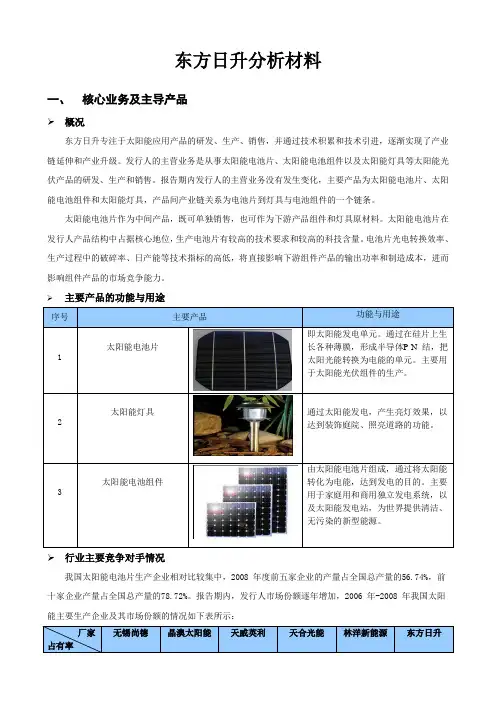
东方日升分析材料一、核心业务及主导产品概况东方日升专注于太阳能应用产品的研发、生产、销售,并通过技术积累和技术引进,逐渐实现了产业链延伸和产业升级。
发行人的主营业务是从事太阳能电池片、太阳能电池组件以及太阳能灯具等太阳能光伏产品的研发、生产和销售。
报告期内发行人的主营业务没有发生变化,主要产品为太阳能电池片、太阳能电池组件和太阳能灯具,产品间产业链关系为电池片到灯具与电池组件的一个链条。
太阳能电池片作为中间产品,既可单独销售,也可作为下游产品组件和灯具原材料。
太阳能电池片在发行人产品结构中占据核心地位,生产电池片有较高的技术要求和较高的科技含量。
电池片光电转换效率、生产过程中的破碎率、日产能等技术指标的高低,将直接影响下游组件产品的输出功率和制造成本,进而影响组件产品的市场竞争能力。
主要产品的功能与用途行业主要竞争对手情况我国太阳能电池片生产企业相对比较集中,2008 年度前五家企业的产量占全国总产量的56.74%,前十家企业产量占全国总产量的78.72%。
报告期内,发行人市场份额逐年增加,2006 年-2008 年我国太阳能主要生产企业及其市场份额的情况如下表所示:主要产品及工艺流程图二、主要市场概况截至2009 年12 月31 日,发行人主要用自产电池片生产组件;用生产电池片、组件过程中产生的低效片、破碎片作为生产灯具材料的主要来源;电池片销售收入主要由于发行人根据市场上交易性机会进行部分电池片的销售。
上述三种产品的收入合计占主营业务收入的比重达100%,具体明细如下表:三、主要竞争优势工艺技术改造优势东方日升非常重视对技术研发的投入和自主创新能力的提高,通过引进人才,联合高校和科研院所等方式形成了专业稳定的科研队伍。
近年来,发行人通过不断地技术攻关,形成了多项专利技术。
2007 年发行人与中国电子科技集团公司第四十八研究所联合实施的湖南省科技厅“等离子体增强化学气相淀积设备”、“太阳能电池制备用大口径闭管扩散设备”、“太阳能电池制备关键技术与设备研发”等重大科技专项研究,大大提高了设备和工艺制造的整体技术含量,主要性能指标达到国内领先、国际先进水平。
本文部分内容来自网络整理,本司不为其真实性负责,如有异议或侵权请及时联系,本司将立即删除!== 本文为word格式,下载后可方便编辑和修改! ==光伏作业指导书篇一:光伏电站土建和安装工作作业指导书光伏电站土建和安装工作作业指导书编制:审核:批准:1、概述 .................................................................. ..................................................................... (1)1.1 编制依据 .................................................................. (1)1.2 工程概况 .................................................................. (1)1.3 施工条件 .................................................................. (3)1.4 地质条件 .................................................................. (3)1.5 气象、水文条件 .................................................................. (4)1.6 施工特点、难点及对策 .................................................................. (5)1.7 工期目标 .................................................................. (5)1.8 工程质量目标 .................................................................. . (5)1.9 安全文明施工目标 .................................................................. .. (6)1.10 环境保护目标 .................................................................. .. (6)2、总体施工组织布置及规划 .................................................................. (6)2.1 施工总平面图 .................................................................. . (6)3、土建工程主要施工技术方案 .................................................................. (39)3.1 工程测量 .................................................................. . (39)3.2土方开挖工程施工 .................................................................. . (42)3.3电池组串支架基础钢筋工程 .................................................................. (43)3.4电池组串支架基础模板、砼工程及回填 .................................................................. .. (44)3.5综合楼、门卫室、水泵房等模板工程 .................................................................. (45)3.6综合楼、门卫室、水泵房等钢筋工程 .................................................................. (52)3.7综合楼、门卫室、水泵房等混凝土工程 .................................................................. .. (54)3.8墙体工程 .................................................................. .. (57)3.9给排水系统 .................................................................. . (65)3.9.1、给水工程 .................................................................. .. (65)3.9.1、排水工程 .................................................................. .. (70)3.10消防系统 .................................................................. (74)3.10.1消防系统设备 .................................................................. . (74)3.10.2准备工作 .................................................................. (74)3.11主要建筑物装饰工程施工 .................................................................. .. (75)4、施工总进度及措施 .................................................................. (9)4.1 进度合理性及主要节点工期 .................................................................. . (9)4.2 工期保证措施 .................................................................. .. (12)4.3 资源配置 .................................................................. . (15)5、确保工程质量的技术组织措施 .................................................................. .. (17)5.1质量方针 .................................................................. .. (17)5.2质量目标 .................................................................. .. (18)5.3质量保证体系 .................................................................. (18)5.4质量保证措施 .................................................................. (19)5.5施工“质量通病”防范、处理、控制的详细措施 ..................................................................226、确保安全生产的技术组织措施 .................................................................. .. (27)6.1安全目标 .................................................................. .. (27)6.1安全保证的组织机构 .................................................................. (27)6.2安全保证体系 .................................................................. (28)6.3保证安全的措施 .................................................................. .. (28)7、确保文明施工和环境保护的技术组织措施 .................................................................. (31)7.1文明施工 .................................................................. .. (31)7.2环境保护措施 .................................................................. (34)支架、光伏组件及汇流箱安装作业指导书 .................................................................. . (78)一、总说明及流程图 .................................................................. (80)1.1应遵循的规范 .................................................................. (80)1.2工程概况: ................................................................ (80)二支架安装 .................................................................. ..................................................................... . (85)2.1支架施工工器具 .................................................................. .. (85)2.2支架验收检查 .................................................................. (85)2.3支架安装 .................................................................. .. (85)三、光伏组件安装 .................................................................. . (90)3.1组件安装前应作如下准备工作:................................................................. (91)3.2光伏组件安装 .................................................................. (92)3.3.安全预防措施 .................................................................. (94)四、汇流箱安装 .................................................................. .. (95)4.1交底内容: ................................................................ ............................................................ 95 逆变器及升压变压器安装作业指导书 .................................................................. .. (106)一、编制依据 .................................................................. . (109)二.工程概括 .................................................................. . (109)三.作业人员资格及要求 .................................................................. .. (111)四.主要施工机械及施工所需工、器具 .................................................................. .. (112)五.施工准备 .................................................................. . (113)六、施工要求 .................................................................. . (114)七、作业方法、工艺要求及质量标准 .................................................................. (114)八、安全文明施工措施 .................................................................. (119)九、强制性条文 .................................................................. (122)电缆敷设施工作业指导书 .................................................................. . (126)据 .................................................................. (128)2、施工内容、工期及劳动力 .................................................................. .. (128)3、安装前的准备工作 .................................................................. .. (129)4、施工 .................................................................. ..................................................................... .. (130)5、技术措施 .................................................................. (131)6、质量要求 .................................................................. (145)7、安全注意事项 .................................................................. ............................................................. 152 接地施工作业指导书 .................................................................. (155)1.施工范围: ................................................................ . (156)2.编制依据 .................................................................. (156)备 .................................................................. (156)4.施工工序 .................................................................. (156)5.控制点 .................................................................. ..................................................................... . (161)6.工艺质量标准及验收级别。
PV Module Installation InstructionsLianyungang Shenzhou New Energy Co.,Ltd1 preface IntroductionThanks for purchasing PV modules of Lianyungang Shenzhou New energy Co., Ltd. . This manual refers to PV modules manufactured or sold by our company.This manual contains the information of installation and safe handling of Shenzhou’s PV modules (hereafter is referred to as "module”).All instructions shall be carefully read before installation. Please contact our sales department for further information if have any question.The installer shall be familiar with the mechanical and electrical requirement of PV system. The installer shall comply with safety precautions listed in this manual and local law regulations when installing the modules.Our company does not take the responsibility for the loss, damage, or expense arising that caused by any violation of this manual.This manual shall be properly kept for future reference (care and maintenance) and in case of sale or disposal of the module at the end of its useful life.Our company reserves the right of final interpretation of this installation manual.2 Warnings2.1 It requires specialized skills and knowledge for installation of solar photovoltaic systems. It shall be performed by qualified licensed professional installation personnel.2.2 When the modules are exposed to sunlight or other light sources, there is DC current generated in the modules, and the electrical part of the modules may be exposed to electric shock hazard.2.3 Apply modules to such as ground, roofs etc. outdoor environment. If the modules are installed on the roof, they must be installed on the roof with a certain fire protection capability. Consult the local construction department to decide which roof material to use. Appropriate rack structure shall be designed by system designer or installer.2.4 Do not disconnect the cables of modules when modules are on operation.2.5 Do not disassemble modules or move nameplate or any adhesion parts of modules.2.6 Do not place the modules where it is easy to produce or gather combustible gases.2.7 Artificially concentrated sunlight shall not be directed on the module.2.8 Any dropping or covering on modules is not allowed. Do not tread, stand or walk on modules.2.9 Do not pull or drag the modules by cables or connectors.2.10 Keep children away from modules during transportation and installation.2.11 Do not touch live terminals with bare hands. Use insulated tools for electrical connections. 2.12 Do not wear metal rings, bracelet, earrings, nose rings, lip rings or other metal accessories during transportation and installation. After the modules are shipped to the installation site, all packages should be carefully unpacked.2.13 Do not drill on the glass surface of module which will void its warranty. Do not damage the seal on the edge of the modules, otherwise the modules will fail. Damaged modules are dangerous (electric shock and fire). Such modules can not be repaired or repaired and should be replaced immediately.2.14 In order to reduce the risk of electric shock or combustion, it is possible to cover the surface of the modules with opaque material when installing modules.2.15 Make sure the connection between the rack and PV module is firmly and without loosen.2.16 All modules systems must be grounded. If there is no special requirement, please comply with the International Electrical Standards or other international standards.2.17 Do not wipe modules with corrosive chemicals.2.18 It may affect fire resistance of the house if roof-mounted; fire rating of the modules is rated as Class C according to IEC61730-2:2007, which shall be installed on the roof fire-rated above Class C.The system fire rating should always be evaluated along with the roof cover and mounting system. The fire rating of this module is valid only when mounted in the manner specified in the mechanical mounting instructions.3 Product Identification3.1 Each module has a label on the back containing following information:Product type, weight, size, fuse current, the system max voltage, rated power measured under standard test conditions, rated current, rated voltage, open circuit voltage, short circuit current. 3.2 Bar code (serial number): each module is registered with a unique serial number. It is permanently fixed in the module, which can be seen in front of module.3.2.1 The bar code (serial number) of the module is unique, and consists of 14 bits and a line. The first eight digits of serial number are composed of two manufacture codes, three date codes and three order serial Numbers. The line is followed by six numbers of component production. The number of components each order will not exceed 999999.Ltd.4 Installation4.1 Tools & Materials4.1.1 Screwdriver4.1.2 Wrench4.1.3 Mounting bracket4.1.4 Stainless steel screws, nuts, washers, clips and other accessories4.2 Installation Safety4.2.1 Wear protective headgear, insulating gloves and rubber shoes when modules are installed.4.2.2 During installation, avoid unnecessary touching of modules. The surface and frame of modules may be very hot, and there may be burns or electric shocks.4.2.3 Do not install in rainy, snowy or windy weather.4.2.4 Due to the danger of electric shock, if the junction box connecters are wet, please do not install it.4.2.5 When installing, do not throw anything, including modules and installation tools.4.2.6 Correct connection junction box, check wiring status, all wiring must not be separated from the modules, and take certain ways to make the wiring will not scratch or extrude the back glass of the modules.4.2.7 Whether or not the module is connected to the photovoltaic system, during installation or when there is light on the module, please do not connect the junction box or connectors.4.2.8 Do not overweight luggage or objects on the surface of modules, or distort the frame of modules.4.2.9 It is forbidden to place heavy objects on the glass of modules or to impact them, which may damage or cause cracks in the solar cells.4.2.10 It is forbidden to use sharp tools to scrub the glass of the modules, which will leave scratches on the modules.5 System designPlease use the equipment, connectors, wires and rack which match with solar power system. In a particular system, be sure to apply the same type of modules. Please refer to the short-circuit current (Isc) and open circuit voltage (Voc) showing on modules’ label as proper value to install and design when determining settling parameters such as rated voltage, the wire capacity, fuse, the controller capacity and module output power of relevant parts of PV system.In normal outdoor conditions, the generated current and voltage maybe different from the parameters listed in Table. Parameter table is measured under standard test conditions (STC), so concerning settling parameters of other parts of photovoltaic power generation system, such as rated voltage, the wire capacity, fuse, the controller capacity and module power output, it shall refer to the short-circuit current (Isc) and open circuit voltage (Voc) noted on modules’ label, with the redundancy value of 125% for design and installation.Make sure the array of modules installed within the Maximum permitted system voltage and the rating current and voltage of the sub-equipment such as regulators and inverters.The connection of modules: in accordance with system design, requirements of output voltage and current, modules can be series or parallel connected by their connecting wires; the maximum number of modules in series (N) is equal to the maximum system voltage Vmax divided by the open circuit voltage Voc of one single module; the number of modules in parallel is related to the selection of electrical equipment (inverters, controllers) under standard test conditions.Max System voltage≥N*Voc*[1+TCvoc*Tc(voc)* (Tmin-25)];N No modules in series;Voc Open circuit voltage of each module(refer to product label or data sheet);Tc(voc) Thermal coefficient of open circuit voltage for the module(refer to data sheet);Tmin The lowest ambient temperature.5.1 Location Selection5.1.1 The module should be installed at an ambient temperature of –40 °C to +40 °C. The module’s limit working ambient temperature range is from –40 °C to +85 °C.5.1.2 The maximum altitude for HT PV module is 2000m.5.1.3 Under standard test conditions (1000W / m² irradiance, AM 1.5 spectrum, 25 ° C (77 ° F) ambient temperature), the electrical performance parameters of modules, such as Isc, Voc, and Pmax. Tolerance of rating Pmax is±3%, Voc and Isc is±5%.5.1.4 A suitable installation location shall be carefully selected for modules.5.1.5 In the northern hemisphere, modules had better be installed facing south direction; in the southern hemisphere, modules had better be installed facing north.5.1.6 The tilt angle of the PV module is measured between the surface of the PV module and a horizontal ground surface (as shows in Figure 1). The PV module generates maximum output power when it faces the sun vertical. If you want the specific information of best install tilt angle, please consult the local authoritative solar system construction company.Figure 1 PV module tilt angle5.1.7 Modules shall be installed in the position of full sun exposure and not be obscured at any time.5.1.8 Generally, it is not recommended to be installed within 500 meters from the sea. The modules, as a general rule, can guarantee 25 years of useful life when it is installed in where 3 km away from the sea; if the installation site change to a place on a scale of 500m to 3000m from the sea, the modules need to increase the special protection (such as thickening the thickness of the oxide film of Aluminum metal alloy frame and the installation position must be processed with anti-corrosion treatment).5.1.9 When the battery is used in the photovoltaic system, the battery must be installed correctly so as to protect the safe operation of the photovoltaic system. Battery installation, use and maintenance shall be carried out in accordance with battery manufacturer's instructions.5.2 Choosing the appropriate inverterIt need take the output power, open-circuit voltage, short-circuit current of PV modules array into consideration when choose inverter type. And the minimum voltage of the module array should be higher than the threshold voltage of inverters to guarantee the inverters proper functioning.5.3 Choose the appropriate rackThe load calculation should be charged by system designers and installers to make sure all modules could bear predetermined load conditions. The choosing rack should pass all the inspection and test by third party test institution which possessing static mechanics analysis ability.6 Modules Installation6.1 Modules unpacking6.1.1 When the modules are shipped to installation place, do not unpack modules in humid and rainy weather.6.1.2 After being unpacked, the modules shall be placed horizontally; the tilt, heap pressure, leaning stack way are prohibited.Figure 2 Modules stack illustration6.1.3 Distance shall be kept between two batches of modules, no more than 23pcs modules shall be piled up together (it is recommended that no more than 23pcs modules whose weight is less than 27kg shall be piled up, and no more than 18pcs modules whose weight is no less than 27kg shall be piled up).6.1.4 Unpacking the package should refer to the following instructions as Figure 3, Any rude operation or use crowbar unclench into the boxes are prohibited. Pay attention to personal safety and modules safety when using tools.6.1.5 After unloading, the packing box shall be placed on dry and flat ground, and shall not be placed on wet, muddy and uneven ground;6.1.6 After the modules are transported to the construction site, the upper and lower boxes shall be separated and placed separately, and the two boxes of modules shall not be stacked; if the modules cannot be installed in time, attention shall be paid to the protection of modules and packing boxes to prevent the damage of natural disasters such as rain, snow, hail, typhoon, etc.Unpacking paper boxes process2. remove packaging side (shaded part).1. d dismantling the packing belt of thecoaming, the red tape is not dismantled.4. disassembly modules from side.3. r dismantling the packing belt of themodules.Figure 3 Upacking process6.2 Mounting with ClampsWe have tested its modules with a number of clamps from different manufacturers and recommends the use of clamps which have an EPDM or similar insulating washer, fixing use M8. The clamp must overlap the module frame by at least 0.28 in but no more than 0.39 in. All the installation methods described here are for reference only. We are not responsible for the design and installation of relevant modules and photovoltaic systems. Mechanical load and safety of components must be performed by a professional system installer or someone with relevant qualifications.• Use at minimum 4 clamps to fix modules on the mounting rails.• Modules clamps should not come into contact with the front glass and must not deform the frame.• Be sure to avoid shadowing effects from the module clamps.• The module frame is not to be modified under any circumstances.• When choosing this type of clamp-mounting method, use at least four clamps on each module, two clamps should be attached on each long sides of the module (for portrait orientation) and each short sides of the module (for landscape orientation). Depending on local wind and snow loads, additional clamps may be required to ensure that modules can bear the load.• Applied torque should refer to mechanical design standard according to the bolt customer is using, e.g:M8 ---- 16-20 N·m.mounting with clamps at longside of module- Load≤3600Pa(Using 4 clamps)NO. L*W(mm) 1 1324*992 2 1640*826 3 1640*992 4 1650*992 5 1665*992 6 1665*1002 7 1684*1002 8 1775*1052 9 1956*992 101979*1002 11 1987*992 12 2008*1002 132115*1052Notes: L is the length of PV module, W is the wide of module ,and the black shaded part is the installation range.mounting with clamps at shortside of module- Load≤2400Pa(Using 4 clamps)NO . L*W(mm) 1 1324*992 2 1640*826 3 1640*992 4 1650*992 5 1665*992 61665*1002 7 1684*1002 8 1775*1052 9 1956*992 101979*100212 2008*100213 2115*1052 Notes: L is the length of PV module, W is the wide of module ,and the black shaded part is the installation range.mounting with clamps at both long side & short side of module- Load≤2400Pa(Using 4 clamps)NO. L*W(mm)1 1324*9922 1640*8263 1640*9924 1650*9925 1665*9926 1665*10027 1684*10028 1775*10529 1956*99210 1979*100211 1987*992 Notes: L is the length of PV module, W is the wide of module ,and the black shaded part is the installation range.5400Pa≤Load≤8100Pa(Using 6 clamps)NO. L*W(mm)1 1324*9922 1640*8263 1640*9925 1665*9926 1665*10027 1684*10028 1775*10529 1956*992 101979*1002 11 1987*992 12 2008*1002 132115*1052Notes: L is the length of PV module, W is the wide of module ,and the black shaded part is the installation range.End Clamp installation(35/40mm optional)Middle Clamp installationPV module installed with clamp fitting method.6.3 Mounting with BoltsThe frame of each module has 14 x 9mm mounting holes, ideally placed to optimize the load handling capability, to secure the modules to supporting structure.• To maximize mounting longevity, our Solar strongly recommends using corrosion proof (stainless steel) fixings.• Secure the module in each fixing location with an M8 bolt and a flat washer, spring washer and nut as shown in Figure 4 and tighten to a torque of 16-20 N·m.Figure 4. SPV module installed with Bolt fitting method 1 Aluminum Frame 2 M8 Stainless bolt3 Flat Stainless Washer4 Spring Stainless Washer5 HEX Stainless NutMounting with BoltsNO. L*W(mm)Load≤2400Pa Load≤5400Pa Using 4 installation holeswith S or P holesUsing 4 installation holeswith S holes1 1324*9922 1640*8263 1640*9924 1650*9925 1665*9926 1665*10027 1684*10028 1775*10529 1956*99210 1979*100211 1987*99212 2008*100213 2115*10527 Electrical connection7.1 Please read the electrical wiring drawings carefully before wiring, when the modules followed the IEC standard, the maximum system voltage is 1500V DC.7.2 The connection of module and junction box: the module is connected with junction box by a dc cable. The cross-sectional area of cable and the connector capacity must be satisfied the system's short circuit current (the cable's cross-sectional area for a single module is recommended to be 4mm2, The outer diameter of the cable could be selected 5-7mm. The fuse current and the rated current of the connector should be higher than 15A.) Otherwise, the cables and connectors will overheat due to high current. Please note that the highest temperature of cable is 90 ℃, and the highest temperature of connector is 125 ℃.7.3 Aluminum frame and brackets of modules must be grounded with four ground holes of each module, which is marked on frames (it is recommended that each series/parallel of modules should be grounded once). The specific location of the grounding holes can be seen as the figure below. The ground wire and frame will be reliable grounding through the reserve grounding holes, by the installation bolts M5X10 ~ 15 matching plain washers, spring washers and nuts. Modules and ground cables shall be connected perfectly by wiring nose. Negative grounded inverters can be installed to prevent PID phenomenon.7.4 Where common grounding hardware (nuts, bolts, star washers, spilt-ring lock washers, flat washers and the like) is used to attach a listed grounding/bonding device, the attachment must be made in conformance with the grounding device manufacturer's instructions.7.5 Common hardware items such as nuts, bolts, star washers, lock washers and the like have notbeen evaluated for electrical conductivity or for use as grounding devices and should be used onlyfor maintaining mechanical connections and holding electrical grounding devices in the proper position for electrical conductivity. Such devices, where supplied with the module and evaluated through the requirements in UL 1703, may be used for grounding connections in accordance with the instructions provided with the module.7.6 The electrical connection shall conform to local electrical laws and regulations, "Y" type electrical connection mode is not allowed in module system electrical connection.7.7 Modules are equipped with bypass diodes(rated voltage 45V, rated current 20A); improper installation may damage diodes, cables or wiring box.7.8 Please wrap the connectors after taking out the modules without immediate installation so as to prevent damage caused by wind or rain. Use of lubricant for connectors is prohibited, because it leads fracture of connectors.7.9 Do not remove the waterproof rubber rings out of the junction box or connectors.7.10 Use of diesel oil for heating is strictly prohibited at installation site, which may lead to connector failure because the gas after combustion of diesel and other petroleum products.8 Maintenance8.1Modules need to be inspected and maintained regularly, check all electrical connections to ensure that there is no open circuit and well connected.8.1.1 Check the open circuit voltage of each module:8.1.2 Covered the modules completely by non-transparent material.8.1.3 Disconnect the wire terminals8.1.4 Remove the non-transparent material off the modules; check and measure the terminal open circuit voltage.8.1.5 If the measured voltage is reduced by 1/4, it supposed to be bypass diode damaged. Please test the bypass diode performance.8.2 It’s recommend that adopt the following maintenance to ensure the modules maintain the best performance:8.2.1 Check whether the modules have appearance defects: whether the surface of the modules are damaged or abnormal, whether the modules are occluded by objects, whether the fixing between the modules and the frame is loose or not, and contact qualified or experienced maintenance personnel to adjust or repair after finding the abnormalities.8.2.2 Clean modules once a year as much as possible, depending on local conditions. When dirt appears on the surface of modules, it will reduce the power generation. When cleaning, a soft sponge or a rag can be used to wet the glass surface of the modules. A mild, non-abrasive detergent can be used to remove fouling. The use of corrosive chemical cleaners is strictly prohibited. In order to reduce electric shock or burns, it is recommended to clean modules in the morning or evening.8.2.3 Mechanical and electrical checks are required every six months to ensure the modules’ connectors clean and reliable connected.And ensure good electrical connection and no corrosion.8.2.4 It need ask qualified person to check the modules if have any doubt on the modules.8.2.5 Please note that all maintenance instructions, such as brackets, charging rectifier, invertersand batteries, shall be complied.9 Meaning of crossed –out wheeled dustbin:Do not dispose of electrical appliances as unsorted municipal waste, use separate collection facilities.Contact your local government for information regarding the collection systems available.If electrical appliances are disposed of in landfills or dumps, hazardous substances can leak into the groundwater and get into the food chain, damaging your health and well-being.When replacing old appliances with new ones, the retailer is legally obligated to take back your old appliance for disposals at least free of charge.10 Disclaimer of LiabilityBecause the use of the manual and the conditions or methods of installation, operation, use and maintenance of photovoltaic (PV) product are beyond the control of Lianyungang Shenzhou New Energy Co.,Ltd. We do not accept responsibility and expressly disclaims liability for loss, damage, or expense arising out of or in any way connected with such installation, operation, use or maintenance.No responsibility is assumed by Lianyungang Shenzhou New Energy Co.,Ltd. for any infringement of patents or other rights of third parties, which may result from use of the PV product. NO license is granted by implication or otherwise under any patent or patent rights.The information in this manual is based on our knowledge and experience and is believed to be reliable, but such information including product specification (without limitations) and suggestions do not constitute a warranty, expresses or implied. We reserve the right to change the manual, the PV produce, the specifications, or product information sheets without prior notice。
3GW以上,携中环M12大硅片的东方日升组件明年下半年量产东方日升(300118.SZ)今天在浙江宁波正式宣布,与中环股份(002129.SZ)旗下的环欧国际,在基于良好信任,处于双方长远发展战略考虑,就单晶M12硅片等事宜进行深度合作。
东方日升副总裁黄强博士与环欧国际总经理张海鹏出席了210组件战略合作协议签约仪式。
这一举动,是外界首次看到有组件厂商宣布与中环股份M12大硅片加强合作的重大信息。
东方日升称,采用M12单晶硅片的500瓦高效组件具有优异的成本优势,具体表现为单线产能提升30%,度电成本(LCOE)下降6%,BOS成本降低9.6%等。
能源一号独家获悉,此次东方日升与中环合作的高效组件,将在明年第三季度实现量产,总规模或在3GW以上。
东方日升透露,致力于低成本高效化的产品研发,此次与环欧国际达成M12硅片合作,为公司在2020年的高效组件生产提供了强有力的支持。
东方日升将会把M12硅片与其他工艺结合,力争研发及大规模生产符合市场行情的高效产品,为客户带来实际的经济效益,符合公司的发展需要和长远规划。
中环股份作为全球领先的光伏硅片制造商,其推出的“夸父”M12大硅片,实现产业链更高转换效率,更高生产效率,更智慧的生产方式,面积比M2硅片增大了80.5%,应用最新产品后,6×10半片组件主流功率可以达到600W,如果叠加N型技术,组件功率可以提升到625W。
也就是说,M12的推出让光伏组件跳过5.0时代,直接步入6.0时代。
此次东方日升发布的500W高效组件,50半片版型,组件尺寸2205*1123*40mm,组件效率达20.2%。
对于行业内关注的中环股份M12硅片制造及下游匹配等方面,能源一号发现,该项目的前期制造设备已在进场中。
中环股份的大硅片项目位于内蒙古呼和浩特,实施该项目的公司名称为内蒙古中环协鑫光伏材料有限公司(下称“中环协鑫”)。
7月18日上午,中环协鑫的可再生能源太阳能电池用单晶硅材料产业化工程(五期项目)上梁仪式举行。