外文翻译--一个控制器使门式起重机和减摇桥精确定位
- 格式:doc
- 大小:374.00 KB
- 文档页数:23
[强力推荐]翻译优秀译文中英对照一种消除震动对增量式光学编码器测量影响的方法Method for eliminating influence of vibration over measurement of incremental optical encoder本发明旨在提供一种消除震动对增量式光学编码器测量影响的方法,以解决现有技术中增量式光学编码器抗震能力差的技术问题。
该方法是在现有增量式光学编码器的基础上,将光学编码器的光电读头数量增加为四个,并将四个光电读头沿指示圆光栅盘圆周均匀安置,使各读头相对于圆心成90度分布。
通过四个读头和AD转换电路及检相算法将四读头位置处的叠栅条纹相位解算出来,再以该四个特定位置的相位信息为基础,计算出标尺圆光栅盘震动方向和震动幅度,从而求出该震动产生的误差项并反代入光学编码器转动引起的叠栅条纹相位变化表达式,消除震动的影响。
本发明极大地降低了震动时光学编码器的检相误差,提高了存在震动时光学编码器的测量精度。
The invention aims to provide a method for eliminating the influence of vibration over the measurement of an incremental optical encoder, so as to solve the technical problem of poor anti-vibration ability of the incremental optical encoder in the prior art. The method is characterized in that on the basis of the existing incremental optical encoder, the number of photoelectric read heads of the optical encoder is increased to four; the four photoelectric read heads are evenly settled along the circumference of an indicating circular grating disc; and each read head is distributed at an angle of 90 DEG relative to a circle center. Stacked grating fringe phases in the positions of the four read heads are solved through the four read heads, an analog-digital (AD) conversion circuit and a phase detection algorithm; then the vibration direction and the vibration amplitude of a scale circular grating disc are calculated on the basis of the phase information of the four specific positions, so as to determine error terms produced during the vibration; and the vibration direction and the vibration amplitude are inversely substituted into an expression of stacked grating fringe phase changes caused by the rotation of the optical encoder, so as to eliminate the influence of the vibration. By adopting the method, phase detection errors of the optical encoder are greatly reduced during the vibration, and the measurement accuracy of the optical encoder is improved when the vibration exists.流感疫苗中的过敏原卵类粘蛋白或卵运铁蛋白定量检测Method for detecting allergen ovomucoid or ovotransferrin in influenza vaccine quantificationally本发明公开了一种流感疫苗中的过敏原卵类粘蛋白或卵运铁蛋白定量检测方法,在制备抗卵类粘蛋白或抗卵运铁蛋白单克隆抗体的基础上,经过配对抗体的筛选,建立的双抗体夹心酶联免疫吸附试验,来定量检测流感疫苗中卵类粘蛋白和卵运铁蛋白。
European Journal of Scientific ResearchISSN 1450-216X Vol.33 No.4 (2009>, pp.630-641© EuroJournals Publishing, Inc. 2009对龙门起重机系统抑制摇摆的最优跟踪控制M.A. AhmadControl and Instrumentation Research Group (COINS>,Faculty of Electrical and Electronics EngineeringUniversiti Malaysia Pahang, Lebuhraya Tun Razak26300, Kuantan, Pahang, MalaysiaE-mail:Tel: +609-5492366。
Fax: +609-5492377R.M.T. Raja IsmailControl and Instrumentation Research Group (COINS>Faculty of Electrical and Electronics EngineeringUniversiti Malaysia Pahang, Lebuhraya Tun Razak26300, Kuantan, Pahang, MalaysiaE-mail:Tel: +609-5492366。
Fax: +609-5492377M.S. RamliControl and Instrumentation Research Group (COINS>Faculty of Electrical and Electronics EngineeringUniversiti Malaysia Pahang, Lebuhraya Tun Razak26300, Kuantan, Pahang, MalaysiaE-mail:Tel: +609-5492366。
工程起重机中英文翻译对照To gain a certificate of competency for a cabin controlled bridge or gantry crane you must pass anassessment for a Bridge and gantry crane certificate conducted by an assessor registered by the Workcover Authority.Before taking the assessment you must obtain a log book and learn the competencies required to pass theassessment. Applicants must be at least 18 years old to gain a certificate.It is illegal to operate a cabin controlled bridge or gantry crane without a Bridge and gantry cranecertificate or a log book (under the supervision of a certificated driver).A cabin controlled bridge or gantry crane driver must know:●how to safely operate a bridge or gantry crane●how to detect any mechanical faults●about slinging loads,sheaves and drums,rope terminations,anchors andattachmentsIt is the responsibility of the applicant to make sure that a bridge or gantry crane of the correct class isavailable for the assessment at their workplace or has permission to use a crane at another location.If you operate this type of crane and sling loads in connection with the operation of this type of crane you will require a Dogging certificate in addition to being competent in its operation. See A guide for dogging available from the WorkCover Authority.桥梁合格证书起重机和龙门起重机为了获得一个龙门式起重机的合格证书,你必须通过操作龙门起重机进行评估,然后由劳保局注册管理局评估而得到的证书。
模糊控制式桥式起重机文摘:介绍了基于模糊控制的设计的吊车。
而不是分析复杂非线性吊车系统,该方法使用简单但有效的方法来控制起重机。
有双模糊控制器这处理反馈信息,位置的架空起重机和摆动角的负荷,抑制摇摆和加快速度当起重机运输沉重的负荷。
这种方法简化了设计过程的起重机控制器;此外,双控制器方法减少了规则数当完成模糊系统。
最后,实验结果通过起重机模型证明了该方案的有效性。
关键词:桥式起重机;模糊控制1 介绍桥式吊车系统广泛应用于工业移动沉重的货物。
因此反摇摆和位置控制已成为需求作为核心技术自动化起重机系统,能够灵活的空间自动运输。
起重机控制的目的是减少的摆动负载移动时电车到所需的位置尽可能快的。
然而,高架起重机已经严重问题:起重机加速,需要运动,总是引起不良负荷摆动。
这样的摇摆的负载通常会降低工作效率,有时导致负载损害赔偿,甚至安全事故。
因此,需要更快货物装卸要求精确控制起重机的运动所以,它的动态性能得到了改进。
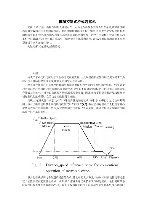
传统上,起重机操作员驱动小车与这些步骤的加速运动,匀速运动,减速运动,运动和断裂图1显示了距离速度参考曲线的传统桥式吊车的操作[4,5]。
有经验的起重机工人把电车精心保持负载从严重的摇摆。
然而,保守的控制方法在现代工业无效。
本研究提出了模糊双控制器来控制小车起重机。
很多的尝试解决这个问题的摇摆的负载。
他们中的大多数集中控制抑制负载摆动不考虑这个位置误差在起重机运动[6]。
此外,几个作者考虑优化技术来控制起重机。
他们利用最小时间控制技术减少负载摆动(7 ~ 9)。
因为负载的摆动取决于运动和加速度的小车,减少周期时间和减少负荷摆动部分相互冲突的需求。
除此之外,还有许多论文调查稳定性问题的控制器设计[10 ~ 12],但是这些研究缺乏实验说明了有效性。
本研究提出了一种实用的解决方案为反摇摆和精确位置控制的起重机。
这个职位的电车、旋角的负荷及其分化是应用于衍生出正确的控制输入的电车起重机。
两个模糊逻辑控制器(FLC)是用来交易单独与反馈信号,偏转角和电车位置和他们的负效应。
A controller enabling precise positioning and sway reduction inbridge and gantry cranesKhalid L. Sorensen, William Singhose, Stephen DickersonThe George W. Woodruff School of Mechanical Engineering, Georgia Institute of Technology, 813 Ferst Dr., MARC 257, Atlanta, GA 30332-0405, USAReceived 28 September 2005; accepted 30 March 2006Available online 5 June 2006一个控制器使门式起重机和减摇桥精确定位Khalid L. Sorensen, William Singhose, Stephen Dickerson, 乔治亚机械工程学院,乔治亚技术学院, Ferst博士813,MARC 257 ,亚特兰大,GA 30332-0405,美国,2005年9月28日收到,2006年3月30日接受,2006年6月5日可在线使用.一个控制器使门式起重机和减摇桥精确定位摘要起重机是很难精确操纵载荷的。
振荡,可以诱导成大桥或手推车的阻尼系统轻度运动,并且还对环境造成滋扰. 为解决上述两种振荡的来源,结合反馈和输入整形控制器的发展。
该控制器是由三个不同的模块组成,反馈模块的检测和定位误差补偿; 第二反馈模块侦测并拒绝振动; 使用塑料造填充的第三个模块,以减轻振荡。
一个使用精确的模型矢量驱动的交流感应马达,为典型的大型起重机, 用同一个褶分析技术,将非线性动力学起重机器分为对照设计。
在佐治亚技术学院实验10吨桥式起重机控制器。
该控制器具有良好的定位精度和性能以减少摆动.。
附录英文原文Crane Scheduling with Spatial ConstraintsAndrew Lim, Brian Rodrigues, Fei Xiao, and Yi ZhuAbstractIn this work, we examine port crane scheduling with spatial and separation constraints. Although common to most port operations, these constraints have not been previously studied. We assume that cranes cannot cross, there is a minimum distance between cranes and jobs cannot be done simultaneously. Theobjective is to find a crane-to-job matching which maximizes throughput under these constraints. We provide dynamic programming algorithms, a probabilistic tabu search and a squeaky wheel optimization heuristic for solution. Experiments show the heuristics perform well compared with optimal solutions obtained by CPLEX for small scale instances where a squeaky wheel optimization with local search approach gives good results within short times.1 IntroductionThe Port of Singapore Authority (PSA) is a large port operator located in Singapore, one of the busiest ports in the world. PSA handles 17.04 million TEU’s annually or nine percent of global container traffic in Singapore, the world’s largest transshipment hub. PSA is concerned with maximizing throughput at its port due to limited port size, high cargo transshipment volumes and limited physical facilities and equipment . Crane scheduling and work schedules are critical in port management since cranes are at the interface between land and water sections of any port, each with its own traffic lanes, intersections, and vehicle flow control systems. In this multi-channel interface we are likely to find bottlenecks where cranes and other cargo-handling equipment (forklifts, conveyors etc.) converge.Sabria and Daganzo studied port operations which focused on berthing and cargo-handling systems. In berthing, which is a widely-analyzed port activity, queuing theory has been used widely. Traffic and vehicle-flow scheduling o n land in ports has also been well studied. Danganzo studied a static crane scheduling case where cranes could move freely from hold to hold and only one crane is allowed to work on one hold at any one time.The objective was to minimize the aggregate cost of delay. In [13], container handling is modelled as ―work‖ which cranes perform at constant rates and cranes can interrupt work without loss of efficiency. This constituted an ―open shop‖ parallel and identical machines problem, where jobs consist of independent,single-stage and pre-emptable tasks. A branch- and-bound method was used to minimize delay costs for this problem. Crane scheduling has also been studied in the manufacturing environment context .Commonly-found constraints affecting crane operations are absent in studies available on the subject. Such constraints affect crane work scheduling and need to be factored into operational models. These include the basic requirement that operating cranes do not cross over each other. Also, a minimum separating distance between cranes is necessary since cranes require some spatial flexibility in performing jobs. Finally, there is a need for jobs arriving for stacking at yards to be separated in arrival time to avoid congestion.We found that operational decision-making at PSA was based largely on experience and simulation techniques. While the latter is of value, analytic models are an advantage and are not limited by experience-generated rules-of-thumbs or simulation. The object of this work is to address the need for such models which take into account common spatial and separation requirements in the scheduling cranes. This work augments Peterkofsky and Daganzo study .2 Problem DescriptionDuring the time ships are berthed, various cargo-handling equipment is used to unload cargo, mostly in the form of containers. Different types of cargo require different handling and many ports have bulk, container, dry and liquid-bulk terminals. Cargo that is containerized can be loaded and unloaded in a fewer number of moves by cranes operating directly over ship holds or by crane arms moving over holds or deck areas.Cargo stacked in yards is moved by cranes onto movers and transported for loading onto shi ps. ‖Cargo‖ here comprises containers of different capacities, which, whether in ships or in yards, are parcelled into fixed areas for access to cranes. For example, cargo placed in specific holds or deck sections on ships, or in sections within yards.Containers are unloaded from ships by quay cranes onto movers or trailers which carry them to assigned yard locations where they are loaded onto stacks by yard cranes. Containers destined for import are set aside, and restacking, if required, is carried out. In the movement of containers, sequencing is crucial because containers are stored in stacks in the ship and on the yard and lanes may be designated to specific trailers at certain times. In addition, the movement of containers involves routing and crane operations where timings may be uncertain. In fact, crane scheduling is one activity among many that determine the movement of containers. Other such activities includeberthing, yard storage, ship stowage and vehicle allocation and routing, all of which can be uncertain. Because of the uncertainty present over all activities, it is almost impossible to implement a plan over any length of time. This difficulty is present in scheduling cranes. For example, although a set of jobs may be assigned to a certain crane, it may not be possible for the crane to complete processing a job in this set onto movers once it was known that the route these movers are to take was congested. As another example, although we can specify that jobs bound for the same yard space are not unloaded from ships simultaneously, we cannot expect such containers to be unloaded at a time other than the allotted time interval, since a required resource to complete the job may become unavailable after this time, as for example, if the yard crane becomes unavailable. In view of the dynamically changing environment, a central control devises and maintains a job assignment plan that is periodically updated in order to coordinate operations, including crane scheduling. The system will allocate all jobs and resources periodically.In the port we studied, a job parcel can include a number of ships and a number of cranes together with jobs. Typically, there can be up to five ships with four to seven cranes per ship and a number of jobs depending on the size and configuration of ships. J obs have a profit value assigned to them and resources, e.g., cranes, movers, lanes etc., are assigned to each of the jobs depending on their value to the overall operations plan which aims to optimize total throughput. When an assignment plan is updated, the central system reassesses the current state of operations to regroup and reassign job parcels. Because of this, time is accommodated by constant adjustments of job parcels and assignments based on the current state of all operations. Hence, once jobs and resources are assigned for the time period no update is necessary.Jobs come in different sizes, and cranes have different handling capacities. Since we make the assumption that any crane assigned to a job completes it, the throughput or profit, for a given crane-to-job assignment, is a fixed value independent of other crane-to-job assignments.The problem is naturally represented by a bipartite graph matching problem when we take cranes and jobs to be the vertices and define the weights of connecting edges to be crane-to-job throughput. This representation is shown in Figure 1.Figure 1This matching problem is interesting because, in practice, a number of spatial constraints arise for cranes and jobs. We first introduce qualitative notions of three particularly common constraints which we call ―spatial‖ constraints since they are related to the relative posi tions of cranes and jobs. Our objective is to find a crane-to-job assignment scheme which maximizes throughput under these constraints. For reasons given above, we assume that crane-to-job assignments are performed in a given time interval, i.e., there is no temporal component in the problem. Detailed definitions will be given in the relevant sections of this paper.1. Non-crossing constraint: Cranes cannot cross over each other. This is a structural constraint on cranes and crane tracks.2. Neighborhood constraint: There is a minimum distance between cranes. This arises, for example, since cranes require flexibility in space to perform jobs and/or for safety reasons. The effect of this constraint is that neighboring jobs may be affected and may not be assignable to other cranes.3. Job-separation constraint: Certain jobs cannot be done simultaneously. For example, jobs bound for the same yard may require separation in time to avoid trailer congestion in lanes.In the following sections, we first consider these constraints separately and then simultaneously. In section 3, an O(mn) dynamic programming (DP) algorithm is given to solve the problem with only the Non-crossing constraint where m is the number of cranes and n is the number of jobs. In section 4, we use an O(m2n) dynamic programming algorithm to achieve an optimal solution for the problem with both the Non-crossing and Neighborhood constraints. In section 5, assuming all three spatial constraints, we show the problem to be NP-complete and give two heuristic approaches to solve the problem —a probabilistic tabu search and a squeaky wheel optimizationwith local search method. In section 6, we provide experimental results and compare the different approaches.3 Scheduling with the Non-Crossing Constraint3.1 The ProblemThroughout this work, C= {c1, c2, . . . , c m} is a set of cranes and J= {j1, j2, . . . , j n} a set of jobs. The order of subscripts assigned to the cranes and jobs represents their spatial (assumed linear) distribution, i.e., the neighbor of j1is j2, the neighbors of j2are j1and j3,. . . , and the neighbor of j n is j n−1, The same holds for the cranes.An m × n adjacency matrix, W , is used to represent the relationships between jobs and cranes. For each W x,y∈W , the value W x,y represents the throughput when job j y is assigned to crane c x where W x,y= 0 if job j y cannot be assigned to crane c x. The W x,y values arise from the different job sizes and crane capacities.We seek a solution set,R={(p, q )|1 ≤p≤ m, 1≤q≤n, W p,q> 0}, such that the following constraint is satisfied: For all (p1, q1), (p2, q2)∈R, p1< p2if and only if q1< q2. Viewing p’s and q’s, as subscripts in C and J respectively, we see that any crane-job assignment in R satisfies the Non-crossing Constraint.The objective is then to find a set R which maximizes ∑(p,q)∈rWp,q subject to the constraints that each job is assigned to at most one crane and each crane is assigned to at most one job.3.2 Algorithm DescriptionWe now provide a dynamic programming (DP) approach and describe how to characterize an optimal solution. DP procedures for computing values of solutions in a bottom-up way and for constructing solutions from computed information are omitted since they follow directly and are required only in implementation.3.2.1 The Structure and Value of an Optimal SolutionWe consider the cranes one by one. For each crane c x, we assign every job j y(1 ≤ y ≤ n) to it and compute the total throughput to derive a partial optimal solution P x,y which denotes the optimal value up to the step we assign job j y to crane c x. Here, it is not necessary that job j y is actually assigned to crane c x, i.e., (x, y) ∈R x,y may not hold, where R x,y is the partial solution set corresponding to the partial optimal solution P x,y.The following computes the partial optimal solution, P x,y, recursively, for the different cases:1. If x = 1 and y = 1, P1,1:= W1,12. If x = 1 and y > 1, P1,y:= max{W1,y’, P1,y-1}3. If x > 1 and y = 1, P x,1:= max{W x,1, P x-1,1 }4. If x > 1 and y > 1, P x,y:= max{P x,y-1,P x-1,y’ ,P x-1,y-1+W x,y}(1) is the basic case: If we only consider the first crane and the first job, we will assign this job to the crane if the job can be done by the crane. (2) and (3) are both special cases, i.e., when there is only one node in each part of the bipartite graph. As these are symmetrical, we need consider only (2). For crane c1and job j y, we have two choices: either, assign j y to c1, or, assign a job from {j1, . . . , j y−1}to c1. This is because at most one job can be assigned to this first crane. The throughput for the first choice is W1,y while the throughput for the second choice is P1,y−1 , which represents the maximum throughput if we assign a job among j1, j2, . . . , j y-1to crane c1. To achieve the cumulative optimal, we choose the larger of these. (4) is the general case in the DP algorithm. For c x and job j y(x > 1, y > 1), we have three choices:•Leave job j y unassigned . We are reduced to assigning cranes c1, c2, . . . , c x to jobs j1, j2, . . . , j y-1. By induction, the optimal value is then P x,y-1;•Leave crane c x unassigned . We are reduced to assigning cranes c1, c2, . . . , c x-1 to jobs j1, j2, . . . , j y. By induction, the optimal value is then P x-1,y;•Assign crane c x to job j y(or, leave both unassigned if they are not assignable to each other). In this case, the total throughput is the throughput from this assignment plus the throughput from assigning cranes c1, c2, . . . , c x-1 to jobs j1, j2, . . . , j y-1. Hence, the value is P x-1,y-1+W x,y.Taking the maximum of these throughput values, the optimal solution is then the final partial optimal solution P m,n obtained.3.2.2 A Proof of Optimal SubstructureWe provide an outline a proof that the problem defined in this section possesses optimal substructures necessary in using DP. An important property for P x,y is: P x,y≥P x’,y’,if x ≥ x’and y ≥ y’(*), which is easily verified since P x,y≥ P x,y-1 and P x,y≥ P x-1,y. We can now verify the four cases given above by induction:1. If x = 1 and y = 1, clearly P1,y = W x,1 is the only solution and must be optimal2. If (x, y)∈R’x,y, then P x,y’≤P ak-1,bk-1+W x,y. By (*), we know P x-1,y−1≥P ak-1,b-1since x − 1 ≥ ak-1, y-1 ≥ bk-1. So P x,y’≤ P x-1,y-1+W x,y. Because P x,y≥P x-1,y-1+ W x,y, we get P x,y≥ P x,y’ , which contradicts our assumption P x,y’> P x,y. Hence, P x,y is the optimal solution.We can conclude that P x,y is the optimal solution for all (x, y), 1 ≤ x ≤ m, 1 ≤ y ≤ n,3.3 The Time Complexity of the AlgorithmThe computation for every partial solution P x,y is in constant time, so the time complexity for this algorithm is O(mn).4 Scheduling with the Neighborhood Constraint4.1 The ProblemIn this problem, both the Non-crossing constraint and the Neighborhood constraint are considered. In addition to the Non-crossing constraint, we use the set S= {s1, s2, . . . , s m} to represent the Neighborhood constraint associated with the cranes. Here s x= k if crane c x performs job j y and job j z(a ≤ z ≤ b, z= y) cannot be worked on by any other crane, wh ere a = max{1, y − k}and b = min{y + k, m}. In other words, if crane c x performs job j y, the job ―interval‖ centered at y with length 2k + 1 is affected by crane c x when s x= k.We seek a solution set R = {(p, q)|1 ≤ p ≤ m, 1 ≤ q ≤ n, W p,q> 0} satisfying:1. For all (p1, q1), (p2, q2) ∈ R, p1< p2if and only if q1< q2(Non-crossing constraint)2. For all (p, q) ∈R, if 1 ≤ p’≤ m and p’= p, and a ≤ q’≤ b, where a = max{1, q − s p} and b = min{q + s p, n}, then (p’, q’) ∈R (Neighborhood constraint)Our objective is to find R that maximizes the total weight ∑(p,q)∈rWp,q where each job is assigned to at most one crane and each crane is assigned to at most one job.4.2 Algorithm DescriptionWe follow the approach in section 3.2 here.4.2.1 The Structure and Value of an Optimal SolutionWe continue to consider the cranes one by one. For each crane c x, we attempt to assign every job j y(1 ≤ y ≤ n) to it and compute the total throughput up to this step to give a partial optimal solution P x,y.Here, the partial optimal solution P x,y is cumulative and the edge inclusion (x, y) ∈R x,y may not hold. However, different from the definition used in the previous section, crane x must be assigned some job j (1 ≤ j ≤ y) for P x,y, i.e., there must be an edge (x, j) ∈R x,y, where (1 ≤ j≤ y); if there is no job in the interval [1, y] that can be assigned to crane x, then P x,y= 0. Now, we define the value of the partial optimal solution P x,y for the different cases:1. If x = 1 and y = 1, P1,1=W1,12. If x = 1 and y > 1, P1,y:= max{W1,y,P1,y-1}3. If x > 1 and y = 1, P x,1=W x,14. If x > 1 and y > 1, P x,y:= max{P x,y-1,P i,c+W x,y}, 1 ≤ i < x, c = y− max{s x, s i} − 1.(1) is the basic case and (2) and (3) are the special cases. (2) has been explained in the previous section. (3) is different. Since we require for P x,y that crane c x must be assigned job j y, we have no choice but to assign this job to the current crane when there is only job available. The induction step in (4) is somewhat complex. In the first case, we keep job j y unassigned, so we are reduced to assigning cranes c1, c2, . . . , c x to jobs j1, j2, . . . , j y; hence, we obtain P x,y-1. In the second case, since we assigned job j y to crane c x, the Neighborhood constraint for c x must be considered. Also, we must consider the Neighborhood constraint for the cranes c1, c2, . . . , c x which are assigned to jobs. The Non-crossing constraint simplifies the computation leaving us only to check the neighborhood constraint for the ―largest label‖crane assigned and is the reason the c value is needed in the formula.The final optimal is the maximum value of all partial optimal solutions obtained,i.e., it is max{P x,y} over all (x, y), 1 ≤ x ≤ m, 1 ≤ y ≤ n.4.2.2 A Proof of Optimal SubstructureSimilar to the earlier problem, we show that this problem has an optimal substructure. As before, we use the fact that P x,y≥ P x,y’ if y ≥ y’(**). This is easy to verify since a partial optimal solution is cumulative for each crane x. As before, we have the following cases:1. If x = 1 and y = 1, clearly P1,1= W1,1is the optimal solution2. If x = 1 and y > 1, only one crane is involved, so the Neighborhood constraint does not take the effect. The proof is then as given in the previous section3. If x > 1 and y = 1, since crane c x has to be assigned a job, and there is only one job, clearly P x,1 = W x,14. If x > 1 and y > 1, P x,y= max{P x,y-1, P i,c+ W x,y}, 1 ≤ i < x, c = y−max{s x, s i} − 1. We assume there is an optimal solution P x,y0> P x,y and the solution set corresponding to P x,y’is R’x,y={(c a1, j b1), (c a2,j b2), . . . , (c ak,j bk)}. Here, we can take this set to be ordered, i.e., a1≤ a2≤ . . . ≤ a k and b1≤ b2≤ . . . ≤ b k, by virtue of the Non-crossing constraint. Noting a k= x from the definition above, there are now two possibilities for P x,y’:(a) If (x, y) ∈R’x,y, then P x,y’≤ P ak,bk, since P ak,bk is the partial optimal solution. Hence, P x,y’≤ P x,bk, since a k= x. From property (**), we know P x,y-1≥ P x,bk since y − 1 ≥ b k(job j y is unassigned). So P x,y−1 ≥ P x,y’. By the recursive definition, P x,y≥ P x,y-1. Hence, we get P x,y≥ P x,y’, which contradicts the assumption P x,y’ > P x,y. So P x,y is the optimal solution in this case(b) If (x, y ) ∈ R’x,y, then P x,y’≤ P ak-1,bk-1+W x,y, since P ak-1,bk-1is the partial optimalsolution. Obviously 1 ≤ a k-1<x, so we let i = a k-1and c = y−max{s x, s i} − 1. We know bk−1≤c since the cranes c x andc i are both assigned jobs and their Neighborhood constraints are in effect. From (**), we get P i,c≥ P i,bk-1because of c ≥ b k−1, i.e., P ak-1,c + W x,y≥ P ak-1,bk-1,+W x,y, and so P ak-1,c+W x,y≥P x,y’. From the definition P x,y= max{P x,y-1,Pi,c+W x,y}, we know P x,y≥ P x,y’ , which contradicts the assumption P x,y’> Px,y. Hence, P x,y must be the optimal solution in this caseWe conclude that P x,y is the optimal solution for all (x, y), 1 ≤ x ≤ m, 1 ≤ y ≤ n.4.3 The Time Complexity of the AlgorithmSince, for each partial solution P x,y, we take the maximum value of the partial solutions P i,c, 1 ≤ i < x, the time complexity is O.5 Scheduling with the Job Separation Constraint5.1 The ProblemWe can now study the third and most general spatial constraint —the Job-separation constraint. An n × n matrix D represents this constraint: D p,q= 1(1 ≤ i ≤ n, 1 ≤ j≤ n), when job j p and j q cannot be done simultaneously. Otherwise, the elements of D are 0. Note that D is symmetric. We seek a solution set R = {(p, q)|1 ≤ p ≤ m, 1 ≤ q ≤ n, W p,q> 0}, for which the following three conditions are satisfied:1. For all (p1, q1), (p2, q2) ∈ R, p1< p2 if and only if q1< q2(Non-crossing constraint)2. For all (p, q) ∈R, if 1 ≤ p’≤ m and p’= p, and a ≤ q’≤ b, where a = max{1, q − s p} and b = max{q + s p, n}, then (p’, q’) ∈R (Neighborhood constraint)3. For all (p, q) ∈R, if 1≤p’≤ m, and D q,q’= 1, then (p’, q’)∈R(Job-separation constraint)The objective is to find a set R which maximizes total weight ∑(p,q)∈rWp,q where each job is assigned to at most one crane and each crane is assigned to at most one job.5.2 Proof of NP-completenessTo show that this problem is NP-complete, we use the Independent Set problem which is defined as follows: Given a graph G= (V, E) and a positive integer k≤ |V |, is there a V’⊆ V such that for all u, v ∈V’, the edge (u, v) is not in E and |V’| ≥ k?In order to prove that this problem is NP-hard, we transform an arbitrary instance of the Independent Set problem to the problem in polynomial time. Assuming there are n nodes in the graph G = (V, E) of the Independent Set problem, we construct the model with n cranes and n jobs where the only edges are (1, 1), (2, 2),..., (n, n), all with weight equal to 1. The Job-separation constraint matrix D is defined as follows: For all(x, y) ∈ E, D x,y= 1, otherwise D x,y= 0, 1 ≤ x, y ≤ n. The transformation is illustrated in Figure 5 and can be achieved in polynomial time.Now we show that the Independent Set problem has a solution of size k if and only if the problem has a solution with total profit k. First, if there are k independent nodes in graph G, there must be k jobs that do not, pairwise, conflict. Since we constructed n parallel edges with weight 1, the Non-crossing constraint and Neighborhood constraint do not have any effect here. Hence, we can use k cranes to do the k jobs without violating the Job-separation constr aint with total profit k. If we now assume that there is a solution in this problem with profit k, there must be k jobs selected without violating the Job-separation constraint. There must be k nodes that are not connected by any edges and therefore a set of nodes of size k.We can verify solutions by checking crane-job assignments one by one for violation of the three constraints. Clearly, this can be done in polynomial time, so the problem is in the class NP. Since the problem has been shown to be NP-hard, it is NP-complete and, unless P = NP, there are no polynomial algorithms to solve it optimally. It would be useful therefore to develop heuristic solutions for the problem, which we do in the following sections.5.3 A Probabilistic Tabu Search ApproachTabu Search (TS) is a search procedure that iterates from one solution to another by moves in a neighborhood space with the help of an adaptive memory. Probabilistic Tabu Search (PTS) is a variant of TS, which places emphasis on randomization when compared with basic TS . The basic approach is to create move evaluations that include references to the tabu status and other relevant biases from TS strategies using penalties, modifying underlying decision criterion and selecting the next move among those neighborhood moves with different probabilities which are based on different evaluation values . In this section, we describe how it can be employed for the crane scheduling problem.5.3.1 Neighborhood StructureFrom an initial feasible solution obtained by a greedy method or a random crane-job assign-ment, the graph representation becomes almost edge ―saturated‖, i.e. we can hardly add an edge without violating the Non-crossing, Neighborhood and Job-separation constraints. We can however delete an edge from the current solution and try to add other edges until it is ―saturated‖ again. Deleting the edge which connects crane c and job j allows some cranes and jobs to become assignable. Obviously, thesecan only come from cranes and jobs which are neighbors to c and j, respectively, which do not violate the Non-crossing constraint w.r.t. all current assignments (discounting the c to j assignment). Jobs selected must also satisfy the Neighborhood and Job-separation constraints. After deleting the edge connecting c to j, we consider each neighbor of c from these feasible neighbors together with c, one by one. For each crane, we assign a probability p1for it to be selected for a job. For each selected crane, we have two types of assignments: one is a greedy assignment which selects a compatible job with the largest weight; the other is a random assignment which randomly picks one job from all the compatible jobs. Which scheme is chosen depends on yet another probability, p2.5.3.2 Tabu Search MemoryTS memory structures guide the search process. There are two kinds of memory structures. One is ―short-term memory‖, which can prevent the search from being trapped in a local optimum and the other is ―long-term m emory‖, which provides diversification and inten-sification.Short-term memory restricts the composition of new solutions generated. If an edge is deleted in a move, we forbid its addition in the next few moves; similarly, if an edge is added in a move, we forbid its deletion in the next few moves. Such a mechanism prevents the search from revisiting local optima in the short term and reduces the chance of cycling in the long term.How long a restriction is in effect depends on a tabu tenure parameter, which i dentifies the number of iterations a particular restriction remains in force . We implemented short- term memory using a recency-based memory structure as follows.future iteration values that forbid a reversal of the moves on adding edge (x, y) or deleting edge (x, y). Furthermore, let tabu add tenure and tabu delete tenure be the values of tabu tenure for these two moves. When the TS restriction is imposed, we update the recency memory by:tabu add(x, y) = iter + tabu add tenuretabu delete(x, y) = iter + tabu delete tenureWe assign positive penalties to edges in tabu status, which means they are forbidden by the recency memory.A TS restriction is overridden by aspiration if the outcome of the move under consideration is sufficiently desirable. This can be achieved by deducting a large numberfrom the total penalty.5.3.3 Move EvaluationAfter finding all neighborhood candidate moves, we evaluate these moves so that they are ready for selection. The resulting evaluation value is in two parts: the total profit and the penalties. For our crane scheduling problem, the penalties comprise: (1) Short-term memory penalties which include tabu status penalties as well as aspiration satisfaction ―penalties‖ (2) Long-term memory penalties which include transition measure and residence measure penalties and (3) Penalties for other biases.5.3.4 Probabilistic Move SelectionAfter evaluating all candidate moves, we select one move to proceed. The fundamental idea of move selection is to choose the best move, i.e., choose the move with the highest evaluation. However, we found that this greedy selection strategy is strongly biased. We therefore made adjustments using probabilities. The strategy for a probabilistic move selection is given as follows:1. Generate the candidate list and evaluate candidate moves which have described above2. Select the move from the candidate list with the highest evaluation value3. Accept the move with probability p and exit; otherwise, go to (4). Here, p is a param-eter and is set to 0.3 in the algorithm4. Remove the move from the candidate list. If the list is empty, accept the first move ofthe original candidate list and exit. Otherwise, go to (2).It is easily shown that the probability of choosing one of the best k moves is 1 − (1 − p)k, which is large even if p is not large. For example, if p is 0.25, the probability of choosing the best 5 moves is 0.763, the best 10 moves is 0.944. We can therefore choose relatively high evaluation moves while avoiding favoring those with highest evaluations always.5.4 SWO with Local Search Approach―Squeaky Wheel‖ Optimization (SWO) is a general approach to optimization and consists of a Construct-Analyze-Prioritize cycle at its core. The Analyzer will assign a numerical ‖blame‖ value to the problem elements that contribute to shortcomin gs in the current solution. The Prioritizer will modify sequences of problem elements and。
中英文对照起重机术语大全起重机(crane)moblie crane 移动式起重机truck crane 汽车式起重机wheel crane / wheeled crane 轮胎起重机crawler crane / caterpillar crane 履带吊;履带式起重机tower crane 塔吊; 塔式起重机-construction tower cranes / building tower crane 建筑塔式起重机,建筑塔机-luffing jib tower crane 动臂塔式起重机-tower jib crane 塔式挺杆起重机(含义与上同)bridge crane/traveling crane/overhead crane 桥吊;桥式吊车; 桥式起重机-electric traveling crane 电动桥式起重机(俗称行车、天车)-electric double-beam bridge crane 电动双梁桥式起重机portal crane / portal bridge crane门式起重机- semi-goliath crane 半门式起重机- semi-portal bridge crane 半龙门起重机gantry cranes 龙门起重机- rubber tyred gantry crane 轮胎式龙门吊- electric gantry crane 电动龙门式起重机- hook gantry crane 吊钩龙门吊- economical gantry crane 简单龙门起重机; 简易龙门起重机- rubber tyred container gantry crane 轮胎式集装箱龙门起重机barges / floating Cranes 船式起重机; 浮吊; 浮式起重机水上起重机boom crane 吊杆起重机; 桁梁起重机; 臂式起重机; 伸臂起重机bucket crane 料罐起重机; 吊斗起重机building crane 建筑起重机cable crane 索道起重机; 缆索起重机container crane 集装箱起重机electric crane 电动吊车; 电动起重机; 电力起重机electriomagnet crane 电磁铁起重机electric jib crane 电动单臂起重机fixed crane 固定式起重机climbing crane 爬升式起重机;攀爬式起重机fixed derrick crane 固定式动臂起重机fixed jib crane 固定式悬臂起重机flying crane helicopter 起重直升机hoist crane 起重葫芦hoisting crane 升降起重机hook type crane 钩式起重机twin hood crane 双钩吊车mobile crane 移动式吊车; 移动式起重机quay crane 码头起重机; 码头桥式起重机; 港岸起重机revolving track crane 回转式轨道起重机circular crane 旋转式吊车环形吊车roof crane 屋顶起重机transporter crane 桁架式起重机electric crane 电动吊车; 电动起重机gasoline crane 汽油起重机hydraulic crane 液力起重机; 液压起重机derrick crane 人字扒杆人字起重机-travelling derrick crane 移动式人字扒杆jib crane / cantilever crane 悬臂式起重机wall crane 壁式起重机heavy duty crane 重型起重机crane output / carrying capacity of crane / lifting capacity of crane 吊车起重能力crane load 起重机起重量; 起重机起重量crane rating 起重机定额; 起重机载重量crane radius 起重机起吊半径; 起重机伸臂活动半径; 起重机伸距craneage 吊车工时crane beam 行车梁起重机大梁crane stair 起重机楼梯hoist drive mechanism 起重机驱动机构travelling crab 起重机小车hoisting controller 起重控制器吊车控制手柄hoisting facility 起重设施lifting gear 起重装置crane (runway) girder 吊车梁crane support wall 吊车支承墙crane boom 起重机吊架; 起重架; 吊车臂; 吊车起重扒杆; 吊杆crane column 吊车柱crane hook / grab (or lift hook)( or dolly)起重机吊钩crane jib 起重机吊杆crane bridge 起重机桥crane buffer 吊车缓冲器crane rope / crane cable起重钢绳; 起重机吊索; 吊车钢丝绳crane carriage 起重小车; 横行小车crane carrier 起重机载运车crane controller 起重控制器crane fall 起重机索crane motor / crane hoist type motor 起重机电动机crane platform 起重机平台crane rail 吊车轨,起重机轨道crane runner 吊车司机crane runway 起重机走道; 天车滑道crane weigher 吊车秤crane wheel 吊车车轮lifting tackle 起重滑车lever of crane 起重机臂hoisting tools 起重工具吊具lifting rope 吊绳起重钢丝绳起重吊装术语:hoist / load up 起升lower / load down 下降hoist slowly / load up slowly 微微起升lower slowly / load down slowly 微微下降use main hoist/use main line 使用主钩use whip hoist/use whip line 使用小钩raise boom / boom up(臂架类吊车)抬起主臂lower boom / boom down (同上)降下主臂raise boom slowly / boom up slowly(臂架类吊车)微微抬起主臂lower boom slowly / boom down slowly (同上)微微降下主臂swing (根据指挥手势、旗语或)移动摆动stop 停止Emergency stop 紧急停止Extend boom / extend hydranlic boom (汽车吊类)伸长主臂Retract boom / shorten hydranlic boom (汽车吊类)缩回主臂raise the boom and lower the load /boom up and load down (汽车吊类)抬主臂降主钩(俗称顿杆松钩)lower the boom and raise the load /boom dwon and load up (汽车吊类)降主臂起主钩(俗称趴杆起钩)turn left 向左转turn right 向右转crane output / carrying capacity of crane / lifting capacity of crane 吊车起重能力crane load 起重机起重量; 起重机起重量crane rating 起重机定额; 起重机载重量crane radius 起重机起吊半径; 起重机伸臂活动半径; 起重机伸距craneage 吊车工时crane beam 行车梁起重机大梁crane stair 起重机楼梯hoist drive mechanism 起重机驱动机构travelling crab 起重机小车hoisting controller 起重控制器吊车控制手柄hoisting facility 起重设施lifting gear 起重装置crane (runway) girder 吊车梁crane support wall 吊车支承墙crane boom 起重机吊架; 起重架; 吊车臂; 吊车起重扒杆; 吊杆crane column 吊车柱crane hook / grab (or lift hook)( or dolly)起重机吊钩crane bridge 起重机桥crane buffer 吊车缓冲器crane rope / crane cable起重钢绳; 起重机吊索; 吊车钢丝绳crane carriage 起重小车; 横行小车crane carrier 起重机载运车crane controller 起重控制器crane fall 起重机索crane motor / crane hoist type motor 起重机电动机crane platform 起重机平台crane rail 吊车轨,起重机轨道crane runner 吊车司机crane runway 起重机走道; 天车滑道crane weigher 吊车秤crane wheel 吊车车轮crane winch 起重机绞车lifting tackle 起重滑车lever of crane 起重机臂hoisting tools 起重工具吊具lifting rope 吊绳起重钢丝绳。
NumericalControl英语翻译Numerical ControlWith China being fast to become global manufacturing center, of our country manufacturing industry in recent years develop swift and violent, numerical control is it become market competition and enterprise development new and on already to process, CAD and manufacture (CAD/CAM ) become a hot issue of the mechanical manufacturing industry.One of the most fundamental concepts in the area of advanced manufacturing technologies is numerical control (NC). Prior to the advent of NC, all machine tools were manually operated and controlled. Among the many limitations associated with manual control machine tools, perhaps none is more prominent than the limitation of operator skills. With manual control, the quality of the product is directly related to and limited to the skills of the operator. Numerical control represents the first major step away from human control of machine tools.Numerical control of machine tools is reported to have been first developed between 1947 and 1952 at the Massachusetts institute of Technology, in conjunction with the Parsons Aircraft Corporation. The development of numerical control techniques is accredited to the need for producing very accurately sized and intricately shaped parts for aircraft, principally space vehicles. Because of the complex shapes, considerable times was being spent in ensuring that the work/tool relationship was correct before machining took place; this led to long manufacturing times and hence high costs .In order to reduce costs, attempts were made to control automatically the work/tool relationship .This resulted in the development of positionalcontrol using numerical principles on a Cincinnati Hydrotel vertical mill.Numerical control means the control of machine tools and other manufacturing systems through the use of prerecorded, written symbolic instructions. Rather than operating a machine tool, an NC technician writes a program that issues operational instructions to the machine tool. For a machine tool to be numerically controlled, it must be interfaced with a device for accepting and decoding the programmed instructions, known as a readerNumerical control was developed to overcome the limitation of human operators, and it has done so. Numerical control machines are more accurate than manually operated machines, they can produce parts more uniformly, they are faster, and the long-run tooling costs are lower. The development of NC led to the development ofseveral other innovations in manufacturing technology:Electrical discharge machining.Laser cutting.Electron beam welding.Numerical control has also made machine tools more versatile than their manually operated predecessors .an NC machine tool can automatically produce a wide variety of parts, each involving an control has allowed manufacturers to undertake the production of products that would not have been feasible from an economic perspective using manually controlled machine tools and processes.Like so many advanced technologies, NC was born in the laboratories of the Massachusetts Institute of Technology. The concept of NC was developed in the early 1950s with fundingprovided by the U.S. Air Force. In its earliest stages, NC machines ere able to make straight cuts efficiently and effectively.However, curved paths were a problem because the machine tool had to be programmed to undertake a series of horizontal and vertical steps to produce a curve .the shorter the straight lines making up the steps, the smoother is the curve. Each line segment in the steps had to be calculated.This problem led to the development in 1959 of the Automatically Programmed Tools (APT) language. This is a special programming language for NC that uses statements similar to English language to define the part geometry, describe the cutting tool configuration, and specify the necessary motions. The development of the APT language was a major step forward in the further development of NC technology. The original NC systems were vastly different form those used today. The machines had hardwired logic circuits. The instructional programs were written on punched paper, which was later to be replaced by magnetic plastic tape. A tape reader was used to interpret the instructions written on the tape for the machine. Together, all of this represented a giant step forward in the control of machine tools. However, there were a number of problems with NC at this point in its development.A major problem was the fragility of the punched paper tape medium. It was common for the paper tape containing the programmed instructions to break or tear during a machining process. This problem was exacerbated by the fact that each successive time a part was produced on a machine tool, the paper tape carrying the programmed instructions had to be rerun through the reader. If it was necessary to produce 100copies of a given part, If it was also necessary to run the papertape through the reader 100separate times. Fragile paper tapes simply could not withstandthe rigors of a shop floor environment and this kind of repeated use.This led to the development of a special magnetic plastic tape. Whereas the paper tape carried the programmed instructions as a series of holes punched in the tape, the plastic tape carried the instructions as a series of magnetic dots. The plastic tape was much stronger than the paper tape, which solved the problem of frequent tearing and breakage. However, it still left two other problems.The most important of these was that it was difficult or impossible to change the instructions entered on the tape. To make even the most minor adjustments in a program of instructions, it was necessary to interrupt machining operations and make a new tape. It was also still necessary to run the tape through the reader as many times as there were parts to be produced, fortunately, computer technology became a reality and soon solved the of NC associated with punched paper and plastic tape.The development of a concept known as direct numerical control (DNC) solved the paper and plastic tape problems associated with numerical control by eliminating tape as the medium for carrying the programmed instructions. In direct numerical control, machine tools are tied, via a data transmission link, to a host computer. Programs for operating the machine tolls are stored in the host computer and fed to the machine tool as needed via the data transmission linkage. Direct numerical control represented a major step forward over punched tape and plastic tape. However, it is subject to the same limitations as alltechnologies that depend on a host computer. When the host computer goes down, the machine tools also experience downtime. This problem led to the development of computer numerical control.The development of the microprocessor allowed for the development of programmable logic controllers (PLCs) and microcomputers. These two technologies allowed for the development of computer numerical control (CNC). With CNC, each machine tool has a PLC or a microcomputer that serves the same purpose. This allows programs to be input and stored at each individual machine tool. It also allows programs to be developed off-line and downloaded at the individual machine tool. CNC solved the problems associated with downtime of the host computer, but it introduced another problem known as data management. The same program might be loaded on ten different microcomputers with no communication among them. This problem is in the process of being solved by local area net works that connect microcomputers for better data management.As application that numerical control is processed being extensive with deepening day by day, CAD and manufacture (CAD/CAM ) become a hot issue of themechanical manufacturing industry. Make by Beijing Institute of Aeronautics CAXA that Haier develop engineer rely on characteristic on " function complete , easy to learn and use " their use extensively. CAXA is used in numerical control milling machine , numerical control lathe , wire cutting machine tool and machining center ,etc. mainly. This text discusses application on the machining center of CAD/CAM system, its essence is that CAXA makes the engineer XP application on machining center.At this stage, many plants commonly used two-dimensionaldesign software for 2D design parts of the plans, and the crafts personnel / programmer at 3D concept directly to G code or apt language of NC programming. This approach applies to simple graphic processing components, linear processing, turnaround processing hardware processing and point spaces. Its programming is faster code concise. For complex geometric shapes, jig assembly complex, especially for non-Yuan camber processing, the programming method was very difficult.As a trajectory of space geometric figure and the mathematical calculation of handling large, complex process, not easily grasp and programming process, the constituent elements of the environment can not be processed geometric space relations between inspections. A knife spaces target coordinates to the geometric figure to inspect processing, precision low, not visual, and therefore, the need debugging procedures, occupancy digital machine hours, technical preparations for the cycle longer.数字控制随着中国快速成为全球制造中心,近年我国制造业发展迅猛,数控加工已经成为市场竞争和企业发展的新亮点,计算机辅助设计与制造(CAD/CAM)也成为机械制造业的一个热门话题。
1.With low-power machinery or vehicles the operator can usually apply sufficient force through a simple mechanical linkage from the pedle or handle to the stationary part of the brake. In many cases, however, this force must be multiplied by using an elaborate braking system.(P5)用低能机器或传力工具,操作者通过向踏板或把手的一个简单机械连接构件作用足够的力量到车闸固定的部分。
大多数情况,然而,用一个详细(复杂)的车闸系统使这个力量成倍增加。
2. The fundamental principle involved is the use of compressed air acting through a piston in a cylinder to set block brakes on the wheels. The action is simultaneous on the wheels of all the cars in the train. The compressed air is carried through a strong hose from car to car with couplings between cars; its release to all the separate block brake units, at the same time, is controlled by the engineer. (Braking Systems)(P5)相关的基本原理是使用压缩气体,通过气缸内的活塞将闸块压在车轮起作用。
翻译部分英文原文CONTROL OF MOBILEHYDRAULIC CRANESMarc E.MÜNZERAalborg UniversityInstitute of Energy Technology,Pontoppidanstræde 101DK-9220 Aalborg, DenmarkThe goal of the thesis described in this paper is to improve the control of mobile hydraulic cranes. The thesis is split into five parts: a requirements analysis, an analysis of the current systems and their problems, an analysis of different possibilities for system topologies, development of a new control system for the near future based on electro-hydraulic separate meter in / separate meter out valves, and finally an analysis of more advanced and complex solutions which can be applied in the more distant future. The work of the thesis will be done in coop-eration with industry so the thesis will have more of an industrial focus than a purely theoretical focus.Key words: Mobile Hydraulic Cranes, Control Strategies, Separate Meter-in/Separate Meter-out.1 INTRODUCTIONThe goal of the thesis described in this paper is to improve the control of mobile hydraulic cranes. A mobile hydraulic crane can be thought of as a large flexible mechanical structure which is moved by some sort of control system. The control system takes its input from a human operator and translates this command into the motion of actuators which move the mechanical structure.The definition of this control system is purposely left vague in order not to impose any con-straints on its design. The control system consists of actuators which move the mechanical structure, a means of controlling the actuators, a means of supplying power to the actuators,and a way of accepting inputs from the operator. It is this control system which is the target of this thesis. The goal is to analyze the requirements made on the control system and present guidelines for the design of new control systems.The thesis will be split into five parts:1.Analysis of the requirements of the control system, from the perspective of the opera-tor, the mechanical system, efficiency, stability, and safety requirements.2.Analysis of current control systems and what their problems are.3.Analysis of the different options for the control system: different types ofactuators,different types of control strategies, and different ways of organizing components.4.Presentation of a new type of control system, which is commercially implementable. A system that will meet the needs of industry in the near future.5.Analysis of more optimized systems, with higher performance, better efficiency, more flexible control, etc. This will be less commercially applicable but will be a starting point for more research.2 SECTIONS OF THE THESIS2.1Requirements Analysis of the Control System Before starting detailed work on developing new control systems, it is important to analyze what the exact demands are on the control system. The control system is influenced by many factors. For example: the mechanical structure it is controlling, the human operator, effi- ciency, stability, and industry regulations.Industry regulations are the first requirements that have to be addressed. Things like hose rupture protection and runaway load protection make a lot of demands on the control system.After regulations, stability is the next most important requirement; without stability the con-trol system can’t be used. Once stability has been assured, the performance requirements of the control system have to be set. They are determined by the mechanical structure of the crane and the human operator. The mechanical structure of a mobile hydraulic crane is a very large flexible structure which has very low natural frequencies. To prevent oscillations it is necessary to keep the speed of the control system below this natural frequency or to develop a control system which can increase this frequency. The human operator also imposes limits on the control system. If the control system is too slow or too fast then it is impossible for a human operator to give it proper inputs. And finally, once the regulations have been met, sta-bility is assured, and the performance is at the right level, the power efficiency of the control system has to be optimized.2.2Analysis of Current Control SystemsBefore designing a new control system it is good to analyze the current control systems to find out what their problems are. Current control systems are mainly hydraulic and can suffer from three main problems:1.Instability2.High cost3.Inefficiency2.2.1InstabilityInstability is a serious problem as it can cause injury to human operators or damage to equip-ment. When a system becomes unstable it usually starts to oscillate violently. To avoid insta-bility in current systems, the designers either sacrifice certain functions which are desirable,or add complexity and cost. For example, in the crane shown in Figure 1, it would be desir-able to have control over the speed. But due to the safety system that cranes are required to have, standard speed control is not stable. To add speed control requires a more complex and more expensive mechanical system.The parameters of a hydraulic system, such as temperature or load force, also affect stability.A system that is stable with one set of parameters might be unstable with another set. To ensure stability over the entire operating range of the system, performance must sometimes be sacrificed at one end of the parameter range.2.2.2High costCurrent systems are purely hydraulic-mechanical, so if the user wants a certain function, the user buys a certain hydraulic-mechanical component. Because most users have different requirements, there are many different variations of the same basic component. This means that many specialized components must be manufactured rather than one standard product.This drives up the cost of components.2.2.3InefficiencyOne form of inefficiency in current systems is due to the link between the flows of the two ports of the cylinder. This is because most valves use a single spool to control the flow in both ports. Because of this link, it is impossible to set the pressure levels in the two sides of the cylinder independently. Therefore, the outlet side will develop a back pressure which acts in opposition to the direction of travel, which increases the pressure required on the inlet side to maintain motion. Since the force generated by the actuator is proportional to the pressure dif- ference between the two sides, the actual pressures in the cylinder don't affect the action of the cylinder. For example, the action of the cylinder for 0psi/600 psi would be the same as 1000psi/1600psi. However, in the second case, the power supply would have to supply much more power. This extra power is wasted.2.3Different Options for Control SystemsCurrent control systems use hydraulic actuators with directional/proportional valves to control the movement. However there are many different options for controlling a cylinder. Options range from new high performance electro-hydraulic valves, to separate meter in / separate meter out (SMISMO) valves, to hydraulic bus systems, to intelligent actuators with built in power supplies, to pump based control strategies. These systems all have advantages and dis-advantages which need to be analyzed if the most optimum solution is to be chosen.2.4 Near Future SolutionIt is expected that even if it is proven that a completely new system topology is the optimum configuration, the crane manufacturers and component manufacturers will not accept the new technology overnight. This will most likely take time, so an interim solution will be devel-oped.This solution will be made up of micro computer controlled Separate Meter In / Separate Meter Out (SMISMO) valves (Elfving,Palmberg 1997;Jansson,Palmberg, 1990;Mattila,Virvalo 1997). SMISMO valves will make it possible to implement new control strategies which are more efficient and stable. The micro computer will make it possible to introduce flexibility to valves. Variants can be programmed in software. This eliminates the need to manufacture hundreds of different variants. The crane manufacturer will be able to choose the exact functions he wants in his valve, while the component manufacturer will have to manu-facture only one valve. This willlower the cost, even though the performance will have increased.2.5 Analysis of Higher Performance SolutionsThis analysis will depend on the results of the analysis of different topologies. If it is shown that pump based control is to be the way of the future for example, then analysis will be per-formed in this area. Another area which will also be explored, is tool position control.3 LABORATORY FACILITIESAs the focus of this thesis is on developing control strategies that can be implemented on commercial machinery, much emphasis will be placed on experimental results. Experimental results will be obtained from two systems. The first, a simple one degree of freedom crane,was designed as an experimental platform. The second is a real crane which was donated to the University by Højbjerg Maskinfabrik (HMF) a Danish crane manufacturer. Refer to Figure 1.Figure 1 Experimental Systems in Laboratory.Left: One DOF crane model. Right: Real Mobile Hydraulic Crane As there are currently no commercially available separate meter-in/separate meter-out valves,two separate valves will be used instead. A sample circuit of onecylinder is shown in Figure2. The control algorithms which control the valves, will be programmed on a Digital Signal Processor (DSP)/Pentium dual processor system. The DSP will run the control code and the Pentium will do diagnostics and provide a graphical userinterface.Figure 2 Separate Meter In / Separate Meter Out Setup4 CURRENT WORK4.1 Flow Control by Direct Actuation of the SpoolMost flow control valves on the market today work with a pressure compensator (Andersen;Ayres 1997). The pressure compensator keeps a constant pressure drop across the main spool of the valve, which keeps the flow constant. However, the addition of a pressure compensator makes the valve more complicated than a simple single spool valve. Another way of doing flow control is to measure the pressure drop across the valve and adjust the spool position to account for this (Backé; Feigel 1990). This is not a new idea but has not been implemented commercially because of the high cost of pressure transducers and micro controllers. How-ever, with the current drop in cost of micro controllers and pressure transducers this idea is now commercially feasible.The concept is very simple, spool position is calculated from the Bernoulli equation using the pressure drop across the spool and a reference flow.Even though this is a simple equation, it is not easy to implement. The accuracy of the flow control is dependent on the precision of the position sensors and of the pressure transducers.Noise on the pressure or the position signals can cause stability problems. Filtering the noise,introduces delays in the control which can also affectstability. In addition the Bernoulli equation is not followed exactly over the entire operating range of the valve, so it may be nec-essary to store the valve characteristics as a data table or develop a more complex equation.4.2 Cylinder Control StrategyTo control a hydraulic cylinder, the strategy has to be able to handle four different situations depending on the directions of the load and the velocity of the cylinder. Refer to Figure 3 The control strategies that have appeared in the literature are usually quite complex and depend on measurements of the cylinder position and velocity (Elfving,Palmberg 1997;Mattila;Virvalo 1997). They are also based on rather complex control algorithms. It is the goal of this thesis to start with a control strategy which is based on simple PI controllers and makes no demands for position and velocity of the cylinder. The performance of this system will be lower than a complex control strategy, but it may be easier to implement commercially because it has no need for special sensors and is easier to understand for the average engineer.Figure 3 Different Situations in Crane OperationAnother feature which needs to be acknowledged when designing a control strategy, is thetype of valve used. Mobile hydraulic valves demand low leakage and since most mobilevalves are spool valves, they usually have large overlaps. In addition, to make the cost of thevalve acceptable to industry, the actuation stage on the spool is usually quite slow. This com-bination of large overlap and slow actuation makes it hard to implement many of the strate-gies that have been presented. Pressure control especially becomes difficult when there is an overlap and a slow actuator.One example of a new strategy which is simple and robust is described as follows. Flow con-trol is implemented on the inlet side and pressure control is implemented on the outlet side.The flow control is based on the Bernoulli equation. Pressure control is done by a PI control-ler which maintains a low constant pressure toincrease the efficiency and prevent cavitation.To work around large overlaps and slow actuation stage, the pressure controller only does meter out control. This means that if the controller wi shes to raise the pressure, it can’t add flow to the cylinder, it can only decrease the opening of the meter out port. The benefit of this is that the only time that the spool has to cross the zero position is when the operator wishes to change the direction of motion of the cylinder. For the case where the load force and the velocity are in the same direction, this strategy has to be modified. In this case, the pressure reference of the pressure controller at the outlet is increased to a value which opposes the load force. The pressure reference is increased when it is noticed that the pressure of the inlet side is dropping. The pressure reference is also controlled by a PI controller. A schematic model of the controller system for the load lowering case is shown in Figure 4.At the time of writing this paper the initial experimental tests had been performed on the real crane shown in Figure 1 . Stability was not achieved because the crane is equipped with a load holding valve. However, the load holding valve will be replaced with a pilot operated check valve, which should make it possible to stabilize the system. In current systems, the load holding valve serves two functions, load holding and runaway load protection. Due to the use of a SMISMO valve setup, the runaway load protection is built into the control strategy,therefore the only function which is necessary for the load holding valve to perform is load holding. A pilot operated check valve will be able to do this, without adding complex dynamics which upset the stability of the system.Figure 4 Controller Strategy for Lowering of Load5 CONCLUSIONEven though not much experimental work has been finished, a good start has been made and initial tests have been promising. The outline of the thesis has been developed and organized in a logical manner. The work is split into five parts, requirements analysis, analysis of cur-rent systems, analysis of different topologies, development of a near future solution, and development of a more optimum solution.At the end of the thesis, the control of mobile hydraulic cranes will have been improved.6 ACKNOWLEDGEMENTSThis project is being funded in part by Danfoss Fluid Power A/S. The author would also like to thank Højbjerg Maskinfabrik (HMF) A/S for the donation of the test crane.7 REFERENCESAndersen, B. R.; Ayres, J. L. (1997). Load Sensing Directional Valves, Current Technology and Future Development, The Fifth Scandinavian International Conference on Fluid PowerBacké, W.; Feigel, H. (1990). Neue Möglichkeiten Beim Elektrohydraulischen Load-Sens-ing, O+P Ölhydraulik und Pneumatik 34Elfving, M.; Palmberg, J. O. (1997). Distributed Control of Fluid Power Actuators -Experimental Verification of a Decoupled Chamber Pressure Controlled Cylinder, 4th Inter-national Conference on Fluid PowerJansson, A.; Palmberg, J. O. (1990). Separate Controls of Meter-in and Meter-Out Orifices in Mobile Hydraulic Systems, International Off-Highway and Powerplant Congress and ExpositionMattila, J.;Virvalo, T. (1997). Computed Force Control of Hydraulic Manipulators, 5th Scandinavian International Conference On Fluid Power中文译文控制移动液压起重机Marc E. MÜNZER奥尔堡大学能源技术研究所Pontoppidanstræde 101丹麦奥尔堡DK-9220Email: mmun@iet.auc.dk在这篇论文中论题描述的目的是改进控制移动液压起重机。
中英文对照起重机术语大全起重机(crane)moblie crane 移动式起重机truck crane 汽车式起重机wheel crane / wheeled crane 轮胎起重机crawler crane / caterpillar crane 履带吊;履带式起重机tower crane 塔吊; 塔式起重机-construction tower cranes / building tower crane 建筑塔式起重机,建筑塔机-luffing jib tower crane 动臂塔式起重机-tower jib crane 塔式挺杆起重机(含义与上同)bridge crane/traveling crane/overhead crane 桥吊;桥式吊车; 桥式起重机-electric traveling crane 电动桥式起重机(俗称行车、天车)-electric double-beam bridge crane 电动双梁桥式起重机portal crane / portal bridge crane门式起重机- semi-goliath crane 半门式起重机- semi-portal bridge crane 半龙门起重机gantry cranes 龙门起重机- rubber tyred gantry crane 轮胎式龙门吊- electric gantry crane 电动龙门式起重机- hook gantry crane 吊钩龙门吊- economical gantry crane 简单龙门起重机; 简易龙门起重机- rubber tyred container gantry crane 轮胎式集装箱龙门起重机barges / floating Cranes 船式起重机; 浮吊; 浮式起重机水上起重机boom crane 吊杆起重机; 桁梁起重机; 臂式起重机; 伸臂起重机bucket crane 料罐起重机; 吊斗起重机building crane 建筑起重机cable crane 索道起重机; 缆索起重机container crane 集装箱起重机electric crane 电动吊车; 电动起重机; 电力起重机electriomagnet crane 电磁铁起重机electric jib crane 电动单臂起重机fixed crane 固定式起重机climbing crane 爬升式起重机;攀爬式起重机fixed derrick crane 固定式动臂起重机fixed jib crane 固定式悬臂起重机flying crane helicopter 起重直升机hoist crane 起重葫芦hoisting crane 升降起重机hook type crane 钩式起重机twin hood crane 双钩吊车mobile crane 移动式吊车; 移动式起重机quay crane 码头起重机; 码头桥式起重机; 港岸起重机revolving track crane 回转式轨道起重机circular crane 旋转式吊车环形吊车roof crane 屋顶起重机transporter crane 桁架式起重机electric crane 电动吊车; 电动起重机gasoline crane 汽油起重机hydraulic crane 液力起重机; 液压起重机derrick crane 人字扒杆人字起重机-travelling derrick crane 移动式人字扒杆jib crane / cantilever crane 悬臂式起重机wall crane 壁式起重机heavy duty crane 重型起重机crane output / carrying capacity of crane / lifting capacity of crane 吊车起重能力crane load 起重机起重量; 起重机起重量crane rating 起重机定额; 起重机载重量crane radius 起重机起吊半径; 起重机伸臂活动半径; 起重机伸距craneage 吊车工时crane beam 行车梁起重机大梁crane stair 起重机楼梯hoist drive mechanism 起重机驱动机构travelling crab 起重机小车hoisting controller 起重控制器吊车控制手柄hoisting facility 起重设施lifting gear 起重装置crane (runway) girder 吊车梁crane support wall 吊车支承墙crane boom 起重机吊架; 起重架; 吊车臂; 吊车起重扒杆; 吊杆crane column 吊车柱crane hook / grab (or lift hook)( or dolly)起重机吊钩crane jib 起重机吊杆crane bridge 起重机桥crane buffer 吊车缓冲器crane rope / crane cable起重钢绳; 起重机吊索; 吊车钢丝绳crane carriage 起重小车; 横行小车crane carrier 起重机载运车crane controller 起重控制器crane fall 起重机索crane motor / crane hoist type motor 起重机电动机crane platform 起重机平台crane rail 吊车轨,起重机轨道crane runner 吊车司机crane runway 起重机走道; 天车滑道crane weigher 吊车秤crane wheel 吊车车轮crane winch 起重机绞车lifting tackle 起重滑车lever of crane 起重机臂hoisting tools 起重工具吊具lifting rope 吊绳起重钢丝绳起重吊装术语:hoist / load up 起升lower / load down 下降hoist slowly / load up slowly 微微起升lower slowly / load down slowly 微微下降use main hoist/use main line 使用主钩use whip hoist/use whip line 使用小钩raise boom / boom up(臂架类吊车)抬起主臂lower boom / boom down (同上)降下主臂raise boom slowly / boom up slowly(臂架类吊车)微微抬起主臂lower boom slowly / boom down slowly (同上)微微降下主臂swing (根据指挥手势、旗语或)移动摆动stop 停止Emergency stop 紧急停止Extend boom / extend hydranlic boom (汽车吊类)伸长主臂Retract boom / shorten hydranlic boom (汽车吊类)缩回主臂raise the boom and lower the load /boom up and load down (汽车吊类)抬主臂降主钩(俗称顿杆松钩)lower the boom and raise the load /boom dwon and load up (汽车吊类)降主臂起主钩(俗称趴杆起钩)turn left 向左转turn right 向右转crane output / carrying capacity of crane / lifting capacity of crane 吊车起重能力crane load 起重机起重量; 起重机起重量crane rating 起重机定额; 起重机载重量crane radius 起重机起吊半径; 起重机伸臂活动半径; 起重机伸距craneage 吊车工时crane beam 行车梁起重机大梁crane stair 起重机楼梯hoist drive mechanism 起重机驱动机构travelling crab 起重机小车hoisting controller 起重控制器吊车控制手柄hoisting facility 起重设施lifting gear 起重装置crane (runway) girder 吊车梁crane support wall 吊车支承墙crane boom 起重机吊架; 起重架; 吊车臂; 吊车起重扒杆; 吊杆crane column 吊车柱crane hook / grab (or lift hook)( or dolly)起重机吊钩crane jib 起重机吊杆crane bridge 起重机桥crane buffer 吊车缓冲器crane rope / crane cable起重钢绳; 起重机吊索; 吊车钢丝绳crane carriage 起重小车; 横行小车crane carrier 起重机载运车crane controller 起重控制器crane fall 起重机索crane motor / crane hoist type motor 起重机电动机crane platform 起重机平台crane rail 吊车轨,起重机轨道crane runner 吊车司机crane runway 起重机走道; 天车滑道crane weigher 吊车秤crane wheel 吊车车轮crane winch 起重机绞车lifting tackle 起重滑车lever of crane 起重机臂hoisting tools 起重工具吊具lifting rope 吊绳起重钢丝绳。
英文原文:Fatigue life prediction of the metalwork of a travelling gantrycraneV.A. KopnovAbstractIntrinsic fatigue curves are applied to a fatigue life prediction problem of the metalwork of a traveling gantry crane. A crane, used in the forest industry, was studied in working conditions at a log yard, an strain measurements were made. For the calculations of the number of loading cycles, the rain flow cycle counting technique is used. The operations of a sample of such cranes were observed for a year for the average number of operation cycles to be obtained. The fatigue failure analysis has shown that failures some elements are systematic in nature and cannot be explained by random causes.卯1999 Elsevier Science Ltd. All rights reserved.Key words: Cranes; Fatigue assessment; Strain gauging1. IntroductionFatigue failures of elements of the metalwork of traveling gantry cranes LT62B are observed frequently in operation. Failures as fatigue cracks initiate and propagate in welded joints of the crane bridge and supports in three-four years. Such cranes are used in the forest industry at log yards for transferring full-length and sawn logs to road trains, having a load-fitting capacity of 32 tons. More than 1000 cranes of this type work at the enterprises of the Russian forest industry. The problem was stated to find the weakest elements limiting the cranes' fives, predict their fatigue behavior, and give recommendations to the manufacturers for enhancing the fives of the cranes.2. Analysis of the crane operationFor the analysis, a traveling gantry crane LT62B installed at log yard in the Yekaterinburg region was chosen. The crane serves two saw mills, creates a log store, and transfers logs to or out of road trains. A road passes along the log store. The saw mills are installed so that the reception sites are under the crane span. A schematic view of the crane is shown in Fig. 1. 1350-6307/99/$一see front matter 1999 Elsevier Science Ltd. All rights reserved.PII: S 1 3 5 0一6307(98) 00041一7A series of assumptions may be made after examining the work of cranes:·if the monthly removal of logs from the forest exceeds the processing rate, i.e. there is a creation of a log store, the cra ne expects work, being above the centre of a formed pile with the grab lowered on the pile stack;·when processing exceeds the log removal from the forest, the crane expects work above an operational pile close to the saw mill with the grab lowered on the pile;·the store of logs varies; the height of the piles is considered to b e a maximum;·the store variation takes place from the side opposite to the saw mill;·the total volume of a processed load is on the average k=1.4 times more than the total volume of removal because of additional transfers.2.1. Removal intensityIt is known that the removal intensity for one year is irregular and cannot be considered as a stationary process. The study of the character of non-stationary flow of road trains at 23 enterprises Sverdlesprom for five years has shown that the monthly removal intensity even for one enterprise essentially varies from year to year. This is explained by the complex of various systematic and random effects which exert an influence on removal: weather conditions, conditions of roads and lorry fleet, etc. All wood brought to the log store should, however, be processed within one year.Therefore, the less possibility of removing wood in the season between spring and autumn, the more intensively the wood removal should be performed in winter. While in winter the removal intensity exceeds the processing considerably, in summer, in most cases, the more full-length logs are processed than are taken out.From the analysis of 118 realizations of removal values observed for one year, it is possible to evaluate the relative removalintensity g(t) as percentages of the annual load turnover. The removal data fisted in Table 1 is considered as expected values for any crane, which can be applied to the estimation of fatigue life, and, particularly, for an inspected crane with which strain measurement was carried out (see later). It would be possible for each crane to take advantage of its load turnover per one month, but to establish these data without special statistical investigation is difficult. Besides, to solve the problem of life prediction a knowledge of future loads is required, which we take as expected values on cranes with similar operation conditions.The distribution of removal value Q(t) per month performed by the relative intensity q(t) is written aswhere Q is the annual load turnover of a log store, A is the maximal designed store of logs in percent of Q. Substituting the value Q, which for the inspected crane equals 400,000 m3 per year, and A=10%, the volumes of loads transferred by the crane are obtained, which are listed in Table 2, with the total volume being 560,000 m3 for one year using K,.2.2. Number of loading blocksThe set of operations such as clamping, hoisting, transferring, lowering, and getting rid of a load can be considered as one operation cycle (loading block) of the crane. As a result to investigations, the operation time of a cycle can be modeled by the normal variable with mean equal to 11.5 min and standard deviation to 1.5 min. unfortunately, this characteristic cannot be simply used for the definition of the number of operation cycles for any work period as the local processing is extremely irregular. Using a total operation time of the crane and evaluations of cycle durations, it is easy to make large errors and increase the number of cycles compared with the real one. Therefore, it is preferred to act as follows.The volume of a unit load can be modeled by a random variable with a distribution function(t) having mean22 m3 and standard deviation 6;一3 m3, with the nominal volume of one pack being 25 m3. Then, knowing the total volume of a processed load for a month or year, it is possible to determine distribution parameters of the number of operation cycles forthese periods to take advantage of the methods of renewal theory [1].According to these methods, a random renewal process as shown in Fig. 2 is considered, where the random volume of loads forms a flow of renewals:In renewal theory, realizations of random:,,,having a distribution function F-(t), are understoodas moments of recovery of failed units or request receipts. The value of a processed load:,,after}th operation is adopted here as the renewal moment.<t﹜. The function F-(t) is defined recurrently,Let F(t)=P﹛nLet v(t) be the number of operation cycles for a transferred volume t. In practice, the total volume of a transferred load t is essentially greater than a unit load, and it is useful therefore totake advantage of asymptotic properties of the renewal process. As follows from an appropriatelimit renewal theorem, the random number of cycles v required to transfer the large volume t hasthe normal distribution asymptotically with mean and variance.without dependence on the form of the distribution function月t) of a unit load (the restriction isimposed only on nonlattice of the distribution).Equation (4) using Table 2 for each averaged operation month,function of number of load cycles with parameters m,. and 6,., which normal distribution in Table 3. Figure 3 shows the average numbers of cycles with 95 % confidence intervals. The values of these parametersfor a year are accordingly 12,719 and 420 cycles.3. Strain measurementsIn order to reveal the most loaded elements of the metalwork and to determine a range of stresses, static strain measurements were carried out beforehand. Vertical loading was applied by hoisting measured loads, and skew loading was formed with a tractor winch equipped with a dynamometer. The allocation schemes of the bonded strain gauges are shown in Figs 4 and 5. As was expected, the largest tension stresses in the bridge take place in the bottom chord of the truss (gauge 11-45 MPa). The top chord of the truss is subjected to the largest compression stresses.The local bending stresses caused by the pressure of wheels of the crane trolleys are added to the stresses of the bridge and the load weights. These stresses result in the bottom chord of the I一beambeing less compressed than the top one (gauge 17-75 and 10-20 MPa). The other elements of the bridge are less loaded with stresses not exceeding the absolute value 45 MPa. The elements connecting the support with the bridge of the crane are loaded also irregularly. The largest compression stresses take place in the carrying angles of the interior panel; the maximum stresses reach h0 MPa (gauges 8 and 9). The largest tension stresses in the diaphragms and angles of the exterior panel reach 45 MPa (causes 1 and hl.The elements of the crane bridge are subjected, in genera maximum stresses and respond weakly to skew loads. The suhand, are subjected mainly to skew loads.1, to vertical loads pports of the crane gmmg rise to on the otherThe loading of the metalwork of such a crane, transferring full-length logs, differs from that ofa crane used for general purposes. At first, it involves the load compliance of log packs because ofprogressive detachment from the base. Therefore, the loading increases rather slowly and smoothly.The second characteristic property is the low probability of hoisting with picking up. This is conditioned by the presence of the grab, which means that the fall of the rope from the spreader block is not permitted; the load should always be balanced. The possibility of slack being sufficient to accelerate an electric drive to nominal revolutions is therefore minimal. Thus, the forest traveling gantry cranes are subjected to smaller dynamic stresses than in analogous cranes for general purposes with the same hoisting speed. Usually, when acceleration is smooth, the detachment of a load from the base occurs in 3.5-4.5 s after switching on an electric drive. Significant oscillations of the metalwork are not observed in this case, and stresses smoothly reach maximum values.When a high acceleration with the greatest possible clearance in the joint between spreader andgrab takes place, the tension of the ropes happens 1 s after switching the electric drive on, theclearance in the joint taking up. The revolutions of the electric motors reach the nominal value inO.}r0.7 s. The detachment of a load from the base, from the moment of switching electric motorson to the moment of full pull in the ropes takes 3-3.5 s, the tensions in ropes increasing smoothlyto maximum. The stresses in the metalwork of the bridge and supports grow up to maximumvalues in 1-2 s and oscillate about an average within 3.5%.When a rigid load is lifted, the accelerated velocity of loading in the rope hanger and metalworkis practically the same as in case of fast hoisting of a log pack. The metalwork oscillations are characterized by two harmonic processes with periods 0.6 and 2 s, which have been obtained from spectral analysis. The worst case of loading ensues fromsummation of loading amplitudes so that the maximum excess of dynamic loading above static can be 13-14%.Braking a load, when it is lowered, induces significant oscillation of stress in the metalwork, which can be }r7% of static loading. Moving over rail joints of 3} mm height misalignment induces only insignificant stresses. In operation, there are possible cases when loads originating from various types of loading combine. The greatest load is the case when the maximum loads from braking of a load when lowering coincide with braking of the trolley with poorly adjusted brakes.4. Fatigue loading analysisStrain measurement at test points, disposed as shown in Figs 4 and 5, was carried out during the work of the crane and a representative number of stress oscillograms was obtained. Since a common operation cycle duration of the crane has a sufficient scatter with average value } 11.5min, to reduce these oscillograms uniformly a filtration was implemented to these signals, and all repeated values, i.e. while the construction was not subjected to dynamic loading and only static loading occurred, were rejected. Three characteristic stress oscillograms (gauge 11) are shown inFig. 6 where the interior sequence of loading for an operation cycle is visible. At first, stressesincrease to maximum values when a load is hoisted. After that a load is transferred to the necessary location and stresses oscillate due to the irregular crane movement on rails and over rail joints resulting mostly in skew loads. The lowering of the load causes the decrease of loading and forms half of a basic loading cycle.4.1. Analysis of loading process amplitudesTwo terms now should be separated: loading cycle and loading block. The first denotes one distinct oscillation of stresses(closed loop), and the second is for the set of loading cycles during an operation cycle. The rain flow cycle counting method given in Ref. [2] was taken advantage of to carry out the fatigue hysteretic loop analysis for the three weakest elements: (1) angle of the bottom chord(gauge 11), (2) I-beam of the top chord (gauge 17), (3) angle of the support (gauge 8). Statistical evaluation of sample cycle amplitudes by means of the Waybill distribution for these elements has given estimated parameters fisted in Table 4. It should be noted that the histograms of cycle amplitude with nonzero averages were reduced afterwards to equivalent histograms with zero averages.4.2. Numbers of loading cyclesDuring the rain flow cycle counting procedure, the calculation of number of loading cycles for the loading block was also carried out. While processing the oscillograms of one type, a sample number of loading cycles for one block is obtained consisting of integers with minimum and maximum observed values: 24 and 46. The random number of loading cycles vibe can be describedby the Poisson distribution with parameter =34.Average numbers of loading blocks via months were obtained earlier, so it is possible to find the appropriate characteristics not only for loading blocks per month, but also for the total number of loading cycles per month or year if the central limit theorem is taken advantage of. Firstly, it is known from probability theory that the addition of k independent Poisson variables gives also a random variable with the Poisson distribution with parameter k},. On the other hand, the Poisson distribution can be well approximated by the normal distribution with average}, and variation },. Secondly, the central limit theorem, roughly speaking, states that the distribution of a large number of terms, independent of the initial distribution asymptotically tends to normal. If the initial distribution of each independent term has a normal distribution, then the average and standard deviation of the total number of loading cycles for one year are equal to 423,096 and 650 accordingly. The values of k are taken as constant averages from Table 3.5. Stress concentration factors and element enduranceThe elements of the crane are jointed by semi-automatic gas welding without preliminary edge preparation and consequentmachining. For the inspected elements 1 and 3 having circumferential and edge welds of angles with gusset plates, the effective stress concentration factor for fatigue is given by calculation methods [3], kf=2.}r2.9, coinciding with estimates given in the current Russian norm for fatigue of welded elements [4], kf=2.9.The elements of the crane metalwork are made of alloyed steel 09G2S having an endurance limit of 120 MPa and a yield strength of 350 MPa. Then the average values of the endurance limits of the inspected elements 1 and 3 are ES 一l=41 MPa. The variation coefficient is taken as 0.1, and the corresponding standard deviation is 6S-、一4.1 MPa.The inspected element 2 is an I-beam pierced by holes for attaching rails to the top flange. The rather large local stresses caused by local bending also promote fatigue damage accumulation. According to tables from [4], the effective stress concentration factor is accepted as kf=1.8, which gives an average value of the endurance limit as ES 一l=h7 Map. Using the same variation coiffing dent th e stand arid d emit ion is 1s σ-=6.7 MPa.An average S-N curve, recommended in [4], has the form:with the inflexion point No=5·106 and the slope m=4.5 for elements 1 and 3 and m=5.5 for element 2.The possible values of the element endurance limits presented above overlap the ranges of load amplitude with nonzero probability, which means that these elements are subjected to fatigue damage accumulation. Then it is possible to conclude that fatigue calculations for the elements are necessary as well as fatigue fife prediction.6. Life predictionThe study has that some elements of the metalwork are subject to fatigue damage accumulation.To predict fives we shall take advantage of intrinsic fatigue curves, which are detailed in [5]and [6].Following the theory of intrinsic fatigue curves, we get lognormal life distribution densities for the inspected elements. The fife averages and standard deviations are fisted in Table 5. The lognormal fife distribution densities are shown in Fig. 7. It isseen from this table that the least fife is for element 3. Recollecting that an average number of load blocks for a year is equal to 12,719, it is clear that the average service fife of the crane before fatigue cracks appear in the welded elements is sufficient: the fife is 8.5 years for element 1, 11.5 years for element 2, and h years for element 3. However, the probability of failure of these elements within three-four years is not small and is in the range 0.09-0.22. These probabilities cannot be neglected, and services of design and maintenance should make efforts to extend the fife of the metalwork without permitting crack initiation and propagation.7. ConclusionsThe analysis of the crane loading has shown that some elements of the metalwork are subjectedto large dynamic loads, which causes fatigue damage accumulation followed by fatigue failures.The procedure of fatigue hfe prediction proposed in this paper involves tour parts:(1) Analysis of the operation in practice and determination of the loading blocks for some period.(2) Rainflow cycle counting techniques for the calculation of loading cycles for a period of standard operation.(3) Selection of appropriate fatigue data for material.(4) Fatigue fife calculations using the intrinsic fatigue curves approach.The results of this investigation have been confirmed by the cases observed in practice, and the manufacturers have taken a decision about strengthening the fixed elements to extend their fatigue lives.References[1] Feller W. An introduction to probabilistic theory and its applications, vol. 2. 3rd ed. Wiley, 1970.[2] Rychlik I. International Journal of Fatigue 1987;9:119.[3] Piskunov V(i. Finite elements analysis of cranes metalwork. Moscow: Mashinostroyenie, 1991 (in Russian).[4] MU RD 50-694-90. Reliability engineering. Probabilistic methods of calculations for fatigue of welded metalworks.Moscow: (iosstandard, 1990 (in Russian).[5] Kopnov VA. Fatigue and Fracture of Engineering Materials and Structures 1993;16:1041.[6] Kopnov VA. Theoretical and Applied Fracture Mechanics 1997;26:169.中文翻译龙门式起重机金属材料的疲劳强度预测v.a.科普诺夫摘要内在的疲劳曲线应用到龙门式起重机金属材料的疲劳寿命预测问题。
、重庆科技学院学生毕业设计(论文)外文译文`学院机械与动力工程学院专业班级机设普08级-04 ¥学生姓名杜再勇学号 07译文要求1.外文翻译必须使用签字笔,手工工整书写,或用A4纸打印。
2.所选的原文不少于10000印刷字符,其内容必须与课题或专业方向紧密相关,由指导教师提供,并注明详细出处。
3.外文翻译书文本后附原文(或复印件)。
…/(译自:Journal of Dynamic Systems, Measurement, and ControlMay 2008,034504-1,双梁桥式起重机扭振的输入型控制技术 William Singhose Dooroo Kim Michael Kenison Sugar Land佐治亚理工学院伍德拉夫学校机械工程学院振幅大对于起重机的安全和正常运行具有很大的影响。
在一定条件下,创建一个双钟摆效应会使问题更加复杂。
大多数起重机控制技术表明单摆控制是有效的。
一些研究人员已经证明:通过单模振荡可以大大减少起重机电机输入正确塑造。
本文建立在以前的理论基础上创造一个可以抑制双摆载荷振荡的方法。
输入整形控制器设计有一个便携式的桥式起重机上执行两个作业变化的稳健性,是用于验证这种方法的有效性和稳健性来输入整形。
1.前言大多数重要地方,例如核电厂,仓库,建筑工地,和船厂等地的重物操纵是由起重机完成。
更不幸的是,起重机载荷的自然摆动,会造成安全隐患,时间延迟,定位精度的退化。
起重机控制的前期工作,多集中于单摆动力学或悬挂单摆长度的变化.如果考虑利用计算机控制器和控制设计中考虑电缆摆动,时间最优的命令,是否可以产生零残留振动的结果呢答案是不,因为悬挂的横向运动过程中的有效载荷增加了控制的难度,振荡频率是时变。
基于时变和非线性模型的最优控制可能难以产生即使产生最佳的命令,实现可能是不切实际的,因为最后的设定值必须知道在一开始就确定。
当反馈测量,自适应控制器一起组合开启时,闭环控制才是可能的。
中英文对照翻译(文档含英文原文和中文翻译)译文:起重机的工作需要更多的科学技术起重机的出现大大提高了人们的劳动效率,以前需要许多人花长时间才能搬动的大型物件现在用起重机就能轻易达到效果,尤其是在小范围的搬动过程中起重机的作用是相当明显的。
战后的前几年,世界性的工业诞生了,起重机行业几乎完全停止。
然而到这个年代末,起重机的建造变得多元化并传播到世界各地,它的前所未有的蓬勃发展似乎整个工业注入了新能源。
轻型起重机投入到工作地点并准备作为主要机械,因为人们意识到了在工作间不用拆除他们的的优点。
这些新的设计也不再需要其他起重设备协助操纵——相比以前在安装前要进行繁琐的设计。
但是,在这一切之前发生了恐怖的第二次世界大战。
到1940年,欧洲完全陷入了战争中。
到战争结束后的几十年来,欧洲和世界其他地区发生了巨大的政治,经济和社会变化,将影响整个社会结构,包括建造业和起重机行业。
在美国,蒸汽机已开始改为柴油机——到1953年超过百分之五十的机车将使用柴油机。
战争期间,挖掘机,铲运机和起重机的大规模生产在继续。
例如1940年,看到Thew推出新的'Lorain Motocrane'系列。
这其中包括三种起重机,是历史上首次自身安装了底盘的起重机。
最小的MC - 2 ,起重量达7.6吨,MC – 2起重量为9.9吨,MC – 3起重量为13.5吨。
这些起重机许多被用于军队,有的还安装在港口用作港湾式起重机(在MC - 4型)。
当然,这场战争已经削弱了能在起重机行业工作的健壮的男人的数量,并且优秀的起重机司机严重短缺。
在Thew ,一位毕业于美国海军学院的经验丰富的技工A C Burch和L K Jenkins进行了为期两天的起重机业务课程的教授。
这两位绅士好比是我们今天所知的“经营者培训”的创始人。
他们实际上已设计了动力起重机,都深深地了解起重机,并很高兴传授这方面的知识。
当日本国家铁路公司致力于采购一种旨在搬动钢轨扣板的原型机,潮流逆转。
Unit 21Pumps1. IntroductionPump, device used to raise, transfer, or compress liquids and gases. Four' general classes of pumps for liquids are described below t In all of them , steps are taken to prevent cavitation (the formation of a vacuull1), which would reduce the flow and damage the structure of the pump, - pumps used for gases and vapors are usually known as compressors . The study of fluids in motion is called fluid dynamics.1.介绍泵是提出,转移或压缩液体和气体的设备。
下面介绍四种类型的泵。
在所有的这些中,我们一步步采取措施防止气蚀,气蚀将减少流量并且破坏泵的结构。
用来处理气体和蒸汽的泵称为压缩机,研究流体的运动的科学成为流体动力学。
Water Pump, device lor moving water from one location to another, using tubes or other machinery. Water pumps operate under pressures ranging from a fraction of a pound to more than 10,000 pounds per square inch. Everyday examples of water pumps range from small electric pumps that circulate and aerate water in aquariums and fountains to sump pumps that remove 'Water from beneath the foundations of homes.水泵是用管子或其他机械把水从一个地方传到另一个地方。
1.1起重机简介起重机是一种用来起重与空中搬运重物的机械设备,广泛应用于工矿企业、车站、港口、仓库、建筑工地等部门。
它对减轻工人劳动强度、提高劳动生产率、促进生产过程机械化起着重要作用,是现代化生产中不可缺少的工具。
起重机包括桥式、门式、梁氏和旋转式等多种,其中以桥式起重机的应用最广。
桥式类起重机又分为通用桥式起重机、冶金专用起重机、龙门起重机与缆索起重机等。
桥式起重机是桥架在高架轨道上运行的一种桥架型起重机,又称天车。
桥式起重机的桥架沿铺设在两侧高架上的轨道纵向运行,起重小车沿铺设在桥架上的轨道横向运行,构成一矩形的工作范围,就可以充分利用桥架下面的空间吊运物料,不受地面设备的阻碍。
1.1.1普通桥式起重机组成部分(1)桥架(又称大车)桥架是起重机的基本构件,由主梁、端梁、走台等部分组成。
(2)大车移动机构大车移动机构由大车拖动电动机、联轴节、减速器、制动器及车轮等部分。
整个桥式起重机在大车移动机构拖动下沿车间长度方向的导轨移动。
(3)小车小车安放在桥架导轨上,可沿车间宽度方向移动。
小车移动机构由小车电动机、制动器、联轴节、减速器、车轮等部分组成。
(4)提升机构提升机构由提升电动机、提升减速器、制动器、卷筒、静滑轮、吊钩等部分组成。
提升电动机经联轴节、制动轮与减速器联接,钢丝绳另一端装有吊钩。
当卷筒转动时,吊钩就随钢丝绳在卷筒上缠绕而上升或下降,对于起重量在15t以上的提升机构,一般配备两套吊钩上随着卷筒而获得上下运动,随着小车在宽度方向获得左右运动,随着大车沿车间长度方向作前后运动,所以就实现了重物在垂直、纵向、横向三个方向的运动,将重物移动到车向的任一位置。
(5)驾驶室驾驶室是操纵起重机的吊舱,驾驶室一般固定在主梁一端的下面,也有少数装在小车下方随小车移动,驾驶室内有小车、大车、提升机构的控制装置及保护装置。
1.1.2桥式起重机的工作原理起重机由大车电动机驱动沿车间两边的轨道作纵向前后运动;小车及提升机构由小车电动机驱动沿桥架上的轨道作横向左右运动;在升降重物时由起重电动机驱动作垂直上下运动,实现重物在垂直、横向、纵向三个方向的运动。
外文原文(出自JOURNAL OF CONSTRUCTION ENGINEEING AND MANAGEMENT MARCH/APRIL/115--121)LOCATION OPTIMIZATION FOR A GROUP OF TOWER CRANESABSTRACT: A computerized model to optimize location of a group of tower cranes is presented. Location criteria are balanced workload, minimum likelihood of conflicts with each other, and high efficiency of operations. Three submodels are also presented. First, the initial location model classifies tasks into groups and identifies feasible location for each crane according to geometric ‘‘closeness.’’ Second, the former task groups are adjusted to yield smooth workloads and minimal conflicts. Finally, a single-tower-crane optimization model is applied crane by crane to search for optimal location in terms of minimal hook transportation time. Experimental results and the steps necessary for implementation of the model are discussed.INTRODUCTIONOn large construction projects several cranes generally undertake transportation tasks, particularly when a single crane cannot provide overall coverage of all demand and supply points, and/or when its capacity is exceeded by the needs of a tight construction schedule. Many factors influence tower crane location. In the interests of safety and efficient operation, cranes should be located as far apart as possible to avoid interference and collisions, on the condition that all planned tasks can be performed. However, this ideal situation is often difficult to achieve in practice; constrained work space and limitations of crane capacity make it inevitable that crane areas overlap. Subsequently, interference and collisions can occur even if crane jibs work at different levels. Crane position(s) tend to be determined through trial and error, based on site topography/shape and overall coverage of tasks. The alternatives for crane location can be complex, so managers remain confronted by multiple choices and little quantitative reference.Crane location models have evolved over the past 20 years. Warszawski (1973) established a time-distance formula by which quantitative evaluation of location was possible. Furusaka and Gray (1984) presented a dynamic programming model with the objective function being hire cost, but without consideration of location. Gray and Little (1985) optimized crane location in irregular-shaped buildings while Wijesundera and Harris (1986) designed a simulation model to reconstruct operation times and equipment cycles when handling concrete. Farrell and Hover (1989) developed a database with a graphical interface to assist in crane selection and location. Choi and Harris (1991) introduced another model to optimize single tower crane location by calculating total transportation times incurred. Emsley (1992) proposed several improvements to the Choi and Harris model. Apart from these algorithmic approaches, rule-based systems have also evolved to assist decisions on crane numbers and types as well as their site layout。
A controller enabling precise positioning and sway reduction inbridge and gantry cranesKhalid L. Sorensen, William Singhose, Stephen DickersonThe George W. Woodruff School of Mechanical Engineering, Georgia Institute of Technology, 813 Ferst Dr., MARC 257, Atlanta, GA 30332-0405, USAReceived 28 September 2005; accepted 30 March 2006Available online 5 June 2006一个控制器使门式起重机和减摇桥精确定位Khalid L. Sorensen, William Singhose, Stephen Dickerson, 乔治亚机械工程学院,乔治亚技术学院, Ferst博士813,MARC 257 ,亚特兰大,GA 30332-0405,美国,2005年9月28日收到,2006年3月30日接受,2006年6月5日可在线使用.一个控制器使门式起重机和减摇桥精确定位摘要起重机是很难精确操纵载荷的。
振荡,可以诱导成大桥或手推车的阻尼系统轻度运动,并且还对环境造成滋扰. 为解决上述两种振荡的来源,结合反馈和输入整形控制器的发展。
该控制器是由三个不同的模块组成,反馈模块的检测和定位误差补偿; 第二反馈模块侦测并拒绝振动; 使用塑料造填充的第三个模块,以减轻振荡。
一个使用精确的模型矢量驱动的交流感应马达,为典型的大型起重机, 用同一个褶分析技术,将非线性动力学起重机器分为对照设计。
在佐治亚技术学院实验10吨桥式起重机控制器。
该控制器具有良好的定位精度和性能以减少摆动.。
关键词:输入整形;指挥整形;起重机控制;振动控制;防摇;桥式起重机;龙门吊床1. 绪论桥、门式起重机在工业生产中占据了关键地位。
它们被使用在世界各地数以千计的船场、建筑工地、钢铁厂、仓库、核电厂及废料储存设施,以及其他工业园区。
这种操纵系统的及时性和有效性为工业生产力起了重要贡献。
因此,可以提高企业经济效益的起重机是极其宝贵的。
这些结构,见图一。
1.被给予高度评价的压电性质.、抗外部干扰,如风力或气压 (例如桥梁或小车) 能造成载荷振动。
在许多实际生产中,这些振动产生了不良后果。
摇动使得有效载荷或钩的精确定位在一人操作的时候费时费力;此外,当载荷或周边障碍有是一个危险和脆弱的时候,振荡可能存在安全风险。
广泛使用的桥、门式起重机,再加上要控制不必要的振荡,使得大量的研究与控制这些结构有了干劲。
工程师们正试图改善其易用性,以增加经济效益,并减轻安全上的顾虑,起重机系统的三个主要要解决的方面: (1)运动诱发的振荡;(2)扰动诱发的振荡;(3)定位能力。
一个15吨的桥式起重机采用鲁棒输入整形技术来减少运动诱发的振荡(Singer,Singhose, & Kriikku,1997)。
莱利建议控制小车位置和振荡通过比例-微分( PD )控制,在这之间的耦合电缆角和运动的小车将被增加(Fang,Dixon, Dawson, & Zergeroglu, 2001)。
Piazzi提出了动态基于逆控制以降低瞬态和残余运动诱发振荡(Piazzi & Visioli, 2002)。
金大中推行了极点配置策略,对一个真正的集装箱起重机运动控制和振荡以及定位(Kim, Hong, & Sul, 2004) 。
Moustafa今日发达非线性控制载荷轨迹律跟踪基于Lyapunov的稳定性分析((Moustafa, 2001) 。
奥康纳制定了控制策略,基于机械波的概念,涉及到未知的动力学习,通过小车的初步提案 (奥康纳, 2003年)。
最后,据弗里斯用广义状态变量模型的建议(据弗里斯, 1989年),再提出了一个线性反馈控制法(据弗里斯, levine , &罗琼, 1991年)。
手推车的位置和电缆的长度是控制有效载荷的变数,以及各自的空间参考轨迹仅限于一类四阶多项式最小载荷的挥洒投保。
控制并不是试图消除干扰引起的振荡。
控制计划开发的方法可大致分为三类:时间最优控制,指挥整形,和反馈控制。
执行这些不同的控制方法是有一些挑战的。
共同的困难是驱动器的行为和电动机驱动起重机的方案,非线性行为,这些要素已经成为评价与分析方案的传统技术,也因此,控制器往往被设计忽略。
时间最优控制的缺点与问题是它无法实时实施,它必须预先计算系统的运动轨迹。
在目前已知的范畴里没有用一个商业起重机执行时间最优控制的方案(Gustafsson & Heidenback, 2002) 。
指挥塑造是一个参考信号modi.cation技术是可实时执行的(Singer & Seering, 1990) 。
然而,指挥塑造没有闭环机制,反馈控制,因此,我们必须使其可配合使用反馈控制,如果是用于抗扰。
在研究工作中,反馈控制是最常见的用以减轻定位和电缆摆动误差的策略。
这种控制是适合有正确的定位的桥架或小车。
然而,当一个反馈控制器必须尽量避免电缆晃动的时候,控制任务将变得更加困难。
准确的测量有效载荷是必须落实的,但往往是昂贵或困难的。
这些困难在新加坡举行的全自动商业起重机在码头的使用被pasir Panjang 先生详细讨论了(Gustafsson & Heidenback, 2002)。
此外,反馈控制计划是有点慢,因为他们本来就被动。
举例来说,当反馈是用来控制电缆的左摇右摆时,电缆晃动是本系统在控制中将试图必须消除的不良振荡。
其中最有用的技术,被大家不致可否的。
柔性方式输入整形。
输入整形不需要闭环反馈系统的控制。
反之,是预先减少控制振荡的方式,而不是被动地反馈。
抑制振荡的实现需要一个参考信号,即预测在误差发生之前,而不是一个校正信号,即试图恢复偏差,回归到一个参考信号。
在起重机控制这方面,这意味着传感光缆摇曳,是没有必要的。
由于投入塑造是容易执行的,相比于反馈计划。
在许多情况下,输入整形技术还要适合于非线性硬出席启动和驱动马达等。
在减少起重机电缆摇曳的方案中,输入整形技术已经被证明是有效的 (Kenison & Singhose, 1999; Lewis, Parker, Driessen, & Robinett, 1998; Singer et al., 1997; Singhose, Porter, Kenison, & Kriikku 2000) 。
起重机利用输入整形控制也被展示了(Khalid et al., 2004) 。
在此基础上控制器的开发设计已定位在抑制振动性能和合并反馈控制输入整形上。
管制是由不同单元组成,已被合并成一个联合控制体系。
对起重机的性能控制的每一个模块都是设计的一个方面。
反馈控制模块是用来定位有效载荷的,在一个理想的位置, 虽然不同的反馈模块会导致动乱。
塑造投入使用的是第三个模块,用以尽量减少运动诱发的振荡。
这个分配个人控制任务的策略和Sorensen个别控制器的方法相类似, Singhose,and Dickerson (2005)。
该战略在讨论和实施以前有助于减轻设计的难度,控制利用不同的模块的优点的任务,用他们是最适合的,反馈定位和抗干扰性,减少输入成形存在运动诱发振荡的非线性。
在佐治亚技术学院(佐治亚技术) 位于制造研究中心(博) ,展示的是10吨桥式起重机控制评价试验机。
以下各节提供了金匮起重机动力学系统包含的非线性驱动和对电机的影响。
第3节简要在介绍了整体控制系统之后,将更加详细地描述组成各个模块的控制器。
对双闭环稳定模块进行了讨论。
第4部分说明了由不同的模块组合成的单一控制体系, 审查结构和组合稳定的方法。
第5节结束语,用于显示整个控制系统的关键方面的实验数据文件。
2 . 动态起重机马克在这里用图形容10吨级起重机测试控制。
2 . 刨床方案,这台起重机可以简单地归结为一个钟摆,支持晚上移动作业。
如图。
3 . 大规模的有效载荷开销都是支承结构的分别引起的;重力加速度是必须克服的;粘性阻尼力,而后者的有效载荷可以形容为阻尼系数;小车位置和长度的悬索是打成草,X将被视为控制变量。
此时这种明显的选择对系统输入之下的一个汽车模型的起重机及工业用机是不必要的。
后来这些制度时,会考虑决定系统响应的参考信号。
2 . 起重机类似动力学表达和塑造公式使用Fliess et al. (1991)。
与起重机模型,以这种方式,该系统减少到一个程度的自由与有线的角度,钇,作为独立坐标。
微分方程表示为有限电缆摇曳起重机系统允许一个假设近似小角度,减少( 1 ) :承认( 2 ) ,这是一个二阶阻尼振荡系统,可写系统的代表性与速度取决于单位角度,分析一个电缆可替代衍生的支持单位位置的时候, VT的数值,为10,假设初始条件为零,并利用关系( 3 )至( 5 ) , 其中得到了下列传递函数与有线角度速度的关系公式:这种关系是作为一个方框图如图4,凡座打成“有效载荷”代表( 6 ) 表示传递函数。
速度的定义,加速度,有效载荷响应与有线角的YP 。
如图也说明了。
四是支撑单位的速度关系,并取得理想的参考速度。
实际速度的支持单位是反应植物标记“动力马达”的参考速度。
这是一个综合性厂,代表了驱动要素与起重机质量。
这些的组成元素是桥架和小车,马达,驱动器。
准确的产业模式,异步电动机,向量驱动器,并支持集体股,为典型的大型起重机, 导出索伦森( 2005 ) 。
这种模式是代表方框图无花果。
5 .该模型涉及的速度响应驱动马达,以一种全新的参考速度。
三个要素构成的模型:一个开关,速率限制器,线性,二阶,重阻尼厂八开关元件通常将球原始参考信号,村,对速率限制块。
然而,当起重机发出过渡速度指令时,暂时开关发出一个信号为零。
起重机移行速度指令这些指令改变了旋转的方向 (向前扭转或虎钳亦然) 。
这种行为取决于VR与VT的,可以说有以下转换规则:该模型可以用来代表响应,不少工业建设载体和异步电动机的组合都正确选用四参数与模型: 参数的回转率变化率限制器,收盘; 转化成开关元件, x厘; 固有频率H级;阻尼比H,为的MARC起重机,这些参数估计为160% /秒,为0.9% . 6.98弧度/秒, 0.86。
MARC起重机的响应模型紧随实际反应的。
这可以看出,如图。
6 , 那里的反应模式和实际反应的支承指数的速度指令已铺上。
3 .输入整形和反馈控制结合第2款起重机所述的是一种线性载荷和一个非线性传动/电机。