TN8000说明书第九章
- 格式:pdf
- 大小:1.29 MB
- 文档页数:14

WARNING - USER RESPONSIBILITYFAILURE OR IMPROPER SELECTION OR IMPROPER USE OF THE PRODUCTS DESCRIBED HEREIN OR RELATED ITEMS CAN CAUSE DEATH, PERSONAL INJURY AND PROPERTY DAMAGE. This document and other information from Parker Hannifin Corporation, its subsidiaries and authorized distributors provide product or system options for further investigation by users having technical expertise. The user, through its own analysis and testing, is solely responsible for making the final selection of the system and components and assuring that all performance, endurance, maintenance, safety and warning requirements of the application are met. The user must analyze all aspects of the application, follow applicable industry standards, and follow the information concerning the product in the current product catalog and in any other materials provided from Parker or its subsidiaries or authorized distributors.To the extent that Parker or its subsidiaries or authorized distributors provide component or system options based upon data or specifications provided by the user, the user is responsible for determining that such data and specifications are suitable and sufficient for all applications and reasonably foreseeable uses of the components or systems.OFFER OF SALEThe items described in this document are hereby offered for sale by Parker Hannifin Corporation, its subsidiaries or its authorizeddistributors. This offer and its acceptance by the provisions stated in the detailed ‘Offer of Sale’ which is available upon request.Sample Screen: Converting LineSample Screen: Rolling MillSample Screen: Laminating LineHMI TouchscreenTS8000 SeriesFeaturesDescriptionTS8000 is a high performance web-enabled HMI touchscreen range with powerful features that would normally only be found in PC-based displays.The TS8000 is able to communicate with many different pieces of hardware through its 10/100Base-T Ethernet port.Furthermore a USB programming port allows programs to be downloaded, or access to trending and data logging, while data can be collected and stored on a standard CompactFlash card, freeing up internal memory.Unlike similar competitive units, programming software for the TS8000 is a free download! DSI8000 software works with all TS8000 units, and features user friendly drag and drop data mapping. It contains a powerful set of icon-based configura-tion, display, control, and data logging tools uniquely designed to take full advantage of the TS8000 series architecture.Multi-lingual graphical interface NEMA 4X protection Five screen sizesBuilt-in symbol library of common objects Built-in web server/Virtual Panel Built-in “C-based” script language CompactFlash supportIntegrated automatic multiple protocol conversionFive communications portsFree DSI8000 programming softwareTS8003TS8006TS8008TS8010TS8015Available ModelsHMI TouchscreenTS8000 SeriesTechnical specificationsDisplay SpecificationsInternational StandardsThe TS8000 series complies with many international standards for protection and immunity including:- IEC1010-1, - EN61010-1 - EN61326- EN61000-4-2 Criterion A 4kV contact xchrg, 8kV air xchrg - EN61000-4-6 Criterion B 3V/rms - EN61000-4-3 Criterion B 10V/m- EN61000-4-4 Criterion B 2kV power and signal - EN61000-4-5 Criterion A 1kV L-L, 2kV L&N-E power - EN55011 Class AMarkedHMI Features• Pre-Engineered Templates• Built-in Web Server with live tags • Library with over 4000 symbols• Support for BMP, JPG, WMF graphic files • Database functionality (CSV format)• Graphical Trending• Alarm Logs - web accessible • Machine DrawingsMultilingual InterfaceDimensions (in/mm) and WeightsPart Number Description8000/OL/03Protective overlay sheets for TS80038000/OL/06Protective overlay sheets for TS80068000/OL/08Protective overlay sheets for TS80088000/OL/10Protective overlay sheets for TS80108000/OL/15Protective overlay sheets for TS8015OptionsFor harsh environments where abrasion to the screen surface is a concern, we offer protective clear film overlays for the TS8000 screen. Available for all five sizes of TS8000, the over-lays are packaged in bundles of 10. By use of a pre-applied low-tack adhesive, application and removal of the overlay is a snap!AC690+ Integrator Series• V/F Control• Sensorless Vector Control • Closed-Loop Vector Control • 12/18 Pulse option•4 Quadrant AFE CapabilityAC890/AC890PX Series• V/F Control• Sensorless Vector Control • Closed-Loop Vector Control • PMAC Servo Control•4 Quadrant AFE Capability•AC Brushless Servo driveDC590+ Integrator Series 2• 2/4 Quadrant DC Drive •Chassis or DRVAC650/AC650V/AC650S Series• V/F Control• Sensorless Vector Control•Sensorless PMAC Motor ControlThe TS8000 range of Human Machine Interfaces is compatible with a wide range of Programmable Logic Controllers, Process and Machine Automation Controllers including :• • • • • • Idec • IMO • • • • •TS8000 is compatible with all drives shown aboveCustom BrandingFor a customized appearance on your machinery, Parker can provide the TS8000 with your company logo or graphics. Please contact your local territory manager or authorized distributor for further details. Minimum quantities and restrictions apply.TS8000Communication CardsTS8000 SeriesDescriptionIn addition to the standard on-board communications provided with the TS8000 (RS232, RS485, and Ethernet), these communication card options allow even more connectivity and integration of the TS8000 into many popular fieldbus communication networks. Integrated protocol conversion also allows the TS8000 to bridgebetween devices that otherwise could not communicate directly with each other.Features© 2011 Parker Hannifin Corporation. All rights reserved.Parker Hannifin CorporationSSD Drives Division9225 Forsyth Park Dr.Charlotte, NC 28273 USATel: (704) 588-3246 Fax: (704) 588-3249HA471105 Issue 3 Apr2011AE – UAE, DubaiTel: +971 4 8127100********************AR – Argentina, Buenos Aires Tel: +54 3327 44 4129AT – Austria, Wiener Neustadt Tel: +43 (0)2622 23501-0*************************AT – Eastern Europe,Wiener NeustadtTel: +43 (0)2622 23501 900**************************** AU – Australia, Castle Hill Tel: +61 (0)2-9634 7777AZ – Azerbaijan, BakuTel: +994 50 2233 458**************************** BE/LU – Belgium, Nivelles Tel: +32 (0)67 280 900*************************BR – Brazil, Cachoeirinha RS Tel: +55 51 3470 9144BY – Belarus, MinskTel: +375 17 209 9399*************************CA – Canada, Milton, Ontario Tel: +1 905 693 3000CH – Switzerland, EtoyTel: +41 (0)21 821 87 00***************************** CL – Chile, SantiagoTel: +56 2 623 1216CN – China, ShanghaiTel: +86 21 2899 5000CZ – Czech Republic, Klecany Tel: +420 284 083 111******************************* DE – Germany, KaarstTel: +49 (0)2131 4016 0*************************DK – Denmark, BallerupTel: +45 43 56 04 00*************************ES – Spain, MadridTel: +34 902 330 001***********************FI – Finland, VantaaTel: +358 (0)20 753 2500*************************FR – France, Contamine s/Arve Tel: +33 (0)4 50 25 80 25************************GR – Greece, AthensTel: +30 210 933 6450************************HK – Hong KongTel: +852 2428 8008HU – Hungary, BudapestTel: +36 1 220 4155*************************IE – Ireland, DublinTel: +353 (0)1 466 6370*************************IN – India, MumbaiTel: +91 22 6513 7081-85IT – Italy, Corsico (MI)Tel: +39 02 45 19 21***********************JP – Japan, TokyoTel: +81 (0)3 6408 3901KR – South Korea, SeoulTel: +82 2 559 0400KZ – Kazakhstan, AlmatyTel: +7 7272 505 800****************************LV – Latvia, RigaTel: +371 6 745 2601************************MX – Mexico, ApodacaTel: +52 81 8156 6000MY – Malaysia, Shah AlamTel: +60 3 7849 0800NL – The Netherlands, OldenzaalTel: +31 (0)541 585 000********************NO – Norway, SkiTel: +47 64 91 10 00************************NZ – New Zealand, Mt Wellington Tel: +64 9 574 1744PL – Poland, WarsawTel: +48 (0)22 573 24 00************************PT – Portugal, Leca da Palmeira Tel: +351 22 999 7360**************************Parker WorldwideRO – Romania, BucharestTel: +40 21 252 1382*************************RU – Russia, MoscowTel: +7 495 645-2156************************SE – Sweden, SpångaTel: +46 (0)8 59 79 50 00************************SG – SingaporeTel: +65 6887 6300SK – Slovakia, Banská BystricaTel: +421 484 162 252**************************SL – Slovenia, Novo MestoTel: +386 7 337 6650**************************TH – Thailand, BangkokTel: +662 717 8140TR – Turkey, IstanbulTel: +90 216 4997081************************TW – Taiwan, TaipeiTel: +886 2 2298 8987UA – Ukraine, KievTel +380 44 494 2731*************************UK – United Kingdom,WarwickTel: +44 (0)1926 317 878********************US – USA, ClevelandTel: +1 216 896 3000VE – Venezuela, CaracasTel: +58 212 238 5422ZA – South Africa,Kempton ParkTel: +27 (0)11 961 0700*****************************。
CN 8000 agi1509171page 内容目录页码安全须知/技术支持 2----------------------------------------------------------------------------------------------------- 简介 应用 / 功能 / 特点 3-----------------------------------------------------------------------------------------------------技术参数电气参数 9 机械参数 10 操作条件 11-----------------------------------------------------------------------------------------------------安装 16-----------------------------------------------------------------------------------------------------电气安装 20---------------------------------------------------------------------------------------------------------------------------------------------------------------------------------------------------------------------------------------------------------------------------------------------------------------危险区域应用须知 32-----------------------------------------------------------------------------------------------------Profibus 总线通讯系统实施尺寸认证操作 - 电子模块:标准操作 - 电子模块:数显探头改造截短电缆(缆式)参数若有变化,恕不另行通知。
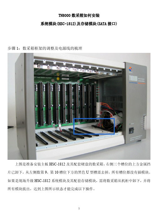
TN8000数采箱如何安装系统模块(HSC-1812)及存储模块(SATA接口)步骤1:数采箱框架的调整及电源线的梳理上图是准备安装主板HSC-1812及其配套硬盘的数采箱,右侧三个槽位的上方金属挡片已卸下,从左侧数第9,第10槽位下方的黑色U型槽需去掉,所有槽位都没有插模块。
如果是现场升级HSC-1812系统模块及其配套存储模块,需将数采箱从机柜中卸下,并将所有模块拔出,达到上图所示状态才能完成以下操作。
将上图所示9处螺丝拧松,但不要拧下来,将总线板按箭头所示方向下挪。
使所有螺丝达到如图所示状态后拧紧。
注:因为HSC-1812系统模块及其配套存储模块的上侧金属挡片略厚,以上步骤主要保证总线板上方留的空隙足够大,方便模块插拔。
再将上图所示8个螺丝卸下。
将塑料壳向右平推。
平推到底后可轻轻拉出壳体。
上图是壳体下方的固定件,它是L型结构,所以我们之前的操作一定要先平移再向外取出壳体,不要暴力拆卸,以免损坏固定件。
接下来查看一下数采箱电源提供的电源接口,是否有给SATA硬盘的供电接口。
因为数采箱电源批次的关系,2012年前的数采箱电源是不带SATA硬盘的供电接口的,下面将针对两种电源的情况分别进行介绍。
先介绍电源自带接口的情况。
将SATA电源接头抽出。
按蓝框所示将前一段的接头剪掉。
剪掉后效果如图。
如图所示将接头从电源控制线(黑绿双绞线,部分电源控制线为4芯或其他颜色)下方穿过。
拿一根扎带按图中位置穿过电源散热孔。
按如图所示扎紧。
扎好后效果如图,注意留好电源线的长度,超出数采箱部分刚好可以手持即可,这样既方便了电源线的插拔,将来也不会因线留的太长,塞满了存储模块与数采箱电源的空隙,造成安装和更换时的麻烦。
下面介绍数采箱电源没有SATA电源接口的情况。
如图所示我们需要添加一个电源转接头。
如图所示抽出一根4P电源接头。
图中蓝框为下一步骤要操作的位置。
如图所示位置将带有软驱供电接口的前一段接头剪掉。
剪掉后效果如图。

Operator’s manualLong-seam automatic machine type 8000Version D. July 2009We reserve the right to make changes in this documentContents: PageCHAPTER 1: EU DECLARATION OF CONFORMITY (2)CHAPTER 2: GENERAL (3)CHAPTER 3: SAFETY ADVICE AND NOTICES (4)PERSONAL SAFETY (4)Applications: (5)Removal of safety devices: (5)Correct placement of work pieces: (5)CHAPTER 4: HOW THE MACHINE WORKS: (6)Sketch of the long-seam automatic machine: (6)Starting and stopping the machine: (7)Failure during start-up, operation or shut-down: (8)Maintenance: (9)Basic precautions: (9)Maintenance checklist: (11)Storage of this operator’s manual: (12)CHAPTER 5: ASSEMBLY AND DISASSEMBLY (13)Design and construction of the long-seam automatic welding machine: (13)Set-up: (14)Disassembly: (16)CHAPTER 6: TECHNICAL DATA: (17)External connections: (18)List of replacement parts – long-seam automatic machine (21)IMPORTANT SAFETY NOTICEAlways read the operator’s manual carefully and thoroughly before operating the machine. When working, always bear in the mind the directions and safety instructions. When installing and operating the machine, read and follow the safety directions stated in the chapter of this operator’s manual entitled SAFETY ADVICE AND NOTICES.This operator’s manual must always be available to the persons installing, operating and servicing the machine.Chapter 1: EU Declaration of ConformityManufacturerCompany name: Migatronic Automation A/SAddress: Knøsgaardvej 112DK-9440 Aabybro, DenmarkTelephone: (+45) 96 96 27 00Internet: www.migatronic-automation.dkhereby declares thatThe machineMake: Long-seam automatic welding machineType: 8000has been manufactured in compliance with the provisions of the COUNCIL DIRECTIVE of 14 June 1989 on mutual approximation of the laws of the member states on machines (89/392/EEC as amended by 91/368/EEC and 93/44/EEC) with special reference to annexe 1 of the Directive on essential health and safety requirements in connection with the design and manufacture of machines (cf. Statutory Order of the Danish Working Environment Authority (Arbejdstilsynet) No. 561 of 24 June 1994).25/8-2006 Keld KjeldgaardDate SignatureChapter 2: GeneralThe type 8000 long-seam automatic machine has been designed for the automatic welding of straight seams using either MIG/MAG or TIG/PLASMA welding methods.It comes fitted as standard with 2-way adjustable gun mounting, but can also come supplied with automatic gun lift, as well as automatic stop/start of the root gas.If power sources are used in connection with the machine, read the operating manual of the power source prior to starting work.Chapter 3: Safety advice and noticesPERSONAL SAFETYLight and heat emissionA welding arc emits radiation which is damaging to the human eye. Even short-term exposure to this radiation can cause permanent damage. Your eyes must be protected against powerful infraredradiation, as well as visible and ultraviolet light by using suitableradiation protection glass fitted in your welding helmet. Your skin may also be damaged by this radiation. Radiation can cause serious burns. Protect your skin by wearing the helmet, full-body working overalls and gloves. Warn other people in the vicinity of the welding area of the danger of radiation and flying sparks. If possible, screen the workplace off from the surrounding environment. Together with flying sparks, heat radiation from the electric arc and the molten pool constitute a fire risk. For this reason, do not perform welding in the vicinity of flammable materials. Do not put the torch down without first extinguishing the flame. Your working clothes must not contain easily flammable materials or have creases or open pockets which may collect sparks. Wear a fireproof apron if appropriate. After completion of the work, switch off at all socket outlets or at the main valve, and depressurize hose couplings.Welding fumesThe smoke and fumes generated by the welding process are hazardous to health. Therefore extraction systems must be installed in such a way that the fumes which arise during welding are removedeffectively. When fumes from degreasing agents are acted on byultraviolet radiation from the electric arc, this may produce very toxic phosgene gas. For this reason, all dissolvents, degreasing agents and other potential sources of such fumes must be kept away from the welding area. Avoid inhaling welding fumes and gases. Use benches with extraction or other extraction systems for removal of welding fumes and gases. Use oxygen masks if no such effective extraction system is possible.ElectricityAvoid making contact with live components.The voltages used in connection with welding are not high enough to pose a risk of serious electric shock. However, minor electric shocksmay result from damp overalls and the like, and these can frighten the welder, so potentially posing an indirect safety hazard. In particular, HFhigh-voltage ignition in TIG and PLASMA welding can generate powerful shocks and cause minor burns under the skin. Contact with live welding parts should therefore be avoided as far as possible. Always ensure that cable insulation, as well as insulation on the torch and machine pin and socket connectors, is fully intact. Always wear dry leather gloves, dry overalls and dry footwear. Furthermore, keep cables, torches and the welding machine itself dry at all times. It is important that the machine’s connections have been set up according to the applicable regulations (power cables, fuses and safety conductor/earth lead). Do not open the machine to expose the live parts. Service and maintenance requiring access to live parts of the machine must only be undertaken by properly qualified personnel. Never leave a dismantled machine connected to the mains supply.Applications:- TIG welding hoses (live cables) and torches must not be placed on the electronic control box.- Do not exceed the maximum dimensions for work pieces laid down in the operator’s manual.- The machine/equipment may only be run by operators who have been trained in its use and who have also worked through the operator’s manual.Removal of safety devices:- Safety devices may not be disabled or removed while the machine is in an operating condition.Correct placement of work pieces:- Prior to starting work with the machine, the operator must ensure that the work piece has been correctly placed and properly secured.Chapter 4: How the machine works:Sketch of the long-seam automatic machine:Type: 1100 1650 2000 2500 3000 3500 4000 5000 Dimensionsmm a 1585 2160 2540 3040 3560 4000 4510 5010 mm b 265 265 265 265 265 265 265 265 mm c 600 600 600 600 600 600 600 600 mm d 800 800 800 800 800 800 800 800 mm h 1240 1240 1240 1240 1240 1240 1240 1240 mm i 1760 2260 2760 3260 3760 4260 4760 5260 Wkpce1100 1650 2000 2500 3000 3500 4000 4500 length mmStarting and stopping the machine:Use the cross-supports (A) to set the welding gun to the correct position. On how to set the welding speed, pre-welding time, post-welding time etc., refer to the operator’s manual for the 4005 control system.Adjust the inductive sensors on the rails to the desired positions (see “Set-up” in chapter 5).For welding with cold wire feed, set the wire speed on the type KT4 (B) cold wire feeding unit. Refer to the separate operator’s manual for this. Set the switch on type 4005 control systems to manual or automatic return. Activate the start button on type 4005 control systems and perform the welding using the programmed data.Failure during start-up, operation or shut-down:If monitoring of the electric arc (arc control) and welding have been activated, the automatic machine will not start until the electric arc has been established.While the machine is in this waiting mode, the operator must be aware that it may start once the electric arc is started.Maintenance:Regular maintenance is important.This ensures:* A long service life for the machine* Safety* Operational reliabilityMany of the maintenance tasks are simple for the operator to perform himself and require just a little mechanical skill and a few tools. These tasks are described below. However, note that some maintenance tasks require special tools and expertise. Such tasks should be given to qualified Migatronic employees. Even if you are an experienced DIY-mechanic, we recommend that you hand over repairs and maintenance to Migatronic Automation A/S.Basic precautions:- Disconnect all mains power before working on electricalinstallations or components.- Make sure you keep the work area clean and tidy.- Disconnect the power and air supply to the machine when it isnot in use or is left unattended.DAILY CHECKS BEFORE START-UPInspect the control system:A. Check that all power and fuse lamps light up.B. Ensure that the plug is properly inserted in the rear.C. Perform a cycle without doing any welding.Check mains leads, earth cables, air and gas hosesA. Check for external damage.B. Check for loose connections, elements or leaks.Welding control:Weld a work piece and compare to the one you retained from the same time the day before. If everything is OK, retain the piece you just welded for start-up on the following day.WEEKLY CHECK-UPClean all important surfaces using compressed air and lubricate sparingly with machine oil. Sign the maintenance checklist.MONTHLY CHECK-UPIn addition to the weekly inspection, check all nuts and Unbrako screws – especially on ball bearings, gun mounting and roll guides.Release carbon in the carbon holder (if any is fitted) and clean with compressed air, checking the carbon length.Check gear motors for leakage in gear gaskets and check wires. Check for play in main bearings.Clean the power sources internally (remember to remove the mains lead!). Sign the maintenance checklist.Maintenance checklist:Date Weekly check-up Monthly check-up Comments Init.Storage of this operator’s manual:Keep this operator’s manual in a place accessible at all times to operators, maintenance personnel and repairmen.Chapter 5: Assembly and disassemblyDesign and construction of the long-seam automatic welding machine:The machine is constructed to include carriage (A) which runs on rails on smooth-running roll guides, which are fitted on a robust RHS (B).The propulsion is provided by means of an electronically-controlled gear motor, which pulls the carriage via a toothed belt. Carriage engagement on the toothed belt can be released using a simple grip (C) for rapid relocation of the carriage. A welding gun and control system (D) are mounted on the carriage and the same is ready for the mounting of MIG/MAG or TIG wire feed.The machine is supplied as standard with a 2-way adjustable gun mounting (E).Set-up:Rear of control systemSensors / valves MotorStart welding machineWelding machine earthcableTo move/adjust the inductive sensors, turn the hand-clips (A) a quarter turn. This allows you to then flip the shielding down. Warning! Disconnect all mains power before flipping the shielding down.Working sensor – leftWorking sensor – rightEnd stop sensor – leftEnd stop sensor – rightThe illustration above shows the rails without shielding. After final adjustment, flip the shielding into place again.Warning!Do not leave the long-seam automatic machine in a dismantled condition.Disassembly:The old machine contains reusable parts.For this reason, do not send your automatic machine to the nearest tip; instead, contact your local council or an auto or scrap dealer about the possibility of reusing parts. Disconnect all external connections (electrical, air etc.) before disassembly.Chapter 6: Technical data:Type: 1100 1650 2000 2500 3000 3500 4000 5000 Dimensionsmm a 1585 2160 2540 3040 3560 4000 4510 5010 mm b 265 265 265 265 265 265 265 265 mm c 600 600 600 600 600 600 600 600 mm d 800 800 800 800 800 800 800 800 mm h 1240 1240 1240 1240 1240 1240 1240 1240 mm i 1760 2260 2760 3260 3760 4260 4760 5260 Wkpce1100 1650 2000 2500 3000 3500 4000 4500 length mm18 External connections:1920Please note that some part in this diagramme are mounted as options, and are not standard.List of replacement parts – long-seam automatic machinePos. no. Description Article number1 Unbrako screw M8x80 40310880-12 Toothed belt pulley 47419422-13 Seeger-A-ring 42510020-14 Shaft for toothed belt pulley. 25403005-15 Ball bearing 44166204-16 End stop sensor – left 17100809-17 Working sensor – left 17100809-18 Guide rail 45032049-19 Toothed belt type 1100Toothed belt type 1650Toothed belt type 2000Toothed belt type 2500Toothed belt type 3000Toothed belt type 3500Toothed belt type 4000Toothed belt type 4500 47041250-1 47041700-1 47042000-1 47042400-1 47042800-1 47043150-1 47043550-1 47043950-110 Carriage 45032040-111 Key fitting for sensor 27111002-112 Contact lever 45080032-113 Working sensor – right 17100809-114 End stop sensor – right 17100809-115 The engine and gearbox, depending on speedMotor 0.25 kW / 1350 rpm Gear i = 240Motor 0.12 kW / 660 rpm Gear i = 300 (TIG / Plasma) Gear i = 114 (MIG / MAG) 17290070-1 17290071-1 17290073-1 17290072-1 17290074-116 Taper lock bushing 46341526-1。

CPT-8000系列手持终端使用说明书公司简介欣技资讯股份有限公司,成立于1988年,在台湾是条码行业为数不多的上市公司.主要从事设计、生产以及销售自动识别与数据采集产品及系统。
公司致力于服务全世界的企业,寻求增加操作便利性和创造商业价值。
欣技资讯目前在欧洲、美洲、澳洲和亚洲都有分公司和合作者。
这个不断成长的营销网络可以迎合在不同的领域和工业应用上的各种需求,公司的主要产品都以CipherLab为商标名称。
欣技投入极大的资源致力于研究光学、电子学、机械工程学、通信技术、软件以及工业应用。
公司的工程师凭借渊博的知识和丰富的经验与他们的合作者们紧密协作在设计、工艺和系统上来满足广大客户的需求,并提供及时有效的服务。
公司为了增加效率,保证质量,在制造能力和加工处理上投入了很多的精力。
欣技产品通过了ISO9001的鉴定,为大家提供物美价廉的产品,并能灵活及时的交货。
合作和OEM欣技产品的公司有很多,包括卡西欧、日本精工株式会社、7-Eleven、美国康柏公司、Family Mart、先锋和码捷。
产品简介欣技CPT-8000系列手持终端外形优雅、体积轻巧,可使用“C”、“BASIC”,和基于Windows的应用程序产生器进行程序开发。
红外线、RF基站、串行接口多种可选传输方式。
抗摔、抗震、抗干扰能力强,适用于库存货物管理、货物流通管理等场合,是理想的零售业应用。
CPT-8000系列包括如下产品:CPT-8000L(激光)、CPT-8000C(红光)、CPT-8001L(激光)、CPT-8001C(红光)。
装箱清单1.欣技数据采集器一台2.通讯底座一个3.使用手册一本4.光盘一张如发现上述物品不全,请您与当地经销商联系目录1注意事项 (5)1.1使用事项 (5)1.2售后服务承诺 (6)2组件说明 (7)2.1CPT8000标准配置 (7)2.2CPT8001标准配置 (8)2.3CPT8000/8001选配设备 (9)2.4各部件说明 (9)3CPT8000系列规格说明 (10)4使用入门 (13)4.1按键功能 (13)4.2电源 (14)4.2.1CPT8000电池的安装 (14)4.2.2CPT8001电池的安装 (14)4.2.3充电底座的安装 (15)4.3手提带 (16)4.4条形码阅读操作 (17)4.5系列菜单及设置 (18)4.5.1版本信息 (18)4.5.2时钟设置 (18)4.5.3背光设置 (19)4.5.4CPU速度设置 (20)4.5.5自动关机设置 (20)4.5.6开机模式 (21)4.5.7按键提示音设置224.5.8密码设置224.5.9字体234.5.10恢复系统默认设置244.6系统测试244.7内存254.8电源 (25)4.9程序下载 (26)5故障排除 (27)5.1不能正常开机 (27)5.2显示屏不显示 (27)5.3字体显示不正常 (27)5.4不能传输数据或程序 (28)5.5工作不正常 (28)6CPT8000系列光盘 (28)1注意事项1.1使用事项显示屏机器保养请勿重压或撞击显示屏,以免请用干软的布清洁保养本机。
伟福®伟福Lab8000系列单片机仿真实验系统使用说明书南京伟福实业有限公司® 伟福 Lab8000单片机仿真实验系统 目录 - i -目 录第一章 概述 (1)第二章 伟福实验系统组成和结构 (3)1. 实验系统的硬件组成.............................................. (3)2. 实验系统的仿真板简介......... ......... ......... .. (15)3. 实验系统的调试方法......... ......... ......... ................... ....... .. (16)第三章 MCS51系列单片机实验 (17)MCS96系列单片机实验 (18)8088/86系列CPU 实验 (19)ARM LPC2103 MCU 实验 (20)PIC5X 系列CPU 实验 .............. .... . (20)软件实验1. 存储器块清零(51/96/88/PIC) (21)2. 二进制到BCD 码转换(51/96/88/PIC) (22)3. 二进制到ASCII 码转换(51/96/88/PIC) (23)4. 内存块移动(51/96/88/PIC) (24)5. 程序跳转表(51/96/88/PIC) (25)6. 数据排序(51/96/88/PIC) (26)硬件实验® 伟福Lab8000单片机仿真实验系统 目录 - ii -1. IO 口输入输出(51/96/PIC/ARM) (27)2. 继电器控制(51/96/PIC/ARM) (29)3. 用74HC245读入数据(51/96/88/ARM ) (30)4. 用74HC273输出数据(51/96/88/ARM) (31)5. PWM 转换电压实验(51/96/PIC/ARM) (32)6. 音频控制(51/96/PIC/ARM) (33)7. 用8255输入、输出(51/96/88/ARM) (34)8. 串行数转换并行数(51/96/PIC/ARM) (35)9. 并行数转换串行数(51/96/PIC/ARM) (37)10. 计数器实验(51/PIC/ARM) (39)11. 外部中断实验(51/96/ARM) (40)12. 定时器实验(51/96/PIC/ARM) (42)13. D/A 数模转换实验(51/96/88/ARM) (44)14. A/D 模数转换实验(51/96/88/ARM) ..................... . (46)15. 外部中断实验(急救车与交通灯) (51/96/ARM) (48)16. 八段数码管显示(51/96/88/PIC/ARM) (50)17. 键盘扫描显示实验(51/96/88/ARM) (52)18. 电子时钟(51/96/88/PIC/ARM) (54)19. 单片机串行口通讯实验(51/96/ARM) (56)® 伟福Lab8000单片机仿真实验系统 目录 - iii -20. 1-Wire 总线实验(51/96/PIC/ARM) (58)21. 直流电机控制实验(51/96/88/ARM) (60)22. 步进电机控制实验(51/96/88/PIC/ARM) (62)23. 温度传感器实验(51/96/88/ARM) (65)24. 液晶显示屏控制实验(51/96/88/ARM) (67)25. 电子琴实验(51/96/88/ARM) (68)26. 空调温度控制实验(51/96/88/ARM) (70)27. 计算器实验(51/96/88/ARM) (73)28. 用HSO 方式输出PWM 波形(96) (75)29. 用HSI 方式测量脉冲宽度(96) (76)30. 用HSI 中断方式统计脉冲个数(96) (77)31. 计数器实验(96) (79)32. 用片内A/D 做模数转换实验(96) (80)32. PWM 转换电压实验(88) (81)34. 8253计数器实验(88) (82)35. 8259外部中断实验(88) (83)36. 8253定时器实验(88) (85)37. 8251A 串行口通讯实验(88) (87)® 伟福Lab8000单片机仿真实验系统 目录 - iv -38. 8237 DMA 实验(88) (89)39. 压力传感器实验(51/96/88/ARM )............................…...................................91 40. 红外通讯实验(51/96/88/ARM)...............................……................................92 41. 16x16点阵显示实验(51/96/88/ARM).......................................................... ..9642. I2C 总线实验(51/96/PIC/ARM).. ................................................................. ..9843. SPI 总线实验(51/96/PIC/ARM) ............................................................. ... . (100)第四章 ARM LPC2103仿真板说明........................................................................... (101)在KEIL 和ADS 开发环境中安装LAB8000的驱动.............................. . (103)在KEIL 开发环境中安装LAB8000的驱动..….................. ..... ...... ............... ..106调试时可能出现的错误信息及原因................. ........... .................................. (110)第五章 逻辑分析工具 (111)第六章 系统自检功能..............................................…….............................................. .114® 伟福Lab8000单片机仿真实验系统 目录 - v -本实验说明书包括8051、80C196、8088/86、ARM 、PIC57五种MCU 的实验说明(MCS51有6个软件实验、31个硬件实验,MCS96有6个软件实验、35个硬件实验,8088/86有6个软件实验、25个硬件实验,PIC57有6个软件实验、14个硬件实验,ARM 提供了32个硬件实验)。
第十章典型故障案例10.1 某电厂200MW机组接长轴不平衡故障某电厂#3机组为国产200MW机组,大修时更换了接长轴,大修结束后,在第一次开机过程中接长轴两侧3瓦和4瓦的振动在过临界后迅速增大,3000rpm定速后振动继续增大,带上负荷后振动开始有所减少,约一小时后振动继续爬升,后被迫停机。
图一为机组开机和稳速过程振动变化情况。
通过对TN8000系统监测得到的数据进行分析,可以知道振动有以下特点:1、振动在过临界后迅速增大,振动与转速成正比关系;2、一倍频信号占振动的主要成分,波形为正弦波;3、振动主要体现在接长轴两侧,其它轴瓦基本正常。
TN8000系统自动诊断结果为接长轴不平衡,与现场专家通过对有关数据的分析得出的结论一致。
最后机组的接长轴被迫重新拆下,运回厂家做动不平衡,重新启机后振动基本正常。
图10.110610.2 某发电厂125MW机组碰磨故障某发电厂#4机组为上海汽轮机厂生产的125MW机组,2002年1月开始的大修中对通流部分进行了改造,同时安装了华科同安公司的TN8000系统。
在2002年3月大修结束后第一次开机过程中振动正常,但定速后低压缸前侧3瓦振动开始爬升,约一小时后振动达到250um,导致跳机,后被迫停机。
暖机一段时间后再次冲转,振动变化趋势与上次冲转基本一致。
通过对TN8000系统监测得到的数据进行分析可以知道振动有以下特点:1、从波特图(图10.2)中可以看出,开机过程和停机过程的振动和相位发生很大变化;2、一倍频信号占振动的主要成分,波形为正弦波;3、振动变化与转速无关。
由上述振动特征结合现场相关信号可以分析得出低压缸存在碰磨。
后揭开低压缸发现低压缸机座的滑销系统不正常,导致碰磨,处理完后重新启机振动基本正常。
图10.2107图10.310810.3某发电厂200MW机组低压转子不平衡故障某发电厂#4机组为国产200MW机组,2000年11月开始进行大修,同时安装了华科同安公司的TN8000系统。
INDUSTRIAL PUMP 8000 SERIESInstallation and Operation ManualSHURflo offers various pump models for different applications. The information outlined by this manual is general, and not specific to all 8000 series pumps. Be certain the pumps' materials will be compatible with the fluid being pumped. 8000 series pumps are intended for intermittent or continuous duty when the proper operating criteria is met. Product Data Sheets outlining specific thermal limits, load, flow curves, and other technical information for a particular model are available. If unsure of the chemical compatibility with a given elastomer or the motors intended design, please call SHURflo for assistance.C A U T I O N:"Intermittent Duty" is defined as; operated and/or frequently started within a period of time that would cause the motor to reach its maximum thermal limits. Once the maximum thermal limit is obtained, the motor must be allowed to return to ambient temperature before resuming operation.C A U T I O N:DO NOT use to pump flammable liquids. Never operate the pump in an explosive environment. Arcing from the motor brushes, switch or excessive heat from an improperly cycled motor may cause an explosion.C A U T I O N:DO NOT assume fluid compatibility. If the fluid is improperly matched to the pumps' elastomers, a leak may occur. Pumps used to transfer hazardous or hot (max. temperature 170°F [76°C] Viton™ only) chemicals must be in a vented area to guard against the possibility of injury due to harmful or explosive liquid/vapors.CAUTION:DO NOT operate the pump at pressures which cause the motor to exceed the amperes rating indicated on the name plate. Various pump models are equipped with thermal breakers to interrupt operation due to excessive heat. Once the temperature of the motor is within proper limits it will 911-314 Rev. N 1/98Page: 1 of 8automatically reset, and the pump will start operation without warning.CAUTION:To prevent electrical shock, disconnect power before initiating any work. In the case of pump failure, the motor housing and/or the pumped fluid may carry high voltage to components normally considered safe.PRESSURE SWITCH OPERATION(If Equipped)The pressure switch reacts to outlet pressure, and interrupts power at the preset shut-off pressure indicated on the pump label. When outlet pressure drops below a predetermined limit (*typically 15-20 psi. [1-1.4 bar] less than the shut-off pressure), the switch will close and the pump operates until the shut-off (high) pressure is achieved. The shut-off pressure is set to factory calibrated standards.CAUTION:Improper adjustment of the pressure switch setting, may cause severe overload or premature failure. Refer to SHURflo Service Bulletin #1031 for the adjustment procedure. Failures due to improper adjustment of the pressure switch setting will not be covered under the limited warranty.If the plumbing is restrictive or the flow rate is very low, the pump may re-pressurize the outlet faster than the fluid is being released, causing rapid cycling (*ON/OFF within 2 sec.). If the pump is subjected to rapid cycling during normal operation, or for infrequent periods, damage may occur.Applications which exhibit rapid cycling should have restrictions in the outlet minimized. If not feasible consider a SHURflo Accumulator or a SHURflo "bypass" model pump.BYPASS OPERATION(If Equipped*)A bypass pump may be used in application that would normally induce frequent start/stop of the motor, and thereby create a potential for overheating. Models equipped with an internal bypass are designed to pump at high pressure while at low flow rates. Bypass models equipped with a switch may operate for several seconds even though the discharge side has been closed off. Models equipped with a bypass only will continue to run until power is turned OFF.MOUNTING•The 8000 series pumps are self priming. Horizontal and vertical prime vary depending on the fluid viscosity and pump configuration. Refer to the pumps Product Data Sheet.•The pump should be located in an area that is dry and provides adequate ventilation. If mounted within an enclosure, provisions to cool the motor may be necessary. Heat sinks which attach to the motor are available from SHURflo if increased heat dissipation is necessary.CAUTION: DO NOT locate the motor near low temperature plastics or combustible material. The surface temperature of the motor may exceed *250°F [120°C].•The pump may be mounted in any position. However, if mounting the pump vertically the pump head should be in the down position so that in the unlikely event of a leak, fluid will not enter the motor.•Secure the rubber feet with #8 hardware. DO NOT compress the feet, doing so will reduce their ability to isolate vibration/noise. PLUMBING•Use flexible high pressure tubing compatible with the fluid to connect the inlet/outlet ports. Tubing should be either 3/8" or 1/2" [10 or 13 mm] I.D., and at least 18 in. [46 cm] length is suggested to minimize stress on the fitting/ports and reduce noise. Allow for the shortest possible tubing route and avoid sharp bends that may kink over time.•Installation of a 50 mesh strainer is recommended to prevent foreign debris from entering the system. Failures due to foreign debris is not covered under the limited warranty.NOTE:Restrictions on the inlet may cause vacuum levels to reach the fluid vapor pressure, causing cavitation, degassing,vapor lock and a loss in performance. Inlet pressure mustnot exceed 30 psi [2.1 bar] maximum.•If a check valve is installed in the plumbing it must have a cracking pressure of no more than 2 psi [.14 bar].NOTE: SHURflo does not recommend the use of metal fittings or rigid pipe to plumb the inlet/outlet ports. Standard plastic male and female threaded fittings can be acquired at commercial plumbing supply stores. SHURflo also distributes Swivel Barb Fittings, and special fittings through our dealers (Form #07-010-0011).•3/8" Female NPT models: In some cases, the ports may require a suitable thread sealer applied sparingly. DO NOT over-tighten, max. torque 3.7 ft\Lb (45 in\Lb ) [5 Nm].•1/2" Male threaded models: Are intended to be used with SHURflo Swivel Barb Fittings which seal with an internal taper when hand tightened. Standard 1/2" NPT fittings may be used when tightened to a max. torque of 3.7 ft\Lb (45 in\Lb) [5 Nm]. CAUTION:Sealers and Teflon tape may act as lubricant causing cracked housings or stripped threads due to over tightening. Care should be used when applying sealers, it may enter the pump inhibiting valve action, causing no prime or no shut-off. Failures due to foreign debris is not covered under warranty.•Snap-Lock models: The slide fittings are open when the slide is moved out toward the switch. Fittings should be inserted flush against housing port before the slide is moved to the locked position. Fittings of Nylon or Polypropylene are available in various sizes.ELECTRICALCAUTION:Electrical wiring should be performed by a qualified electrician, in accordance with all local electrical codes.•Improper duty cycle and/or rapid start & stop conditions may cause the internal thermal breaker (if equipped) to trip, or can result in premature motor failure due to excessive heat. Refer to the pumps Product Data Sheet.•The pump should be on a dedicated (individual) circuit, controlled with a double pole switch (UL/C-UL certified) rated at or above the fuse ampere indicated by the pump motor label. Depending on distance of the power source from the pump and ampere load on the circuit, wire may need to be heavier than indicated by the chart.CAUTION:All 115 VAC and 230 VAC pump motors and systems, MUST be ground per local and state electrical codes.•For the pump to meet UL/C-UL requirements the circuit MUST be protected with a slow-blow fuse(UL/C-UL certified) or equivalent circuit breaker as indicated on the motor label. Use an approved wire of the size specified or heavier.VOLTAGE MODEL FUSE (amp)WIRE LEADS WIRE SIZE12 DC800X-X4X-XXX15.08005-X5X-XXX 2.524 DC8005-X9X-XXX RED (positive +)#14 AWG [2.5 Mm2]800X-X5X-XXX10.0BLACK (negative -)(or heavier)36 DC800X-X8X-XXX 5.08005-X5X-XXX 1.5800X-X1X-XXX 1.25BLACK (common/hot)115 AC800X-X2X-XXX WHITE (neutral)800X-X3X-XXX 1.0GREEN (ground)#18 AWG800X-X6X-XX C-UL / TEW 1015800X-X0X-XXX0.8BROWN (common/hot)(or heavier) 230 AC809X-X0X-XX BLUE (neutral)[1 Mm2]•800X-X9X-XXX0.5GRN/YELL (ground)809X-X1X-XX•VDE requires a fuse (slow blow) or equivalent circuit breaker.CAUTION: Circuit protection is dependent on the individual application requirements. Failure to provide proper overload /thermal devices may result in a motor failure, which will not be covered under the limited warranty.*The information outlined by this manual is general, and not specific to all 8000 series pumps. Contact the factory for a Product Data Sheet outlining technical information for a particular model.TROUBLESHOOTINGPUMP WILL NOT START:ü Fuse or breakerü For correct voltage (±10%) and electrical connectionsü Pressure switch operation and correct voltage at switch or motor wires (as equipped).ü Rectifier or motor for open or grounded circuitü For locked drive assemblyWILL NOT PRIME: (No discharge/motor runs)ü Out of productü Strainer for debrisü Inlet tubing/plumbing; severe vacuum leakü Inlet/Outlet tube severely restricted (kinked)ü Debris in pump inlet/outlet valvesü Proper voltage with the pump operating (±10%)ü Pump housing for cracksLEAKS FROM PUMP HEAD OR SWITCH:ü For loose screws at switch or pump head.ü Switch diaphragm ruptured or pinched üFor punctured diaphragm if fluid is present at bottom drain holes.PUMP WILL NOT SHUT-OFF: (Pressure switch equip.)ü Output line closed and no leaksü For air trapped in outlet line or pump headü For correct voltage to pump (±10%)ü Inlet/Outlet valves for debris or swelling ü For loose drive assembly or pump head screwsü Pressure switch operation/adjustment incorrect refer to S/B #1031 fordifferential and pressure adjustmentprocedureNOISY / ROUGH OPERATION:ü Mounting feet that are compressed to tightü For loose pump head or drive screwsü Does the mounting surface multiply noise (flexible)ü Is the pump plumbed with rigid pipe causing noise to transmitSERVICE KITSKits are readily available to repair standard 8000 series pumps. Repair kits include simple illustrated instructions allowing easy installation. To insure that the correct kit is received the model numbered and all name plate data must be included with the order. Contact a SHURflo distributor or SHURflo directly to order the necessary repair kit.KEY#DESCRIPTION1Complete assembled pump head2Pressure switch assembly3Check valve components4Upper housing5Bypass valve and discharge valve assembly 6Valve plate assembly7Diaphragm and piston components8Drive assembly9Motor assembly (less base plate)INDUSTRIAL PRODUCT LIMITED WARRANTYSHURflo Industrial series pumps and products are warranted to be free of defects in material and workmanship under normal use, for a period of one (1) year from the date of manufacture, or one (1) year of use, with proof of purchase. This limited warranty will not exceed two (2) years, in any event.The limited warranty will not apply to pumps/products that were improperly installed, misapplied, damaged, altered, incompatible with fluids or components not manufactured by SHURflo.All Industrial pumps/products must be flush of any chemicals before shipping². All warranty considerations are governed by SHURflo's written Return Policy.Returns are to be shipped postage prepaid to either service center; SHURflo Garden Grove, CA or Elkhart, IN. SHURflo shall not be liable for freight damage incurred during shipping. Package returns carefully. SHURflo's obligation under this warranty policy is limited to the repair or replacement of the pump/ product. All returns will be tested per SHURflo factory criteria. Products found not defective (under the terms of this limited warranty) are subject to charges paid by the returnee for the testing and packaging of "tested good" non-warranty returns.No credit or labor allowances will be given for pumps or products returned as defective. Warranty replacements will be shipped on a freight allowed basis. SHURflo reserves the right to choose the method of transportation.This limited warranty is in lieu of all other warranties, expressed or implied, and no other person is authorized to give any other warranty or assume obligation or liability on SHURflo's behalf. SHURflo shall not be liable for any labor, damage or other expense, nor shall SHURflo be liable for any indirect, incidental or consequential damages of any kind incurred by the reason of the use or sale of any defective product or part. This limited warranty covers industrial products distributed within the United States of America. Other world market areas should consult with the actual distributor for any deviation from this document.RETURN POLICYAll Industrial pumps/products must be flushed of any chemical (ref. OSHA Section 1910.1200 (d)(e)(f)(g)(h)) and hazardous chemicals must be labeled / tagged before being shipped² to SHURflo for service or warranty consideration. SHURflo reserves the right to request a Material Safety Data Sheet from the returnee for any pump/product it deems necessary. SHURflo reserves the right to "disposition as scrap" pumps/products returned which contain unknown fluids. SHURflo reserves the right to charge the returnee for any and all costs incurred for chemical testing, and proper disposal of components containing unknown fluids. SHURflo request this in order to protect the environment and personnel from the hazardsof handling unknown fluids.² Carriers, including U.S.P.S., airlines, UPS, ground freight, etc., require specific identification of any hazardous materials to be shipped. Failure to do so may result in a substantial fine and/or prison term. Check with your shipping company for specific instructions.«SHURflo reserves the right to update specifications, prices, or make substitutions.SHURflo «12650 Westminster Ave.Santa Ana, CA 92706-2100 (800) 854-3218 (714) 554-7709FAX (714) 554-4721 Shipping/UPS: 12650 WestminsterAve.Garden Grove, CA 92843SHURflo East52748 Park Six CourtElkhart, IN 46514-5427((800) 762-8094(219) 262-0478FAX (219) 264-2169SHURflo Ltd.Unit 5 Sterling ParkGatwick Road, CrawleyWest Sussex, RH10 2QTUnited Kingdom+44 1293 424000FAX +44 1293 421880。
第九章相关知识由于振动监测系统从传感器直接获取的信息往往是杂乱无章的,其特征不明显、不直观,很难加以判断。
因此一般振动监测系统通常利用计算机采集到的信息,通过一定的方法进行变换处理,以获取最敏感、最直观、最有用的特征信息,然后通过各种分析图谱显示出来。
用户可以通过分析图谱来了解机组运行状态及分析机组故障原因。
下面对振动监测系统中常见的监测参量、分析图谱和名词做一些介绍。
9.1 振动参量振动是一个综合信息,通常所说的振动是指振动的幅值。
实际上振动包含下列振动参量:振幅:是指一个振动周期的全幅值,可表达为位移、速度和加速度,它是振动强度的标志。
过去的振动监测手段仅限于对轴承座振幅的监测,并已形成了习惯,目前国内在运行的大量机组均沿用这一传统的监测手段。
但现代技术早已发展到监测转轴的相对振动和绝对振动。
轴振动能更直观更准确地表明机器故障的存在,因此为了全面保护机组,必须开展轴振动监测。
通常一台正常运转的机组,有一个稳定的、良好的低振幅值,这是我们判断机组是否正常的基点。
作为一个运行人员,关注的主要不是这一幅值是否超过允许值,而是这一幅值的变化幅值(增量和减量)是否在允许的范围内。
这涉及到观念的变化,以后还要详细论述。
频率:振动频率(周/秒)通常表示为机器转速的倍数。
频率是分析机器故障的重要参量,有助于对故障进行分类,再对照其它参量进行分析,可较为准确地判断出故障的原因。
但某一特定频率是和多种机器故障相联系的。
它们间不存在一一对应的关系,这一点在进行振动故障原因分析时,必须特别注意。
相位:相位用来描述某一特定时刻机器转子的位置。
相位测量系统能够确定每一传感器信号上对应的机器转子的“高点”相对转子上某一固定点的位置。
通过确定机器转子上“高点”的位置,就可能确定机器的平衡状态和转子上残留的不平衡重量的位置。
转子平衡状态的改变将引起“高点”方位的变化,这种变化通过相位变化而显示出来。
因此,相位测量对于转子动平衡和设备故障分析均非常重要。
振动形式:通过对振动形式的观测,能直观地了解机器的运行状态。
振动形式可以用两种方法直观地显示在计算机画面上。
时基形式:以转子上某一测点位置为纵坐标、时间为横坐标的关系曲线。
一般振动信号为正弦波形。
通过观测时基振动形式,能够确定基本的振幅和频率。
轴心轨迹:由两个互成90°的非接触式传感器所感受到的振动信号合成。
所显示的是对应于两传感器的轴截面中心点的运动,若传感器安装在轴承上,则轴心轨迹时轴的中心线相对于轴承的运动关系,能够反映轴的实际运动情况。
振型:是指转轴在一定的转速下,沿轴向的一种变形。
比如一阶振型类似抛物线,二阶振型类似正弦波等等。
测量沿转轴的轴向每隔一定间距的轴截面中心线振动情况,便可综合出转轴的振型。
对于柔性转子为说,工作转速时,一般接近二阶振型,即转子挠度线平衡最为合理。
这里需要强调的是,对于全面了解机组的运行状态和分析机组故障来说,测量轴振动和轴承座振动、测量轴的相对振动绝对振动以及在相互垂直的两个方向上测量振动都是十分重要的。
9.2 工况参量为了监测分析机组的运行状态,仅有振动参量是不够的,还必须综合监测其它参量,例如需测转速、负荷、转轴位置、压力、温度、流量等参量。
下面分别作介绍。
9.2.1位置参量:轴在轴承内的偏心位置、即径向平均位置。
转轴在滑动轴承中旋转时,形成的契形油膜偏向于轴承中心线的一侧,即产生一偏心距。
此偏心距的大小和方位影响到轴承的稳定性,还可以对照其它参量,用来分析轴承磨损、冷热态中心偏移等情况。
因此在机组启动期间及正常运行后要进行连续监测,并对照基准点作比较,可以及时发现机组故障。
转子轴向位置:即推力盘在推力轴承中的相对位置。
用以监测汽轮机通流部分轴向最小间隙的变化;并可监测推力轴承与乌金面的磨损情况,轴承在瓦枕中的移动量也能反映出来。
若探头松动或锈蚀,测出的数据将会异常。
有时通流部分故障会在轴向推力上反映出来,因而转子轴向位置也可作为分析通流部分状况的参量之一。
若有必要,还可用同一探头监测转子轴向振动,这对于分析某些特殊故障很有价值。
偏心度:又称挠度、晃度。
是对转轴在静态时弯曲值的测量。
这是机组启动前必须要监测的重要参量。
只有当转子的静弯曲值在允许范围内,并在一定时间段内不变化,机组才允许启动。
胀差:即机组动静部分相对于各自死点膨胀量的差值。
对于现代汽轮机来说,一般分析测量高、中、低压胀差。
制造厂依据计算出的由静止到满负荷时汽缸和转子的膨胀曲线,限定测点处的胀差值允许范围。
在此范围内,汽轮机通流部分一般不致发生动静部分摩擦,因而是机组启停和正常运行时必须监测的重要参量。
汽缸绝对膨胀、即汽缸相对于死点的膨胀量。
因低压缸膨胀量很小,且死点在低压缸上,故一般仅监测中压缸绝胀和高压缸绝胀。
对于单死点机组,高压缸绝胀实际上是整个机组和膨胀量。
对于高、中合缸机组,仅监测合缸的膨胀量。
若汽缸膨胀不畅,轻则引起通流部分磨损和异常振动,重则导致大轴弯曲等设备损坏事故,因此,绝胀也是机组启停时和正常运行中必须监测的重要参量。
轴承座位置变化:即热态中心(相对于冷态)的变化,影响轴承的负荷分配,因而也就影响到轴系的稳定性。
从西方引进的机组,制造厂一般会提供冷态找中心时的预留值,以补偿热态时的变化。
冷热态中心的变化是一个三维空间的位移量,而且变工况的影响较大,目前尚无很准确的测量办法。
用间接推断并逐次渐近,可近似地确定冷态时的预留值。
相邻轴承座间位置的变化,对轴系稳定性的影响较大,可以用机械的办法进行较为准确的测量。
9.2.2 转速在对机器运行状态的分析中,确定振动和转速之间的关系是很重要的。
波特图:振幅——转速关系曲线和相位——转速关系曲线。
于机器启动或停止时测得,可用以确定机器的临界转速,分析机器是否出现异常。
临界转速:是机器固有特性的反映,工作转速在一阶临界转速以下的转子称为刚性转子,例如用于反动式汽轮机上的焊接转子,可以用低速动平衡的办法处理转子平衡问题。
工作转速在临界转速以上的转子称为挠性转子或柔性转子,如现代汽轮机转子和发电机转子,一般要采用高速动平衡的办法处理转子的平衡问题。
现代发电机转子的临界转速一般均在二分之一工作转速以下,具备产生油膜振动的条件。
9.2.3 温度作为振动分析的相关参量,最为关注的是主轴承和推力轴承乌金温度的监测。
要求下轴瓦轴向前后安装两个温度测点,可用以判断机组运行时轴瓦是否倾斜。
每个推力瓦块上均应装有温度测点,可判断各瓦块承受的轴向力是否超限。
9.2.4轴承油膜压力最早用于推力轴承瓦块承变载荷的监测,现在可通过各轴承的顶轴油压表监测机组正常运行时的相对油膜压力能直观地反映出轴承所承受的载荷,因而能直接了解到影响轴系稳定性的因素。
综合分析影响机器正常运行的各参量间的关系,就能对机器的运行状况有一个较为全面的了解,有助于制订出较为合理的预知维修方案。
9.3 波形图波形图是转子响应随时间的变化曲线,通常它近似为正波,是最原始的信号,所以包含的信息量大,具有直观、易于理解等特点,但不太容易看出所包含信息与故障的联系。
从波形图可推导出呈现在振动波形中的基本频率,借助于键相相位信号,时基线信号可被用作相位角的直接显示。
对于某些故障信号,其波形具有明显特征,这时可以利用波形图作出初步判断。
比如,当旋转机械其不平衡故障较严重时,信号中有明显的以旋转频率为特征的周期成分(即一倍频1X成分)(见图9.1);而转轴不对中时,信号在一个周期内,比旋转频率大一倍的频率成分(即二倍频2X成分)明显加大,即一周波动二次(见图9.2)。
在实际测量中,X、Y两个传感器中任一传感器,都可得到包含许多频率成分的通频波形图,如图9.3A所示,经过滤波可得一倍频信号,如图9.3中B所示,当然还可分解出二倍频、三倍频……等,其相互关系见图9.3中C所示。
图9.1 具有不平衡故障的波形图图9.2 具有不对中故障的波形图图9.3 波形信号通过波形图还可以分辨由于测量系统存在问题(如传感器安装位置不正确、轴表面存在缺陷、探头受干扰)而导致的振动问题。
图9.4为涡流探头受电磁影响后的振动波形。
图9.4涡流探头受电磁影响后的振动波形9.4 频谱图工程上所测得的信号一般为时域信号,然而由于故障的发生、发展往往引起信号频率结构的变化,为了通过所测信号了解、观测对象的动态行为,往往需要频域信号。
将时域信号变换至频域加以分析的方法称为频谱分析,如图9.5所示。
频谱分析的目的是把复杂的时间历程波形,经傅里叶变换分解为若干单一的谐波分量,以获得信号的频率结构以及各谐波幅值和相位信息。
图9.5 频谱分析频谱分析是机械故障诊断中用得最广泛的信号处理方法之一。
以频率f为横坐标,以幅值为纵坐标所得即为频谱图。
频谱图有离散谱(谱线图)与连续谱之分,前者与周期性及准周期信号相对应,后者与非周期信号及随机信号相对应。
对于汽轮发电机组的振动,无论是强迫振动还是自激振动,激振源大多数与转子的转速有关,激振力的频率往往是转速的整数倍或整分数倍。
对于线性的转子——轴承——支承系统,振动响应中必然包含这些激振力产生的频率分量;另一方面,对于多种自激振动,只有当激振力的频率与转子某个临界转速或支承系统固有频率接近时,才会激起大的振动。
所以,在传感器检测到的振动信号中,包含有对应于转子临界转速,支承系统固有频率和转速整数倍或整分数倍的简谐分量,当然也可能含有非线性产生的其它振动分量和随机噪音。
频谱分析就是对复杂周期信号逐一分离成各频率简谐分量,在振动分析和故障诊断中起着提取特征和压缩数据的作用,这是很有用的,因为某些故障能够引起具有特定频率的振动。
振动信号的频域分析可用模拟电路的带通滤波器或数字式离散傅氏变换(DFT或快速傅氏变换FFT),在现代以计算机或微机处理器为核心的振动分析仪和振动监测及诊断系统中,主要采用数字式傅氏变换。
9.5 相位测量长期以来在研究旋转机械时,人们并不把振动相位看成一个重要参量,但实际上,相位是很重要的。
相位测量可用来描述某一特定时刻机器转子的位置。
一个好的相位测量系统能够确定每一传感器信号上对应的机器转子的高点相对转子上某一固定点的位置。
通过确定机器转子上高点的位置,我们就可能确定机器的平衡状态和机器转子上残留的非平衡重量的位置。
机器转子平衡状态的改变将引起高点的变化,这种变化通过相位变化显示出来。
在平衡机器的转子时,相位测量非常重要,在分析机器的某一特殊故障时,相位测量也可能非常重要。
通过测定机器转子的相位数据,我们可以得到机器体系运行状态的宝贵资料。
测量相位的最准确可靠的方法是利用一个键相器(图9.6)。
所谓键相器就是在轴上开一键槽(图9.6A),或在轴上装一个键(图9.6B),二者选一。
用一电涡流传感器探头对准键槽或者凸台,这样,当传感器探头探到键槽时前置器即输出一负脉冲,如探测到凸台则前置器输出一正脉冲,在两个脉冲之间即为一转,因而通过键相可以测量转速。