英飞拓V2020矩阵(infonova V2020)Datasheet
- 格式:pdf
- 大小:747.83 KB
- 文档页数:2

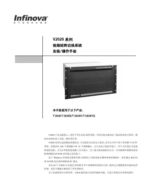
InfoLink DTX8200系列QAM调制器用户指南目录目录1 概述................................................................................................................................................ 1-11.1 简介............................................................................................................................................................... 1-21.2 特性............................................................................................................................................................... 1-31.3 工作原理....................................................................................................................................................... 1-42 设备描述........................................................................................................................................ 2-12.1 设备描述....................................................................................................................................................... 2-22.1.1 设备外观 ............................................................................................................................................. 2-22.1.2 前面板 ................................................................................................................................................. 2-22.1.3 功能键 ................................................................................................................................................. 2-22.1.4 后面板 ................................................................................................................................................. 2-32.2 接口描述....................................................................................................................................................... 2-42.3 设备操作菜单............................................................................................................................................... 2-53 安装指南........................................................................................................................................ 3-13.1 安装流程....................................................................................................................................................... 3-23.2 安装机箱....................................................................................................................................................... 3-23.3 连接线缆....................................................................................................................................................... 3-33.3.1 安装说明 ............................................................................................................................................. 3-33.3.2 连接地线 ............................................................................................................................................. 3-43.3.3 连接DS3输入和输出线缆................................................................................................................. 3-43.3.4 连接ASI输入和输出线缆 ................................................................................................................. 3-53.3.5 连接SPI输入线缆.............................................................................................................................. 3-63.3.6 连接IF中频输入/输出线缆 ............................................................................................................... 3-73.3.7 连接RF射频输出线缆....................................................................................................................... 3-83.3.8 连接10/100M网口 ............................................................................................................................. 3-93.3.9 连接电源线........................................................................................................................................ 3-103.4 启动设备..................................................................................................................................................... 3-114 配置设备参数................................................................................................................................ 4-14.1 配置概述....................................................................................................................................................... 4-24.2 选择输入接口............................................................................................................................................... 4-3目录InfoLink DTX8200系列QAM调制器用户指南4.3 设置DS3模式.............................................................................................................................................. 4-44.3.1 选择模式 ............................................................................................................................................. 4-44.3.2 设置主/备模式号 ................................................................................................................................ 4-54.3.3 搜索模式号.......................................................................................................................................... 4-6 4.4 输出设置....................................................................................................................................................... 4-64.4.1 设置输出频率...................................................................................................................................... 4-64.4.2 设置输出频道...................................................................................................................................... 4-74.4.3 设置QAM调制数 .............................................................................................................................. 4-84.4.4 设置符号率.......................................................................................................................................... 4-94.4.5 设置输出码率...................................................................................................................................... 4-94.4.6 设置射频控制.................................................................................................................................... 4-104.4.7 设置输出增益.................................................................................................................................... 4-114.4.8 设置频谱翻转.................................................................................................................................... 4-11 4.5 码流处理..................................................................................................................................................... 4-124.5.1 设置PID过滤 ................................................................................................................................... 4-124.5.2 设置PID映射 ................................................................................................................................... 4-134.5.3 设置PID插入 ................................................................................................................................... 4-155 配置网络参数................................................................................................................................ 5-15.1 组网简介....................................................................................................................................................... 5-25.2 设置网管IP地址 ......................................................................................................................................... 5-25.3 设置以太网口参数....................................................................................................................................... 5-35.3.1 设置IP地址 ........................................................................................................................................ 5-35.3.2 设置子网掩码...................................................................................................................................... 5-35.3.3 设置网关地址...................................................................................................................................... 5-45.3.4 设置网口模式...................................................................................................................................... 5-55.4 配置TS网口参数 ........................................................................................................................................ 5-55.4.1 打开网口 ............................................................................................................................................. 5-55.4.2 设置IP地址 ........................................................................................................................................ 5-65.4.3 设置子网掩码...................................................................................................................................... 5-65.4.4 设置网管PID ...................................................................................................................................... 5-75.5 配置透明传输网口参数............................................................................................................................... 5-75.5.1 透明传输示例...................................................................................................................................... 5-75.5.2 打开网口 ............................................................................................................................................. 5-85.5.3 设置IP地址 ........................................................................................................................................ 5-85.5.4 设置子网掩码...................................................................................................................................... 5-95.5.5 设置网关地址...................................................................................................................................... 5-95.5.6 设置网元IP ......................................................................................................................................... 5-95.5.7 设置源地址........................................................................................................................................ 5-105.5.8 设置目标地址.................................................................................................................................... 5-11InfoLink DTX8200系列QAM调制器用户指南目录6 典型业务配置................................................................................................................................ 6-16.1 配置复用....................................................................................................................................................... 6-26.2 配置调制....................................................................................................................................................... 6-57 升级指南........................................................................................................................................ 7-17.1 升级准备....................................................................................................................................................... 7-27.2 升级执行....................................................................................................................................................... 7-27.2.1 通过网管系统升级软件...................................................................................................................... 7-37.2.2 通过FTP服务器升级......................................................................................................................... 7-48 例行维护........................................................................................................................................ 8-18.1 设备例行维护项目....................................................................................................................................... 8-28.2 日维护项目................................................................................................................................................... 8-28.3 月维护项目................................................................................................................................................... 8-48.4 年维护项目................................................................................................................................................... 8-68.5 维护表........................................................................................................................................................... 8-78.5.1 日维护表 ............................................................................................................................................. 8-78.5.2 月维护表 ............................................................................................................................................. 8-88.5.3 年维护表 ............................................................................................................................................. 8-99 告警处理........................................................................................................................................ 9-19.1 告警信息处理............................................................................................................................................... 9-29.1.1 查看告警信息...................................................................................................................................... 9-29.1.2 保存告警信息...................................................................................................................................... 9-29.1.3 删除告警信息...................................................................................................................................... 9-29.2 常见告警及处理建议................................................................................................................................... 9-39.2.1 码流类告警.......................................................................................................................................... 9-39.2.2 升级类告警.......................................................................................................................................... 9-49.2.3 其它 ..................................................................................................................................................... 9-410 故障处理.................................................................................................................................... 10-110.1 输入输出故障处理................................................................................................................................... 10-210.1.1 射频信号无输出.............................................................................................................................. 10-210.1.2 射频信号输出偏低.......................................................................................................................... 10-210.1.3 设备输入码流中断.......................................................................................................................... 10-210.2 接收与显示节目故障处理....................................................................................................................... 10-310.2.1 STB不能正常解码节目.................................................................................................................. 10-310.2.2 混频后STB搜索不到节目............................................................................................................. 10-310.2.3 无电视信号...................................................................................................................................... 10-410.2.4 过滤后节目还存在.......................................................................................................................... 10-410.2.5 插入PSI/SI信息导致STB工作异常 ............................................................................................ 10-410.2.6 映射后的节目未能正常播放.......................................................................................................... 10-5目录InfoLink DTX8200系列QAM调制器用户指南10.2.7 图像显示马赛克或定帧.................................................................................................................. 10-5 10.3 网管管理设备故障处理........................................................................................................................... 10-610.3.1 网管不能提取PSI/SI信息 ............................................................................................................. 10-610.3.2 网管不能控制添加的设备.............................................................................................................. 10-610.3.3 网管软件未能成功提取PSI/SI表信息.......................................................................................... 10-711 FAQ ........................................................................................................................................... 11-111.1 名词解释FAQ .......................................................................................................................................... 11-211.2 操作应用FAQ .......................................................................................................................................... 11-3InfoLink DTX8200系列QAM调制器用户指南插图目录插图目录图1-1 DTX8200在数字电视前端的应用......................................................................................................... 1-2图1-2 DTX8200总体结构示意图..................................................................................................................... 1-4图2-1 DTX8200外观示意图............................................................................................................................. 2-2图2-2 DTX8200前面板示意图......................................................................................................................... 2-2图2-3 DTX8208后面板 .................................................................................................................................... 2-3图2-4 DTX8209后面板 .................................................................................................................................... 2-3图2-5 DTX8210后面板 .................................................................................................................................... 2-3图2-6 DTX8211与DTX8211E后面板............................................................................................................. 2-4图2-7 DTX8200接口图 .................................................................................................................................... 2-4图2-8 信息查询项 ............................................................................................................................................. 2-6图2-9 码流处理项 ............................................................................................................................................. 2-6图2-10 输出设置项 ........................................................................................................................................... 2-6图2-11 输入设置项............................................................................................................................................ 2-7图2-12 网络设置 ............................................................................................................................................... 2-7图2-13 系统设置 ............................................................................................................................................... 2-8图3-1 DTX8200安装流程................................................................................................................................. 3-2图3-2 DTX8200的固定 .................................................................................................................................... 3-2图3-3 连接地线 ................................................................................................................................................. 3-4图3-4 75Ω同轴线缆.......................................................................................................................................... 3-4图3-5 DS3输入、输出连接示意图.................................................................................................................. 3-5图3-6 ASI输入、输出连接示意图................................................................................................................... 3-6图3-7 SPI线缆................................................................................................................................................... 3-7图3-8 SPI线缆连接示意图............................................................................................................................... 3-7图3-9 IF输入、IF输出自环连接示意图......................................................................................................... 3-8图3-10 RF射频输出连接示意图...................................................................................................................... 3-9插图目录InfoLink DTX8200系列QAM调制器用户指南图3-11 10/100M网线 ........................................................................................................................................ 3-9图3-12 连接10/100M网口示意图 ................................................................................................................. 3-10图3-13 连接电源和地线.................................................................................................................................. 3-10图3-14 DTX8200启动显示............................................................................................................................. 3-11图4-1 设置过滤参数 ....................................................................................................................................... 4-13图4-2 设置映射参数 ....................................................................................................................................... 4-15图5-1 设置网口IP地址 .................................................................................................................................... 5-3图5-2 设置网口子网掩码.................................................................................................................................. 5-4图5-3 设置网关地址 ......................................................................................................................................... 5-4图5-4 设置网口模式 ......................................................................................................................................... 5-5图5-5 打开TS网口........................................................................................................................................... 5-6图5-6 设置TS网口IP地址.............................................................................................................................. 5-6图5-7 设置TS网口子网掩码 ........................................................................................................................... 5-6图5-8 设置网管PID .......................................................................................................................................... 5-7图5-9 透明传输示例 ......................................................................................................................................... 5-8图5-10 打开透明传输网口................................................................................................................................ 5-8图5-11 设置透明传输网口IP地址 .................................................................................................................. 5-9图5-12 设置透明传输网口子网掩码................................................................................................................ 5-9图5-13 设置透明传输网口网关地址................................................................................................................ 5-9图5-14 设置透明传输网元IP ......................................................................................................................... 5-10图5-15 设置透明传输网口源地址.................................................................................................................. 5-10图5-16 设置透明传输网口目标地址.............................................................................................................. 5-11图6-1 配置组网图 ............................................................................................................................................. 6-2图6-2 基本配置 ................................................................................................................................................. 6-3图6-3 提取表信息 ............................................................................................................................................. 6-4图6-4 复用接口配置 ......................................................................................................................................... 6-5图6-5 配置组网图 ............................................................................................................................................. 6-6图7-1 启动FTP服务器软件............................................................................................................................. 7-2图7-2 升级软件界面 ......................................................................................................................................... 7-3图7-3 选择升级软件 ......................................................................................................................................... 7-4图7-4 设置升级服务器IP地址 ........................................................................................................................ 7-4图7-5 启动程序升级 ......................................................................................................................................... 7-5InfoLink DTX8200系列QAM调制器用户指南表格目录表格目录表2-1 功能及方向键说明.................................................................................................................................. 2-2表2-2 设备接口描述 ......................................................................................................................................... 2-5表3-1 DTX8200安装可选项............................................................................................................................. 3-3表4-1 配置顺序 ................................................................................................................................................. 4-2表4-2 输入接口可选项...................................................................................................................................... 4-3表4-3 模式参数选择 ......................................................................................................................................... 4-5表4-4 DS3模式号.............................................................................................................................................. 4-6表4-5 可选项参数 ............................................................................................................................................. 4-7表4-6 输出频率规划 ......................................................................................................................................... 4-7表4-7 输出频道参数选项.................................................................................................................................. 4-8表4-8 QAM调制数参数选项 ........................................................................................................................... 4-8表4-9 符号率参数选项...................................................................................................................................... 4-9表4-10 输出码率参数选项.............................................................................................................................. 4-10表4-11 射频信号选项...................................................................................................................................... 4-10表4-12 输出增益选项 ..................................................................................................................................... 4-11表4-13 频谱翻转选项 ..................................................................................................................................... 4-12表4-14 PID过滤选项 ...................................................................................................................................... 4-12表4-15 PID映射选项 ...................................................................................................................................... 4-14表4-16 PID插入选项 ...................................................................................................................................... 4-16表5-1 网管组网方式 ......................................................................................................................................... 5-2表6-1 基本流PID .............................................................................................................................................. 6-2表8-1 设备例行维护周期和维护项目.............................................................................................................. 8-2表8-2 设备的日维护项目.................................................................................................................................. 8-3表8-3 指示灯状态及说明.................................................................................................................................. 8-4表8-4 设备的月维护项目.................................................................................................................................. 8-5。
i24 Product Technical White PaperRevision 3.0Release date: 2020-01Dear user:© Copyright Inspur 2017No part of this document may be replicated or modified and transmitted through any form or method without the prior written consent of Inspur.Note: Commercial contracts and terms apply to purchases of goods, services, or features from Inspur. All of some of the goods, services, or features mentioned in this document may not be within your scope of purchase of use. Unless agreed otherwise, Inspur will not indicate or imply any declarations or guarantees on the contents of this manual. Due to product upgrades or added details, the contents of this manual will be regularly updated. Unless agreed otherwise, this document shall only serve as a user manual. All descriptions, information, and suggestions shall not form any explicit or implicit guarantees.Inspur and "浪潮" are registered trademarks of Inspur Electronic Information Industry Co., Ltd.Windows is a registered trademark of Microsoft Corporation.Intel and Xeon are registered trademarks of Intel Corporation.Other trademarks belong to their respective registered companies.4008600011Technical servicenumber:Address: 1036 Langchao Rd., Jinan,Shandong, ChinaInspur Electronic InformationIndustry Co., Ltd.Postal code: 250101Contents1Product Overview (4)2Product features (5)3Logical architecture (7)4Product Introduction (8)4.1Internal View of Server Chassis (8)4.2Motherboard components (8)4.3Front panel (9)4.3.112*3.5 Front Panel Components (9)4.3.2Front Panel Controller (10)4.3.324*2.5 Front Panel Components (10)4.3.4Hard Drive (11)4.4Rear Panel (11)4.4.1Chassis and power supply (11)4.4.2Chassis components (12)4.5Hard drive backplanes (12)4.6PCIe adapter cards (13)4.7OCT/PHY cards (14)5System specifications (15)6Components and compatibility (18)6.1Processor (18)6.2Memory (19)6.3Storage (Realizing SAS/SATA mixing) (21)6.3.1SAS/SATA hard drive model (21)6.3.2 2.5” SSD hard drive (21)6.3.3U.2 NVMe SSD hard drives (21)6.3.4PCIe NVME SSD (22)6.3.5M.2 SSD (22)6.4RAID/SAS card (22)6.5Network Card (23)6.6HCA Card (23)6.7FC HCA Card (24)6.8Power Supply (24)6.9Operating system (24)7Configuration Options (25)8System management (26)9Certifications (29)10Support and services (30)11Description of New Technologies (31)11.1Intel scalable architecture (31)11.2Intel VROC technology (31)11.3QAT technology (31)11.4OCP Mezzanine Card (31)12Further Information (32)13Trademark (33)1 Product OverviewInspur Yingxin i24 is a next-generation, 2U4-node, and high-density server optimized for multiple applications. The 2U chassis supports 4* dual-path NS5162M5 nodes. Each node is connected to the chassis via a side card, and the nodes share a common power supply and cooling system. Equipped with a CMC+BMC dual management system, the i24 is able to support 2.5″ and 3.5″ hard drives and realize an all-flash configuration.The i24 perfectly features high-density, high-efficiency, high-reliability, and high-intelligence within its smaller footprint. It also has a higher compute density, sufficient storage space, and offers desirable scalability and management characteristics. As a result, it realizes energy conservation by means of spatial resources, energy efficiency, and deployment costs, which makes it the optimum solution for customers to reduce their total cost of ownership (TCO) of their data center.The i24 provides configuration solutions that cater more specifically to the requirements for computing, storage, and scaling in high-performance computing; cloud computing; super-integration; and distributed storage applications. It is suitable for infrastructure platform virtualization, high-performance computing, establishment of cloud platforms and industries based on high-performance computing (HPC) and hyper-converged infrastructure (HCI).Figure 1-1 i24 server overview2 Product featuresThe design concept of the i24 is based on increasing the server's compute density while maintaining sufficient storage space and product scalability performance. In so doing, it provides compute density optimization for high-performance computing and other applications. In addition, it also provides large capacity hard drive deployments while achieving storage optimization based on all-flash configurations for distributed storage applications. Therefore, the i24 is the optimum choice for high-performance computing, cloud computing, distributed architecture, and super-integrated architecture platforms applications.High density deployment, high performance, and high efficiency●The i24 deploys 4* dual-path nodes within a 2U space. This realizes a four-fold highercompute density than other 2U dual-path rackmount servers, thus enhancing the spatial usage efficiency of server rooms.●Each node supports 2* Intel® Xeon® scalable processors and supports up to TDP165W.●The entire server supports up to 24*2.5″ SAS/SATA/NVMe hard drives or 12*3.5″SAS/SATA hard drives, thus offering a large storage capacity. Each node contains 2*SATA M.2 hard drives for installing the operating system.●3*PCIe x16 slots can be configured in each node, allowing users to utilize more networkcard configuration solutions.High reliability, effortless management●As the modular nodes can be pulled out, the i24 achieves rapid deployment, increasesthe operation efficiency during node replacement and upgrading, and reduces room deployment time by more than 50%.● A unified power supply and cooling system is shared between each node, thus enhancingthe utilization efficiency of the power supply and fans. A configuration of 1+1 redundancy power supply and N+1 redundancy fans ensure the stable operation of the system and reduce the possible loss caused by server room or component malfunction.●The firmware is secured with encryption and digital signatures to prevent illegal write-ins.●The embedded hardware is equipped with encryption chips, which allows users toflexibly select their algorithm according to requirements.●The i24 also supports the BMC+CMC dual-management model, thus allowing users toeffortlessly achieve the unified management of the server's power supply and fans.Furthermore, users can check the regulatory information of each node through the remote management module.Advanced design, ultimate performance●The advanced fan cooling system of the i24 realizes an optimum operation environment.The comprehensive and optimized cooling system also achieves partitioned speed adjustment and proportional–integral–derivative (PID) smart speed adjustment and smart CPU frequency adjustment, so as to ensure a stable system operation.●The i24 supports multiple AEP storage configurations, enhances storage capacities,and the non-volatility of memory and data. In so doing, it enhances the data processing speeds and meets various application requirements.●Within an all-flash mode, the 24*NVMe hard drives can be configured in the entireserver. This offers users more input/output operations per second (IOPS), as well as faster caches and lower latencies.●The i24 also supports PHY/OCP/standard PCIe network cards, providing multiplenetwork connector options for users and offers more flexible network structure configuration solutions for users.3 Logical architectureEach NS5162M5 node features dual Intel® Xeon® Scalable processors and supports up to 16* DDR4 DIMMs.Processors are connected with two UPI interconnection links with transmission speeds of up to 10.4 GT/s.Each NS5162M5 node provides 3* PCIe x16 slots.CPU0 is connected with 2* PCIe riser cards through the PCIe bus and supports 2* PCIe slot expansion cards through the two PCIe riser cards.CPU0 and PCH are interconnected and enable the installation of a standard OCP card or a PHY card.Figure 3-1 NS5162M5 node logical architecture4 Product Introduction4.1 Internal View of Server ChassisFigure 4-1 i24M5 server chassis internal structure4.2 Motherboard componentsFigure 4-2 NS5162M5 motherboard components4.3 Front panel4.3.1 12*3.5 Front Panel ComponentsFigure 4-3 i24 server components*Please refer to 4.2.1 Rear view for the exact locations of nodes A, B, C, and D.4.3.2 Front Panel ControllerFigure 4-4 Front panel controller components4.3.3 24*2.5 Front Panel ComponentsFigure 4-5 i24 server front panel components4.3.4 Hard DriveFigure 4-6 Hard drive LED description4.4 Rear Panel4.4.1 Chassis and power supplyFigure 4-7 i24M5 server rear panel (1) structure4.4.2 Chassis componentsFigure 4-8 i24M5 server rear panel (2) structure4.5 Hard drive backplanesTable 4-5-1 3.5*12 backplane configurationNote:Since 3.5”*12 is a directly connected backplane, a RAID/SAS card is required when configuring a SAS hard drive in order to connect it with the onboard SATA controller.Table 4-5-2 2.5*24 backplane configurationTable 4-5-3 2.5*24 backplane configurationNote:Only supports 2.5”*24 NVME drives, does not support SATA/SAS4.6 PCIe adapter cardsFigure 4-9 X16 PCIe riser (left and right)Figure 4-10 X16 PCIe riser (left)Figure 4-11 X16 PCIe riser (left)4.7 OCT/PHY cardsFigure 4-11 OCP cardNote: Supports OCP A+B and OCP A+C; supports 10 G and 25 G OCP network cards.Figure 4-12 PHY cardNote: Supports 1G and 10G PHY cards.5 System specifications Table 5-1 System specificationsNote:1. Not all configurations support an operating temperature range of 5°C~35°C. A technicalreview is required for AEP DIMM support and 205W CPU support.2. Standard operating temperature●10°C~35°C at sea level (50°F~95°F). For every altitude increment of 305 m above sea level, thetemperature drops by 1.0°C (a 1.8°F drop per 1000 ft). The maximum operating altitude is 3050 m (10000 ft). Please keep away from direct sunlight. Maximum rate of change = 20°C/hr (36°F/hr). The operating altitude and maximum rate of change varies according to system configurations.●In the event of fan malfunction or operations above 30°C (86°F), the performance of the system maybe decreased.3. Operating temperature at scaled environments●With regard to certain approved configurations, the supported system entry range at sea level can be scaledto 5°C~10°C (41°F~50°F) and 35°C~45°C (95°F~104°F). At an elevation of 900~3050 m (2953~10000 ft), the temperature drops by 1.0°C for every altitude increment of 175 m (1.8°F per 574 ft).●With regard to certain approved configurations, the supported system entry range at sea level canbe scaled to 35°C~45°C (104°F~113°F). At an elevation of 900~3050 m (2953 ft~10000 ft), the temperature drops by 1.0°C for every altitude increment of 125 m (1.8°F per 410 ft).●The system performance may decrease when the system is operating in the scaling range or in theevent of fan malfunction.4. This text lists the weighted sound power level (LWAd) and the weighted sound pressure level(LpAm) of the product at an operating temperature of 23°C. The values were reported accordingto the ISO7779 (ECMA 74) noise measurement standards and ISO 9296 (ECMA 109). The listedsound levels can be used for general shipping configurations while other options may increase thevolume. Please contact your sales representative for more information.5. The sound levels shown here were measured according to specific test configurations. Thesound level will vary depending on system configuration. Values are subjected to changewithout notice and are for reference only.6. The sample (model) test assessments meet product specifications. This product or productseries are eligible to have appropriate compliance labels and declarations.7. All sound levels listed are for standard shipping configurations while other systemconfigurations may increase the volume.Table 5-2 Industry Standard Compliance6 Components and compatibilityUpdated on August 2019. Please consult with our technical support team for the latest compatibility configurations and product components not listed in this manual.6.1 ProcessorTable 6-1 Each node supports 2* Intel Xeon scalable processors6.2 MemoryThe i24 supports 8 DIMMs per CPU, and up to 16 DIMMs for dual CPUs. It also supports LRDIMM, RDIMM, and Intel®Optane™ DC continuous memory, as well as the following memory modes:●ECC (Error Correcting Code)●Memory mirroring●Memory rank sparing●SDDC (Single Device Data Correction)●ADDDC (Adaptive Double- Device Data Correction)●PPR (Power up-Post Package Repair)The same node does not support mixed memories from different memory types (RDIMM, LDRIMM) and different specifications (capacity, bit width, rank, and depth).Memory capacity can be maximized by installing two processors. When a single processor is used, the maximum memory capacity is halved.The DIMM slot layout and installation procedure is shown in the following figure:i24M5 can be configured to support up to 16* AEP memories, with 4* AEPs per node.The AEP memory sequence is as follows:Method 1 - CPU0 -C2D0, C5D0CPU1 - C2D0, C5D0Method 2 - CPU0 –C0D1, C3D1CPU1-C0D1, C3D1The following symmetrical sequences can be introduced into the bill of materials (BOM); a technical review is required for asymmetrical sequences and other specific sequences.1. 2*AEPs for a single CPU.2. 4*AEPs for dual CPUs.Note: AEP 128 GB is currently supported6.3 Storage (Realizing SAS/SATA mixing)The 124M5 supports the equal distribution of four nodes across the front hard drive and realizes the mixing of SAS/SATA hard drives in the entire server and in each node.6.3.1 SAS/SATA hard drive model6.3.2 2.5” SSD hard drive6.3.3 U.2 NVMe SSD hard drivesNote:The 3.5” hard drive model does not support NVME hard drives.6.3.4 PCIe NVME SSD6.3.5 M.2 SSDConcurrently supports software RAID and hardware RAID.Note: Software RAID achieves the RAID function through system software. Hardware RAID achieves the RAID function through RAID cards.6.4 RAID/SAS cardSupports one RAID or SAS card6.5 Network CardSupports one PHY /OCP card and two PCIe network cards (no restrictions).6.6 HCA CardSupports up to two cards (no restrictions)6.7 FC HCA CardSupports up to two cards (no restrictions)6.8 Power SupplyNote: Please adhere to the actual configurations and in accordance with the power input value specified on the label found on the host.6.9 Operating system7 Configuration Options●The 12* 3.5” hard drive chassis does not support NVME configuration.●The 24* NVME hard drive chassis does not support SAS/SATA configuration.●Please note the configuration requirements for the NS5162M5 node and the i24 chassis:The use of 5, 7, 9, 10, and 11 DIMMs for a single CPU (10, 14, 18, 20, 22 DIMMs for dual CPUs) is not recommended.8 System managementThe i24 integrates a next-generation BMC intelligent management system (ICM). This system is wholly developed by Inspur and complies with IPM2.0 standards, providing highly reliable and intelligent hardware monitoring and management functions. The Inspur BMC intelligent management system includes the following features:●Supports Intelligent Platform Management Interface (IPMI)●Supports keyboard, mouse, video, and text console redirection●Supports remote virtualization media●Supports Redfish protocol●Supports Simple Network Management Protocol (SNMP)●Supports BMC login through web browsers●The main specifications of the intelligent management system are as follows.Table 8-1 BMC intelligent management system specificationsTable 8-2 CMC intelligent management system specifications9 Certifications※Please contact our technical support for information on our latest certification. As of October 2019, the i24M5 has received the following certifications:DiscretionaryDiscretionaryMandatoryMandatoryDiscretionaryDiscretionaryMandatoryMandatoryMandatoryMandatory10 Support and services Global service hotline:●1-844-860-0011 (free)●1-646-517-4966 (DDI)●Service e-mail: ************************ Information required:●Name●Telephone no●e-mail●Product model●Product serial number●Problem description11 Description of New Technologies11.1 Intel scalable architectureIntel's next generation Xeon processor is based on Skylake architecture. The all-new on-chip interconnect mesh architecture topology replaces traditional interconnect ring architecture to improve CPU access delays and support higher memory bandwidth requirements. In addition, it offers lower power consumption, which allows it to operate at lower clock rates and at relatively lower voltages, thereby enhancing performance and energy efficiency. The overall performance of the Intel Xeon scalable processor is up to 1.65 times better than that of previous generation products, while its OLTP base load is up to 5 times more than that of current systems.11.2 Intel VROC technologyIntel VROC technology represents Virtual RAID on CPU, which provides enterprise RAID solutions based on NVME SSD. Its greatest advantage is that it is able to directly connect to the PCIe channels on Intel scalable processors, reducing the need for customized RAID HBA.11.3 QAT technologyIntel® QuickAssist technology (Intel® QAT) speeds up compute-intensive applications and the operations of applications. It provides a software-based foundation for security, authentication, and compression purposes, thus significantly increasing the performances and efficiencies of standard platform solutions. These features are detailed as follows: QAT enhances the throughput of applications in cloud computing, and adds hardware acceleration for network security, routing, storage, and big data applications, thereby maximizing CPU utilization.In terms of network, Intel® QAT speeds up SSL/TLS, thereby allowing encrypted communications with higher performances and higher platform application efficiencies in a secure network.In terms of big data, data blocks in the compressed file system supports faster analysis and achieves faster Hadoop operation time for big data operations. In so doing, QAT reduces processor requirements, completes tasks in a low-latency manner, and enhances the overall performance.11.4 OCP Mezzanine CardThe Open Compute Project (OCP) is an open-source server project designed for data centers, with the aim of sharing server and data center designs with higher efficiencies. As a member of the OCP, Inspur has designed a series of OCP Mezzanine cards that complies with OCP standards.12 Further InformationFor more information, please refer to the following websites:Our website provides troubleshooting resources and support for customers, as well as further information on our products, such as user manuals, drivers, and firmware.13 TrademarkInspur and the Inspur logo are registered trademarks of Inspur Electronic Information Industry Co., Ltd. All other trademarks and products mentioned in this document are properties of their respective owners.。

Huawei AR100,AR120 and AR200 SeriesEnterprise Routers DatasheetRealize Your PotentialHuawei AR100, AR120 and AR200 Series Enterprise Routers DatasheetHuawei's next-generation routers, the AR100, AR120 and AR200 series are designed for enterprisebranch offices and small businesses, delivering a comprehensive set of services, including routing,switching, voice, security, and wireless access.Product OverviewThe AR100, AR120 and AR200 series are fixed interface routers that provide a comprehensive platform fora variety of network topologies, including IMS, NGN, WAN and PSTN. The AR100, AR120 and AR200 alsoemploy embedded hardware encryption for security as well as a voice Digital Signal Processor (DSP) for voiceservices.The AR100, AR120 and AR200 series are mature, stable and quiet routers that offer high performancefunctionality for small networks, enabling small businesses to greatly increase productivity at a lower cost.AR100s, AR120s and AR200s are easy to deploy, configure and customize, greatly reducing cost ofdeployment and maintenance, while offering maximum value to customers. These models allow networkadministrators to expand their networks easily and quickly, saving time and costs. The routers supportfirewalls, call processing, and application program functionalities. The AR100, AR120 and AR200 seriesincludes the following models:• AR109, AR109W, AR109GW-L• A R129CVW, AR129CGVW-L, AR121,AR129CV• AR201,AR207The specifications for these models are shown in the following table.Product Features and Benefits• More applications: Huawei series routers use the dual-core processor that isolates the control plane from the forwarding plane and processes more enterprise applications. Huawei series routers improve user experience for multimedia service when streams overlap.• Higher performance: The AR100s, AR120s and AR200s can process various enterprise applications, and its service processing capability is four times that in the industry.• Greater potential: Huawei series routers provide the capability to migrate services to the 3G and LTE networks.Small Size and High Performance1• Maturity and Stableness: The AR100s, AR120s and AR200s uses the Huawei VRP operating system and VSP voice platform. In addition, the AR100s, AR120s and AR200s uses modularized hardware design, which brings good user experience.• L ow-noise office: Huawei series routers have no fan, which brings low noise and good user experience. • Secure environment: The lightning failure rate AR100s, AR120s and AR200s is only 3% of industry average. The AR100s, AR120s and AR200s can be applied in the harsh environment.Small footprint on a Comprehensive Platform3• Easy to construct: The AR100s, AR120s and AR200s supports plug-and-play, intelligent configuration, and deployment using the USB flash drive. It can function immediately after being installed. Users do not need to configure an IP address manually. The PPP and VPN indicators show the status of corresponding services. The AR100s, AR120s and AR200s helps to quickly construct an enterprise IT network.• Simplified solution: Huawei provides an all-around solution that integrates the routing, switching, voice, security, and wireless services. Customers can customize solutions as required.• Easy to expand: Huawei series routers have four/eight FE/GE ports, can access more employee for small enterprises. The two uplink WAN ports implement load balancing and link protection, maximizing the return on investments.Low Investment with High Returns2Example deployment in branch networks for WAN access. In this example, the AR100s, AR120s and AR200s function as the egress routers on enterprise branch networks and provide multiple access methods, including Ethernet, xDSL, 3G, LTE and WLAN.WAN AccessSample DeploymentsEnterprise Voice Services DeploymentIP PBX with WAN and PSTN AccessThis illustration shows AR120 series router deployed at an enterprise branch with access to a WAN and a PSTN. If a fault occurs on the WAN, the PSTN acts as a backup to the WAN and ensures that call services remain uninterrupted.AR120s are deployed at enterprise branch offices to provide intelligent, integrated dialing across the network. When deployed as voice service gateways, AR120s can function as IP PBX boxes and SIP access gateways.IP PBX.AR120s have a built-in PBX, which supports the enterprise main number, interactive voice response (IVR), and billing query functions. These features help enhance the corporate image of small businesses by allowing them to look more professional to their customers, while simultaneously improving the efficiency of their enterprise communications.SIP Server. AR120s have a built-in SIP server that ensures reliability of voice services. If the SIP server at the headquarters office becomes unreachable, the local built-in SIP server at the branch office ensures that communication remains uninterrupted between branch offices and the PSTN network.Mid-scale branchThe AR120 series routers provide integrated voice, fax, and IP services. The AR120s can function as SIP access gateways for enterprise branch offices that transform traditional phone signals into Voice over IP (VoIP). Typically, AR120s are connected upstream from the IMS and NGN networks to enable anytime voice communication on any media, such as phones, handsets, and computers.VPNs Connecting Branches and Partners to HeadquartersVPN Deployment for Secure Enterprise CommunicationsThis illustration shows how to deploy AR100s, AR120s and AR200s using VPNs to connect branches and partners to headquarters.AR100s, AR120s and AR200s provide various VPN tunnel protocols to ensure secure communications between:• Enterprise branches andother branch offices • Enterprise branchesand headquarters • Partners and enterpriseresourcesAR100s, AR120s and AR200s support the following VPN tunnel protocols:• GRE VPN • I PSEC VPN• DSVPN • L2TP VPNAR100s, AR120s and AR200s support fast tunnel set-up and authentication.IPSEC VPN DSVPNGRE VPNAR3200VPN ClientL2TP VPN3G/LTE and Wi-Fi Wireless Access applicationWireless Access and Management in BranchThe AR100s, AR120s routers complied with 3G and LTE standards including HSPA+ and FDD LTE, meeting or LTE data link can be used as a backup for wired link to protect the xDSL, FE/GE, uplinks. The backup link improves network stability and reduces network construction costs. Some models of AR100s, AR120s routers are dual SIM devices, providing dual SIM standby. Thecustomers can switch the SIMcard manually according to 3G/LTE network standards. In addition, the device can switch to the backup SIM card when signal is weak to avoid link interruption.The AR100s, AR120s routers integrated WLAN wireless access capabilities, support 802.11a/b/g/nstandard communication, Built-in AC function make the deployment and management more conveniently. Its wireless features can meet users' demand for wireless access, and help enterprises to build a branch network flexibly.AR3200HeadquartersBranch 1Branch 2Wireless AC ManagementapplicationThe AR120s and AR200s routers integrated AC (Access Controller, a wireless controller) functionality, which can manage the wireless AP (Access Point, Access Point) in wireless LAN. AR supported rich certification and flexible user access control, which can provide security access guarantee for Wi-Fi users. The rich wireless capabilities integrated in one device, this can realize centralized management of wired and wireless network,meet the customers' requirements of building different scale enterprises networks.Branch 1Branch 2Technical SpecificationsTable1: AR100s Technical SpecificationsTable 2: AR120s Technical SpecificationsTable 3: AR200 Technical SpecificationsHardware*Service performance depending on specific feature configuration. Ordering InformationThe AR100, AR120 and AR200 series routers are configured by selecting and installing the appropriate configuration module. The configuration module ordering information and descriptions are shown in the following table4-7.Table 4: Chassis OptionsTable 5: Power Module OptionsTable 7: SD Card and USB Disk OptionsTable 6: License OptionsProfessional Service and SupportHuawei Professional Services provides expert network design and service optimization tasks, helping customers design and deploy a high-performance network that is reliable and secure, maximizing return on investment as well as reducing operational expenses.Company AddendumFor more information, please visit /en/ or contact your local Huawei office.Copyright © Huawei Technologies Co., Ltd. 2017. All rights reserved.No part of this document may be reproduced or transmitted in any form or by any means without prior written consent of Huawei Technologies Co., Ltd.Trademark Notice, HUAWEI, and are trademarks or registered trademarks of Huawei Technologies Co., Ltd.Other trademarks, product, service and company names mentioned are the property of their respective owners.General DisclaimerThe information in this document may contain predictive statements including,without limitation, statements regarding the future financial and operating results,future product portfolio, new technology, etc. There are a number of factors thatcould cause actual results and developments to differ materially from thoseexpressed or implied in the predictive statements. Therefore, such information isprovided for reference purpose only and constitutes neither an offer nor anacceptance. Huawei may change the information at any time without notice.。
ProductCatalogRF Power Solutions forWireless InfrastructureNovember 2023The Leading GlobalPartner in RF PowerCreated in 2015, Ampleon is shaped by 50 years of RF Power leadership and is set toexploit the full potential of data and energy transfer in RF. We share the passion for RFtechnology which is what we radiate to our customers, suppliers and partners.Since 2019, 5G NR (New Radio) is rolling out and it translates into new, extremelychallenging requirements for our RF Power components. Ampleon is addressing theserequirements with technology-agnostic solutions, utilizing market-leading LDMOS, GaNas well as other semiconductor technologies.The continuous increase in cost and environmental awareness is forcing the basestation efficiency requirements to reach new levels. At the same time, we see a trendtowards higher power and higher bandwidth product solutions. These developmentsspur Ampleon’s highly talented engineers to develop new architectures and designapproaches which enable more compact and less visible base stations.As the demand for wireless infrastructure services grows rapidly, operators are facedwith the need to get much more capacity from their dedicated frequency spectrum. Thischallenge can be addressed with Multiple Input Multiple Output (MIMO) technology.Conventional MIMO typically uses two transmit and two receive antenna elements todouble the capacity. Massive MIMO (mMIMO), however, goes further and is using up to64 simultaneous transmit and receive streams to create a much higher network capacity.Ampleon is offering integrated RF power solutions for 5G mMIMO base stations as well asfor small cell and macro base stations.Download the latest version/mpc2Wireless Infrastructure Product Catalog - November 2023 | Wireless Infrastructure Product Catalog - November 2023 | 3Wireless Infrastructure Product Catalog - November 2023 | 4Recommended PA SolutionsLine-up Peak Power800 W500 W300 W48 V LDMOSBLM9H0610S-60PGBLP9H10S-850AVT70 W28 V LDMOSBLP9G0722-20GBLC10G15XS-301AVT BLM9D1822-30B3 - 8 W 1.8 - 3.8 GHz xiD28 V LDMOSB11G3338N81D 28 V LDMOSB11G1822N60D BLC10G19XS-600AVT 40 WFrequency10 W1 GHz1.8 GHz2.7 GHz3.6 GHz 5 GHz 48 V LDMOSBLP9H10-30GBLC9H10XS-505AB10G2327N55D BLM9D0708-05AM BLM9D0910-05AMWireless Infrastructure Product Catalog - November 2023 | 5Macro ProductsThe RF Power transistor selection guide is available on: /products/mobile-broadband Its easy-to-use-parametric filters help you choose the right RF power transistor for your design.When selecting Ampleon’s Macro solutions you choose:• A full line-up of solutions for which Driver and Finals work seamlessly together, covering 4G and 5G requirements as well asmobile legacies• A combination of best-in-class, reliable and secure LDMOS technology, together with low-cost and outstanding thermal packaging and advanced design methodologies, all of which are produced and tested with highly automated volume-scale capabilities, delivering: - Very consistent and reliable performance - High line-up gain with low gain variation - High linearized efficiency- Record power and efficiency from a single packaged transistor across different frequency bands- Compact and cost-effective line-up solutions, thanks to integrated drivers and Doherty optimized finalsMacro FinalsMacro Drivers6Wireless Infrastructure Product Catalog - November 2023 | Wireless Infrastructure Product Catalog - November 2023 | 7Wireless Infrastructure Product Catalog - November 2023 | 8Massive MIMO ProductsThe RF Power transistor selection guide is available on: /products/mobile-broadbandIts easy-to-use-parametric filters help you choose the right RF power transistor for your design.When selecting Ampleon’s massive MIMO (mMIMO) solutions you choose:• Ampleon’s Massive MIMO portfolio based on LDMOS and GaN integrated Doherty solutions, offers high consistentperformance in a compact size. Enabling cost efficiency and ease of use in 4G and 5G mMIMO PA’s: - Excellent DPD linearization with Ampleon’s LDMOS and GaN technology - Compact footprint to meet space requirements in mMIMO antennas - High line-up gain- Very consistent performance- Proven track record in high volume supplymMIMO Line-upmMIMO FinalsWireless Infrastructure Product Catalog - November 2023 | 9mMIMO DriversWireless Infrastructure Product Catalog - November 2023 | 10Small Cell ProductsThe RF Power transistor selection guide is available on: /products/mobile-broadbandIts easy-to-use-parametric filters help you choose the right RF power transistor for your design.When selecting Ampleon’s Small Cell solutions you choose:• LDMOS technology breakthrough within the GaAs dominated small cell market, offering:- Up to 300 MHz instantaneous bandwidth - Higher output power for coverage increase - Higher linearizable efficiency - Excellent DPD linearization- Very compact product family in standardized package footprint for ease of deploymentSmall CellACP3-1230-4SOT1250-4(32.2 x 10.1 x max 4.5 (mm))ACP3-1230-6SOT1258-5(32.2 x 10.1 x max 4.5 (mm))ACP3-780-4SOT1273-1(20.6 x 9.8 x max 3.7 (mm))* Not drawn to scalePackage PortfolioACP3-1230-6SOT1258-4(32.2 x 10.1 x max 4.5 (mm))Ampleon `s package overview is available on /packagesACP3-780-6SOT1275-1(20.6 x 9.8 x max 4.0 (mm))Overmolded Plastic (OMP) Packages*OMP-780-6FOMP-780-6F-1(20.57 x 9.78 x max 4.0 (mm))OMP-780-16GOMP-780-16G-1(20.75 x 9.96 x max 4.0 (mm))TO-270-2GSOT1483-1(10.67 x 6.1 x max 2.0 (mm))LGA 7x7LGA-7x7-20-1(7.0 x 7.0 x max 1.0 (mm))OMP-400-8GOMP-400-8G-1(10.3 x 10.3 x max 4.0 (mm))LGA 7x7LGA-7x7-20-2(7.0 x 7.0 x max. 1.0 (mm))OMP-780-4FOMP-780-4F-1(20.57 x 9.96 x max 4.0 (mm))OMP-1230-6FOMP-1230-6F-1(32.25 x 9.78 x max 4.0 (mm))PQFN 8x8SOT1462-1(8.0 x 8.0 x max 2.2 (mm))PQFN 12x7PQFN-12x7-36-1(12.0 x 7.0 x max 2.2 (mm))DFNDFN-4.5x4-6-1(4.0 x 4.5 x max. 0.85 (mm))DFNDFN-7x6.5-6-1(7.0 x 6.5 x max. 0.85 (mm))Air-Cavity Ceramic (ACP) Packages*SOT1249BSOT1249B(20.3 x 9.8 x max 4.65 (mm))Air-Cavity Plastic (ACP) Packages*Package namePackage version (L x W x H (mm))L e n gt h W thH gh tLGA 12x8LGA-12x8-34-2(12.0 x 8.0 x max. 0.98 (mm))Committed to Your SuccessAt Ampleon, we are passionate about your success. Rest assured that we deliver world class innovation fora broad range of applications. In line with your challenges increasing, we continuously improve and enhance our LDMOS technology and strengthen our footprint in GaN.During the entire process from design to delivery, you will enjoy outstanding technical support from well trained staff and knowledgeable Field Application Engineers (FAEs) as part of our distribution network. Whether you require load-pull data, application boards, samples, ADS / AWR models or other, you will be accompanied in every step on the way to success.Our application engineering resources are spread around the globe, with our offices (Nijmegen / The Netherlands, Toulouse / France, Smithfield / USA, Shanghai / China) providing local customer support.SupportDatasheets, test reports and simulation models are available online on: /support/documentation.To make sure your request is processed quickly and directed to the right contact partner at Ampleon, please contact us via:/contact.Order samplesTo support customers in designing new products, Ampleon supplies samples and demonstration boards.Samples can be requested via our online e-samples store: /samples (please register at first log-in).For inquiries, please contact your local sales representative listed on: /contact.Additional information• /products• /applicationsDevice Naming ConventionOperation frequency, for single band = highest frequency (22 = 2200 MHz), for multi-band (1822 = 1800 to 2200 MHz)F: Ceramic packageC: Air-cavity plasic (ACP) package M: MMICP: Overmolded plastic (OMP) package B: Semiconductor die made of Si C: Semiconductor die made of GaNG: 28-32 V supply voltage D: Integrated Doherty (28 V)AD: Advanced integrated Doherty (28 V)H:50 V supply voltageTechnology generationP 1dB power level @ the supply voltage of Datasheet; PAD and GaN = P 3dB V: Leads for external decoupling W: Supply through decoupling leads Gullwing shaped leadsGF LSA GVTItalic = OptionalBLC 10A: Asymmetric Doherty (PAD); asymmetric integrated Doherty P: Symmetric Doherty - push-pull configurationM: 50 ohm matched output T: Internal video decoupling M: Multi-chip deviceL: High-frequency power transistor - - PQFN / LGA / TO270LS ACC / ACP2S OMP780 / OMP400XS ACP3COMCPackage Naming ConventionOMP -ACC: Air-Cavity Ceramic Package ACP: Air-Cavity Plastic Package DFN: Dual No-lead Package H-PAM: High Power PAMLGA: Land-Grid Array Package MCM: Multi-Chip ModuleOMP: Overmold Plastic PackageP(QFN): (Power) Quad Flat No-lead Package PAM: Power Amplifier ModuleWCP:Wafer level Chip-scale Package12301230: SOT539780: SOT502650: SOT1228400: 10 x 10 mmL x B in mm for DFN / PQFN / MCM / PAM / FEM-FNone: No Leads (DFN / PQFN / MCM / PAM)F: Straight Lead (standard)G: Gull-Wing Lead (standard)S: Straight Wide Lead W: Gull-Wing Wide Lead-Outline versoin number08Total I/O count, excluding GND / heatsink / exposed die pad, including voltages1Notes。

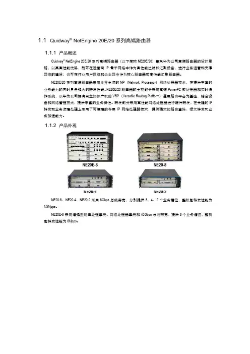
1.1 Quidway® NetEngine 20E/20系列高端路由器1.1.1 产品概述Quidway® NetEngine 20E/20系列高端路由器(以下简称NE20E/20)秉承华为公司高端路由器的设计思路,以其高性能优势,既可在运营商IP骨干网络中作为高性能边缘和汇聚设备,进行业务运营和支撑网络的建设;也可在行业用户网络和企业网中作为核心路由器或高性能汇聚路由器。
NE20E/20系列高端路由器采用业界主流的NP(Network Processor)网络处理器技术,在提供丰富的业务能力的同时具备强大的转发性能。
NE20E/20路由器的主控部分采用高速PowerPC微处理器和实时操作系统,以华为公司拥有自主知识产权的VRP(Versatile Routing Platform)通用路由平台为基础,结合设备和网络管理技术,提供丰富的业务特性。
转发部分采用高性能网络处理器进行硬件转发,在关键的IP 转发和业务流程处理上采用了可编程的专用IP网络处理器技术,提供强大的路由查找、报文转发和业务加速能力。
1.1.2 产品外观NE20-8、NE20-4、NE20-2采用8Gbps总线带宽,分别提供8、4、2个业务槽位,整机包转发性能为4.5Mpps。
NE20E-8采用增强型路由处理单元、网络处理器单元和40Gbps总线带宽,提供8个业务槽位,整机包转发性能为6Mpps。
1.1.3 产品特点●基于第五代路由器的理念进行设计NE20E/20采用业界高性能网络处理器实现高速接口报文线速转发,有机地结合软件的灵活性和硬件的高性能。
NE20E-8性能可达到6Mpps,NE20-8、NE20-4、NE20-2性能可达4.5Mpps。
NE20E/20采用高速接口转发与控制平面分离的技术,高速接口的转发引擎使用了高性能网络处理器,提高了设备的转发性能、控制能力、可靠性和安全性。
●丰富的高密接口和强大接入能力NE20E/20支持丰富的高密的接口:1/2/4 155M POS 、2/4/8 FE、1/2 GE、16E1/T1、单端口155M CPOS、1/2/4 155M ATM高速接口线速转发,4 SA、1/2 52M HSSI、单端口E3/CE3、4CE1/CT1、8CE1/CT1、单端口ATM E3接口等各种业务接口灵活接入。

APT60DQ120SGDatasheet Ultrafast Soft Recovery Rectifier DiodeFinalApril 2018Contents1Revision History (1)1.1Revision A (1)2Product Overview (2)2.1Benefits (2)2.2Applications (2)3Electrical Specifications (3)3.1Absolute Maximum Ratings (3)3.2Electrical Performance (3)3.3Dynamic Characteristics (4)3.4Typical Performance Curves (4)3.5Reverse Recovery Overview (6)4Package Specification (7)4.1Package Outline Drawing (7)1Revision HistoryThe revision history describes the changes that were implemented in the document. The changes arelisted by revision, starting with the most current publication.1.1Revision ARevision A was published in April 2018. It is the first publication of this document.2Product OverviewFeaturesThe following are key features of the APT60DQ120SG device:Ultrafast recovery timesSoft recovery characteristicsLow forward voltageLow leakage currentAvalanche energy ratedRoHS compliant2.1BenefitsThe following are benefits of the APT60DQ120SG device:Higher switching frequencyLow switching lossesLow noise (EMI) switchingHigher reliability systemsIncreased system power density2.2ApplicationsThe APT60DQ120SG device is designed for the following applications: Power Factor Correction (PFC)Anti-parallel diodeSwitch-mode power supplyInverters/convertersMotor controllersFreewheeling diodeSwitch-mode power supplyInverters/convertersSnubber/clamp diode3Electrical SpecificationsThis section shows the electrical specifications for the APT60DQ120SG device.3.1Absolute Maximum RatingsThe following table shows the absolute maximum ratings for the APT60DQ120SG device.All ratings: T = 25 °C unless otherwise specified.CTable 1 • Absolute Maximum RatingsSymbol Parameter Ratings UnitV R Maximum DC reverse voltage1200VV RRM Maximum peak repetitive reverse voltage1200V RWM Maximum working peak reverse voltage1200I F(AV)Maximum average forward current (T = 103 °C, duty cycle = 0.5)C60AI F(RMS)RMS forward current87I FSM Non-repetitive forward surge current (T = 45 °C, 8.3 ms)J540E AVL Avalanche energy (1 A, 40 mH)20mJT , TJ STG Operating and storage temperature range–55 to 175°CT L Lead temperature for 10 seconds300The following table shows the thermal and mechanical characteristics of the APT60DQ120SG device.Table 2 • Thermal and Mechanical CharacteristicsSymbol Characteristic Min Typ Max UnitRθJC Junction-to-case thermal resistance0.40°C/WW T Package weight0.14oz4.0g 3.2Electrical PerformanceThe following table shows the static characteristics of the APT60DQ120SG device.Table 3 • Static CharacteristicsSymbol Characteristic Test Conditions Min Typ Max UnitV F Forward Voltage I = 60 AF 2.8 3.3VI = 120 AF 3.35I = 60 A, T = 125 °CF J 2.11I RM Maximum reverse leakage current V = 1200 VR100μAV = 1200 V, T = 125 °CR J500C J Junction capacitance V = 200 VR37pF3.3Dynamic CharacteristicsThe following table shows the dynamic characteristics of the APT60DQ120SG device.Table 4 • Dynamic CharacteristicsSymbol Characteristic Test ConditionsMin Typ Max Unit t rrReverse recovery timeI = 1 A, di /dt = –100 A/µs F F V = 30 V R T = 25 °CJ30nst rr Reverse recovery time I = 60 A, di /dt = –200 A/µs F F V = 800 V R T = 25 °CC 320 Q rr Reverse recovery change 630 nC I RRM Maximum reverse recovery current 5 A t rr Reverse recovery time I = 60 A, di /dt = –200 A/µs F F V = 800 V R T = 125 °CC 420 ns Q rr Reverse recovery charge 2810 nC I RRM Maximum reverse recovery current 12 A t rr Reverse recovery time I = 60 A, di /dt = –1000 A/µs F F V = 800 V R T = 125 °CC 190 ns Q rr Reverse recovery change 4415 nC I RRMMaximum reverse recovery current38A3.4Typical Performance CurvesThis section shows the typical performance curves for the APT60DQ120SG device.Figure 1 • Maximum Transient Thermal ImpedanceFigure 2 • Forward Current vs. Forward Voltage Figure 3 • trr vs. Current Rate of ChangeFigure 2 • Forward Current vs. Forward Voltage Figure 3 • trr vs. Current Rate of ChangeFigure 4 • Qrr vs. Current Rate of Change Figure 5 • IRRM vs. Current Rate of ChangeFigure 6 • Dynamic Parameters vs. Junction TemperatureFigure 7 • Maximum Average Forward Current vs. Case TemperatureFigure 8 • Junction Capacitance vs. Reverse Voltage1. 2. 3. 4. 5.Figure 8 • Junction Capacitance vs. Reverse Voltage3.5Reverse Recovery OverviewThe following illustration shows the reverse recovery testing and measurement information for the APT60DQ120SG device.Figure 9 • Diode Reverse Recovery Waveform and DefinitionsI —Forward conduction current.F di /dt—Rate of diode current change through zero crossing.F I —Maximum reverse recovery current.RRM t —Reverse recovery time, measured from zero crossing where diode current goes from positive to rr negative, to the point at which the straight line through I and 0.25 × I passes through zero.RRM RRM Q —Area under the curve defined by I and t .rr RRM rr4Package SpecificationThis section outlines the package specification for the APT60DQ120SG device.4.1Package Outline DrawingThis section details the D PAK package drawing of the APT60DQ120SG device. Dimensions are in3millimeters and (inches).Figure 10 • Package Outline DrawingMicrosemi Corporate HeadquartersOne Enterprise, Aliso Viejo,CA 92656 USAWithin the USA: +1 (800) 713-4113Outside the USA: +1 (949) 380-6100Fax: +1 (949) 215-4996Email:***************************© 2018 Microsemi Corporation. All rights reserved. Microsemi and the Microsemi logo are trademarks of Microsemi Corporation. All other trademarks and service marks are the property of their respective owners.Microsemi makes no warranty, representation, or guarantee regarding the information contained herein or the suitability of its products and services for any particular purpose, nor does Microsemi assume any liability whatsoever arising out of the application or use of any product or circuit. The products sold hereunder and any other products sold by Microsemi have been subject to limited testing and should not be used in conjunction with mission-critical equipment or applications. Any performance specifications are believed to be reliable but are not verified, and Buyer must conduct and complete all performance and other testing of the products, alone and together with, or installed in, any end-products. Buyer shall not rely on any data and performance specifications or parameters provided by Microsemi. It is the Buyer's responsibility to independently determine suitability of any products and to test and verify the same. The information provided by Microsemi hereunder is provided "as is, where is" and with all faults, and the entire risk associated with such information is entirely with the Buyer. Microsemi does not grant, explicitly or implicitly, to any party any patent rights, licenses, or any other IP rights, whether with regard to such information itself or anything described by such information. Information provided in this document is proprietary to Microsemi, and Microsemi reserves the right to make any changes to the information in this document or to any products and services at any time without notice.Microsemi Corporation (Nasdaq: MSCC) offers a comprehensive portfolio of semiconductor and system solutions for aerospace & defense, communications, data center and industrial markets. Products include high-performance and radiation-hardened analog mixed-signal integrated circuits, FPGAs, SoCs and ASICs; power management products; timing and synchronization devices and precise time solutions, setting the world's standard for time; voice processing devices; RF solutions; discrete components; enterprise storage and communication solutions; security technologies and scalable anti-tamper products; Ethernet solutions; Power-over-Ethernet ICs and midspans; as well as custom design capabilities and services. Microsemi is headquartered in Aliso Viejo, California, and has approximately 4,800 employees globally. Learn more at .053-4250。

英飞拓产品型号英飞拓产品型号渠道产品,价格优惠,不满意可退货 150********2.1 固定摄像机-PALV5101-A50142 ⼀体化摄像机2.3 因定半球摄像机2.4 V1700A系列快球2.5 V1750A系列充氮快球2.6 V1700S系列内置单模光端机的快球2.7 V1900A系列快球2.8⼀体化云台摄像机2.9恒速球形护罩/云台2.10快球零部件1.模拟监控前端产品2.1 固定摄像机V5101-A2014 V5101-A3014 V5101-A5014 V5101-A2019 V5101-A3019 V5102-A2014 V5102⽇夜型因定摄像机V5102-A3014 V5102-A5014V5102-A3019 V5102-A2019V5103宽动态彩⾊固定摄像机V5103-A3014V1025-1H⾼解析度彩⾊摄像机V1025-1HV1026-1⾼解析度⽇夜转换型摄像机V1026-1V1027-1 1/2英⼨宽动态⾼灵敏度低照度彩⾊摄像机V1027-1V1033-1宽动态⽇夜转换型摄像机V1033-12.2⼀体化摄像机PALV1224⼀体化彩⾊摄像机V1224-22A14V1244⼀体化⽇夜转换摄像机V1244-23A14 V1244-26A14 V5411-A2014ST V5411-A2014SU V5411-A2014SV 2.3固定半球摄像机PALV5411-A2014SW V5411-A2014SX V5411-A2014SYV5411-A2014SZ480线⼿动变焦⾃动光圈镜头V5411-A2014 SBV5411-A2014 SDV5411-A2014SE V5411-A2014SC V5411-A2014SF520线固定焦距镜头V5411-A3014ST V5411-A3014SU V5411-A3014SV V5411-A3014SW V5411-A3014SX V5411-A3014SY V5411-A3014SZ520线⼿动变焦⾃动光圈镜头V5411-A3014SB V5411-A3014SD V5411-A3014SE V5411-A3014SCV5512室内⽇夜型因定半球摄像机V5411-A3014SF V5512-A2014SB V5512-A2014SE520线⼿动变焦⾃动光圈镜头V5512-A3014SB V5512-A3014SEV5413室内宽动态彩⾊固定半球摄像机V5512-A3014SB V5413-A3024SB V5413-A3024SE2.3固定半球摄像机PALV5411-A2014ST V5411-A2014SU V5411-A2014SV V5411-A2014SW V5411-A2014SXV5411-A2014SY480线⼿动变焦⾃动光圈镜头V5411-A2014SZ V5411-A2014SB V5411-A2014SD V5411-A2014SE V5411-A2014SC V5411-A2014SF520线固定焦距镜头V5411-A3014ST V5411-A3014SU V5411-A3014SV V5411-A3014SW V5411-A3014SZ V5411-A3014SY V5411-A3014SX520线⼿动变焦⾃动光圈镜头V5411-A3014SB V5411-A3014SD V5411-A3014SE V5411-A3014SCV5512室内⽇夜型因定半球摄像机V5411-A3014SF V5512-A2014SB520线⼿动变焦⾃动光圈镜头V5512-A2014SE V5512-A3014SB V5512-A3014SB V5512-A3014SEV5413室内宽动态彩⾊固定半球摄像机V5413-A3024SBV1700A系列快球PAL室内吸顶装快球V1725A-C1C2C6 V1726A-C1C2C6 V1727A-C1C2C6 V1728A-C1C2C6 V1724A-C1C2C6 V1729A-C1C2C6 V1723A-C1C2C6室内⽀架装快球V1725A-C1C2B6 V1726A-C1C2B6 V1727A-C1C2B6 V1728A-C1C2B6 V1724A-C1C2B6 V1729A-C1C2B6 V1723A-C1C2B6室外吸顶装快球V1745A-C1C2C6 V1746A-C1C2C6 V1747A-C1C2C6 V1748A-C1C2C6 V1744A-C1C2C6 V1749A-C1C2C6 V1743A-C1C2C6室外⽀架装快球V1745A-C1C2B6 V1746A-C1C2B6 V1747A-C1C2B6 V1748A-C1C2B6 V1744A-C1C2B6 V1749A-C1C2B6 V1743A-C1C2B62.5 V1750A 系列充氮快球-PAL室内充氮吊装快球V1757A-C1C3B6 V1758A-C1C3B6 V1759A-C1C3B6 V1753A-C1C3B6 V1791室内内置单模光端机吸顶装快球V1725S-C1C2C6 V1726S-C1C2C6 V1727S-C1C2C6 V1728S-C1C2C6 V1729S-C1C2C6 V1723S-C1C2C6室内内置单模光端机⽀架装快球V1725S-C1C2B6V1726S-C1C2B6V1727S-C1C2B6 V1728S-C1C2B6 V1729S-C1C2B6 V1723S-C1C2B6室外内置单模光端机吸顶装快球V1745S-C1C2C6 V1746S-C1C2C6 V1747S-C1C2C6 V1748S-C1C2C6 V1743S-C1C2C6 V17243S-C1C2C6室外内置单模光端机⽀架装快球V1745S-C1C2B6 V1746S-C1C2B6 V1747S-C1C2B6 V1748S-C1C2B6 V1749S-C1C2B6 V1724S-C1C2B62.7V1900A系列快球PAL室内吸顶装快球V1901A-C1C2C6 V1902A-C1C2C6 V1903A-C1C2C6 V1904A-C1C2C6 V1906A-C1C2C6室内⽀架装快球V1901A-C1C2B6 V1902A-C1C2B6 V1903A-C1C2B6 V1904A-C1C2B6 V1906A-C1C2B6室外吸顶装快球V1911A-C1C2C6 V1912A-C1C2C6 V1913A-C1C2C6 V1914A-C1C2C6 V1916A-C1C2B6 V1917A-C1C2B6室外⽀架装快球V1911A-C1C2B6 V1912A-C1C2B6 V1913A-C1C2B6 V1914A-C1C2B6 V1916A-C1C2B6 V1917A-C1C2B62.8 ⼀体化云台摄像机V1492-18A15 V1492-23A15 V1492-26A15 V1492-35A15 V1492-36A15 V1492-18A16 V1492-23A16 V1492-26A16 V1492-35A16 V1492-36A16 V1492-18A17 V1492-23A17 V1492-26A17 V1492-35A17 V1492-36A17 V1492-18A18 V1492-23A18 V1492-26A18 V1492-35A18V1492-36A18⼀体化云台⽀架(适⽤于V1492、V1493)V1662-W1 V1662-S1 V1662-C1 V1662-DV1493中型⾼速云台V1493-D16V7A15 V1493-DP16V7A15 V1493-A15 V1493-D16V7A16 V1493-DP16V7A16 V1493-A16 V1493-D16V7A17 V1493-DP16V7A17 V1493-A17 V1493-D16V7A18 V1493-DP16V7A18 V1493-A18V1631隔爆云台摄像机V1631-23A19 V1631-25A19防爆护罩V1421-15SHB6-2V1421-15SHB8-2V1421-15A6-2V1421-15A8-2隔爆云台⽀架V1664-W V1664-C V1664-S V1665-W12.9恒速球形护罩/云台V1682 系列室内/室外恒速球形云台V1682-C2B-9HBPV1682-C2B-9HBP2.10 快球零部件V1761 V1761L V1762 V1763 V1764 V1764A V1764B V1765 V1765A V1766适⽤V1750A系列充氮快球V1761S V1762S V1763S球芯V1700N系列⽹络快球球芯(PAL)(坜另配视频缟码卡)V1825N-C16 V1826N-C16 V1827N-C16 V1828N-C16 V1829N-C16 V1825N-C15 V1826N-C15 V1827N-C15V1828N-C16 V1829N-C16V1700A系列快球球芯(PAL)V1825A-C16 V1826A-C16 V1827A-C16 V1828A-C16 V1829A-C16 V1825N-C15 V1826N-C15 V1827N-C15V1828N-C16 V1829N-C16V1750A系列充氮快球球芯(PAL)V1825AP-C16 V1826AP-C16 V1827AP-C16 V1828AP-C16 V1829AP-C16 V1825AP-C15 V1826AP-C15 V1827AP-C15 V1828AP-C15 V1829AP-C15V1700S系列光端机快球球芯(PAL)V1825AF-C16 V1826 AF-C16 V1827 AF-C16 V1828 AF-C16 V1829 AF-C16 V1825AF-C15 V1826 AF-C15 V1827 AF-C15 V1828 AF-C15 V1829 AF-C15V1900A系列快球球芯(PAL)V1901A-C16 V1902A-C16 V1903A-C16 V1904A-C16 V1905A-C16 球罩快球下罩(不带法兰)V1840-C2 V1840-S2 V1840-C3 V1840-S3室内吸顶装配罩下罩(带法兰)V1840-C2C V1840-S2C V1840-C3C V1840-S3C室内⽀架装配罩下罩(带法兰)V1840-C2B V1840-S2B V1840-C3B V1840-S3B室外⽀架装和吸顶装配罩下罩(带法兰和加热器)V1840-C2O V1840-S2O V1840-C3O V1840-S3O V1840P-C3OV1840P-S3O快球上罩(带法兰)V1850-IC V1850-IB V1850-OC V1850-OB V1850P-OB V1852-IC V1852-IB V1852-OC V1852-OB快球电源板V1860A-C6 V1860N-L6 V1860A-C5 V1860N-L5快球电源V3922-24A-26.键盘及辅助设备6.1 键盘V2100 V2109X V2111X V2110 V2115 V2116X7.3 V2020系列中型矩阵切换/控制器V2020AX-16X4 V2020AX-16X8 V2020AX-16X12 -16X16 V2020AX-16X20 V2020AX-16X24 V2020AX-16X28V2020AX-16X32 V2020AX-32X4 V2020AX-32X8 V2020AX-32X12 V2020AX-32X16 V2020AX-32X20 V2020AX-32X24 V2020AX-32X28 V2020AX-32X32 V2020AX-48X4 V2020AX-48X8V2020AX-48X12 V2020AX-48X16 V2020AX-48X20 V2020AX-48X24 V2020AX-48X28 V2020AX-48X32 V2020AX-64X4 V2020AX-64X8 V2020AX-64X12 V2020AX-64X16 V2020AX-64X20 V2020AX-64X24 V2020AX-64X28 V2020AX-64X32 V2020AX-80X4 V2020AX-80X8 V2020AX-80X12 V2020AX-80X16 V2020AX-80X20 V2020AX-80X24V2020AX-80X28 V2020AX-80X32 V2020AX-96X4 V2020AX-96X8 V2020AX-96X12 V2020AX-96X16 V2020AX-96X20 V2020AX-96X24 V2020AX-96X28 V2020AX-96X32V2020AX-112X4 V2020AX-112X8 V2020AX-112X12 V2020AX-112X16 V2020AX-112X20 V2020AX-112X24V2020AX-112X28 V2020AX-112X32 V2020AX-128X4 V2020AX-128X8 V2020AX-128X12 V2020AX-128X16V2020AX-128X20 V2020AX-128X24 V2020AX-128X28 V2020AX-128X32 V2020AX-144X4 V2020AX-144X8V2020AX-144X12 V2020AX-144X16 V2020AX-144X20 V2020AX-144X24 V2020AX-144X28 V2020AX-144X32V2020AX-160X4 V2020AX-160X8 V2020AX-160X12 V2020AX-160X16 V2020AX-160X20 V2020AX-160X24V2020AX-160X28 V2020AX-160X32 V2020AX-176X4 V2020AX-176X8 V2020AX-176X12 V2020AX-176X16V2020AX-176X20 V2020AX-176X24 V2020AX-176X28 V2020AX-176X32 V2020AX-192X4 V2020AX-192X8V2020AX-192X12 V2020AX-192X16 V2020AX-192X20 V2020AX-192X24 V2020AX-192X28 V2020AX-192X32 V2020AX-208X4 V2020AX-208X8 V2020AX-208X12 V2020AX-208X16 V2020AX-208X20 V2020AX-208X24V2020AX-208X28 V2020AX-208X32 V2020AX-224X4 V2020AX-224X8 V2020AX-224X12 V2020AX-224X16V2020AX-224X20 V2020AX-224X24 V2020AX-224X28 V2020AX-224X32 V2020AX-240X4 V2020AX-240X8 V2020AX-240X12 V2020AX-240X16 V2020AX-240X20 V2020AX-240X24 V2020AX-240X28 V2020AX-240X32V2040AX-16X4 V2040AX-16X8 V2040AX-16X12 V2040AX-16X16 V2040AX-16X20 V2040AX-16X24V2040AX-16X28 V2040AX-16X32 V2040AX-32X4 V2040AX-32X8 V2040AX-32X12 V2040AX-32X16V2040AX-32X20 V2040AX-32X24 V2040AX-32X28 V2040AX-32X32 V2040AX-48X4 V2040AX-48X8V2040AX-48X12 V2040AX-48X16 V2040AX-48X20 V2040AX-48X24 V2040AX-48X28 V2040AX-48X32V2040AX-64X4 V2040AX-64X8 V2040AX-64X12 V2040AX-64X16 V2040AX-64X20 V2040AX-64X24 V2040AX-64X28 V2040AX-64X32 V2040AX-80X4 V2040AX-80X8 V2040AX-80X12 V2040AX-80X16 V2040AX-80X20V2040AX-80X24 V2040AX-80X28 V2040AX-80X32V2040AX-96X4 V2040AX-96X8 V2040AX-96X12 V2040AX-96X16 V2040AX-96X20 V2040AX-96X24 V2040AX-96X28 V2040AX-96X32 V2040AX-112X4 V2040AX-112X8 V2040AX-112X12 V2040AX-112X16 V2040AX-112X20 V2040AX-112X24 V2040AX-112X28V2040AX-112X32 V2040AX-128X4 V2040AX-128X8 V2040AX-128X12 V2040AX-128X16V2040AX-128X20 V2040AX-128X24 V2040AX-128X28 V2040AX-128X32 V2040AX-144X4V2040AX-144X8 V2040AX-144X12 V2040AX-144X16 V2040AX-144X20 V2040AX-144X24V2040AX-144X28 V2040AX-144X32 V2040AX-160X4 V2040AX-160X8 V2040AX-160X12V2040AX-160X16 V2040AX-160X20 V2040AX-160X24 V2040AX-160X28 V2040AX-160X32 V2040AX-176X4V2040AX-176X8 V2040AX-176X12 V2040AX-176X16 V2040AX-176X20V2040AX-176X24 V2040AX-176X28 V2040AX-176X32 V2040AX-192X4 V2040AX-192X8V2040AX-192X12 V2040AX-192X16 V2040AX-192X20 V2040AX-192X24 V2040AX-192X28V2040AX-192X32V2040AX-208X4 V2040AX-208X8 V2040AX-208X12 V2040AX-208X16 V2040AX-208X20 V2040AX-208X24V2040AX-208X28 V2040AX-208X32 V2040AX-224X4 V2040AX-224X8 V2040AX-224X12 V2040AX-224X16V2040AX-224X20 V2040AX-224X24 V2040AX-224X28 V2040AX-224X32 V2040AX-240X4 V2040AX-240X8V2040AX-240X12 V2040AX-240X16 V2040AX-240X20 V2040AX-240X24 V2040AX-240X28 V2040AX-240X32V2040AX-256X4V2040AX-256X8 V2040AX-256X12 V2040AX-256X16 V2040AX-256X20 V2040AX-256X24V2040AX-256X28 V2040AX-256X32A2011X-16X5 A2011X-32X5 A2020X-16X4 A2020X-16X8 A2020X-16X12 A2020X-16X16 A2020X-16X20 A2020X-16X24 A2020X-16X28 A2020X-16X32 A2020X-32X4 A2020X-32X8 A2020X-32X12 A2020X-32X16 A2020X-32X20 A2020X-32X24 A2020X-32X28A2020X-32X32 A2020X-48X4 A2020X-48X8 A2020X-48X12 A2020X-48X16 A2020X-48X20A2020X-48X24 A2020X-48X28 A2020X-48X32 A2020X-64X4 A2020X-64X8 A2020X-64X12A2020X-64X16 A2020X-64X20 A2020X-64X24 A2020X-64X28 A2020X-64X32 A2020X-80X4A2020X-80X8 A2020X-80X12 A2020X-80X16 A2020X-80X20 A2020X-80X24 A2020X-80X28A2020X-80X32 A2020X-96X4 A2020X-96X8 A2020X-96X12 A2020X-96X16 A2020X-96X20 A2020X-96X24 A2020X-96X28 A2020X-96X32 A2020X-112X4A2020X-112X8 A2020X-112X12 A2020X-112X16 A2020X-112X20 A2020X-112X24A2020X-112X28 A2020X-112X32 A2020X-128X4 A2020X-128X8 A2020X-128X12 A2020X-128X16 A2020X-128X20 A2020X-128X24 A2020X-128X28 A2020X-128X32A2020X-144X4 A2020X-144X8 A2020X-144X12 A2020X-144X16 A2020X-144X20 A2020X-144X24 A2020X-144X28 A2020X-144X32 A2020X-160X4 A2020X-160X8 A2020X-160X12 A2020X-160X16 A2020X-160X20 A2020X-160X24 A2020X-160X28A2020X-160X32 A2020X-176X4 A2020X-176X8 A2020X-176X12 A2020X-176X16 A2020X-176X20A2020X-176X24 A2020X-176X28 A2020X-176X32 A2020X-192X4 A2020X-192X8 A2020X-192X12 A2020X-192X16 A2020X-192X20 A2020X-192X24 A2020X-192X28 A2020X-192X32 A2020X-208X4 A2020X-208X8。
BLC9G27LS-151AVPower LDMOS transistorRev. 3 — 24 May 2017Product data sheet 1. Product profile1.1General description150W LDMOS packaged asymmetrical Doherty power transistor for base stationapplications at frequencies from 2496MHz to 2690MHz.Table 1.Typical performanceTypical RF performance at T case = 25 ︒C in the Doherty demo board.Test signal f V DS P L(AV)G pηD ACPR(MHz)(V)(W)(dB)(%)(dBc)1-carrier W-CDMA2496 to 26902828.215.548-30 [1][1]Test signal: 3GPP test model 1; 1 to 64 DPCH; PAR=7.2dB at 0.01% probability on CCDF.1.2Features and benefits⏹Excellent ruggedness⏹High efficiency⏹Low thermal resistance providing excellent thermal stability⏹Decoupling leads to enable improved video bandwidth⏹Lower output capacitance for improved performance in Doherty applications⏹Designed for low memory effects providing excellent pre-distortability⏹Internally matched for ease of use⏹Integrated ESD protection⏹Compliant to Directive 2002/95/EC, regarding Restriction of Hazardous Substances(RoHS)1.3Applications⏹RF power amplifier for LTE base stations and multi carrier applications in the2496MHz to 2690MHz frequency range2. Pinning informationTable 2.Pinning[1]Connected to flange.3. Ordering informationTable 3.Ordering informationType number PackageName Description Version BLC9G27LS-151AV-air cavity plastic earless flanged package; 6 leads SOT1275-14. Limiting valuesTable 4.Limiting valuesIn accordance with the Absolute Maximum Rating System (IEC 60134).Symbol Parameter Conditions Min Max UnitV DS drain-source voltage-65VV GS gate-source voltage-5+13VT stg storage temperature-65+150︒CT j junction temperature[1]-225︒C[1]Continuous use at maximum temperature will affect the reliability, for details refer to the online MTFcalculator.5. Thermal characteristicsTable 5.Thermal characteristicsSymbol Parameter Conditions Typ UnitR th(j-case)thermal resistance from junction to case T case=80︒C; I Dq=280mA;V GS(amp) peak = 0.85 VP L = 28.2 W0.314K/WP L = 44.7 W0.270K/W6. CharacteristicsTable 6.DC characteristicsT j = 25 ︒C unless otherwise specified.Symbol Parameter Conditions Min Typ Max UnitMain deviceV(BR)DSS drain-source breakdown voltage V GS=0V;I D=0.5mA65--VV GS(th)gate-source threshold voltage V DS=10 V; I D=50mA 1.52 2.5VV GSq gate-source quiescent voltage V DS=28 V; I D=300mA 1.75 2.3 2.85VI DSS drain leakage current V GS=0V;V DS=32V-- 1.4μA-10.9-AI DSX drain cut-off current V GS=V GS(th)+3.75 V;V DS=10VI GSS gate leakage current V GS=11V;V DS=0V--140nAg fs forward transconductance V DS=10V;I D=50 mA-0.53-S-285460mΩR DS(on)drain-source on-state resistance V GS=V GS(th) + 3.75V;I D=1.75APeak deviceV(BR)DSS drain-source breakdown voltage V GS=0V;I D=1.1mA65--VV GS(th)gate-source threshold voltage V DS=10 V; I D=110mA 1.52 2.5VV GSq gate-source quiescent voltage V DS=28 V; I D=660mA 1.65 2.2 2.75VI DSS drain leakage current V GS=0V;V DS=32V-- 1.4μA-23.8-AI DSX drain cut-off current V GS=V GS(th)+3.75 V;V DS=10VI GSS gate leakage current V GS=11V;V DS=0V--140nAg fs forward transconductance V DS=10V;I D=110mA- 1.16-S-130215mΩR DS(on)drain-source on-state resistance V GS=V GS(th) + 3.75V;I D=3.85ATable 7.RF characteristicsTest signal: 1-carrier W-CDMA; PAR = 7.2 dB at 0.01% probability on the CCDF;3GPP test model1; 1 to 64 DPCH; f1=2496MHz; f2=2690MHz; RF performance at V DS=28V;I Dq=280mA (main); V GS(amp)peak=0.8V; T case=25︒C; unless otherwise specified; in anasymmetrical Doherty production test circuit at frequencies from 2496MHz to 2690 MHz.Symbol Parameter Conditions Min Typ Max UnitG p power gain P L(AV)=28W14.415.6-dBRL in input return loss P L(AV)=28W--11-7dBηD drain efficiency P L(AV)=28W4146-%ACPR adjacent channel power ratio P L(AV)=28W--30-25dBcTable 8.RF characteristicsTest signal: pulsed CW; t p=100μs; δ=10%; f=2690MHz; RF performance at V DS = 28 V;I Dq=280mA(main); V GS(amp)peak=0.8V; T case = 25 ︒C; unless otherwise specified; tested in anasymmetrical Doherty production test circuit at frequencies from 2496MHz to 2690MHz.Symbol Parameter Conditions Min Typ Max UnitP L(3dB)output power at 3 dB gain compression135155-W7. Test information7.1Ruggedness in Doherty operationThe BLC9G27LS-151AV is capable of withstanding a load mismatch corresponding to aVSWR=10: 1 through all phases under the following conditions: V DS=28V;I Dq=200mA (main); V GS(amp)peak=0.85V; P L=50 W(1-carrier W-CDMA);f=2496MHz.7.2Impedance informationTable 9.Typical impedance of main deviceMeasured load-pull data of main device; I Dq = 300 mA (main); V DS = 28 V.f Z S [1]Z L [1]P L [2]ηD [2]G p [2](MHz)(Ω)(Ω)(W)(%)(dB)Maximum power load2496 6.2 - j7.7 3.3 - j7.771.555.818.12600 6.1- j5.9 3.3 - j7.771.355.718.52690 3.6 - j5.4 3.3 - j7.766.954.919.1Maximum drain efficiency load2496 6.2 - j7.7 6.4 - j5.752.863.520.32600 6.1- j5.9 6.0 - j5.952.164.321.12690 3.6 - j5.4 5.0 - j5.048.561.821.5[1]Z S and Z L defined in Figure1.[2]at 3 dB gain compression.Table 10.Typical impedance of peak deviceMeasured load-pull data of peak device; I Dq = 600 mA (peak); V DS = 28 V.f Z S [1]Z L [1]P L [2]ηD [2]G p [2](MHz)(Ω)(Ω)(W)(%)(dB)Maximum power load24967.2 - j8.6 4.1- j9.1146.958.217.626008.0- j6.3 4.1- j9.1141.156.017.92690 6.0 - j2.8 5.0 - j10.0137.355.718.3Maximum drain efficiency load24967.2 - j8.6 5.8- j6.2115.565.319.526008.0- j6.3 5.4 - j5.5103.264.220.22690 6.0 - j2.8 4.8 - j5.998.562.820.6[1]Z S and Z L defined in Figure1.[2]at 3 dB gain compression.7.3Recommended impedances for Doherty designTable 11.Typical impedance of main device at 1:1 loadMeasured load-pull data of main device; I Dq = 300 mA (main); V DS = 28 V.f Z S [1]Z L [1]P L [2]ηD [3]G p [3](MHz)(Ω)(Ω)(dBm)(%)(dB) 2496 6.2 - j7.7 3.7 - j7.048.141.518.5 2600 6.1- j5.9 3.7 - j7.148.042.018.7 2690 3.6 - j5.4 3.7 - j7.248.042.019.3[1]Z S and Z L defined in Figure1.[2]at 3 dB gain compression.[3]at P L(AV)=44.5 dBm.Table 12.Typical impedance of main device at 1:2.5 loadMeasured load-pull data of main device; I Dq = 300 mA (main); V DS = 28 V.f Z S [1]Z L [1]P L [2]ηD [3]G p [3](MHz)(Ω)(Ω)(dBm)(%)(dB) 2496 6.2 - j7.7 6.8 - j12.946.25520.7 2600 6.1- j5.9 6.0 - j14.146.75421.3 2690 3.6 - j5.4 5.5- j13.745.95321.8[1]Z S and Z L defined in Figure1.[2]at 3 dB gain compression.[3]at P L(AV)=44.5 dBm.7.4VBW in Doherty operationThe BLC9G27LS-151AV shows 100MHz (typical) video bandwidth in Doherty demo board in 2600MHz at V DS=28V;I Dq=250 mA and V GS(amp)peak=0.8V.7.5Test circuit[1]American Technical Ceramics type 600F or capacitor of same quality [2]Murata or capacitor of same qualityTable 13.List of components See Figure 2 for component ponentDescriptionValue RemarksC1, C2, C3, C4, C6, C7, C8multilayer ceramic chip capacitor 9.1pF [1]C5multilayer ceramic chip capacitor 4.3pF [1]C9, C11multilayer ceramic chip capacitor 1 μF, 50V [2]C10, C12, C13, C14, C15, C16multilayer ceramic chip capacitor 10 μF, 50V [2]C17, C18electrolytic capacitor 1000 μF, 100V R1resistor 51 ΩSMD 0805R2. R3resistor9.1 ΩSMD 08057.6Graphical data 7.6.1Pulsed CW7.6.21-Carrier W-CDMA7.6.32-Tone VBW8. Package outlineFig 9.Package outline SOT1275-19. Handling informationTable 14.ESD sensitivityESD model ClassCharged Device Model (CDM); According to ANSI/ESDA/JEDEC standard JS-002C2A [1]Human Body Model (HBM); According to ANSI/ESDA/JEDEC standard JS-001 2 [2][1]CDM classification C2A is granted to any part that passes after exposure to an ESD pulse of 500V, but failsafter exposure to an ESD pulse of 750V.[2]HBM classification 2 is granted to any part that passes after exposure to an ESD pulse of 2000V, but failsafter exposure to an ESD pulse of 4000V.10. AbbreviationsTable 15.AbbreviationsAcronym Description3GPP3rd Generation Partnership ProjectCCDF Complementary Cumulative Distribution FunctionCW Continuous WaveDPCH Dedicated Physical CHannelESD ElectroStatic DischargeLDMOS Laterally Diffused Metal-Oxide SemiconductorLTE Long Term EvolutionMTF Median Time to FailurePAR Peak-to-Average RatioSMD Surface Mounted DeviceVBW Video BandWidthVSWR Voltage Standing Wave RatioW-CDMA Wideband Code Division Multiple Access11. Revision historyTable 16.Revision historyDocument ID Release date Data sheet status Change notice SupersedesBLC9G27LS-151AV v.320170524Product data sheet-BLC9G27LS-151AV v.2 Modifications:•Table2 on page2: change simplified outline•Table3 on page2: change version to SOT1275-1•Figure9 on page10: change package outline drawing to SOT1275-1BLC9G27LS-151AV v.220161202Product data sheet-BLC9G27LS-151AV v.1 BLC9G27LS-151AV v.120160226Product data sheet--12. Legal information12.1 Data sheet status[1]Please consult the most recently issued document before initiating or completing a design.[2]The term ‘short data sheet’ is explained in section “Definitions”.[3]The product status of device(s) described in this document may have changed since this document was published and may differ in case of multiple devices. The latest product statusinformation is available on the Internet at URL .12.2 DefinitionsDraft — The document is a draft version only. The content is still under internal review and subject to formal approval, which may result in modifications or additions. Ampleon does not give any representations or warranties as to the accuracy or completeness of information included herein and shall have no liability for the consequences of use of such information.Short data sheet — A short data sheet is an extract from a full data sheet with the same product type number(s) and title. A short data sheet is intended for quick reference only and should not be relied upon to contain detailed and full information. For detailed and full information see the relevant full data sheet, which is available on request via the local Ampleon sales office. In case of any inconsistency or conflict with the short data sheet, the full data sheet shall prevail.Product specification — The information and data provided in a Product data sheet shall define the specification of the product as agreed between Ampleon and its customer, unless Ampleon and customer have explicitly agreed otherwise in writing. In no event however, shall an agreement be valid in which the Ampleon product is deemed to offer functions and qualities beyond those described in the Product data sheet.12.3 DisclaimersLimited warranty and liability — Information in this document is believed to be accurate and reliable. However, Ampleon does not give any representations or warranties, expressed or implied, as to the accuracy or completeness of such information and shall have no liability for the consequences of use of such information. Ampleon takes no responsibility for the content in this document if provided by an information source outside of Ampleon.In no event shall Ampleon be liable for any indirect, incidental, punitive, special or consequential damages (including - without limitation - lost profits, lost savings, business interruption, costs related to the removal or replacement of any products or rework charges) whether or not such damages are based on tort (including negligence), warranty, breach of contract or any other legal theory.Notwithstanding any damages that customer might incur for any reason whatsoever, Ampleon’s aggregate and cumulative liability towards customer for the products described herein shall be limited in accordance with the Terms and conditions of commercial sale of Ampleon.Right to make changes — Ampleon reserves the right to make changes to information published in this document, including without limitation specifications and product descriptions, at any time and without notice. This document supersedes and replaces all information supplied prior to the publication hereof.Suitability for use — Ampleon products are not designed, authorized or warranted to be suitable for use in life support, life-critical or safety-critical systems or equipment, nor in applications where failure or malfunction of an Ampleon product can reasonably be expected to result in personal injury, death or severe property or environmental damage. Ampleon and its suppliers accept no liability for inclusion and/or use of Ampleon products in such equipment or applications and therefore such inclusion and/or use is at the customer’s own risk.Applications — Applications that are described herein for any of these products are for illustrative purposes only. Ampleon makes no representation or warranty that such applications will be suitable for the specified use without further testing or modification.Customers are responsible for the design and operation of their applications and products using Ampleon products, and Ampleon accepts no liability for any assistance with applications or customer product design. It is customer’s sole responsibility to determine whether the Ampleon product is suitable and fit for the customer’s applications and products planned, as well as for the planned application and use of customer’s third party customer(s). Customers should provide appropriate design and operating safeguards to minimize the risks associated with their applications and products.Ampleon does not accept any liability related to any default, damage, costs or problem which is based on any weakness or default in the customer’s applications or products, or the application or use by customer’s third party customer(s). Customer is responsible for doing all necessary testing for the customer’s applications and products using Ampleon products in order to avoid a default of the applications and the products or of the application or use by customer’s third party customer(s). Ampleon does not accept any liability in this respect.Limiting values — Stress above one or more limiting values (as defined in the Absolute Maximum Ratings System of IEC60134) will cause permanent damage to the device. Limiting values are stress ratings only and (proper) operation of the device at these or any other conditions above those given in the Recommended operating conditions section (if present) or the Characteristics sections of this document is not warranted. Constant or repeated exposure to limiting values will permanently and irreversibly affect the quality and reliability of the device.Terms and conditions of commercial sale — Ampleon products are sold subject to the general terms and conditions of commercial sale, as published at /terms, unless otherwise agreed in a valid written individual agreement. In case an individual agreement is concluded only the terms and conditions of the respective agreement shall apply. Ampleon hereby expressly objects to applying the customer’s general terms and conditions with regard to the purchase of Ampleon products by customer.No offer to sell or license — Nothing in this document may be interpreted or construed as an offer to sell products that is open for acceptance or the grant, conveyance or implication of any license under any copyrights, patents or other industrial or intellectual property rights.Export control — This document as well as the item(s) described herein may be subject to export control regulations. Export might require a prior authorization from competent authorities.Document status[1][2]Product status[3]DefinitionObjective [short] data sheet Development This document contains data from the objective specification for product development. Preliminary [short] data sheet Qualification This document contains data from the preliminary specification.Product [short] data sheet Production This document contains the product specification.Non-automotive qualified products — Unless this data sheet expressly states that this specific Ampleon product is automotive qualified, the product is not suitable for automotive use. It is neither qualified nor tested in accordance with automotive testing or application requirements. Ampleon accepts no liability for inclusion and/or use of non-automotive qualified products in automotive equipment or applications.In the event that customer uses the product for design-in and use in automotive applications to automotive specifications and standards, customer (a) shall use the product without Ampleon’ warranty of the product for such automotive applications, use and specifications, and (b) whenever customer uses the product for automotive applications beyond Ampleon’ specifications such use shall be solely at customer’s own risk, and (c) customer fully indemnifies Ampleon for any liability, damages or failed product claims resulting from customer design and use of the product for automotive applications beyond Ampleon’ standard warranty and Ampleon’ product specifications.Translations — A non-English (translated) version of a document is for reference only. The English version shall prevail in case of any discrepancy between the translated and English versions.12.4 TrademarksNotice: All referenced brands, product names, service names and trademarks are the property of their respective owners.Any reference or use of any ‘NXP’ trademark in this document or in or on the surface of Ampleon products does not result in any claim, liability or entitlement vis-à-vis the owner of this trademark. Ampleon is no longer part of the NXP group of companies and any reference to or use of the ‘NXP’ trademarks will be replaced by reference to or use of Ampleon’s own trademarks.13. Contact informationFor more information, please visit: For sales office addresses, please visit: /sales14. Contents1 Product profile. . . . . . . . . . . . . . . . . . . . . . . . . . 11.1 General description . . . . . . . . . . . . . . . . . . . . . 11.2 Features and benefits. . . . . . . . . . . . . . . . . . . . 11.3 Applications . . . . . . . . . . . . . . . . . . . . . . . . . . . 12 Pinning information. . . . . . . . . . . . . . . . . . . . . . 23 Ordering information. . . . . . . . . . . . . . . . . . . . . 24 Limiting values. . . . . . . . . . . . . . . . . . . . . . . . . . 25 Thermal characteristics . . . . . . . . . . . . . . . . . . 26 Characteristics. . . . . . . . . . . . . . . . . . . . . . . . . . 37 Test information. . . . . . . . . . . . . . . . . . . . . . . . . 47.1 Ruggedness in Doherty operation . . . . . . . . . . 47.2 Impedance information. . . . . . . . . . . . . . . . . . . 47.3 Recommended impedances for Doherty design 57.4 VBW in Doherty operation . . . . . . . . . . . . . . . . 57.5 Test circuit. . . . . . . . . . . . . . . . . . . . . . . . . . . . . 67.6 Graphical data . . . . . . . . . . . . . . . . . . . . . . . . . 77.6.1 Pulsed CW . . . . . . . . . . . . . . . . . . . . . . . . . . . . 77.6.2 1-Carrier W-CDMA . . . . . . . . . . . . . . . . . . . . . . 87.6.3 2-Tone VBW. . . . . . . . . . . . . . . . . . . . . . . . . . . 98 Package outline. . . . . . . . . . . . . . . . . . . . . . . . 109 Handling information. . . . . . . . . . . . . . . . . . . . 1110 Abbreviations. . . . . . . . . . . . . . . . . . . . . . . . . . 1111 Revision history. . . . . . . . . . . . . . . . . . . . . . . . 1212 Legal information. . . . . . . . . . . . . . . . . . . . . . . 1312.1 Data sheet status . . . . . . . . . . . . . . . . . . . . . . 1312.2 Definitions. . . . . . . . . . . . . . . . . . . . . . . . . . . . 1312.3 Disclaimers. . . . . . . . . . . . . . . . . . . . . . . . . . . 1312.4 Trademarks. . . . . . . . . . . . . . . . . . . . . . . . . . . 1413 Contact information. . . . . . . . . . . . . . . . . . . . . 1414 Contents. . . . . . . . . . . . . . . . . . . . . . . . . . . . . . 15Please be aware that important notices concerning this document and the product(s)described herein, have been included in section ‘Legal information’.© Ampleon Netherlands B.V.2017.All rights reserved.For more information, please visit: For sales office addresses, please visit: /sales。
Lenovo Flex System EN2092 1Gb Ethernet Scalable SwitchProduct Guide (withdrawn product)The Lenovo® Flex System™ EN2092 1Gb Ethernet Scalable Switch enables administrators to offer full Layer 2 and 3 switching and routing capability with combined 1 Gb and 10 Gb external ports in a Flex System chassis. Such consolidation simplifies the data center infrastructure and helps reduce the number of discrete devices, management consoles, and management systems while leveraging the 1 Gb Ethernet infrastructure. In addition, the next-generation switch module hardware supports IPv6 Layer 3 frame forwarding protocols. This Scalable Switch delivers cost savings with flexible port mapping and Features on Demand upgrades, efficient traffic management, increased external bandwidth, and strong Ethernet switching price/performance.The following figure shows the switch module.Figure 1. Lenovo Flex System EN2092 1Gb Ethernet Scalable SwitchDid you know?The base switch configuration comes standard with 24x 1 GbE port licenses that can be assigned to internal or external 1 GbE connections or even external SFP+ ports with flexible port mapping. For example, this feature allows customers to trade off one external 1 GbE RJ-45 port for one internal 1 GbE port (or vice versa) or trade off ten 1 GbE ports for one 10 GbE port. Customers then have the flexibility of turning on more ports when you need them using Lenovo's Features on Demand upgrade licensing capabilities that provide “pay as you grow” scalability without the need to buy additional hardware. Delivering advanced virtualization awareness and cloud readiness helps simplify management and automates VM mobility by making the network VM aware with VMready® which works with all the major hypervisors.Click here to check for updatesFigure 2. Front panel of the Flex System EN2092 1Gb Ethernet Scalable SwitchThe front panel contains the following components:20x 1000BASE-T Ethernet external ports for 10/100/1000 Mbps connections to external Ethernet devices.4x SFP+ external ports to attach SFP/SFP+ transceivers for 1 Gb or 10 Gb connections or DAC cables for 10 Gb Ethernet connections.One mini-USB RS-232 console port that provides an additional means to configure the switchFigure 3. Location of the I/O bays in the Flex System chassisThe EN2092 switch can be installed in bays 1, 2, 3, and 4 of the Flex System chassis. A supported adapter card must be installed in a corresponding slot of the compute node. Each adapter can use up to four lanes to connect to the respective I/O module bay. The EN2092 is able to use up to two of the four lanes.In compute nodes that have an integrated dual-port 10 GbE network interface controller (NIC), NIC's ports are routed to bays 1 and 2 with a specialized periscope connector, and the adapter card is not required. However, when needed, the periscope connector can be replaced with the adapter card. In such a case integrated NIC will be disabled.Prior to Networking OS 7.8, with 4-port or 8-port adapters, an optional Upgrade 1 (90Y3562) was required for the switch to allow communications on four ports. With Networking OS 7.8 or later, there is no need to buy additional switch upgrades for 4-port adapters if the total number of port licenses on the switch does not exceed the number of external (upstream network ports) and internal (compute node network ports) connections used.The midplane connections between the adapters that are installed in the compute nodes to the I/O module bays in the chassis are listed in the following table. Half-wide compute nodes support up to two adapters, and full-wide compute nodes support up to four adapters.Table 8. Adapter to I/O bay correspondenceI/O adapter slotin the compute node Port on the adapter Corresponding I/O module bay in the chassisBay 1Bay 2Bay 3Bay 4Slot 1Port 1YesPort 2YesPort 3YesPort 4YesSlot 2Port 1YesPort 2YesPort 3YesPort 4YesSlot 3(full-wide compute nodes only)Port 1YesPort 2Yes Port 3YesPort 4YesSlot 4(full-wide compute nodes only)Port 1YesPort 2Yes Port 3YesPort 4YesThe following table lists the I/O adapters that are supported by the EN2092 1Gb Scalable Switch. 10 GbE adapters operate at 1 GbE speeds when used with this switch.Table 9. Network adaptersDescription Part number Feature code10 Gb Ethernet (10 GbE adapters operate at 1 GbE speeds)Embedded 10Gb Virtual Fabric Adapter (2-port)*None NoneFlex System CN4022 2-port 10Gb Converged Adapter#88Y5920A4K3Flex System CN4052 2-port 10Gb Virtual Fabric Adapter00JY800A5RPFlex System CN4052S 2-port 10Gb Virtual Fabric Adapter00AG540ATBTFlex System CN4054 10Gb Virtual Fabric Adapter (4-port)90Y3554A1R1Flex System CN4054R 10Gb Virtual Fabric Adapter (4-port)00Y3306A4K2Flex System CN4054S 4-port 10Gb Virtual Fabric Adapter00AG590ATBSFlex System CN4058S 8-port 10Gb Virtual Fabric Adapter94Y5160A4R61 Gb EthernetEmbedded 1 Gb Ethernet controller (2-port)**None NoneFlex System EN2024 4-port 1Gb Ethernet Adapter49Y7900A10Y* The Embedded 10Gb Virtual Fabric Adapter is built into select compute nodes.# The CN4022 supports 1 Gbps links with firmware 2.4.1D1 and driver nx2-2.2.5f-1.710.11 or later levels. For additional information, refer to https:///support/entry/myportal/docdisplay?lndocid=migr-5094970.** The Embedded 1 Gb Ethernet controller is built into select compute nodes.Network connectivityThe following table lists the network switches that are offered by Lenovo that can be used with theEN2092 in Flex System network connectivity solutions.Table 10. Network switchesDescription Part number 1 Gb Ethernet switchesLenovo RackSwitch G7028 (Rear to Front)7159BAX Lenovo RackSwitch G7052 (Rear to Front)7159CAX Lenovo RackSwitch G8052 (Rear to Front)7159G5210 Gb Ethernet switchesLenovo RackSwitch G8124E (Rear to Front)7159BR6 Lenovo RackSwitch G8264 (Rear to Front)7159G64 Lenovo RackSwitch G8272 (Rear to Front)7159CRW Lenovo RackSwitch G8296 (Rear to Front)7159GR610 Gb Converged switchesLenovo RackSwitch G8264CS (Rear to Front)7159DRX40 Gb Ethernet switchesLenovo RackSwitch G8332 (Rear to Front)7159BRX For more information, see the list of Product Guides in the Top-of-rack Switches category:/servers/options/switchesTrademarksLenovo and the Lenovo logo are trademarks or registered trademarks of Lenovo in the United States, other countries, or both. A current list of Lenovo trademarks is available on the Web athttps:///us/en/legal/copytrade/.The following terms are trademarks of Lenovo in the United States, other countries, or both:Lenovo®Flex SystemNMotion®RackSwitchVMready®XClarity®Other company, product, or service names may be trademarks or service marks of others.。
User ManualThank You For Choosing Ross You've made a great choice. We expect you will be very happy with your purchase of Ross Technology.Our mission is to:1.Provide a Superior Customer Experience•offer the best product quality and support2.Make Cool Practical Technology•develop great products that customers loveRoss has become well known for the Ross Video Code of Ethics. Itguides our interactions and empowers our employees. I hope you enjoy reading it below.If anything at all with your Ross experience does not live up to yourexpectations be sure to reach out to us at ***********************.David RossCEO, Ross Video*******************Ross Video Code of EthicsAny company is the sum total of the people that make things happen. At Ross, our employees are a special group. Our employees truly care about doing a great job and delivering a high quality customer experienceevery day. This code of ethics hangs on the wall of all Ross Videolocations to guide our behavior:1.We will always act in our customers' best interest.2.We will do our best to understand our customers' requirements.3.We will not ship crap.4.We will be great to work with.5.We will do something extra for our customers, as an apology, whensomething big goes wrong and it's our fault.6.We will keep our promises.7.We will treat the competition with respect.8.We will cooperate with and help other friendly companies.9.We will go above and beyond in times of crisis. If there's no one toauthorize the required action in times of company or customer crisis - do what you know in your heart is right. (You may rent helicopters if necessary.)Document Information•Ross Part Number: 5000DR-300-07•Release Date: January, 2020.Copyright©2020 Ross Video Limited, Ross®and any related marks are trademarks or registered trademarks of Ross Video Limited. All other trademarksare the property of their respective companies. PATENTS ISSUEDand PENDING. All rights reserved. No part of this publication may be reproduced, stored in a retrieval system, or transmitted in any form or by any means, mechanical, photocopying, recording or otherwise, without the prior written permission of Ross Video. While every precaution has been taken in the preparation of this document, Ross Video assumes no responsibility for errors or omissions. Neither is any liability assumed for damages resulting from the use of the information contained herein.Adobe® and Flash® are either registered trademarks or trademarks ofAdobe Systems Incorporated in the United States and/or other countries.VideoLAN, VLC, VLC media player and x264 are trademarks of thevideoLAN registered non-profit organization.Important Regulatory and Safety Notices to Service PersonnelBefore using this product and any associated equipment, refer to the “Important Safety Instructions ” listed in the front of this manual toavoid personnel injury and to prevent product damage.Product may require specific equipment, and/or installation procedures to be carried out to satisfy certain regulatory compliance requirements.Notices have been included in this publication to call attention to these specific requirements.Symbol MeaningsProtective Earth: This symbol identifies a Protective Earth (PE)terminal, which is provided for connection of the supply system'sprotective earth (green or green/yellow) conductor.Important: This symbol on the equipment refers you to importantoperating and maintenance (servicing) instructions within the ProductManual Documentation. Failure to heed this information may present amajor risk of damage or injury to persons or equipment.Warning: The symbol with the word “ Warning ” within the equipmentmanual indicates a potentially hazardous situation which, if notavoided, could result in death or serious injury.CAUTION: The symbol with the word “ Caution ” within theequipment manual indicates a potentially hazardous situation which,if not avoided, may result in minor or moderate injury. It may also beused to alert against unsafe practices.Warning Hazardous Voltages: This symbol is intended to alert theuser to the presence of uninsulated “ dangerous voltage ” within theproduct enclosure that may be of sufficient magnitude to constitute arisk of shock to persons.ESD Susceptibility: This symbol is used to alert the user that anelectrical or electronic device or assembly is susceptible to damagefrom an ESD event.Important Safety Instructions1.Read Instructions All the safety and operating instructions shouldbe read before the product is operated.2.Retain Instructions The safety and operating instructions should beretained for future reference3.Heed Warnings All warnings on the product and the operatinginstructions should be adhered to.4.Follow Instructions All operating and use instructions should befollowed.5.The camera power input range is 100-240V AC (50-60Hz). Ensurethe power supply input is within this range before powering on.6.The camera power voltage is 12VDC with a rated current of 2A. Wesuggest you use it with the original power supply adapter suppliedby the factory.7.Please keep the power cable, video cable, and control cable in a safeplace. Protect all cables, especially the connectors.8.Operational environment: 0°C-50°C, humidity less than 90%.9.To avoid any danger, do not put anything inside the camera, andkeep it away from corrosive liquids.10.Avoid stress, vibration, and damp during transportation, storage, andinstallation.11.Do not detach the camera housing and cover. For any service, pleasecontact the authorized dealer.12.RF cable and control cable should be individually shielded, andcannot be substituted with other cables.13.Do not direct the camera lens towards a strong light source, such asthe sun or an intense light.e a dry soft cloth to clean the camera housing. A neutral cleaningagent can be applied when needed. To avoid damage to the cameralens, never use strong or abrasive cleaning agents on the camerahousing.15.Do not move the camera by holding the camera head. To avoidmechanical trouble, do not rotate the camera head by hand.16.Put the camera on a fixed, smooth desk or platform. The camerashould not be leaning on anything when installed.17.Power Supply Polarity:Note: The video quality may be affected by specific frequencies inelectromagnetic field.CAUTION: Do NOT pick up the camera by thelens barrel. Doing so may damage the rotarymechanism and internal cables.CAUTION: Do NOT move or rotate the lensbarrel by hand. Doing so may damage the rotarymechanism as well as the rotation limiters. Warranty and Repair PolicyRoss Video Limited (Ross) warrants its cameras and related options, to be free from defects under normal use and service for a period of ONE YEAR from the date of shipment.Warranty repairs will be conducted at Ross, with all shipping FOB Ross dock. If repairs are conducted at the customer site, reasonable out-of-pocket charges will apply. At the discretion of Ross, and on a temporary loan basis, plug in circuit boards or other replacement parts may besupplied free of charge while defective items undergo repair. Returnpacking, shipping, and special handling costs are the responsibility of the customer.This warranty is void if products are subjected to misuse, neglect,accident, improper installation or application, or unauthorizedmodification.In no event shall Ross Video Limited be liable for direct, indirect,special, incidental, or consequential damages (including loss of profit).Implied warranties, including that of merchantability and fitness for a particular purpose, are expressly limited to the duration of this warranty.This warranty is TRANSFERABLE to subsequent owners, subject toRoss Video's notification of change of ownership. Environmental InformationThe equipment that you purchased required the extraction and use of natural resources for its production. It may contain hazardoussubstances that could impact health and the environment.To avoid the potential release of those substances into the environment and to diminish the need for the extraction of natural resources, RossVideo encourages you to use the appropriate take-back systems. These systems will reuse or recycle most of the materials from your end-of-life equipment in an environmentally friendly and health conscious manner.The crossed-out wheeled bin symbol invites you to use these systems.If you need more information on the collection, reuse, and recyclingsystems, please contact your local or regional waste administration.You can also contact Ross Video for more information on theenvironmental performances of our products.Company AddressRoss Video Limited — 8 John Street Iroquois, Ontario, Canada, K0E 1K0Ross Video Incorporated — P.O. Box 880, Ogdensburg, New York,USA, 13669-0880General Business Office:(+1)613-652-4886Fax:(+1)613-652-4425Toll Free Technical Support (North1-844-652-0645America):Toll Free Technical Support+800 1005 0100(International):Technical Support:(+1)613-652-4886After Hours Emergency:(+1)613-349-0006E-Mail (Support):*************************E-Mail (General):***********************Website Technical SupportAt Ross Video, we take pride in the quality of our products, but if aproblem does occur, help is as close as the nearest telephone.Our 24-Hour Hot Line service ensures you have access to technicalexpertise around the clock. After-sales service and technical supportare provided directly by Ross Video personnel. During business hours (eastern standard time), technical support personnel are available bytelephone. Outside of normal business hours and on weekends, a direct emergency technical support phone line is available. If the technicalsupport personnel who is on call does not answer this line immediately,a voice message can be left and the call will be returned shortly. OurTechnical support staff are available to react to any problem and to do whatever is necessary to ensure customer satisfaction. Supporting DocumentationRoss Video provides a wide variety of helpful documentation for thesetup and support of your equipment. Most of this documentation can be found on the Ross Video website (), or on the Ross Video Community site (/)ContentsBox Contents (10)Camera Overview (11)Cabling (12)Cabling for Control via Serial Port (12)DIP Switches (13)Remote Control (15)On-screen Menu System (17)System (17)Exposure (17)Image (18)Quality (18)PTZ (19)Format (20)Reset (20)INFO (20)Troubleshooting (21)Specifications (22)Ports (24)RS232 (VISCA IN/OUT) (24)Box ContentsVerify the contents of the box against the packing list. If any items are missing or damaged, contact Ross Video Technical Support.Camera OverviewFigure 1: Rear ViewFigure 2: Bottom View•RS232 IN — 8-Pin miniDIN for RS-232 or RS-485 serial VISCA IN control.•RS232 OUT — 8-Pin miniDIN for RS-232 or RS-485 serial VISCA OUT control.•HD-SDI — BNC for HD-SDI video output. This is the main video output of the camera.•DVI-I — DVI-I port for analog (YPrPb and VGA) and digital (HDMI) video output.•DC12V — 12V DC power from external brick. Use only the external power supply provided with your camera.•Tripod Mount — 1/4" - 20 UNC tripod mounting hole (6.5mm depth)Note: If you mount the PIVOTCam-20 on a wall or the ceiling, you may notice a tilt in the image. This is due to a small amount of play in the mount connecting the lens assembly to the support arm.CablingCamera cabling includes power and video cabling, and control cabling.The camera can be controlled using the included remote control. It can also be controlled by an external device such as a production switcher or a DashBoard computer running the PIVOTCam Control Panel (.grid file).Power and video cabling are the same regardless of the control method used.Note: Control cabling is not required if you are controlling the camera from theremote control.Cabling for Control via Serial PortYou can either connect directly to a device that can control the camera via serial VISCA, or add a serial-to-ethernet converter to connect to adevice that can control the camera via VISCA over IP.To connect directly, connect the Serial Control Cable (included) between the RS232 IN port and the serial VISCA device.To use a serial-to-ethernet converter, connect the Serial Control Cable (included) between the RS232 IN port and the converter (such as such as the Moxa Nport® 5150A available from Ross®). Connect the converter to the same network as the device or DashBoard computer that controls the camera.The Moxa Nport® 5150A is a serial to ethernet converter that allowsDashBoard and the switcher to connect to a serial device over ethernet, but any serial to ethernet converter device can be used.To MoxaNport® 5150ADIP SwitchesThe DIP switches on the bottom of the camera are used for diagnostics as well as turning some features on or off. The settings of the DIPswitches is broken up into three pairs. Each pair of switches are used together to set the functionality and are not affected by the other two pairs.Table 1: DIP Switch FunctionsNote: By default, DIP switches SW1-5 should be set to ON and SW6 set to OFF. Note: DIP switches 3 and 4 are not used at this time.Remote Control•POWER — Turns the camera on or off. The camerarecalls to Home position when turned on. Cameramust be in Working Mode.•FREEZE — Freezes or unfreezes the output video ofthe camera.•IRT — Turns IR pass-through on or off. Signals fromthe remote control are passed through the serial portto other cameras or devices.•SET1-SET4 — Sets the address of the camera. Pressand hold a button for 3 seconds to set the camerato that address. For example SET1 corresponds toCAM1.•CAM1-4 — Selects a specific camera.•Numbers0-9 — Store or recall camera presets.Press and hold a number button for 3 seconds to storethe current camera setting to that preset memory.Alternatively, you can press LEARN and then pressa number button to store a preset. To recall a preset,press and release its number button.•LEARN — Used with the LIMIT L, LIMIT R, andLMT CLR buttons to set and clear the pan limits.Also used with the number buttons (0 to 9) to storepresets.•CLR PRE — Deletes a camera preset. Press CLRPRE and the number of the preset you want to delete.Press and hold CLR PRE to delete all presets.•FOCUS +/- — Increase or decrease focus manually.Focus must be set to manual.•ZOOM +/- — Increase or decrease zoom.•Navigation Buttons — Pans and tilts the camerahead or navigate the onscreen menus when the menusystem is active. Camera must be in Working Mode•OK — Recalls the Home position or select a menuitem when the menu system is active. Camera must bein Working Mode.•AF — Turns auto focus on. Manual focus is turnedoff.•MF — Turns manual focus on. Auto focus is turned off.•RESET — Resets all camera settings to defaults, except Web Interface login credentials and presets.Press and hold the RESET button for three seconds to reset the camera.•MENU — Turns the onscreen menu system on or off.•F1-F4 — These button are not used at this time.•LIMIT L — Sets the left pan limit. Press LEARN and then press LIMIT L to set the left limit.•LIMIT R — Sets the right pan limit. Press LEARN and then press LIMIT R to set the right limit.•LMT CLR — Clears both pan limits. Press LEARN and then press LMT CLR to clear the limits.•SCAN — This button is not used at this time.•BLC OFF — Turns off backlight compensation.•BLC ON — Turns on backlight compensation.•BRIGHT- — Decreases the brightness of the output video of the camera. Only available in Bright Priority Exposure Mode.•BRIGHT + — Increases the brightness of the output video of the camera. Only available in Bright Priority Exposure Mode.•Video Format Buttons — Selects a video format for the output video of the camera. Press and hold theformat button for 3 seconds to select the format.On-screen Menu SystemThe menu system is displayed on the video output of the camera andallows you to set up and configure various aspects of the camera. You can access the on-screen menu either within the PTZ Camera Control interface in DashBoard (Config > Open On-Screen Menu), or by pressing the MENU button on the remote control.Within the on-screen menu, press the navigation buttons to highlight an item, and press the OK button to select it.Press the MENU button again to go up one layer in the menu tree or exit the menu system. You are prompted to save your settings when you exit the menu system.SystemExposureImageQualityPTZFormatThe video format information on this menu applies to the SDI output.ResetTo reset a setting you must select YES for the item you want to reset and then press OK on the remote to commit the change.INFOTroubleshooting•Grinding noise near limits — The camera may have lost position reference. Either power-cycle the camera or use the PT Resetfunction to reset the pan/tilt positioning.SpecificationsPortsRS232 (VISCA IN/OUT)Table 2: RS232 Port Pinouts。
V2020A-YYY×ZZ 中型矩阵切换/控制系统,100~240VAC自适应,
具有网络功能,NTSC
V2020AX-YYY×ZZ 中型矩阵切换/控制系统,100~240VAC自适应,
具有网络功能,PAL
注:(1)预配置的矩阵系统包括切换机箱、CPU.
(2)型号后缀YYYxZZ特别指明视频输入数(16的倍数)和视频输出数(4的倍数)。
例如:V2020A-128×16表示128路视频输入16路视频输出的矩阵,具有网络功能。
可选产品
V2913ACN
CPU模块,具有网络功能
V2903DBVL
带视频丢失检测的数据缓冲模块(每块板支持
256路视频输入)
附件产品
V2901 高密度机箱,包括电源模块
V2902 密集型机箱,2级,包括电源模块
V2903SPS-1 机箱电源模块,100~240VAC自适应
V2903DB 内置数据缓冲模块
V2903DBVL
带视频丢失检测的数据缓冲模块(每块板支持
256路视频输入)
V2903VI 带后板的视频输入模块,加-1为单级机箱使用
-2为多级机箱第一级使用,-3为多级机箱第二级
使用
V2913VO 带后板的视频输出模块
V2903VIC 不带后板的视频输入板
V2903VIB 视频输入模块后板,加-1为单级机箱使用,
加-2多级机箱第一级使用,-3为多级机箱第二级
使用
V2913VOC 不带后板的视频输出板
V2913VOB 视频输出模块后板
V2020A系列产品采用了ARM9微处理器技术,使用LINUX操作系统内核,可实现安防自动化,单机箱可支持最多240路视频输入和16路视频输出(或采用密集型机箱最多达到112路视频输入和32路视频输出)。
V2020A系列产品功能强大,适用于所有安防系统。
其预配置功能,可确保最高的可靠性,模块化结构易于安装、操作和扩展。
V2020A代表了视频矩阵切换/控制系统的顶尖技术,具有很高的性价比。
用户可预定义系统巡视,成组切换,事件定时器,报警显示/清除模式。
这些预定义功能可以分别在单个监视器上执行。
基于Windows的系统设置软件大大简化了初始安装过程和方便了后续系统参数维护。
矩阵切换/控制系统通过RS-232数据与控制器或PC机进行通信。
联网系统采用中心联网方式,由中心矩阵统一配置管理,非中心矩阵可通过网络从中心矩阵下载配置信息,真正实现了联网系统的分布式部署集中式管理。
配套的GUI软件提供的虚拟屏幕操作键盘,具有V2116系统键盘所有功能,更简化了系统操作。
系统具有网络通讯加密功能,确保网络通讯安全。
V2020系列中型矩阵切换/控制系统
单个标准机箱
240路视频输入,16路视频输出 单个密集型机箱 112路视频输入,32路视频输出 系统最大容量 240路视频输入,32路视频输出 视频输入 1.0Vp-p 复合信号,75Ω,BNC 视频输出 1.0Vp-p 复合信号,75Ω,BNC 幅频特性 ±1.0 dB (5.8 MHz) 微分增益 <1.0% (典型值) 微分相位 <1.5°(典型值) 信噪比 ≥60dB (典型值) 相邻通道串扰 PAL: 55dB (4.43MHz) NTSC: 55dB (3.58MHz) 输入到输入串扰 PAL: 70dB (4.43MHz) NTSC: 70dB (3.58MHz) 回程损耗(输入/输出) >40dB DC 电平 0V 或400mV 带宽 5Hz~8MHz 切换速度 20ms(典型值) 非易失存储体 可存储10年 通用巡视 128个 成组切换 128个 定时事件 35个
报警输入
最大支持1024路,串口或网络报警输入 报警响应
5种报警显示模式
3种报警清除模式 5张报警联动表
屏幕显示项 摄像机地址,日期/时间,监视器状态,摄像机标题(最多16个汉字或英文字符) 菜单语言 中文或英文 键盘控制时间 60ms (典型值) 键盘通信协议 RS-232或以太网 RS-232端口 8个,RJ-45 以太网端口 1个,RJ-45 以太网数据速率 10/100 Mbps 高速数据线 2个BNC 连接器 外同步输入输出 BNC 连接器 编程监视器 BNC 连接器 电源 100~240VAC 自适应 功率 最大120W
机箱尺寸 高266mm ×宽483mm ×深457mm 机箱包装尺寸 长635mm ×宽686mm ×高419mm 单机箱重量 23.1kg
单机箱运输重量 37.5 kg (以标准配置为例) 安装方式 19" EIA 标准机架安装 工作温度 0°C ~60°C
工作湿度
0~90%RH (无冷凝)
V2210网络集成控制软件V2116键盘。