HP服务器上安装和管理HP 磁盘柜MSA500G2
- 格式:docx
- 大小:2.26 MB
- 文档页数:24

HP MSA2012SA 磁盘阵列配置说明说明:可以先安装HP 服务器的操作系统,等安装完了以后再配置磁阵;1、安装好服务器的操作系统;该安装的包都安装上;2、磁盘阵列上架,加电,SAS 线不用接服务器;等磁阵自检后(估计2-3分钟左右),在进行下一步操作;(所有磁盘指示灯全部闪烁后,又回到全部熄灭状态)3、准备网线,连接到磁阵后面的控制器上,(两个控制器皆可),控制器A 默认地址为10.0.0.2 ,控制器A 默认地址为10.0.0.3,PC或者笔记本配置地址可以是10.0.0.5 ,掩码255.255.255.0 ,网关不用设置,假设你直连到控制器A。
打开IE浏览器(建议浏览器为7),输入http://10.0.0.2回车弹出认证画面,用户名:manage 密码:!manage4、划分磁盘空间:本次配置了12块300G 硬盘,建议按raid5+hotspare 的模式,11块做raid5,一块做hotspare。
通过导航界面,创建虚拟磁盘,选择raid5后,选中前面11块,选择spare 后,选择最后一块磁盘,确认后,开始创建虚拟磁盘;5、关闭服务器主机,关闭磁阵;6、连线工作:sas 线连接服务器的sas 卡,连线说明:磁阵控制器A的sas1 口(靠近4个SAS 口的地方)连接主机的sas 卡的一个口,:磁阵控制器B的sas1 口(靠近4个SAS口的地方)连接主机的sas 卡的一个口。
(把SAS线需要旁边的塑料片才能拔出来);7、虚拟磁盘与主机实现映射,选择添加主机,把创建的虚拟磁盘分别与控制器A 和控制器B 做映射,退出配置界面;8、开启磁阵电源,(等2分钟左右),再开启服务器电源;9、在服务器上安装HPDMmultipath 软件安装过程:#cd /tmp/HPDMmultipath#tar -xvzf HPDMmultipath-4.3.1.tar.gz#cd HPDMmultipath-4.3.1检查该目录中是否已经存在README.txt, COPYING, INSTALL, bin, conf, SRPMS,和docs目录,执行下面命令进行安装:#./INSTALL安装结束后,部署HPDM时需要首先进入/etc/multipath.conf文件进行编辑下列文件device{vendor "HP"product "MSA2012sa"getuid_callout "/sbin/hp_scsi_id -g -u -n -s /block/%n"prio_callout "/sbin/mpath_prio_alua %d"hardware_handler "0"path_selector "round-robin 0"path_grouping_policy group_by_prio failback immediaterr_weight uniformno_path_retry 18rr_min_io 100path_checker tur}保存退出后,之后需要重建multipatchd这个服务:#/etc/init.d/multipathd restart使用下列命令配置启动情况# chkconfig --list multipathd# chkconfig [--level levels] multipathd on # chkconfig multipathd重启机器使用命令#multipath -v0 建立链路使用命令查看目前的链路状况# multipath –ll例如(图例为FC model,但不影响功能):5. 编辑/etc/multipath.conf这个配置文件将文件中multipath这一个段前面的#号去掉,将wwid后面的id 填写为multipath –ll命令输出的id,将alias改为mpath0,如下图:6. 将path_grouping_policy以下的行改为之前我们添加的关于MSA2000的参数,如下图:7. 重启multipath软件服务,我们到/dev/mapper下用ls命令查看,再用multipath –ll命令查询,例如:8. 到此,HPDMmultipath基本配置完成,/dev/mapper/下生成的绑定设备也可以mount使用了。
This document is for the person who installs, administers, andtroubleshoots servers and storage systems. HP assumes that you are qualified in servicing computer equipment and trained in recognizing hazards in products with hazardous energy levels.© Copyright 2005 Hewlett-Packard Development Company, L.P .Hewlett-Packard Company makes no warranty of any kind with regard tothis material, including, but not limited to, the implied warranties of merchantability and fitness for a particular purpose. Hewlett-Packard shall not be liable for errors contained herein or for incidental or consequential damages in connection with the furnishing, performance, or use of this material.This document contains proprietary information, which is protected by copyright. No part of this document may be photocopied, reproduced, or translated into another language without the prior written consent of Hewlett-Packard. The information contained in this document is subject to change without notice.Hewlett-Packard Company shall not be liable for technical or editorial errors or omissions contained herein. The information is provided “as is” without warranty of any kind and is subject to change without notice. The warranties for Hewlett-Packard Company products are set forth in the express limited warranty statements accompa-nying such products. Nothing herein should be construed as constituting an additional warranty.Printed in the U.S.A.hp ProLiantDL585 Storage ServerHP ProLiant DL585 Storage Server Installation Instructions First Edition (March 2005)Part Number: 389150-001WARNING: This product contains energy levels that areconsidered hazardous. To reduce the risk of personal injury from electric shock and hazardous energy, individuals who are knowledgeable of the procedures, precautions, and hazards associated with equipment containing hazardous energy circuits must perform the installation and servicing of this product.•Obtain adequate assistance to lift and stabilize the chassis during installation or removal.•Be aware that the product becomes unstable when it is not fastened to the rails.•Before removing the server from the rack, remove all hot-plug power supplies, power modules, and drives to reduce the overall weight of the product.•Extend leveling jacks fully to the floor and make sure that the full weight of the rack rests on the leveling jacks.•Install stabilizing feet on single-rack installations.•Couple multiple-racks.•Only extend one rack component at a time. The rack will become unstable if more than one device is extended.A rack resource kit ships with all HP branded or Compaq branded 9000,10000, and H9 series racks. For more information on the content of each resource, refer to the rack resource kit documentation.If you intend to deploy and configure multiple servers in a single rack,refer to the white paper on high-density deployment at the HP website./products/servers/platformsThe HP ProLiant DL585 Storage Server is preloaded with the Windows ®Storage Server 2003 operating system. Prior to power up, deployment instructions found in the “User Guide” should be followed to enable the successful configuration of the storage server in addition to the guidelines found below.Required Items:User GuideAdministration GuideTo begin the first-time startup procedure:Be sure that the server is safely installed in an adequateenvironment.Be sure that the power cables and peripheral devices are plugged inand AC power is supplied to the server.Refer to the User Guide prior to powering up the server.389150-001Remove shipping bracket from the PCI Basket, loosen thethumbscrew (1) and remove and discard the shipping bracket (2).NOTE: The shipping bracket is used only to secure the PCIlatches during shipment.Install optionsIf you are installing additional options, such as expansion boards,processors, hard drives, or memory, refer to the instructionsincluded with the option.NOTE: For quick start memory guidelines, refer to the hood labels on theserver.1.Install the rails on both sides of the chassis.2.Pull the rail compression lever toward you.3.Install the rear of the rail into the designated holes in the rear ofthe rack.4.Install the front of the rail into the designated holes in the frontof the rack.5.Install the rails on the chassis into the rails in the rack.6.Slide the server onto the rack rails until the lockingpin engages.7.Tighten the thumbscrews to secure the server to the rack.The ProLiant DL585 server can operate either on a 120-V or a 240-V AC input. Two AC inlets are on the rear of the server, one for each power supply installed.WARNING: To reduce the risk of electric shock or damage to the equipment:•Do not disable the power cord-groundingplug. The grounding plug is an important safety feature.•Plug the power cord into a grounded (earthed)electrical outlet that is easily accessible at all times.•Disconnect power from the server by unpluggingthe power cord from either the electrical outlet or the server.To connect the power cord:1.Locate the correct voltage line cord that came with the server. Remove any labels that cover the cord connector.IMPORTANT: To connect the power cord, plug it into the appropriate power supply AC inlet. The power connector is connector number one for the primary (populated) power supply and is connector number two for the redundant hot-plug power supply.2.Plug the other end of the power cord into a grounded electrical outlet or UPS, depending on power cord type.3.Connect the peripheral device cables to the server, and then route the power cord and device cables through the cable management arm.Attaching cable management arm to a square-hole rack1.Slide the bracket onto the rack (1).2.Insert the bracket hooks into the square holes on the rack, and then push down to secure (2).3.Tighten the thumbscrew to stabilize the cable management armon the rack (3).Attaching the cable management arm to a round-hole rack1.Remove the square-hole bracket from the cable management arm by pulling out the spring-activated fasteners (1), and thenpulling out the bracket (2).2.Attach the round-hole bracket by pulling the spring-activated fasteners on the cable management arm out (1), and then inserting the bracket between them (2).3.Slide the bracket onto the rack (1).4.Attach the cable management arm to the round-hole rack, andthen secure the thumbscrews (2).To register your product visit the HP Registration web site at:Attaching the cable management arm to the server1.Loosen the thumbscrews on the front of the server to enable theserver to slide forward.3.Secure the cables to the inside of the cable management arm using the V elcro straps.2.Align the keyholes on the cable management arm with the postson the server (1), and then secure with the thumbscrew (2).Securing the cables to the cable management arm1.Align the pivot points of the cable management arm by slidingthe server as needed.2.Pivot the arm away from the server.4.Close the cable management arm and finish securing the cables.The hardware installation is now complete. Please refer to the “HP ProLiant Storage Server User Guide.”Installation Instructions Rack template tool used during rack installation contains:Administration guide User GuideHP Warranty fulfillment documentprovides instructions to obtain a printed warrantyHP Important Safety Information bookletSafety information for HP storage, power,networking and rack productsDocumentation CDrequirements and configuration options User Guiderack installation poster Administration Guideprovides administrative and procedural instructions to manage the storage server。

HP服务器RAID设置方法介绍1、使用惠普服务器集成的NetRAID控制器惠普服务器中有一个集成的磁盘阵列控制器,通过它可以配置服务器中的磁盘组成RAID,使系统中存储的数据更安全可靠。
我们可以如下操作使NetRAID可用。
首先在服务器启动过程中,出现“Press to enter SETUP”提示时,按F2键进入SETUP,修改服务器的BIOS设置。
在服务器的BIOS设置界面中,选择“User Preferences”项,确认“Integrated HP NetRAID”所对应的内容为“Enabled”,并且把它的下一级选项“Included SCSI_A Channel”设为“Yes”,即把磁盘阵列控制器设为可用,并把服务器上的SCSI A通道包括在磁盘阵列控制器中。
按F10键保存设置并退出BIOS,重新启动服务器。
接着在服务器重新启动过程中,出现“Option:Experienced users may press for HP NetRAID Express Tools Now.”时,按Ctrl+M组合键进入HP NetRAID快速配置工具。
在“Tools Management Menu”菜单下,选择“Configure → Clear Configuration”,清除原先的配置,如以前没有配置RAID,则会出现 “No Existing Configuration to Clear” 的提示;如系统配置了RAID,则提示“Clear Configuration?”,选择“Yes”清除配置。
按“Esc”键返回配置菜单,选择“New Configuration”,对 “Proceed?” 回答“Yes”,服务器会开始查找磁盘,查找结束后,所有找到的磁盘会在“New Configuration-ARRAY SELECTION MENU”菜单下显示为“READY”就绪状态此时依次按空格键选中要添加到阵列中的磁盘,显示为“ONLIN”在线状态,选中所有的磁盘后,按回车键结束阵列的选择;再按回车键进入“Logical Drives Configured”菜单,选择RAID的级别,阵列容量的大小,以及修改“Advanced Menu”高级菜单中的条带容量(Stripe Size),写入策略(Write Policy),读取策略(Read Policy)和高速缓存策略(Cache Policy)选项,它们的默认值为“Stripe Size=64KB”,“Write Policy=WRTHRU”,“Read Policy=ADAPTIVE”和“Cache Policy=CachedIO”,用户可以根据所使用服务器的具体情况进行设置。
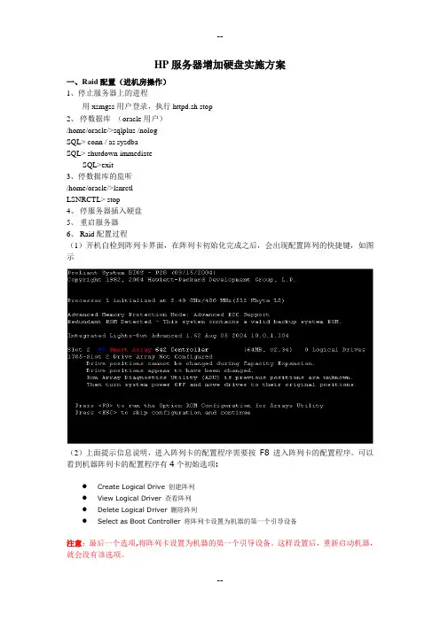
HP服务器增加硬盘实施方案一、Raid配置(进机房操作)1、停止服务器上的进程用xsmgss用户登录,执行httpd.sh stop2、停数据库(oracle用户)/home/oracle/>sqlplus /nologSQL> conn / as sysdbaSQL> shutdown immediateSQL>exit3、停数据库的监听/home/oracle/>lsnrctlLSNRCTL> stop4、停服务器插入硬盘5、重启服务器6、Raid配置过程(1)开机自检到阵列卡界面,在阵列卡初始化完成之后,会出现配置阵列的快捷键,如图示(2)上面提示信息说明,进入阵列卡的配置程序需要按F8 进入阵列卡的配置程序。
可以看到机器阵列卡的配置程序有4个初始选项:●Create Logical Drive 创建阵列●View Logical Driver 查看阵列●Delete Logical Driver 删除阵列●Select as Boot Controller 将阵列卡设置为机器的第一个引导设备注意:最后一个选项,将阵列卡设置为机器的第一个引导设备。
这样设置后,重新启动机器,就会没有该选项。
注:如果按F8键不能进入上面的阵列配置主页面而是进入此页面用键盘方向键选择“Exit”,按“Enter”进入按“Enter”后服务器检测RAID卡,这时一直按“F8”也会进入阵列配置页面如图:(3). 选择"Select as Boot Controller",出现红色的警告信息。
选择此选项,服务器的第一个引导设备是阵列卡(SmartArray 642),按"F8"进行确认。
(4).按完"F8",确认之后,提示,确认改变,必须重新引导服务器,改变才可以生效。
(5). 按"ESC"之后,返回到主界面,现在看到三个选项了。
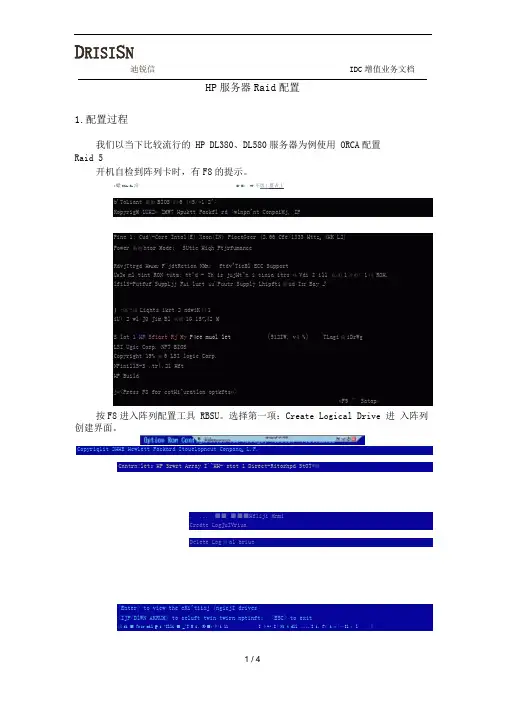
D RISI S NHP服务器Raid配置1.配置过程我们以当下比较流行的 HP DL380、DL580服务器为例使用 ORCA配置Raid 5开机自检到阵列卡时,有F8的提示。
:絵MJfc»Er洽■•■«・ WW 不恵丄监占丄按F8进入阵列配置工具 RBSU。
选择第一项:Create Logical Drive 进入阵列创建界面。
使用Space键选中、Tab键切换选项。
将三块物理硬盘都选中;选择Raid 5;由于只用了三块 sas 硬盘,故不选 spare ; Maximum Boot partition: 选择8GB maximum. 按回车创建 Raid 5 。
D RISI O N迪锐信IDC 增值业务文档0(4 Ion Kor Conf Igurdlion for firrays 曲)「・10聆7-B4 .82 BBCopyright 2BB6 Hou Lett-Pdckaj'd Development 5叩*喇.L.P-Contro l Lor i HP Srart Rrray WB8 P □ lot ] Direct fittached Storage—RHID ConT itjui at inriEi (1 RAI& S (ADG)CK3RHW 5『1RAID 1*B[1 RAW 8=^SlKrB^----- I | (J 0$ OW 建導 ^P41H&CX1 Part 2[ r R ™ 1r Bay 3»14B.8GB SAS(XI Purl 2L Bv?Bay 2* :% SfiS rxPent 211 B UM1 tB«lj 1 r 14G.OCB SflS<l!nter> to crHte 心 网ic«l driue: mb ,to vi»vig«te <UPzEKJMN RILRLKi> tu scroll ; <E5C> to returnNote : s F OT nore igurait ion opt i«ns use tte KP Arr^y Cgnf Igymt ion Ut ■ I ityi按Opt inn E SMI Conr agurai ian for Arrays , wrs inni 7.04 .02.3fi Cupijr 2BfiB Hhw Let t-Piurkdird Steve I. npnib! IB t Cunpd « L.P.Centro I Ur E HP Swri Array P4flfl . slat 1 Direct Attached Starag^haw sc lisctod d lo«jicii I dr iw uith 4 totdi I dA.tfl B 4FB O F 6? .B CB «nd RF)10 5 11 taIoramQ > PfHS's <FB> to tliH c*rnf iyurat iutt Pi-fess <£SC> lei cancel<FB> to &AW tho coitfiguaction <ESC> to canceIHole : For rwre conf igiirat ion opt ions use the HP Array COmf icfur^tian Uti lity提示设置已保存,按回车键继续。

XXXXXXX主机存储配置手册XXXXX2004年12月23日目录1 WINDOWS SERVER 2003系统配置 (3)1.1服务器分区配置 (3)1.2主机命名及IP地址配置 (4)1.3活动目录配置 (4)1.4W INDOWS SERVER 2003配置 (5)2 杀毒软件配置 (5)3 存储系统配置 (7)4 双机容错系统配置 (7)4.1D ATAWARE软件资源规划 (7)4.1.1 心跳线设置 (7)4.1.2 Ywzx-server1作为活动服务器配置 (8)4.1.3 Ywzx-server2作为活动服务器配置 (10)1Windows Server 2003系统配置1.1 服务器分区配置1.文件服务器硬盘分区在服务器上,各配有一块36G热插拔硬盘,分成两个分区,文件格式为NTFS,分区如下:●分区1(C盘):10GB,做系统盘使用;●分区2(D盘):24GB,用来安装应用程序和存储一些服务器自身数据用;D盘建立目录:D:\Program Files 用于安装应用软件;D:\backup\drivers and tools\ 用于存放服务器驱动和常用工具;D:\backup\system_bak 用于存放系统备份文件;2.病毒、网管服务器分区配置1.服务器硬盘分区在服务器上,配有一块80GB IDE硬盘,分成三个分区,文件格式为NTFS,分区如下:●分区1(C盘):10GB,做系统盘使用;●分区2(D盘):25GB,用来安装应用程序;●分区2(E盘):45GB,用来存储备份数据;2.建立目录:D:\Program Files 用于存放应用程序E:\backup\drivers and tools 用于备份各种驱动程序及常用工具E:\backup\tools\ 用于备份常用工具1.2 主机命名及IP地址配置1.3 活动目录配置基本域配置:1.4 Windows server 2003配置设置密码安全策略策略管理工具->域安全策略->安全设置->帐户策略->密码策略启用“密码必须符合复杂性要求”设置“密码最小长度值”:8位帐户密码设置将不用的帐户全部禁掉;将Win2003系统自建帐户“Administrator”设置复杂的密码,建议使用8位以上、各种字符组成的密码。
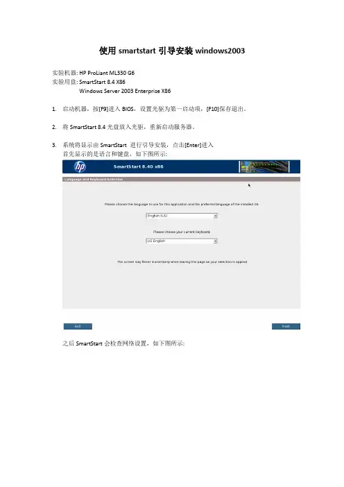
使用smartstart引导安装windows2003实验机器: HP ProLiant ML330 G6实验用盘: SmartStart 8.4 X86Windows Server 2003 Enterprise X861.启动机器,按[F9]进入BIOS,设置光驱为第一启动项,[F10]保存退出。
2.将SmartStart 8.4光盘放入光驱,重新启动服务器。
3.系统将显示由SmartStart 进行引导安装,点击[Enter]进入首先显示的是语言和键盘,如下图所示:之后SmartStart会检查网络设置,如下图所示:接下来是最终用户许可说明,如下图所示:进入到SmartStart的配置首界面:首先在上方的区域,会看到服务器的信息,如:服务器型号为:ProLiant ML330 G6,ROM的版本号为:W07 03/30/2010,物理内存大小为4G在操作选择区有五个选项,分别是:(1)Install(安装新的操作系统)(2)Run Saved Installation(运行已保存的操作系统)(3)Maintenance(维护)(4)System Erase(低格系统)(5)Reboot(重启服务器)4.配置阵列(1)在HOME主页面下选择Maintenance,进入维护界面,如下图所示:可以看到里面有五个选项:HP Light-Out Configuration (配置Light-Out)HP Array Configuration and Diagnostics(配置及检测阵列)HP Insight Diagnostics(内部诊断)Create a bootable USB Key(制作可引导的USB Key)USB Punchout Creation Utility()(2)点击HP Array Configuration and Diagnostics进入阵列配置界面,如下图所示:首先可以看到三个标签Configuration (配置阵列)Diagnostics(检测阵列)Wizards(向导)点击Configuration,下方会有一个选择阵列卡的下拉菜单,选择服务器上的阵列卡SmartArray B110i SATA RAID后会显示出此阵列卡的当前配置情况,如下图所示:可以看到当前阵列卡已配置好一个阵列,但还有一块硬盘未作配置,选择右边的Clear Configuration将当前阵列配置清除,清除后可以看到当前服务器上有两块SATA硬盘,容量分别为500G和250G,如下图所示:在右边的选项中选择Create Array,创建阵列,如下图所示:创建好后可以看到左边显示区中已经有一个已建好的阵列,可使用的大小是465.7GB5.配置logical driver在左边的显示区中选择创建好的阵列后,点击右边界面中的Create Logical Drive创建逻辑磁盘,如下图所示:创建好的逻辑磁盘如下图所示:可以看到,一块100G的磁盘作了RAID0,另一块400G的磁盘作了RAID16.安装操作系统重新返回SmartStart引导的首界面,如下图所示:点击Install,进行操作系统的安装,首先需要选择安装操作系统的逻辑磁盘,如下图所示:选择作RAID0的Disk1安装操作系统,点击Next选择好要安装的操作系统版本,点击Next选择安装操作系统的源类型,如下图所示:选择文件类型及引导分区的大小,如下图所示:在选择引导分区大小的时候,默认为最大,也就是把安装操作系统的逻辑分区全部用来安装操作系统,当然也可以根据实际需要自定义引导分区。
【最新整理,下载后即可编辑】
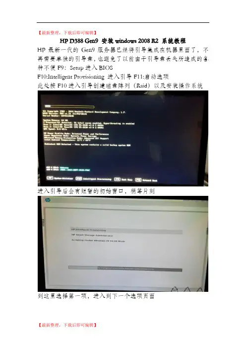
HP D388 Gen9 安装windows 2008 R2 系统教程
HP最新一代的Gen9服务器已经将引导集成在机器里面了,不再需要单独的引导盘,也避免了以前由于引导盘丢失所造成的各种不便 F9:Setup 进入BIOS
F10:Intelligent Provisioning 进入引导 F11:启动选项
此处按F10进入引导创建磁盘阵列(Raid)以及安装操作系统进入引导后会有短暂的初始窗口,稍等片刻
到这里选择第一项,进入到下一个选项页面
到这里选择第二个,进入维护模式
在这里选择SSA,进入后,可以看到阵列卡信息P440ar
创建阵列
将硬盘全选
选择创建Raid1
确认信息,创建成功
返回配置和安装,安装操作系统
进入安装系统步骤
第二步,这里选用的是用优盘安装,光盘安装选择Disc即可
选择镜像
进行系统配置选择
确认信息,进入安装
等待进度条走完
系统重启,进入系统安装界面
系统自动安装
提醒:注意细节选项,根据自己的需求进行选择更改【最新整理,下载后即可编辑】。
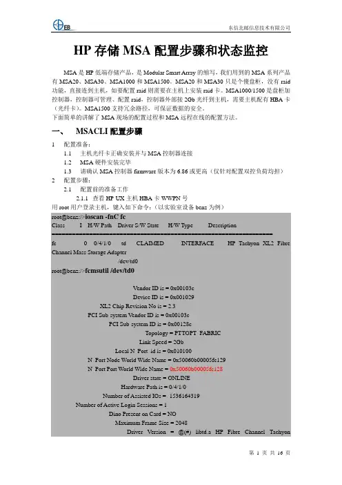
HP存储MSA配置步骤和状态监控MSA是HP低端存储产品,是Modular Smart Array的缩写,我们用到的MSA系列产品有MSA20、MSA30、MSA1000和MSA1500。
MSA20和MSA30只是个傻盘柜,没有raid 功能,直接连到主机,如要配置raid则需要在主机上安装raid卡。
MSA1000/1500是盘柜加控制器,控制器可管理、配置raid,控制器外部接2Gb光纤到主机,需要主机配有HBA卡(光纤卡)。
MSA1500支持冗余路径,可保证数据的安全。
下面简单的讲解了MSA现场的配置过程和MSA远程在线的配置方法。
一、MSACLI配置步骤1配置准备:1.1主机光纤卡正确安装并与MSA控制器连接1.2MSA硬件安装完毕1.3请确认MSA控制器firmware版本为6.86或更高(仅针对配置双控负荷均担)2配置步骤:2.1配置前的准备工作2.1.1查看HP-UX主机HBA卡WWPN号用root用户登录主机,键入如下命令:(以实验室设备benz为例)root@benz:/>ioscan -fnC fcClass I H/W Path Driver S/W State H/W Type Description=================================================================fc 0 0/4/1/0 td CLAIMED INTERFACE HP Tachyon XL2 Fibre Channel Mass Storage Adapter/dev/td0root@benz:/>fcmsutil /dev/td0V endor ID is = 0x00103cDevice ID is = 0x001029XL2 Chip Revision No is = 2.3PCI Sub-system Vendor ID is = 0x00103cPCI Sub-system ID is = 0x00128cTopology = PTTOPT_FABRICLink Speed = 2GbLocal N_Port_id is = 0x010100N_Port Node World Wide Name = 0x50060b00005fc129N_Port Port World Wide Name = 0x50060b00005fc128Driver state = ONLINEHardware Path is = 0/4/1/0Number of Assisted IOs = -1536164319Number of Active Login Sessions = 1Dino Present on Card = NOMaximum Frame Size = 2048Driver Version = @(#) libtd.a HP Fibre Channel TachyonTL/TS/XL2 Driver B.11.11.12 PATCH_11.11 (PHSS_31326) /ux/kern/kisu/TL/src/common/wsio/td_glue.c: Sep 5 2005, 10:14:40注意上面红色的号码,在MSA配置中的格式为:50060b00-005fc1282.1.2查看Linux主机HBA卡WWPN号用root用户登录主机,键入如下命令:(以实验室设备jetta为例)[root@jetta ~]# cat /proc/scsi/qla2xxx/0QLogic PCI to Fibre Channel Host Adapter for QLA2340:Firmware version 3.03.18 IPX, Driver version 8.01.02-d4ISP: ISP2312, Serial# D08964Request Queue = 0x37640000, Response Queue = 0x37630000Request Queue count = 2048, Response Queue count = 512Total number of active commands = 0Total number of interrupts = 160Device queue depth = 0x10Number of free request entries = 2047Number of mailbox timeouts = 0Number of ISP aborts = 0Number of loop resyncs = 0Number of retries for empty slots = 0Number of reqs in pending_q= 0, retry_q= 0, done_q= 0, scsi_retry_q= 0Host adapter:loop state = <DEAD>, flags = 0x1a03Dpc flags = 0x4000000MBX flags = 0x0Link down Timeout = 008Port down retry = 016Login retry count = 016Commands retried with dropped frame(s) = 0Product ID = 4953 5020 2020 0002SCSI Device Information:scsi-qla0-adapter-node=200000e08b84e4b6;scsi-qla0-adapter-port=210000e08b84e4b6;FC Port Information:SCSI LUN Information:(Id:Lun) * - indicates lun is not registered with the OS.若要查看主机上的第二快HBA卡,命令为cat /proc/scsi/qla2xxx/12.1.3查看AIX主机HBA卡WWPN号用root用户登录主机,键入如下命令:(以湖南SCP11A为例)root@SCP11A>lsattr -El dac0GLM_type low GLM type Falsealt_held_reset no Alternate held in reset Falsecache_size 128 Cache Size in MBytes Falsecontroller_SN 1T54396785 Controller serial number Falsectrl_type 1722-600 Controller Type Falselocation Location Label Truelun_id 0x0 Logical Unit Number Falsenode_name 0x200800a0b81f56e8 FC Node Name Falsepassive_control no Passive controller Falsescsi_id 0x10000 SCSI ID Falseutm_lun_id 0x001f000000000000 Logical Unit Number Falseww_name 0x200900a0b81f56e9World Wide Name False注意上面红色的号码,在MSA配置中的格式为:200900a0-0b81f56e92.1.4连接MSA控制器方法:找一台PC机,通过阵列随机带的黑色串口线(维护线,一端串口,一端RJ45口),将PC机和阵列的控制器连接起来。

磁盘阵列柜配置手册磁盘阵列柜配置1.物理连接(1)按图1-1所示,将磁盘阵列柜上的1、2号HBA卡控制器分别与主、从数据库服务器的HBA卡连接。
a)按图1-1所示,将主、从数据库服务器的串口端口连接。
图1-1注:具体实物如下所示:磁盘阵列柜服务器2.操作终端设置(1)使用网线将笔记本电脑与正在使用的HBA卡控制器连接(插入的控制器为正在使用)。
(2)配置笔记本电脑IP地址为10.0.0.200做为MSA 2000的控制机器。
如图1-2所示:(3)打开控制机器的IE 浏览器,地址栏输入:http://10.0.0.2/3(10.0.0.2为1号控制器的IP ,10.0.0.3为2号控制器的IP)回车,进入MSA 2000的管理配置界面,并输入用户名:manage;密码:!manage 如图1-3所示:3.磁盘阵列柜配置 3.1创建阵列图1-2图1-3(1)进入配置界面后,在左边选择”manage ”菜单,选择”creat a vdisk ”,在左边选择手动创建”manual virtual disk created ”,如图1-4所示:(2)输入创建的阵列的名称,如”msa20”选择需要创建的阵列的类型,RAID5 如图1-5所示:(3)勾选需要做阵列的硬盘,假如需要使用一个硬盘做在线的备用盘,需要在“would you like to dedicated spare drives for this virtual disk ”选图1-4图1-5择”yes ”,点击”continue ”,如图1-6所示:(4)勾选需要做” spare disk ”在线备用的硬盘,点击”continue ”,如图1-7所示:3.2创建卷(Volum )(1)选择硬盘创建中,选择创建2个卷,点击 “creat virtual disk ”如图图1-6图1-71-8所示:(2)输入两个卷的容量,点击”add volumes ”,注意,卷的容量必须为整数,若输入的容量为小数,则卷的创建失败。
HP服务器上安装和管理HP 磁盘柜MSA500G23937207649(Redhat Linux AS3.0字符环境)名目:一、磁盘柜硬件安装;二、驱动和工具软件安装;三、阵列配置;四、系统监控先给服务器安装操作系统Redhat Linux AS3.0。
磁盘柜硬件安装默认的SCSI口认不到MSA500G2操纵器,因此服务器必须插一块Smart Array642卡(每台MSA500G2都带2块Smart Array642卡),由于SA642是全长的PCI-X卡,因此服务器必须能提供全长的PCI-X插槽。
连接线缆,先开磁盘柜,等2分钟后再开服务器。
驱动和工具软件安装1、以超级用户root登录Linux系统,将随盘柜或自己下载的HP SmartSt art光盘放入服务器光驱中。
)#mount –t iso9660 /dev/cdrom /mnt#cd /mnt/compaq/csp/linux#ls *.sh –l2、执行看到的.sh文件,例如#./install760.sh在那个过程中会回答一些系统治理咨询题,一部份是有关SNMP有关的,一部份是与治理帐号和安全的,能够过后再配(本文第四节),能够使用默认设置,必须输入的先随便输入。
那个过程会安装HP驱动(包括网卡驱动)、治理和配置软件。
3、检查安装成效#lsmod |grep cciss应该显示 ciss 。
如没有:#insmod cciss用vi编辑 /etc/rc.local,加入:insmod ccisscpqacuxe –R重启服务器#cd /#umount /mnt#reboot阵列配置有三种方式配置阵列:方法1:用HP SmartStart CD启动服务器,启用ACU(Array Configurati on Utility)配置阵列;(图形界面,最方便使用);方法2:用Linux下命令行配置(能够做ACU所有工作,又增加改MSA 500G2名称等功能);方法3:在网络环境下,在一台PC上用扫瞄器登录服务器治理界面(Sy stem Management Homepage),在里面启用ACU-XE,界面和方法1一样。
HP双服务器+HP MSA2000磁盘阵列柜的双机热备方案简述一、双机热备简述:由两台服务器+磁盘阵列柜构成双机热备系统,在两台服务器中安装所有的服务模块。
由两台服务器+共享磁盘阵列柜构成高可用系统。
通过系统的服务监测模块来互相监测对方的心跳及服务,服务监测模块通过网络和串口来定时监测对方心跳,该系统具有三种运行状态:1.服务器A运行服务1,且在工作时使用磁盘阵列,服务器B运行服务2。
2. Fail Over。
a)当服务器A出现故障时:服务器B监测到服务器A出现故障,接管服务器A的IP地址,然后再mount上磁盘阵列,最后启动服务1。
b)当服务器B出现故障时:服务器A监测到服务器B出现故障,监管服务器B的IP地址,然后启动服务2。
3. Take Over。
故障服务器恢复后,两台服务器又开始工作,回到状态1。
快客电邮系统包括了服务监测模块,所以不必要额外采购第三方的HA软件。
该方案的特点是:故障切换时间短(小于2分钟),在故障切换过程中数据的完整性较好,但是需要在硬件投入上增加更多的成本(磁盘阵列柜)。
二、方案介绍本方案中采用的是基于微软的MSCS双机热备来防范服务器单点故障,所以采用MicrosoftWindows Server 2003 Enterprise Edition中自带MSCS(Microsoft Cluster Service)的服务或双机软件来实现双机热备。
该方案是由两台HP Proliant ML570服务器和一个HP MSA2000 SAS共享磁盘阵列柜组成,系统拓扑如图所示:在这个容错方案中,Windows2003 Enterprise Server操作系统和应用程序安装在两台服务器的本地系统盘上,应用系统的数据是通过磁盘阵列集中管理和数据备份的,极大地保护了数据的安全性和保密性。
因为用户的数据存放在外部HP MSA2000SAS共享磁盘阵列中,在一台服务器出现故障时,备机主动替代主机工作,保证服务不间断。
HP服务器上安装和管理HP磁盘柜MSA500G2(Redhat Linux AS3.0字符环境)目录:●一、磁盘柜硬件安装;page 1●二、驱动与工具软件安装;page 1●三、阵列配置;page 2●四、系统监控 page12先给服务器安装操作系统Redhat Linux AS3.0。
一、磁盘柜硬件安装默认的SCSI口认不到MSA500G2操纵器,因此服务器务必插一块SmartArray642卡(每台MSA500G2都带2块Smart Array642卡),由于SA642是全长的PCI-X卡,因此服务器务必能提供全长的PCI-X插槽。
连接线缆,先开磁盘柜,等2分钟后再开服务器。
二、驱动与工具软件安装1、以超级用户root登录Linux系统,将随盘柜或者自己下载的HP SmartStart光盘放入服务器光驱中。
)#mount –t iso9660 /dev/cdrom /mnt#cd /mnt/compaq/csp/linux#ls *.sh –l2、执行看到的.sh文件,比如#./install760.sh在这个过程中会回答一些系统管理问题,一部份是有关SNMP有关的,一部份是与管理帐号与安全的,能够过后再配(本文第四节),能够使用默认设置,务必输入的先随便输入。
这个过程会安装HP驱动(包含网卡驱动)、管理与配置软件。
3、检查安装效果#lsmod |grep cciss应该显示 ciss 。
如没有:#insmod cciss用vi编辑 /etc/rc.local,加入:insmod ccisscpqacuxe –R4、重启服务器#cd /#umount /mnt#reboot三、阵列配置有三种方式配置阵列:●方法1:用HP SmartStart CD启动服务器,启用ACU(Array ConfigurationUtility)配置阵列;(图形界面,最方便使用);●方法2:用Linux下命令行配置(能够做ACU所有工作,又增加改MSA500G2名称等功能);●方法3:在网络环境下,在一台PC上用浏览器登录服务器管理界面(System Management Homepage),在里面启用ACU-XE,界面与方法1一样。
HP服务器的安装上架2013年06月目录1接收CSAE单安装前以下问题进行确认 (2)1.1:咨询销售及负责人提供相关服务信息: (2)1.2:安装地点及环境条件: (2)1.3:确认实施时间 (2)1.4:送货前设备硬件检测 (2)1.5:技术配置要求以及相关文档 (2)2客户现场 (2)2.2:开箱检验 (3)2.3:机房确认机柜组成,机柜摆放及设备安装位置 (3)2.4:服务器上架及原则: (3)2.5:理线要求以及相关工具 (4)2.6:标签规格及作用: (5)2.7:上电,现场硬件检测(HP工具)有流程: (5)2.8:根据客户要求安装及配置 (5)2.9:清场验收。
(6)3.0:客户确认通知销售结单离开 (6)1接收CSAE单安装前以下问题进行确认1.1:咨询销售及负责人提供相关服务信息:1.1.1服务器的数量、型号以及选件(如:硬盘的大小和数量),服务器详细单。
1.1.2操作系统确认:安装配置要求。
1.2:安装地点及环境条件:1.2.1 机柜电流,温度、湿度及UPS品牌和供电电流。
1.2.2机柜所在机房确切位置,设备安装所在机柜位置。
1.3:确认实施时间1.4:送货前设备硬件检测1.5:技术配置要求以及相关文档2客户现场2.1:工作流程图2.2:开箱检验2.2.1:根据公司送货设备清单和邮件附注设备清单核对,一一点清验货注意相关配件。
2.3:机房确认机柜组成,机柜摆放及设备安装位置2.3.1:机柜组成(19英寸标准机柜有24U,42U等类型)2.3.2:机柜准备2.3.2.1:调平机柜:机柜必须安放在一个稳固的地方,调节机柜底部的四个调节支脚,使机柜平稳的安放于地面。
同时拆下机柜门以方便导轨安装2.3.2.2:机柜接地:为了避免电击危险,必须在机柜内安装一个接地装置。
2.3.2.3: 温度:如果服务器安装在机柜内,服务器的操作、工作温度,不能低于5℃,不能高于25℃。
2.3.2.4:通风:服务器集群用的机柜必须为服务器的前部提供足够的风流来散热,并且必须保证能够每小时排放4100Btu的热量。
HP服务器上安装和管理HP 磁盘柜MSA500G2(Redhat Linux AS3.0字符环境)目录:●一、磁盘柜硬件安装;page 1●二、驱动和工具软件安装;page 1●三、阵列配置;page 2●四、系统监控 page12先给服务器安装操作系统Redhat Linux AS3.0。
一、磁盘柜硬件安装默认的SCSI口认不到MSA500G2控制器,因此服务器必须插一块Smart Array642卡(每台MSA500G2都带2块Smart Array642卡),由于SA642是全长的PCI-X卡,因此服务器必须能提供全长的PCI-X插槽。
连接线缆,先开磁盘柜,等2分钟后再开服务器。
二、驱动和工具软件安装1、以超级用户root登录Linux系统,将随盘柜或自己下载的HP SmartStart光盘放入服务器光驱中。
(最新SmartStart下载地址:/support/files/server/us/subscription/PSM_subscriptio n.html)#mount –t iso9660 /dev/cdrom /mnt#cd /mnt/compaq/csp/linux#ls *.sh –l2、执行看到的.sh文件,例如#./install760.sh在这个过程中会回答一些系统管理问题,一部份是有关SNMP有关的,一部份是与管理帐号和安全的,可以过后再配(本文第四节),可以使用默认设置,必须输入的先随便输入。
这个过程会安装HP驱动(包括网卡驱动)、管理和配置软件。
3、检查安装效果#lsmod |grep cciss应该显示 ciss 。
如没有:#insmod cciss用vi编辑 /etc/rc.local,加入:insmod ccisscpqacuxe –R4、重启服务器#cd /#umount /mnt#reboot三、阵列配置有三种方式配置阵列:●方法1:用HP SmartStart CD启动服务器,启用ACU(Array ConfigurationUtility)配置阵列;(图形界面,最方便使用);●方法2:用Linux下命令行配置(可以做ACU所有工作,又增加改MSA500G2名称等功能);●方法3:在网络环境下,在一台PC上用浏览器登录服务器管理界面(SystemManagement Homepage),在里面启用ACU-XE,界面和方法1一样。
MSA500G2共有14颗146GB磁盘,建议仅定义一个磁盘组(Array),包含13颗磁盘,此磁盘组划分成4个逻辑盘,分别标记为logical disk1-4,下图,每个逻辑盘都用到13个硬盘的一部分(在操作系统看来是4个物理盘)每个逻辑盘采用RAID5模式,第14颗硬盘作为热备援盘。
当阵列中某个物理磁盘损坏时,自动加入到阵列中,参与阵列,此时系统从其它磁盘读数据,运算后写入此磁盘,此过程称为重构(rebuild)。
从以下(一)、(二)、(三)中挑一个方法来配置成上述效果。
(一)方法11、用HP SmartStart CD启动服务器;启用ACU(Array ConfigurationUtility)工具(要用到鼠标):2、ACU会自动扫描所有的阵列卡(机器内部集成的,Smart Array 642)和MSA500G2;点中MSA500G2;3、观察检测到的硬盘,看有没有事先的设置,如果有且数据不用,删除掉。
4、先创建磁盘组(Create Array):5、再分别创建4个逻辑盘(Create Logical Drive):根据需要配置每个逻辑盘的参数:RAID级别,条带大小(stripe size),逻辑盘大小(Logical Drive Size,最后一个用默认)。
ss 是条带大小(stripe size),单位是KB;(性能调优:a.混合读写:使用默认;b.主要连续读,例如语音和视频应用:stripe size调大;c.主要是写:例如图象处理:RAID5或6用小的stripe size,RAID0和1+0用大的stripe size);. raid 级别必须是本控制器能支持的,缺省是RAID6(ADG,可损坏任意两颗硬盘,但性能比RAID5略低8%~15%)5、设置备援盘注:以上配置(RAID5+热备援)与选择14颗硬盘做RAID6(ADG)相比,磁盘利用率都是(14-2)/14; RAID6可靠性更高,但是性能比RAID5低10%左右。
保存,退出ACU。
(二)方法2:用命令行的阵列配置1、以超级用户root登录Linux系统,输入阵列配置命令行#cpqacuxe -stop#hpacucli进入阵列配置命令行模式,标记是“=>”;可以敲help 进行帮助,常见有关术语见下全称缩写解释全称缩写解释adapterid ai 适配器ID号serialnumber sn 控制器序列号arrayaccelerator aa 缓存cacheratio cr 读写缓存比率logicaldrive ld 逻辑盘,即能被操作系统看见的卷physicaldrive pd 真实的物理硬盘,操作系统不可见chassisname ch 盘柜名字,可自己修改controller ctrl 控制器2、扫描和察看阵列卡=> rescan=> ctrl all show此时应该可以看到SA642和MSA500G2两个控制器,可能是这样显示:MSA500G2 in 22K9LYPN44 (sn=xxxxxxxxxxxxxxxxxx xxxxxxxxxxxxx)Smart Array642 in slot 0 (sn=xxxxxxxxxxxxxxxx )3、将冗长的盘柜名字从22K9LYPN44改成好用好记的=> ctrl ch=22K9LYPN44 modify ch=21cn4、设置目标控制器,这样后面命令都是指针对它,可以减少命令行长度=>set target ctrl ch=21cn5、查看控制器和其所有物理磁盘和逻辑盘=>show=>pd all show=>ld all show6、选择物理盘,组成磁盘组(Array),创建逻辑盘(卷);一个磁盘组可以划成多个逻辑盘,RAID级别是在逻辑盘指定的,即允许同一磁盘组的不同逻辑盘各采用不同RAID级别。
例如本测试里将14颗磁盘做进一个磁盘组,再将它划成5个大小接近的逻辑盘:=>create type=ld drives=1:1-1:13 size=420000 ss=32 raid=5=>create type=ld drives=1:1-1:13 size=420000 ss=32 raid=5=>create type=ld drives=1:1-1:13 size=420000 ss=32 raid=5=>create type=ld drives=1:1-1:13 ss=32 raid=5以上命令行中:. drives也可以随意选择非连续盘,用逗号(,)分开;. size 后数字的单位是MB;省略的话是采用所有可用空间做逻辑盘(见以上第4行);ss 是条带大小(stripe size),单位是KB;(性能调优:a.混合读写:使用默认;b.主要连续读,例如语音和视频应用:stripe size调大;c.主要是写:例如图象处理:RAID5或6用小的stripe size,RAID0和1+0用大的stripe size);. raid 级别必须是本控制器能支持的,缺省是RAID6(ADG,可损坏任意两颗硬盘,但性能比RAID5略低8%~15%)7、配置备援盘=>add spares=1:148、查看效果=>ld all show=>ld 1 show=>ld 2 show=>ld 3 show=>ld 4 show9、为逻辑盘启用阵列控制器缓存(如果新控制器或新缓存在,加电后,电池充电期间,缓存会被控制器禁用,一段时间后缓存才可用)=> ld all modify aa=enable10、修改阵列控制器缓存的读写比率,默认设为50% 比50%,可以根据应用环境自行调整。
=> modify cr=50/50*11、为物理盘启用缓存(MSA500G2不支持)=> modify dwc=enable其它设置和命令参阅文档《HP Array Configuration Utility User Guide》的“Using the Command Line Interface”一节。
12、退出=>quit#cpqacuxe –R(三)方法3第四章第(二)节配好后,从网上其它计算机访问本服务器的管理网页,:http://机器名或IP:2301或http s://机器名或IP:2381选择HP Array Configuration Utility;具体配置方法同第(一)节。
(四)验证设备名#fdisk /dev/cciss/c0d0[root@localhost init.d]# fdisk /dev/cciss/c0d0The number of cylinders for this disk is set to 105412.There is nothing wrong with that, but this is larger than 1024,and could in certain setups cause problems with:1) software that runs at boot time (e.g., old versions of LILO)2) booting and partitioning software from other OSs(e.g., DOS FDISK, OS/2 FDISK)Command (m for help): pDisk /dev/cciss/c0d0: 440.4 GB, 440402968064 bytes255 heads, 32 sectors/track, 105412 cylindersUnits = cylinders of 8160 * 512 = 4177920 bytesDevice Boot Start End Blocks Id System Command (m for help): q#fdisk /dev/cciss/c0d1#fdisk /dev/cciss/c0d2#fdisk /dev/cciss/c0d3如果有2个msa500G2,另外的设备名就是/dev/cciss/c1d0/dev/cciss/c1d1/dev/cciss/c1d2/dev/cciss/c1d3HP DL380G5 内置E200阵列卡配的内置硬盘的设备名是:/dev/cciss/c2d0(如果分了多个逻辑盘就依次增加)/dev/cciss/c2d1....设备根据具体应用要求使用;一般先建分区(fdisk里用n);然后再直接使用裸设备(例如 /dev/cciss/c0d0p0);也可做成文件系统(#mkfs 设备名)四、系统监控(一)Linux下基于命令行的察看#cpqacuxe -stop#hpacucli=> ctrl ch=21cn show=> ctrl ch=21cn ld all show=> ctrl ch=21cn ld 1 show=> ctrl ch=21cn pd all show=> ctrl ch=21cn pd 1 show如果一颗硬盘坏,上述含pd命令可看到。