史赛克动力系统彩页-180918
- 格式:pdf
- 大小:1.62 MB
- 文档页数:6

瑞典SEP B-13混合动力装甲车辆战术系统瑞典虽然是永久中立国,不参加任何军事集团,但军工技术却令人瞩目,而且所有军种的主要武器装备,都是自行生产的。
瑞典在装甲车辆方面的成就是公认的,技术方面在全世界居领先地位,包括美国陆军新型“斯特赖克”装甲车都引进了瑞典的技术。
瑞典已经成功的研制出世界上第一种全电动模块装甲战术系统,包括轮式和履带式两种规格,将军用装甲车辆的开发,引入一个全新阶段。
瑞典SEP B-13模块装甲战术系统瑞典阿尔维斯·赫格隆公司正在发展一种先进的“多用途装甲平台”(SEP)B-13模块装甲战术系统,综合一套全电传动系统和可折卸、可互换任务模块系列组件。
主要特点是:全电传动系统真正将发动机和驱动系统分开,发动机带动发电机产生电力并同时向蓄电系统储存,通过电缆将动力传输到电动机来驱动;模块化装甲战术系统、车辆的履带式或轮式平台和乘员模块之间是独立的,可快速拆卸、可互换和可单独运输。
只要根据需要换装不同的任务模块,就能组合出不同用途装甲车辆,多达24种类型。
一、瑞典SEP发展计划瑞典SEP发展工作从1996年开始,分履带式系统和轮式系统两大类型,主要由瑞典阿尔维斯·赫格隆公司负责开发。
瑞典的全电动模块装甲车辆计划一经推出就受众多国家青睐,共同参加研制,主要有芬兰、荷兰、意大利、希腊、瑞典和土耳其等六个国家。
2000年11月,第一辆SEP-履带式示范车辆交付给瑞典国防装备局(FMV)用于评估。
到2003年,车辆已经进行各种不同的试验行程达2,000 公里。
瑞典国防装备局在2001年11月,授予阿尔维斯·赫格隆公司开发SEP-轮式型号合同。
第一辆在履带式系统基础上开发的SEP-轮式原型示范车辆。
在2003年瑞典国防装备局授予一份风险减少合同给阿尔维斯·赫格隆公司,制造第二辆SEP-履带式测试平台车辆。
2004年4月22日,瑞典阿尔维斯·郝格隆茨公司向瑞典国防装备局交付了第一辆SEP-轮式原型示范车辆。


SECHRIST INDUSTRIES, INC.Service Manual Hydraulic and Standard StretchersHydraulic Models:P/N 21465Preventative Maintenance Checklist3. . . . . . . . . . . . . . . . . . . . . . . . . . . . . . . . . . . . . . . . . . . . . . . . . . . . . . . . . .. . . . . . . . . . . . . . . . . . . . . . . . . . . . . . . . . . . . . . . . . . . . . . . . . . . . . . . . . . . . . . . . . . . . . . . . . . . . . . . . . . Cleaning4 Service Information. . . . . . . . . . . . . . . . . . . . . . . . . . . . . . . . . . . . . . . . . . . . . . . . . . . . . .Caster Cover Installation and Removal5. . . . . . . . . . . . . . . . . . . . . . . . . . . . . . . . . . . . . . . . . . . . . . . . . . . . . . . . . . . . .Caster Assembly Replacement5 . . . . . . . . . . . . . . . . . . . . . . . . . . . . . . . . . . . . . . . . . . . . . . . . . . . . . . . . . . . . . . . . . . . . . .Brake Rod Removal6 Brake Ring Removal7 . . . . . . . . . . . . . . . . . . . . . . . . . . . . . . . . . . . . . . . . . . . . . . . . . . . . . . . . . . . . . . . . . . . . . .. . . . . . . . . . . . . . . . . . . . . . . . . . . . . . . . . . . . . . . . . . . . . . . . . . . . . . . . . . . . . . . . . . . . .Fifth Wheel Removal7. . . . . . . . . . . . . . . . . . . . . . . . . . . . . . . . . . . . . . . . . . . . . . . . . . . . . . . . . . . . . . . . .Siderail Latch Adjustment8 Assembly Drawings and Parts Lists. . . . . . . . . . . . . . . . . . . . . . . . . . . . . . . . . . . . . . . . . . . . . . . . . . . . . . . . . . . . . .Fixed Height Base Assembly9. . . . . . . . . . . . . . . . . . . . . . . . . . . . . . . . . . . . . . . . . . . . . . . . . . .Base Assembly with Standard Brakes10, 11 . . . . . . . . . . . . . . . . . . . . . . . . . . . . . . . . . . . . . . . . . . . . . . . . . . . . . . . . . . . . . . . . . . . .Brake Rod Assembly12 . . . . . . . . . . . . . . . . . . . . . . . . . . . . . . . . . . . . . . . . . . . . . . . . . . . . . . . . . . . . . . . . . . . . .Drive Link Assembly13 . . . . . . . . . . . . . . . . . . . . . . . . . . . . . . . . . . . . . . . . . . . . . . . . . . . . . . . . . . . . . . . . .Fifth Wheel Assembly14, 15 . . . . . . . . . . . . . . . . . . . . . . . . . . . . . . . . . . . . . . . . . . . . . . . . . . . . . . . . . . . . . . . . . . . . . . . .Caster Assembly16. . . . . . . . . . . . . . . . . . . . . . . . . . . . . . . . . . . . . . . . . . . . . . . . . . . . . . . . . . . . . .Push Bar Gurney Assembly17. . . . . . . . . . . . . . . . . . . . . . . . . . . . . . . . . . . . . . . . . . . . . . . . . . . . .Fixed Height Base Labeling Assembly18 Fixed Height Base Labeling Assembly − Pushbar Gurney19. . . . . . . . . . . . . . . . . . . . . . . . . . . . . . . . . . . . .. . . . . . . . . . . . . . . . . . . . . . . . . . . . . . . . . . . . . . . . . . . . . . . . . . . . . . . . . . . . .Hydraulic Base Assembly20−24. . . . . . . . . . . . . . . . . . . . . . . . . . . . . . . . . . . . . . . . . . . . . . . . . . . . . . . . . . . . . .Release Pedal Assembly25, 26 . . . . . . . . . . . . . . . . . . . . . . . . . . . . . . . . . . . . . . . . . . . . . . . . . . . . . . . . . . . . . . . . . . .Pump Pedal Assembly27. . . . . . . . . . . . . . . . . . . . . . . . . . . . . . . . . . . . . . . . . . . . . . . . . . . . . .End Control Base Labeling Assembly28. . . . . . . . . . . . . . . . . . . . . . . . . . . . . . . . . . . . . . . . . . . . . . . . . . . .Litter Assembly − Fixed Height Base29−31. . . . . . . . . . . . . . . . . . . . . . . . . . . . . . . . . . . . . . . . . . . . . . . . . . . . . . .Litter Assembly − Hydraulic Base32−35. . . . . . . . . . . . . . . . . . . . . . . . . . . . . . . . . . . . . . . . . . . . . . . . . . . . . . . . . . . . . .Folddown Siderail Assembly36. . . . . . . . . . . . . . . . . . . . . . . . . . . . . . . . . . . . . . . . . . . . . . . . . . . . . . . . . . . . .Litter Release Rod Assembly37. . . . . . . . . . . . . . . . . . . . . . . . . . . . . . . . . . . . . . . . . . . . . . . . . . . . . . . . . . . . . . . . . .Push Handle Assembly38 Transfer Dolly Assembly39. . . . . . . . . . . . . . . . . . . . . . . . . . . . . . . . . . . . . . . . . . . . . . . . . . . . . . . . . . . . . . . . .. . . . . . . . . . . . . . . . . . . . . . . . . . . . . . . . . . . . . . . . . . . . . . . . . . . . . . . . . . . . . . . . . . . . . .I.V. Pole Assembly40. . . . . . . . . . . . . . . . . . . . . . . . . . . . . . . . . . . . . . . . . . . . . . . . . . . . . . . . . . . . . . . . . . . . . . . . . . . . . . . . . Warranty41Sechrist IndustriesDeclares that the medical devices described hereafter:Gurney System for the following models:2146521266215022146421487are in conformity with the essential requirements and provisions of Council Directive 93/42/EEC. Conformity has been achieved under Annex VII.Preventative MaintenanceCHECKLISTALL STRETCHERS:All fasteners secure (reference assembly prints)Siderails move and latch properly (Stretchers 21502, 21464, 21465, 21266)All casters lock with brake pedal engagedSteer function working properlyAll casters secure and swiveling properlyGround chain intactI.V. pole intact and operating properlyOxygen bottle holder intact and operating properlyHead rest operates and latches properly (on Stretcher P/N’s 21464, 21465)No rips or cracks in mattress coverLubricate where requiredAccessories and mounting hardware in good condition and working properlyHYDRAULIC STRETCHERS (P/N’S 21465, 21266):No leaks at hydraulic connectionsHydraulic jacks holding properlyHydraulic drop rate set properlyHydraulic oil level sufficientSerial No. ______________ __________________________________________ __________________________________________ ____________________________ Completed By: _________________________________ Date: _____________NOTEReferences to the right or left side of the stretcher refer to the right and left sides of a patient lying face up on the stretcher.CleaningHand wash all surfaces of the stretcher with warm water and mild detergent. Dry thoroughly. DO NOT STEAM CLEAN, PRESSURE WASH, HOSE OFF OR ULTRASONICALLY CLEAN. Using these methods of cleaning is not recommended and may void this product’s warranty.In general, when used in those concentrations recommended by the manufacturer, either phenolic type or quaternary type disinfectants can be used. Iodophor type disinfectants are not recommended for use be-cause staining may result. The following products have been tested by the Herculite Laboratory and have been found not to have a harmful effect WHEN USED IN ACCORDANCE WITH MANUFACTURERS REC-OMMENDED DILUTION.*Quaternary Germicidal Disinfectants, used as directed, and/or Chlorine Bleach products, typically 5.25% So-dium Hypochlorite in dilutions ranging between 1 part bleach to 100 parts water, and 2 parts bleach to 100 parts water are not considered mild detergents. These products are corrosive in nature and may cause dam-age to your stretcher if used improperly. If these types of products are used to clean patient handling equip-ment, measures must be taken to insure the stretchers are rinsed with clean water and thoroughly dried fol-lowing cleaning. Failure to properly rinse and dry the stretchers will leave a corrosive residue on the surface of the stretcher, possibly causing premature corrosion of critical components. Failure to follow the above directions when using these types of cleaners may void this product’s warranty.REMOVAL OF IODINE COMPOUNDSThis solution may be used to remove iodine stains from mattress cover surfaces.1. Use a solution of 1−2 tablespoons Sodium Thiosulfate in a pint of warm water to clean the stained area.Clean as soon as possible after staining occurs. If stains are not immediately removed, allow solution to soak or stand on the surface.2. Rinse surfaces which have been exposed to the solution in clear water before returning bed to service.CASTER COVER INSTALLATION AND REMOVALDouble ProngsSingle ProngProperly AttachedCover1.2.3.Top View (Cut −Away)T op View (Cut −Away)T op View (Cut −Away)Looking through the larger of the two side cut −outs,align the cover with the axle nut or bolt head, as shown.Push down on the opposite side of the cover until the single prong engages the caster horn.Push on the cover with your palm until the double prongs engage.To remove the wheel cover, insert a large screwdriver into the cut −out in the side of the wheel cover and into the space between the double prongs. Pry up the cover to disengage the double prongs and push sharply upward to disengage the single prong.CASTER REMOVAL Required Tools:9/16” Open End Wrench 1.Remove the caster cover.2.While keeping pressure on the caster bolt with your index finger, use a 9/16” open end wrench to removethe nylock hex nut on top of the caster ing the brake ring, lift up on the base assembly and pull the caster assembly down to remove it.4.Reverse steps 1−3 to install the new caster.Required Tools:Hammer7/32” Punch String or Bungee Cords1.Pump the litter up to full height.2.Lift the base hood and support it from the litter using string or bungee cords.3.Remove the hex head cap screws connecting the brake rod supports to the base frame.4.Remove the bolt connecting the drive link assembly to the fifth wheel cam.5.Remove the rue ring cotter and clevis pin connecting the rod end link to the side control link.6.Remove the rue ring cotter connecting the drive link assembly to the bearing pivot support on the baseframe (under the brake ring weldment).7.Remove the three hex washer head screws holding the brake rod assembly to the base frame.8.Remove the slotted spring pins connecting the butterfly “V” pedals, drive link assemblies and side controllink to the brake rod.9.Reverse steps 1−8 to reinstall the brake rod. When reinstalling the brake rod supports, torque the hexhead cap screws to 12−15 ft.−lbs.CAUTIONWhen reattaching the brake rod assembly to the base frame, set the torque specs no higher than 15 ft.−lbs. or damage could occur to the bolts.SIDE CONTROL BRAKE ROD REMOVALRequired Tools:Hammer7/32” Punch Needle Nose Pliers String or Bungee Cords1.Pump the litter up to full height.2.Lift the base hood and support it from the litter using string or bungee cords.3.Remove the rue ring cotter and clevis pin connecting the rod end link to the side control link.4.Remove the four bolts holding the brake rod assembly to the base frame and remove the entire assembly.ing a hammer and 7/32” punch, drive the slotted spring pin out of the butterfly “V” pedal on the patient’sleft side and remove the pedal,ing a hammer and 7/32” punch, drive the slotted spring pin out of the hard stop in the center of thesupport weldment.ing a hammer and 7/32” punch, drive out the slotted spring pin connecting the side control link to theside control brake rod on the patient’s right side.8.Pull on the butterfly “V” pedal on the patient’s right side to remove the side control brake rod from the base.9.Reverse steps 1−8 to reinstall the brake rod. When reinstalling the assembly, torque the hex head capscrews to 12−15 ft.−lbs.CAUTIONWhen reattaching the brake rod assembly to the base frame, set the torque specs no higher than 15 ft.−lbs. or damage could occur to the bolts.Required Tools:9/16” Socket w/Extension3/8” Drive Ratchet Needle−Nose Pliers String or Bungee Cord1.Pump the litter up to full height.2.Lift the base hood and support it from the litter using string or bungee cords.ing needle−nose pliers, unhook the extension springs from the top of the base caster tubes.4.Remove the plastic caster covers.5.While putting pressure on the caster carriage bolt, use a 9/16” socket and a 3/8” drive ratchet to removethe caster nut on both sides of the stretcher.6.Remove the casters.7.Remove the brake rod (see procedure).8.Remove the cotter pin from the clevis pin in the center of the brake ring weldment.9.Remove the cotter pin from the bearing pivot support.10.Remove the 3/4” nylock hex nut from the bearing pivot support.11.Remove the drive link assembly.12.Pull the brake ring down and out away from the stretcher base frame.13.Reverse steps 1−12 to reinstall the brake ring.FIFTH WHEEL ASSEMBLY REMOVALRequired Tools:1/2” Socket3/8” Drive Ratcheting a 1/2” socket and 3/8” drive ratchet, remove the 1/2” bolt holding the fifth wheel cam drive link andfifth wheel drive link to the fifth wheel cam.2.Remove the two 1/2” bolts holding the fifth wheel mounting bracket to the base frame weldment.3.Remove the fifth wheel assembly.4.Reverse steps 1 and 2 to reinstall the fifth wheel. When reinstalling the assembly, torque the hex headcap screws to 12−15 ft.−lbs.CAUTIONWhen reattaching the fifth wheel assembly to the base frame, set the torque specs no higher than 15 ft.−lbs. or damage could occur to the bolts.SIDERAIL LATCH ADJUSTMENTRequired Tools:1/8” Hex Allen WrenchWARNINGThe siderail latches are preset at the factory, and do not normally need adjustment. If adjustment must be done, it is important to follow the procedure below. If adjustment is not done properly, injury to the patient or user could occur.Adjustment Procedure:ing a 1/8” hex Allen wrench, adjust the Allen screw located on the latch assembly opposite the latch.Turning the screw clockwise will DECREASE the amount of ”play” in the latch. Turning counterclockwise will INCREASE the amount. The amount of ”play” in the siderail, when in full up engaged position, should be approximately 1/8 to 3/16 inches.CAUTIONToo much ”play” when the siderail is in the full up engaged position will give the siderail the appearance of being unstable and could also cause premature wearing of the latch system.Too little ”play” will obstruct the latch and keep it from engaging completely in the full up position, which may cause damage to the latch and/or injury to the patient or user.Fixed Height Base Assembly with Standard Brakes Assembly part number 0720−600−210 (reference only)Item Part No.Part Name Qty.A0023−288−000Hex Washer Hd, Screw10B0023−305−000Hex Washer Hd, Screw1C(page 10)Standard Brake Assembly1D(page 14)Fifth Wheel Assembly1E0753−006−148Cam Bearing1F0753−010−007Reservoir Clamp2G0720−201−032Upper Tower (not shown)2Assembly part number 0753−003−005 (reference only)Item Part No.Part Name Qty. A0005−039−000Step Bolt4 B0011−262−000Washer4 C0016−035−000Nylock Hex Nut4 D0016−049−000Nylock Hex Nut2 E0023−288−000Hex Washer Hd. Screw3 F0027−012−000Hitch Pin2 G0028−037−000External Retaining Ring4 H0038−439−000Extension Spring4 J0081−272−000Roller Bearing2 K0753−001−001Base Frame1 L(page 12)Brake Rod Assembly1 M0753−003−006Brake Ring2 N0753−003−066Clevis Pin2 P0753−003−079Caster Tube Brake Pin Guide4 R0753−003−121Brake Cushion4 S0753−003−130Bearing Pivot Support2 T0753−003−131Spacer2 V(page 16)Caster Assembly4 Y0027−019−000Rue Ring Cotter Pin2 Z0753−010−012Ground Chain1 AA0023−025−000H. Washer Hd. Tapping Screw1Brake Rod AssemblyAssembly part number 0753−003−001 (reference only)Item Part No.Part Name Qty.A0026−067−000Slotted Spring Pin2E0753−003−004Brake Rod Support3F(page 13)Drive Link Assembly2G0753−003−014Brake Rod1H0753−003−015Nyliner3J0753−003−099Butterfly “V” Pedal2K(page 13)Drive Link Assembly1M1210−201−335Red Brake Label2N1210−201−336Green Steer Label2R0753−003−133Retainment Spacer10753−003−010 Drive Link AssemblyItem Part No.Part Name Qty. B0753−003−011Brake Rod Drive Link1 C0753−003−061Brake Cam Drive Link2 D0753−003−098Flat Hd. Semi−Tubular Rivet2 E0753−003−102Brake Cam1 0753−006−135 Drive Link AssemblyItem Part No.Part Name Qty. A0753−003−011Brake Rod Drive Link1 B0753−003−098Semi−Tubular Rivet1 C0753−006−1225th Wheel Cam Drive Link1 D0753−006−147Fifth Wheel Drive Link1Item Part No.Part Name Qty. A0003−083−000Hex Hd. Cap Screw1 B0016−035−000Nylock Hex Nut1 C0023−288−000Hex Washer Hd. Screw5 D0025−050−000Rivet2 F0753−006−074Torsion Spring1 G0753−006−075Torsion Spring1 H0753−006−097Drive Shaft Bearing2 J0753−006−106Dampener1 K0753−006−108Thrust Washer1 L0753−006−115Bearing2 M0753−006−120Bumper Mounting Pin1 N0753−006−126Wheel Bracket1 P0753−006−133Cam Pivot Block1 R0753−006−134Fifth Wheel Mounting Bracket1 S0753−006−142Fifth Wheel Cam1 T0753−006−143Cam Bearing1 V0753−006−1495th Wheel Ramp1 W0753−006−152Spring Spacer1 X0753−006−153Roller Stem1 Z0753−006−198Drive Pin1 AA0753−006−223Drive Shaft1 AB0753−006−227Return Spring Hook1 AC0753−006−277Roller1 AD0753−010−045Hood Standoff1 AE1210−001−147Wheel1 AG0753−006−280Dual Lock1 AH0753−006−281Dual Lock1 AJ0011−360−000Washer20753−010−020 8” Caster AssemblyItem Part No.Part Name Qty. A0715−002−025Wheel1 B0003−099−000Hex Hd. Cap Screw1 C0753−010−021Caster Horn w/Bearing1 D0016−060−000Centerlock Nut1Push Bar Gurney AssemblyAssembly part number 0720−565−010 (reference only)Item Part No.Part Name Qty.A0003−093−000Hex Hd. Cap Screw4B0003−017−000Hex Hd. Cap Screw8C0011−004−000Washer8D0016−011−000Flexlock Nut4E0016−028−000Fiberlock Nut8G0037−010−000Square Hole Plug8H0720−500−017Cap2J0720−565−034Upper Tower Assembly2K0720−565−040Push Arm Weldment2Base Labeling Assembly − Fixed Height Stretcher Assembly part number 0720−660−050Item Part No.Part Name Qty.A0004−057−000But. Hd. Cap Screw2B0016−027−000Kep Nut2C0753−010−043Hood1D0946−001−108I.V. Clip2E0946−421−005Grommet2F0720−560−051Sechrist Serial No. Label1G0720−560−052Sechrist Spec. Label2H0720−560−054Gray Stripe Label2J0753−010−410Gray Brake/Steer Label, Head1K0753−010−391Gray Brake/Steer Label, Foot1Base Labeling Assembly − Pushbar GurneyItem Part No.Part Name Qty.A0753−010−046Hood1 B0946−421−005Grommet2 C0720−560−052Sechrist Logo Label2 D0720−560−051Sechrist Spec. Label1 E0921−001−252Serial No. Label1 F0753−010−400Gray Brake/Steer Label, Foot1 G0753−010−410Gray Brake/Steer Label, Head1pump ram as shownrod into release valve assembly as shownrod into release valve assembly as shownin the jack mounting plateItem Part No.Part Name Qty. A0011−023−000Washer2 B0014−071−000Washer2 C0023−288−000Hex Washer Hd. Screw13 D0025−079−000Dome Head Rivet2 E0027−031−000Hair Pin Cotter1 F0038−497−000Extension Spring3 G(page 25)Release Pedal Assembly1 H0753−004−014Head End Release Rod1 J0753−004−015Foot End Release Rod1 K0753−004−030Foot End Release Cable2 M0753−004−032Release Pedal Swivel2 N(page 26)Ft. End Release Pedal Assembly1 P0753−004−127Cable Mounting Plate1 R0753−005−037Pump Connecting Rod1 S0753−005−044Pump Pedal Bushing2 T0753−005−063Foot End Mounting Bracket1 W(page 27)Ft. End Pump Pedal Assembly1 X0753−005−074Pivot Pin1 Y0753−005−075Pump Pedal Link1 Z0753−005−087Return Spring Hook1 AA0753−005−088Wear Strip2 AB0753−005−089Pump Ram Plug2 AC0753−010−015Release Rod Guide1 AD0753−010−115Release Rod Bracket1Release Pedal AssemblyAssembly part number 0721−660−022 (reference only)Item Part No.Part Name Qty.A0025−079−000Rivet4B0721−660−023Release Pedal Weldment2C0753−004−035Release Pedal Bumper Strip2D0753−004−036Release Pedal Bushing4E0753−004−121Release Pedal Mtg. Plate2Foot End Release Pedal AssemblyAssembly part number 0753−004−123 (reference only)Item Part No.Part Name Qty.A0026−132−000Clevis Pin2B0753−004−024Release Pedal, Foot End, Left1C0753−004−025Release Pedal, Foot End, Right1D0753−004−028Release Pedal Return Spring2E0753−004−322Release Pedal Mtg. Plate1F0027−022−000Rue Ring Cotter20753−005−173 Foot End Pump Pedal AssemblyItem Part No.Part Name Qty.A0026−343−000Groove Pin1B0715−001−140Clear Vinyl Tubing1C0753−005−044Pump Pedal Bushing2D0753−005−171Foot End Pedal Weldment1E0715−201−126Plastic Pump Pedal1Base Labeling Assembly − End Control Base Assembly part number 0721−660−050 (reference only)Item Part No.Part Name Qty.A0004−057−000But. Hd. Cap Screw2B0016−027−000Kep Nut2C0753−010−048Base Hood1D0946−001−108I.V. Clip2E1040−010−134Bellows2F0720−560−052Sechrist Logo Label2G0720−560−054Gray Stripe Label2H0721−560−051Sechrist Serial No. Label1J0753−010−052Foot End Pump Pedal Label1K0753−010−053Foot End Release Pedal Label1L0921−001−252Bar Code Label1M0753−010−410Head End Brake/Steer Label1N0753−010−400Foot End Brake/Steer Label1Litter Assembly − Fixed Height StretcherAssembly part number 0720−560−010 (reference only)D e t a i l AItem Part No.Part Name Qty.Item Part No.Part Name Qty. A0003−047−000Hex Hd. Cap Screw6AC0721−026−066Pivot Screw14 B0003−050−000Hex Hd. Cap Screw2AD0721−026−068Upright Cradle6C0003−054−000Hex Hd. Cap Screw2AE0721−026−069Upright Sleeve4D0004−135−000Soc. Hd. Cap Screw4AF0721−026−074Lock Handle2E0004−136−000Soc. Hd. Cap Screw14AH(page 36)Siderail Ass’y, Rt.1F0004−201−000Soc. Hd. Cap Screw4AJ(page 36)Siderail Ass’y, Lt.1H0011−002−000Washer16AK0721−201−020Frame Assembly1J0014−021−000Washer12AL0926−400−142Corner Wheel4K0016−028−000Hex Nut16AN1001−040−012Foot Board Receptacle2L0016−035−000Hex Nut4AP1010−026−069Lock Support2M0021−104−000Set Screw2AR1010−026−080Lock Housing Ass’y, Rt.1N0023−104−000Pan Hd. Self−Tap. Screw8AS1010−026−081Lock Housing Ass’y, Lt.1P0025−038−000Blind Rivet20AT1010−201−027Bumper Channel2R0026−012−000Spring Pin2AW1010−201−236Corner Cover, Hole/Hole1S0028−072−000Ext. Tooth Retaining Ring2AX1010−201−237Corner Cover, Hole/Slot1T0037−010−000Hole Plug6AY1010−201−238Corner Cover, Slot Only1 W0037−059−000Hole Plug2AZ1010−201−239Corner Cover, Hole Only1X0037−074−000Hole Plug6BA1010−700−045Siderail Bumper2Y0038−220−000Compression Spring2BB1210−800−008Patent Label1Z0003−078−000Hex Hd. Cap Screw8BC(page 38)Push Handle Assembly2 AA0720−560−013Handle Soc. Wldmt., Lt.1BD0721−560−019Sechrist Support Wldmt.2AB0720−560−014Handle Soc. Wldmt., Rt.1Assembly part number 0721−660−010 (reference only)SIDERAIL LATCHDETAILItem Part No.Part Name Qty.Item Part No.Part Name Qty. A0003−355−000Hex Hd. Cap Screw2AN0721−026−069Upright Sleeve4 B0003−356−000Hex Hd. Cap Screw4AP0721−026−074Lock Handle2 C0003−359−000Hex Hd. Cap Screw20AR(page 36)Siderail Assembly, Right1 D0004−135−000But. Hd. Cap Screw6AS(page 36)Siderail Assembly, Left1 E0004−136−000But. Hd. Cap Screw14AT0721−031−065Hole Plug4 F0004−196−000Soc. Hd. Cap Screw2AW0721−201−020Litter Frame1 G0004−330−000Soc. Hd. Cap Screw4AX(page 37)Litter Release Rod1 H0011−001−000Washer4AY0721−560−017Rod Guide Weldment1 J0011−077−000Washer4AZ0721−560−019Support Weldment2 K0011−360−000Washer2BA0721−560−021Short Link1 M0014−021−000Washer12BB0721−560−023Turnbuckle1 N0015−012−000Hex Jam Nut1BC0721−660−011Head End Support Tube1 P0016−014−000Fiberlock Hex Nut2BD0721−660−012Foot End Support Tube1 R0016−117−000Stover Hex Lock Nut4BE0721−660−030Litter Stop2 S0016−118−000Stover Hex Lock Nut28BF0753−010−043Hd. End Jack Supt. Tube2 T0021−105−000Set Screw2BG0926−400−142Bumper4 W0023−104−000Pan Hd. Tapping Screw8BH0938−001−401Collar2 X0023−288−000Hex Washer Hd. Screw2BJ1001−040−012Foot Board Receptacle2 Y0025−038−000Rivet20BK1001−201−029Nylon Insert2 Z0026−012−000Slotted Spring Pin2BM1001−401−030Trend Support2 AA0028−023−000External Retaining Ring2BN1010−026−069Lock Support2 AB0033−002−000Knob1BP1010−026−080Lock Housing Ass’y, Lt.1 AC0037−010−000Hole Plug4BQ1010−026−081Lock Housing Ass’y, Rt.1 AD0037−059−000Hole Plug2BR1010−201−027Bumper Channel2 AE0037−074−000Hole Plug6BS1010−201−236Corner Cover, Hole/Slot1 AF0038−220−000Compression Spring2BT1010−201−237Corner Cover, Hole/Hole1 AG0124−001−082Compression Spring2BW1010−201−238Corner Cover, Slot1 AH0720−560−013Handle Socket, Left1BX1010−201−239Corner Cover, Hole1 AJ0720−560−014Handle Socket, Right1BY1210−800−008Patent Label1 AK0721−026−066Pivot Screw14BZ(page 38)Push Handle Assembly2 AM0721−026−068Upright Cradle6Siderail Assembly, Right & LeftJ(Left Side Shown)Assembly part numbers 0721−026−096 (Right)0721−026−097 (Left)ItemPart No.Part NameQty.A 1010−026−015Top Rail 1B 1010−026−083Upright4C 1010−026−084Upright, Bent 1D 1010−026−082Spacer6E 0025−106−000Semi −Tubular Rivet 6F 1010−026−010Round Hole Plug 4H 1010−026−085Upright, Latch 1J1010−026−012Bent Spindle Stop10721−560−015 Litter Release Rod AssemblyItem Part No.Part Name Qty.A0721−560−021Short Link1 B0721−560−022Litter Release Rod1 C0721−560−023Turn Buckle1 D0015−012−000Jam Nut11211−351−010 Push Handle AssemblyItem Part No.Part Name Qty. A1010−354−024Stop Link1 B1211−151−018Sleeve Assembly1 C0026−118−000Roll Pin1Transfer Dolly AssemblyHEADENDItem Part No.Part Name Qty.A N/A Litter Assembly1B HB−233Latch1C HB−274Machine Screw3D HB−275Washer2E HB−276Machine Screw2F HB−279Machine Screw4G HB−284Machine Screw4H HB−305−16Washer20J HB−601−05Track Guide2K HB−601−07Track Cap2L HB−801−02Rear Crossbrace1M HB−801−03Front Crossbrace1N HB−801−04Dolly Track20390−025−000 Standard, Removable I.V. Pole AssemblyItem Part No.Part Name Qty.A0024−023−000Plastic Knob1B0390−003−053Double I.V. Ass’y1C0393−003−043Tube Assembly1D0004−496−000Soc. Hd. Cap Screw1WarrantySECHRIST INDUSTRIES, INC. warrants this product to meet the published specifications and to be free from defects in material and workmanship under normal use for a period of one (1) year from the date of purchase. THE FOREGOING IS IN LIEU OF ANY OTHER WARRANTY, EX-PRESS, IMPLIED OR STATUTORY, INCLUDING WITHOUT LIMITATION ANY WARRANTY OF MERCHANTABILITY. The sole liability of SECHRIST under this warranty is limited to replacing, repairing, or issuing credit at the discretion of SECHRIST for the products, equipment or parts which fail to meet the published specifications or which become defective during the warranty peri-od and which are upon examination by SECHRIST found not to meet the published specifications or to be defective in material or workmanship. SECHRIST will not be liable under this warranty unless the following provisions are strictly complied with: (a) SECHRIST is promptly notified, in writing, upon discovery of the failure of said product or equipment to meet the published specifica-tions or of defects in material or workmanship, (b) the defective product, equipment or part thereof is returned to SECHRIST, transportation charges prepaid by the buyer, (c) the defective part is re-ceived by SECHRIST for examination no later than one (1) month following the expiration of the warranty period and provided (d) that examination by SECHRIST of said product, equipment or part shall disclose to SECHRIST’S satisfaction that such defect has not been caused by improper usage, accident, neglect, alteration, abuse, improper installation or unauthorized repair. Products, equipment or parts replaced under this warranty are warranted only through the terms of the origi-nal warranty. SECHRIST neither assumes nor authorizes any other person or entity to assume for it any other warranty, obligation or liability in connection with its products or equipment whatso-ever, and this warranty can only be changed in writing by a duly authorized representative of SEC-HRIST. SECHRIST makes no representations or warranties whatsoever as to fitness or useful-ness of the products or equipment manufactured by it for any medical treatment, physical condition or other purpose whatsoever. In so event shall SECHRIST be liable for personal injury, property damage or any special or consequential damage to any buyer, user or any other person whomso-ever, including, but not limited to, loss of profits, loss of use of the product or equipment, or for dam-ages of any other kind whatsoever based on a claim for breach of warranty other than a refund of the purchase price of any defective product or equipment. Any authorization for repair or alter-ation by buyer must be in writing from SECHRIST to prevent the voiding of this warranty. In the event SECHRIST or its representatives render any technical advice or service of any kind to buyer or anyone else in connection with the equipment or products covered by this warranty, the buyer hereby releases SECHRIST from all liability of any kind whatsoever as a result thereof; and the warranty as hereinbefore set forth shall not be enlarged or affected by said action by SECHRIST.。


史赛克骨动力系统参数(中英文实用版)Title: Stryker Bone Power System Parameters任务标题:史赛克骨动力系统参数The Stryker Bone Power System is a state-of-the-art surgical system designed for the efficient and precise execution of bone procedures.This system is renowned for its advanced features and capabilities, which have revolutionized the field of orthopedic surgery.史赛克骨动力系统是一款专为高效、精确执行骨部手术而设计的先进外科系统。
该系统以其卓越的功能和能力而闻名,彻底改变了骨科手术领域。
One of the key aspects of the Stryker Bone Power System is its modular design, which allows for a high degree of customization to meet the specific needs of different surgical procedures.This modularity ensures that the system is adaptable and versatile, providing surgeons with the tools they need to perform a wide range of tasks.史赛克骨动力系统的关键特点之一是其模块化设计,可高度定制以满足不同外科手术的具体需求。
这种模块化确保了系统的适应性和多功能性,为外科医生提供了完成各种任务的工具。
史赛克sonopet iq技术参数全文共四篇示例,供读者参考第一篇示例:史赛克Sonopet IQ是一款最新型的外科手术器械,具有高度先进的IQ技术。
该技术采用智能声波和高频震动,可精确地切割和清除组织,同时最大限度地减少对周围组织的损伤,提高手术的精度和安全性。
以下是史赛克Sonopet IQ的技术参数:1. 外形设计:史赛克Sonopet IQ外观设计精美,符合人体工程学原理,手持舒适,操作方便。
2. 操作系统:Sonopet IQ搭载了智能操作系统,用户可以根据手术需求自由选择不同的操作模式,实现精细的手术操作。
3. 声波频率:Sonopet IQ的声波频率可调节,从而实现不同深度和类型的切割,最大程度地减少手术对正常组织的影响。
4. 切割深度控制:Sonopet IQ可以精确控制切割深度,避免损伤周围神经和血管,提高手术的安全性。
5. 高频震动:Sonopet IQ采用高频震动技术,能够快速而准确地切割组织,减少手术时间并减轻医生的工作负担。
6. 实时监测:Sonopet IQ配备了实时监测系统,可以随时监测手术过程中的各项参数,确保手术的顺利进行。
7. 多功能刀头:Sonopet IQ配备了多种不同功能的刀头,如平面切割刀头、空心切割刀头、弯曲切割刀头等,可以根据不同手术需求进行更换。
8. 安全性:Sonopet IQ具有较高的安全性,能够有效地避免手术中出现的误切和误伤情况,减少手术风险。
史赛克Sonopet IQ具有高度先进的IQ技术,为外科手术提供了更加精确和安全的工具。
随着技术的不断创新和发展,Sonopet IQ将会成为外科手术领域的重要利器,为患者带来更好的治疗效果和更快的康复速度。
【这里】第二篇示例:史赛克(Sonopet)iq是一种先进的医疗器械,具有高效、精准的特点。
作为市场上领先的手术器械之一,史赛克(Sonopet)iq在手术中起着至关重要的作用。
下面我们将详细介绍史赛克(Sonopet)iq 的技术参数,帮助您更好地了解这款优秀的医疗器械。
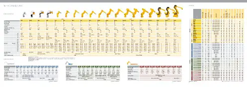
设备规格高效能和高灵活性Condor Sigma马上导入测试在过去十几年的客户经验中, XYZTEC 赛世铁克的 Condor Sigma 将推拉力测试带领到一个全新领域. 它除了使用现有最先进的科技也同时整合许多前所未有的创新设计,设立了整个产业的新标准. 它先进和宽广的规格除了确保可以执行所有产业已经在执行的测试,也同时可以针对一些特殊及有挑战性的应用提供解决方案现有其他厂牌的使用者将会发现,在 Condor Sigma 机台上,你可以非常容易将现有测试流程及方式在最短的时间转换到最新技术的Condor Sigma 平台上. 它的高效能无庸置疑是目前业界最好的推拉力测试机, 请不要跟我们说一样的话,你应该有更好的形容词,马上导入测试.强大的 SPC 软体和简单明了的图形,提供你完全掌控生产流程软体可支援定义不同层级之使用者权限. 这里所展示的是操作画面非常容易学习© XYZTEC 2012 Version 01-02-12C o n d o r S i g m a高效能和高灵活性Condor Sigma 是目前市面上最先进的推拉力测试机, 结合来自 Condor 系列独特的强处,最新的工艺和创新. 不论你是需要一台单一功能专用或多功能推拉力测试机, Condor Sigma 绝对是你最佳的选择,系统提供独一无二 0.075% 精度, 最佳人体工学设计, 最快的测试速度, 最高的灵活性,最低成本和最佳性价比使用现有的工具和夹具Sigma 机台被设计来相容大多数其它厂家现有勾针,推刀和夹具.你或许已经有库存却不用担心困扰. 我们提供相容模式来确保你的测量结果与现有其它厂家机台的一致性.搭配强大的直觉式软件,操作员可以延续他们在既有设备及流程的经验,快速学习操作 Condor Sigma .多合一旋转测量模块RMUXYZTEC 是非常着名的公司,尤其是在许多创新的推拉力测试解决方案.而多合一旋转测量模块就是 XYZTEC 公司利用客户回馈所设计的结果.现在, RMU 能力已经可以到达 200 kgf 推力和 100 kgf 的拉力和下压力.更具弹性的配置,允许你搭配 1 到 6 个传感器模块,来达成全自动化或手动测试.相对于手动更换模块, RMU 排除了暖机时间和大大减少手动更换模块所造成传感器损坏的风险.更轻更快的 landing 和 高解析度更广泛与多样化的测试都可能实现在Condor Sigma 上,量测范围可以从小于 1 gf (克)到 200 kgf (公斤). 数位化温度变异自动修正补偿以及目前全球最高的 24 bits 解析度提供了更可靠及高再现性的量测结果.可程式化设定执行推力最小的 landing force 到几克重. 甚至在高速测试中设定一个非常轻的 landing 都是有可能的.搭配了 50 mm/s 的 X, Y & Z 三轴,将可快速执行任何测试,并于开机后快速到达任何的测试位置Condor Sigma马上导入测试推拉力测试技术的世界领导品牌模块化和开放式设计所有的 sensor 传感器都可以互相被替换的,可以将其装在单一测试头内或是六合一旋转测试头. 所有 sensor 传感器都是被精准校正和测试完成, 任何一个 sensor 传感器,都可以在几分钟内被移除和更换三轴皆为高扭力设计, 且开放式的工作台面设计, 可容纳不管多寛或多小的待测物, 省却以往还需使用特殊治具的困扰.高精度的快拆式夹具和测试模块,可以确保快速更换测试样品和立即进入测试.内建拍照及自动化 CCD Camera标准配置含一部直立式自动化 CCD Camera ,距离测试点非常的近,可选择两种不同的放大倍率, 以及 1.5 μm 的光学解析度. Condor Sigma 最多可以搭配三个独立的 CCD Camera 在不同的位置,来提供撷取最佳影像的可能性.针对自动化测试, 也提供对位靶点的自动辨识.金球推力bending (下压弯曲)量规功能cavity test (包覆式)推力锡球夹拉力晶片推力疲劳测试高速冲击测试overhanging die 堆叠晶片passivation layer gold ball shear 防焊层金球推力高度探测功能铝带撕裂力铝带拉力锡球推力元件垂直拉力区域性锡球推力夹拉力非垂直性拉力wedge 和铝带推力金线拉力简单的样品取放 : 可伸缩水平移动显微镜支架人体工学设计的操作杆: 所有的操作都可在你的指尖完成快拆介面:更换夹具在数秒内。
APPLICATION: Telehandlers: MF 25T (LJ31191);Wheel Tractors: MF 60HX (LJ31231);QTY ITEM # DESCRIPTION LETTERED ITEMSINCLUDED IN KIT1 974184 In-Frame Kit I1 975184 Out-of-Frame Kit O1 976184 Major Kit M1 977184 Premium Kit (979142 Valve Train Kit Included) P4 4 4 4 4 4 171125 171227 171274 171131 171361 171468 Sleeve & Piston Asb (Piston Stamped "KS") (1) Piston Asb, Thru U424723U (Piston Stamped "KS") (1) (2)Piston Asb, After U424723U (Piston Stamped "ML") (1) (3)Liner (Finished / No Fire Dam / 4.103" OD) (4)Liner (Semi-Finished / No Fire Dam / 4.105" OD) (5)005 Liner ShimP M O I4 171272 Piston Ring Set (1-1/8K 1-3/32 1-3/16)4 4 4 4 271261 271262 271263 271264 STD Rod Bearing .010 Rod Bearing.020 Rod Bearing.030 Rod BearingP M O I1 1 1 1 271161 271162 271163 271164 STD Main Set, wo/Thrust Washers .010 Main Set, wo/Thrust Washers.020 Main Set, wo/Thrust Washers.030 Main Set, wo/Thrust WashersP M O I1 1 1 271119 271125 271126 STD Thrust Washer Set .007 Thrust Washer Set.010 Thrust Washer SetP M O I1 1 1 8 8 4 371321 371132 371117 371143 371192 371318 Head Gasket Set Head GasketValve Cover GasketValve Seal (Umbrella)Valve Seal (O-Ring)Nozzle Dust Seal Kit "Not In Sets Or Kits"P M O I1 1 1 1 1 371292 371149 371235 371167 371282 Lower Gasket Set wo/Seals Timing Cover Gasket Fuel Line Seal Kit (23 Seals & Washers) "Not In Gkt Sets" Pan Gasket Set, Cast Pan (Includes 6 Oil Flange Gaskets) Pan Gasket, Steel Pan P P M M O OII1 1 1 371146 371145 771159 Front Crank Seal (Viton Lip Type) (7) Rear Crank Seal (Viton Lip Type) (8) Rear Block Bridge PieceP P M M O O4 1 4 271135 271127 771171 Pin Bushing (1.500" Pin) Cam Bearing (Finished ID) Balancer Weight BushingsP P M M8 8 1 771151 771148 771293 Connecting Rod Bolt Connecting Rod Nut Head Bolt Kit (Ribbed Blocks / .500" CB)P P MM(1)ML&KS pistons are different weights, replace in sets, DO NOT MIX (2)Untopped KS Piston-171415 (3)Untopped ML Piston-171416APPLICATION: Telehandlers: MF 25T (LJ31191);Wheel Tractors: MF 60HX (LJ31231);QTY ITEM # DESCRIPTION LETTERED ITEMSINCLUDED IN KIT1 979521 Camshaft Kit C1 979142 Valve Train Kit V1 1 8 571134 271249 571123 Camshaft "Cam Bolt Lock Plate - 571162" Camshaft Thrust Washer (1.750 X 2.873 X .217) (10) Tappet CC4 4 471123 471135 STD Exhaust Valve (45º / Bi-Metal / Chromed Stem) STD Intake Valve (30º / Alloy / Chromed Stem) V V4 471132 Exhaust Guide V4 471131 Intake Guide V8 471134 Outer Valve Spring (8 Coils / 2.5" Free Length) V8 471133 Inner Valve Spring (9 Coils / 2.0" Free Length) V8 471229 Spring Seat (Stepped/.640" ID)8 471222 Spring Retainer16 471146 Keeper (Half) V4 471111 Exhaust Seat (1.248 x 1.681 x .374 Stepped Top)4 471224 LH Rocker Arm (Adj Screw & Lock Nut Not Included) (11)4 471225 RH Rocker Arm (Adj Screw & Lock Nut Not Included) (11)1 471227 Rocker Arm Shaft (12) "Includes 471176 Plugs"1 571171 Cam Gear (Steel / 56 Teeth)1 571113 Crank Gear (28 Teeth) 1 571163 Idler Gear (Steel / 63 Teeth) (13)1 571145 Idler Gear Hub8 571117 Push Rod1 671142 Oil Pump Kit (Gears,Shaft,Plate,Valve,Spring,Cap,Gkts)1 671143 Oil Pump Body, w/LH Oil Filter (Cast Gear Housing)1 671146 Oil Pump Inlet Strainer4 671157 Piston Cooling Jet4 671158 Piston Cooling Check Valve1 671149 Oil Cooler1 771181 Crank Kit (Spline Nose / Lip Seal)4 771194 Connecting Rod (1.500" Pin)1 771317 Cylinder Head Assembly (Includes Valves & Springs)1 771164 Balancer Assembly, Engines w/LH Oil Filter (Incls Oil Pump)1 771165 Balancer Kit (3-Shafts 2-Gears 2-Keys 4-Brgs)2 771197 Balancer Gear (3 Bolt / 1.375 ID / 30T)1 771286 Expansion Plug Kit: Thru U280718S (19 Head&Block Plugs)1 771294 Expansion Plug Kit: After U280718S (20 Head&Block Plugs)1 871138 Thermostat (2.125" / Bypass)1 871229 Water Pump wo/Pulley1 871228 Block Heater (1.250")1 871182 Manifold Heater Plug (Blade Terminal)1 871226 Fuel Pump (4 Bolt / One Port Toward Block)(10)U729165B-U732690B Uses 271239 (1.750 X 2.873 X .243 Recessed Face) (11)Adj Screw - 471226 / Lock Nut - 571139。
斯堪尼亚动力链发展史一、斯堪尼亚公司简介斯堪尼亚(Scania)是一家瑞典汽车制造商,成立于1891年。
公司主要致力于生产商用汽车,包括卡车、客车、特种车辆等。
此外,斯堪尼亚还提供一系列汽车零部件,如发动机、传动系统等。
作为全球商用车行业的领军企业,斯堪尼亚始终以高品质、高性能和环保为核心竞争力。
二、斯堪尼亚动力链发展历程1.初期发展斯堪尼亚在成立之初,便开始研发和生产自己的动力链产品。
早期,公司主要生产蒸汽动力车,随着内燃机的发明和应用,斯堪尼亚迅速转向柴油发动机的研发。
2.技术创新斯堪尼亚在柴油发动机技术上始终保持领先地位,其创新成果包括首次采用共轨燃油喷射系统、涡轮增压技术等。
这些技术的应用使斯堪尼亚动力链在性能、燃油经济性和环保方面具有显著优势。
3.市场拓展随着公司技术的不断提升,斯堪尼亚开始积极拓展国际市场。
上世纪80年代,斯堪尼亚进入中国市场,与国内企业展开合作,逐步扩大市场份额。
4.当代发展近年来,斯堪尼亚继续加大研发投入,推出一系列具有先进技术的新产品。
在满足欧盟严格的排放标准的同时,斯堪尼亚动力链在性能、燃油经济性和可靠性方面得到更多用户的认可。
三、斯堪尼亚动力链的核心技术1.柴油发动机技术斯堪尼亚在柴油发动机领域拥有世界领先的技术,其产品具有高扭矩、低油耗和低排放的特点。
通过采用共轨燃油喷射系统、废气再循环技术等,斯堪尼亚发动机在环保和燃油经济性方面表现出色。
2.传动系统技术斯堪尼亚传动系统采用模块化设计,具有较高的可靠性和适应性。
公司的自动变速器产品在商用车市场具有较高份额,其技术水平堪称业界标杆。
3.电气化技术随着电动汽车市场的快速发展,斯堪尼亚也在积极布局电气化技术。
公司已推出多款电动卡车和客车,并在充电设施、电池技术等方面取得重要突破。
四、斯堪尼亚在中国市场的发展1.进入中国市场早在上世纪80年代,斯堪尼亚便进入中国市场,与中国企业展开合作。
凭借高性能、环保的特点,斯堪尼亚产品在中国市场逐渐获得认可。
Speed-Sheet™Model 6010For technical assistance:USA: 1-800-327-0770Operations Manual2010/106010-009-001 REV D WarrantyStryker EMS warrants to the original purchaser that the Stryker Speed-Sheet should be free from manufacturing non-conformances that affect product performance and customer satisfaction for a period of one (1) year after date of delivery. Stryker’s obligation under this warranty is expressly limited to supplying replacement parts.STRYKER M AKES NO OTHER WARRANTY OR REPRESENTATION EITHER EXPRESSED OR IM PLIED, EXCEPT AS SET FORTH HEREIN. THERE IS NO WARRANTY OF MERCHANTABILITY AND THERE ARE NO WARRANTIES OF FITNESS FOR ANY PARTICULAR PURPOSE. IN NO EVENT SHALL STRYKER BE LIABLE HEREUNDER FOR INCIDENTAL OR CONSEQUENTIAL DAM AGES ARISING FROM OR IN ANY M ANNER RELATED TO SALES OR USE OF ANY SUCH EQUIPMENT.RETURN POLICYSpeed-Sheet may be returned up to 60 days of receipt under the following conditions:Prior to 30 Days • Product must be unused , undamaged , and in the original packaging.• Customer will receive a full refund.Prior to 60 Days • Product must be unused , undamaged , and in the original packaging.• Customer is responsible for a 15% restocking fee.RETURN AUTHORIZATIONStryker customer service department must approve any merchandise return and will provide an authorization number to be printed on any returned merchandise. Stryker reserves the right to charge shipping and restocking fees on returned items. SPECIAL, MODIFIED, OR DISCONTINUED ITEMS NOT SUBJECT TO RETURN.DAMAGED MERCHANDISE ICC Regulations require that claims for damaged merchandise must be made with the carrier within fifteen(15) days of receipt of merchandise. DO NOT ACCEPT DAMAGED SHIPMENTS UNLESS SUCH DAMAGE IS NOTED ON THE DELIVERY RECEIPT AT THE TIME OF RECEIPT. Upon prompt notification, Stryker will file afreight claim with the appropriate carrier for damages incurred. Claim will be limited in amount to the actualreplacement cost. In the event that this information is not received by Stryker within the fifteen (15) day periodfollowing the delivery of the merchandise, or the damage was not noted on the delivery receipt at the time of receipt, the customer will be responsible for payment of the original invoice in full. Claims for any shortshipment must be made within thirty (30) days of invoice.INTERNATIONAL WARRANTY CLAUSE This warranty reflects U.S. domestic policy. Warranty outside the U.S. may vary by country. Please contact yourlocal Stryker Medical representative for additional information.PATENT INFORMATION Stryker Speed-Sheet is covered by one or more of the following patents:United States7,650,654The yellow and black color scheme is a proprietary trademark of Stryker Corporation.2010/106010-009-001 REV D CLEANING SPEED-SHEET (IF NOT ACTIVATED)If Speed-Sheet was not activated for a patient transfer, it can be manually cleaned (upto 10 times) and placed back on the cot mattress for the next response. To clean, apply one of the suggested cleaners by spray or pre-soaked wipes and allow the cleaner to dry. Inspect the cleaned Speed-Sheet for obvious damage (tears, abrasions, or punctures) before placing it back on the cot mattress to make sure that it was not activated or damaged.Suggested cleaners for Speed-Sheet include:• Quaternary Cleaners (active ingredient - ammonium chloride)• Phenolic Cleaners (active ingredient - o-phenylphenol)• Chlorinated Bleach Solution (5.25% - less than 1 part bleach to 100 parts water)Note: Use these cleaners in the concentrations recommended by their manufacturer.Do not use Virex® TB germicidal or alcohol-based products on Speed-Sheet.CleaningWARNING •Do not place Speed-Sheet under patients that are not being transported.• Remove Speed-Sheet from under the patient if it is activated before the cot reaches the receiving surface.• Do not use Speed-Sheet to transfer patients with suspected spinal injuries.• Do not attempt to transfer patient loads greater than what the operators can safely manage. Evaluate the load and use additional assistance if necessary.• Do not reuse an activated Speed-Sheet; it is not stable for patient transport.•Inspect Speed-Sheet for obvious damage (tears, abrasions, or punctures) before placing it back on the cot mattress to make sure that it was not activated ordamaged.• Do not use a Speed-Sheet if any obvious damage is observed upon inspection.•Failure to properly clean or dispose of a contaminated Speed-Sheet increases therisk of exposure to bloodborne pathogens.Note: Speed-Sheet is made with latex-free materials.Safety PrecautionsEuropean Representative Stryker FranceZAC Satolas Green Pusignan Av. De Satolas Green 69881 MEYZIEU CedexFranceManufactured For Stryker Medical 3800 E. Centre Ave.Portage, MI 49002U.S.A.Operation GuideALTERNATIVE USE: TRANSFERRING PATIENT ONTO COT1. Remove one Speed-Sheet from the dispenser.2. Verify that the Speed-Sheet has not reached its expiration date.3. Unfold Speed-Sheet.4. Gently tilt the patient onto their side.5. Center Speed-Sheet under the patient and put a linen sheet on top of Speed-Sheet.6. Lower the patient onto the linen sheet.7.See Transferring Patient Off the Cot instructions to transfer the patient onto the cot.Note: A separate Speed-Sheet may be prepared on the cot mattress for later use when transferring the patient off the cot. That Speed-Sheet should be tucked underneath the Speed-Sheet that was placed under the patient.Operation GuideTRANSFERRING PATIENT OFF THE COT1. Position the cot alongside the receiving patient support platform.2. Adjust the cot height so the cot mattress is flat and approximately 1 in (2.5 cm)above the receiving patient support surface.3. Secure the cot and patient support platform together to prevent separation.4. Lower all siderails.5. Tear at least one red tab 3-6 in (8-16 cm) to activate Speed-Sheet (Figure 3 orFigure 4). Note: Tearing more than one tab can improve performance.6. With at least one operator on each side of the patient, pull on the linen sheet totransfer the patient (Figure 5).Note: Pull on the linen sheet. Do NOT pull on Speed-Sheet.Pull horizontally. Do NOT lift the linen sheet.An overhand grip on the linen sheet encourages proper pulling technique.If the patient’s condition permits, the operator on the cot side of the transfer may gently push on the patient rather than grasping the linen sheet.7. Raise the siderails on both sides of the patient after the transfer.8. Dispose of the activated Speed-Sheet according to local medical disposal protocoland replace it with a new one before the next response.Operation Guide PREPARING THE COT BEFORE A RESPONSE 1. Remove one Speed-Sheet from the dispenser.2. Verify that the Speed-Sheet has not reached its expiration date (Figure 1).3. Unfold and center Speed-Sheet directly on top of the cot mattress.4. Inspect Speed-Sheet for obvious damage (tears, abrasions, or punctures).5. Place a linen sheet on top of Speed-Sheet (Figure 2).This manual is designed to assist you with the operation of the Stryker Speed-Sheet™. Read this manual thoroughly before using the equipment and keep a copy on file. Toensure safe operation, establish procedures for training all staff according to the usage described in this manual.INTENDED USE OF PRODUCTThe model 6010 Speed-Sheet is intended to be used by trained personnel as a manual lateral patient transfer aid. The device is primarily intended to assist in the transfer of a body in a supine position from an ambulance cot or mortuary cot to an adjacent surface. Alternatively, the device may be used to transfer a body from an adjacent surface onto an ambulance cot or mortuary cot.PRODUCT DESCRIPTIONSpeed-Sheet is a disposable device that significantly reduces the force required to transfer a patient from one surface to another. Speed-Sheet is stable before activation, so it can be placed on the cot mattress before a response and remain under the patient while they are transported. When transferring the patient to another support surface, Speed-Sheet can then be activated to minimize the friction between the linen sheet and cot mattress. Speed-Sheet also provides a fluid-impermeable barrier between the patient and cot mattress for faster clean up.SPECIFICATIONS10-Pack Part Number 6010-001-010Maximum Patient Weight 700 lb 318 kg Speed-Sheet Dimensions 72 in x 23.5 in183 cm x 60 cm Dispenser Dimensions 12.75 in x 8.75 in x 4.75 in 32 cm x 22 cm x 12 cm Dispenser Weight(includes 10 Speed-Sheets) 4.5 lb 2 kg Storage Temperature -4°F - 104°F-20°C - 40°CStorage Relative Humidity0% - 100%IntroductionFigure 2Figure 3Figure 4Figure 5WARNING/NOTE DEFINITIONThe words WARNING and NOTE carry special meanings and should be carefully reviewed.WARNINGAlerts the reader about a situation which, if not avoided, could result in death or serious injury. It may also describe potential serious adverse reactions and safety hazards.Note: Provides special information to make maintenance easier or important instructions clearer.Figure 1。