AUTO DESK INVENTOR 2008机械设计实战教程09 表达视图相关技术(陈伯雄)
- 格式:pdf
- 大小:1.09 MB
- 文档页数:9
第9章 零件库技术1. Inventor 标准件库的使用Inventor R6之后的库,是随着安装过程自行装入的,这是Autodesk 提供的各种国标准的标准件库,也包括了一部分GB 标准件。
库中定义的各种标准件可以直接加入到Inventor 的装配之中。
需要在装配环境中使用。
(本章中与InventorR8相同的操作,将沿用老的AVI 文件)(1) 界面和操作规则在前边讨论型材库的使用中,已经介绍了一些相关的规则。
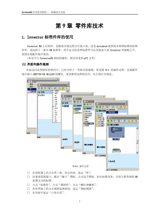
参见图9-1的操作过程,在装配环境中插入GB5780-86 M12x50的螺钉,笔者推荐这样的次序,从左到右分别是:□ 在浏览器上沿点击黑三角,拉出列表,选定“库”;□ 拉宽浏览器窗口,露出“漏斗”图标,点击这个图标,拉出标准列表。
关闭与要查找的GB标准无关的标准;□ 点击“标准件”;点击“紧固件”;点击“螺钉和螺栓”;□ 在库界面上沿点击视图选择按钮,选定“图标视图”;□ 在列表中选定“六角头型”。
图9-1 操作过程结果将出现图9-2左边的结果界面,选定“GB5780-86…”项目,再接着弹出的图9-2右边的界面中展开参数列表,选定需要的参数…最后,将光标放在标准件模型显示窗口,光标形状将改成“笔”的样子,拖动这支笔到图形区,松开鼠标按钮,将创建这个标准件模型。
点击一次鼠标,则放置一个零件… 直到在右键菜单中“结束”。
(2) 关于GB 标准件这是我国用户必然关心的问题。
注意:目前的检索规则仍然不符合GB 分类标准,按工程师的习惯规则,可能找不到东西。
按GB 标准(参见图9-3左),“盘头型”有,但只有一种,就是GB/T3632-1995钢结构用扭剪型高强度螺栓。
但Inventor 的作者,却在其中包含了许多其它的类型(参见图9-7右),例如将“半圆头”的GB/T12-1988半圆头方颈螺栓放在“盘头型”的类别之中了…这种分类实例还有一些,例如将四方头螺钉(GB8-88)放在了“六角头”类型里边…总之,Inventor 不是完全按工程师的现有习惯分类,这样,找不到相关的零件,就是时常会碰到的事情。

AutodeskInventor机械设计软件使用教程Chapter 1: Introduction to Autodesk Inventor Mechanical Design Software (200 words)Autodesk Inventor is a powerful and widely-used software tool for mechanical design. Designed by Autodesk, this software provides engineers and designers with a comprehensive set of tools for creating, rendering, and simulating 3D models. With its intuitive interface and extensive features, Inventor is a popular choice for professionals in various industries, including manufacturing, automotive, and aerospace.In this tutorial, we will explore the key features and functionalities of Autodesk Inventor. This guide is designed for beginners and will provide step-by-step instructions on how to use the software effectively.Chapter 2: Getting Started with Autodesk Inventor (300 words)Before diving into the intricacies of Autodesk Inventor, it's important to familiarize yourself with the basic layout and tools. Upon launching the software, you will be greeted with an interface consisting of various panels, menus, and a workspace.This chapter will guide you through the process of creating a new project and setting up your workspace. You will also learn how to navigate the interface and customize the layout to suit your preferences. Additionally, you will be introduced to the different file types supported by Inventor and how to save your work.Chapter 3: Creating 3D Models (400 words)One of the core functionalities of Autodesk Inventor is the ability to create 3D models of mechanical components. In this chapter, we will delve into the different techniques and tools available for creating these models.You will learn how to sketch 2D profiles and use the extrude, revolve, and sweep commands to convert these profiles into 3D objects. We will also explore the wide range of construction tools, including fillets, chamfers, and patterns, that allow you to add intricate details to your models.Chapter 4: Assembly and Constraints (300 words)In a real-world mechanical design project, multiple components come together to form an assembly. Autodesk Inventor provides a robust set of tools for creating and managing these assemblies.This chapter will guide you through the assembly process, from inserting components to defining relationships between them using constraints. You will also learn how to manipulate assemblies, hide and show components, and create exploded views for documentation purposes.Chapter 5: Simulating and Analyzing Models (300 words)Autodesk Inventor offers powerful simulation and analysis tools that allow you to test the performance and behavior of your designs before manufacturing or production.In this chapter, you will learn how to apply loads, define material properties, and run simulation studies to determine factors such as stress, displacement, and interference. Additionally, you will explore the motion analysis tools available in Inventor, which enable you to simulate the movement of assembly components.Chapter 6: Documentation and Presentation (300 words)Effective communication of your design ideas is crucial in the engineering field. Autodesk Inventor provides a set of tools for creating technical drawings, dimensioning, and generating documentation.This chapter will cover the creation of 2D drawings, including the placement of views, adding dimensions and annotations, and creating a bill of materials. You will also learn how to render 3D models for realistic visualizations and create interactive presentations.Conclusion: Mastering Autodesk Inventor (200 words)In conclusion, Autodesk Inventor is a powerful software tool that is widely used in the mechanical design industry. With its comprehensive set of features, intuitive interface, and simulation capabilities, it provides engineers and designers with the tools they need to bring their concepts to life.In this tutorial, we have explored the key features of Autodesk Inventor, including creating 3D models, managing assemblies, simulating designs, and creating technical documentation. By following the step-by-step instructions provided, you will be well on your way to mastering this software and becoming proficient in mechanical design. Remember to practice regularly and experiment with different design scenarios to enhance your skills.。

第9章 表达视图相关技术传统设计中,机器装配过程是比较难以表达的。
Inventor 的“表达视图”正是解决这种装配过程表达的有效工具。
表达视图可以输出成*.AVI/*.WMV 等动画文件,可在Windows 通用的播放工具中打开和播放,也可以借此创建工程图。
实际上“表达视图”的精确名称应当是“装配分解模型”。
这里创建的直接结果并非通常意义上的“视图”,而是一个对现有三维装配模型进行特殊位置和查看规则定义的模型;这个模型中不具有编辑原始零部件的能力。
Inventor 关于表达视图的功能,已经在Help 中有了详尽的解释。
这个功能中,我们主要是按照Inventor 的规则做。
1 创建表达视图的一般操作过程在菜单中“文件(F)”->“新建(N)…”,选定IPN 扩展名的模版;在“表达视图”工具面板上启用“创建视图”工具;选定依照的装配文件(例如:09-01.IAM);参见图9-1。
在接着弹出的“选择部件”界面中选定依照的设计视图(按下“选项”按钮并参见图9-1右)和分解方式(图9-1中),之后“确定”。
在实际应用中,极少使用“自动”分解方式。
图9-1 表达视图创建2 设置零件的装配分解创建了表达视图之后,浏览器中的内容参见图9-2。
以下的操作将从浏览器中选定一个或几个零部件开始。
2.1 定义单个零件的移动这是装配分解中最基础的动作之一,这是将选定的零部件从装配的最终位置拉出来,以直线移动的方式放到分解之后的位置上。
选定轴零件,在右键菜单中“调整零部件位置(K)…”,接着将弹出“调整零部件位置”的对话框。
首先的操作就是确定坐标系。
要将光标放在这个零件与移动方向正交或平行的典型结构的表面上(例如端面),Inventor 将会感应到相关特征的数据,将图9-2 典型界面表现坐标系安放到合适的位置上。
参见图9-3。
按照Inventor的规则,选定不同的几何结构,会将坐标系按对应的规则安放:图9-3 确定移动坐标系直线:将Z 轴与直线重合圆弧或圆:将Z 轴放置在圆或者弧的轴线上平面:将XY 面放在这个平面上 圆柱、圆锥面:将Z 轴放在圆面(也可以是不完整的圆面)的轴线上之后在“平移”栏目中选定“移动”(栏目名应当是“动作”,包括移动和旋转,不仅仅是“平移”),设置轴Z 的反方向移动100mm,并按下“应用”(绿对号)按钮,参见图9-4。
最新AutoCAD2008培训教程在当今的设计领域,AutoCAD 无疑是一款至关重要的工具。
而AutoCAD2008 作为其中的一个经典版本,仍然被广泛应用于许多行业。
无论您是初学者,还是希望进一步提升技能的进阶用户,本教程都将为您提供全面且实用的指导。
一、AutoCAD2008 简介AutoCAD2008 是由Autodesk 公司开发的一款计算机辅助设计软件,它具有强大的绘图和编辑功能,可以用于建筑设计、机械设计、电气设计等众多领域。
与之前的版本相比,AutoCAD2008 在性能、稳定性和用户体验方面都有了显著的提升。
二、安装与启动首先,我们来了解一下 AutoCAD2008 的安装过程。
您需要准备好安装光盘或从官方网站下载安装文件。
在安装过程中,按照提示逐步操作,选择合适的安装路径和组件。
安装完成后,在桌面上会出现 AutoCAD2008 的快捷方式图标。
双击该图标即可启动软件。
启动后,您将看到一个简洁的用户界面,包括菜单栏、工具栏、绘图区等。
三、用户界面与基本操作AutoCAD2008 的用户界面主要由菜单栏、工具栏、绘图区、命令行和状态栏组成。
菜单栏包含了各种命令和选项,您可以通过点击菜单来执行相应的操作。
工具栏提供了常用命令的快捷按钮,方便您快速访问。
绘图区是您进行绘图和编辑的主要区域。
在绘图区中,您可以使用鼠标滚轮进行缩放和平移操作,以便更好地查看和编辑图形。
命令行用于输入命令和显示提示信息。
您可以直接在命令行中输入命令,然后按回车键执行。
状态栏显示了当前的绘图状态,如坐标、捕捉模式等。
四、绘图命令接下来,让我们学习一些基本的绘图命令。
1、直线(LINE)命令输入“LINE”或点击工具栏中的直线按钮。
在绘图区指定起点和终点,即可绘制一条直线。
2、圆(CIRCLE)命令输入“CIRCLE”或点击工具栏中的圆按钮。
可以选择通过指定圆心和半径、直径、三点等方式来绘制圆。
3、矩形(RECTANG)命令输入“RECTANG”或点击工具栏中的矩形按钮。